


H1000
compass installation
IS- 2506

Brookes & Gatehouse Ltd
Premier Way,
Abbey Park,
Romsey,
SO51 9AQ
UK
Tel: (+44) (0)1794 518448
Fax: (+44) (0)1794 518077
Global Website: www.BandG.com
© 2001 Brookes & Gatehouse Ltd
B&G USA
13191 56th Court,
Suite 106,
Clearwater,
Florida 33760
USA
Tel: (+1) 727 540 0229
Fax: (+1) 727 540 0281
B&G France
Place Bernard Moitessier,
Plateau Nautique,
17000 La Rochelle,
France
Tel: (+33) 5 46 44 01 01
Fax: (+33) 5 46 34 30 07

CE Certification:
This equipment generates, uses, and can radiate radio frequency energy and, if not installed and used in
accordance with the instruction s, may cause harmful interference to radio communications. However, th ere is no
guarantee that interference will not occur in a particular in stallation. If this equipment does cause harmfu l
interference, the user is encouraged to try to correct th e in terferen ce by relocating the equipment or connecting
the equipment to a different circuit. Consult an authorised dealer or other qu alified technician for additional help
if these remedies do not correct the problem.
This device meets requirements for CFR47 Part 15 of the FCC limits for Class B equipment.
The
h1000
navigation and radiocommunication equipment and systems .
:
: :
meets the standards set out in European Standard EN 60945: 1997 IEC 945 : 1996 for maritime
CE-Zertifizierung::::
Dieses Gerät erzeugt und verwendet HF-Energie und kann diese ausstrahlen; wenn es nicht gemäß der
Anweisungen installiert und verwendet wird, kann es störende Interferenzen mit dem Funkverkehr verursachen.
Allerdings wird nicht gewährleistet, dass es bei eine r bestimmten Installation keine Interferenzen geben wird.
Wenn dieses Gerät Störungen verursacht, sollte der Benutzer versuchen, die Störungen zu beheben, indem er das
Gerät anders aufstellt oder an einen anderen Stromkreis anschließt. Wenden Sie sich für zu sätzliche Hilfe an den
Vertragshändler oder einen Fachmann, wenn das Problem durch diese Maßnahmen nicht behoben werden kann.
Dieses Gerät entspricht den Anforderungen für CFR47 Teil 15 der FCC-Begrenzungen für Geräte der Klasse B.
Der
h1000
und Funkkommunikationsgeräte und -systeme.
erfüllt die Vorschriften der Europäischen Norm EN 60945:1997 IEC 945:1996 für maritime Navigations-
Certificación CE:
Este equipo genera, utiliza y puede radiar energía de radiofrecuencias y si no se instala y utiliza de acuerdo con
las instrucciones, puede causar interferencias dañinas con las comunicaciones de radio. Sin embargo, no hay
ninguna garantía de que no ocurran interferencias en una instalación particular. Si este equipo causa
interferencias, se aconseja al usuario que in ten te elim in arlas cambiando de sitio el equipo o conectándolo a un
circuito diferente. Si estas acciones no corrigen el problema, consulte a un concesionario autorizado u otro
técnico calificado para que le ayude.
Este dispositivo cumple con los requ isitos de CFR47 Parte 15 de los límites F CC para equ ipo de Clase B.
El
h1000
satisface las normas establecidas en la Norma Europea EN 60945: 1997 IEC 945 : 1996 para equipo y
sistemas de navegación y radio comun icaciones marítimas.

Certification CE :
Cet équipement émet et utilise une fréquence qui peut rayonner de l’énergie et, si son installation et son
utilisation ne sont pas conformes aux instructions, il peut être la cause de parasites nuisibles aux
communications radio. Il n’y a cependant aucune garantie que des parasites ne se produiront pas dans une
installation spécifique. Si cet équipement est la cause de parasites nuisibles, il est conseillé à l’utilisateu r de
remédier à ces parasites en déplaçant les appareils ou en effectuant le branchement su r un circuit différent. Il
faudra consulter un agent agréé ou un autre technicien qualifié pour une aide supplémentaire si le problème
n’est pas résolu par ces interventions..
Cet appareil est conforme aux normes requises pour la certification CF R47 Part 15 des limites FCC aux USA pour
les équipements de Classe B.
Le
h1000
est conforme aux normes définies par la Norme Européenne EN 60945: 1997 IEC 945 : 1996 pour la
navigation maritime et les équipements et systèmes de télécommunications .
Marcatura CE::::
Questo equipaggiamento genera, utilizza e può irradiare l’energia della frequenza radio e, se non viene installato
e usato in base alle istruzioni, può causare interferenze pericolose alle comunicazioni radio. Non vi è neppure
nessuna garanzia che una determinata installazione non sia soggetta a interferenze. Se questo apparecchio
causa interferenze nocive, incoraggiamo l’utente a cercare di correggere tali interferenze riposizionan d o o
collegando l’equipaggiamento a un circuito diverso. Rivolgersi a un concessionario autorizzato o a un tecnico
opportunamente addestrato per ulteriore assistenza se questi rimedi non correggono da soli il problema.
Questo dispositivo soddisfa i requisiti della normativa CFR47 Parte 15 dei Limiti FCC per l’equipaggiam en to
Classe B.
Il modello
equipaggiamento e sistemi per la navigazione marittima e le radiocomu n icazioni.
h1000
soddisfa gli standard esposti nella normativa europea EN 60945: 1997 IEC 945: 1996 per

trademark
All rights reserved. No part of this manual may be reproduced or transmitted in any form or by any means including
photocopying and recording, without the express written permission of B&G.
Information in this document is subject to change without notice. B&G reserves the right to change or improve its
products and to make changes in the content w ith ou t obligation to notify any person or organisation of such changes.
technical specifica t ions
Dimensions mm: 110mm x 95mm x 75mm
Power Supply: 12V dc nominal (10 to 16V) via FastNet2
Power Consumption: 0.1W nominal
Operating Temp erature range: -10 to +55ºC (+14 to +130ºF)
Storage Temper a ture range: -25 to +70ºC (+13 to +158ºF)
Humidity: Up to 95% RH
Sealing: IP66 (with dust caps fitted)
Accessories: Bracket
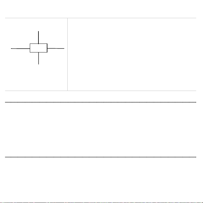
system connections
Bus cable
Bus cable
12V power cable
“HUB”
Bus cable
connections
System components share data together via a common Fastnet2 databus and
are supplied with bayonet connectors for ease of in stallation. A selection of
cable lengths are available with options for straight and right an gle
connectors to suit most requirements.
To prevent the occurrence of voltage drops on larger systems, the power
supply to the system should either be placed mid-way or at both ends of the
Fastnet2 databus. To connect power to the mid-point of the system, it is
recommended that the 4-Way Hub be used. The 4-Way Hub offers two
advantages. The first advantage is that it offers a convenient entry point for
power onto the system. The second advantage is that it conveniently allows
the system to be branched to reduce the overall length of the system. The
correct selection of Fastnet2 cable will negate the need for any plugs to be
removed from the system and ensure years of faultless operation.
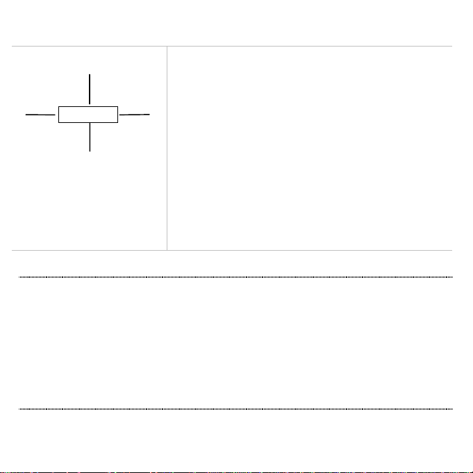
installation
installation
Mount the
• A safe distance from external magnetic interference: 3m/10ft from VHF, RDF, loudspeakers, depth sounders,
• 3m/10ft from Radar and SSB equipment.
• Externally mounted on steel vessels.
• Well protected from physical damage.
• Protected from water ingress (particularly bilge water).
• Optimum positioning: As low as pos sible to minimise effect of pitching and rolling of boat.
h1000
Compass upright on a flat vertical bulkhead where it will be:
engines, or power cables carrying heavy current.
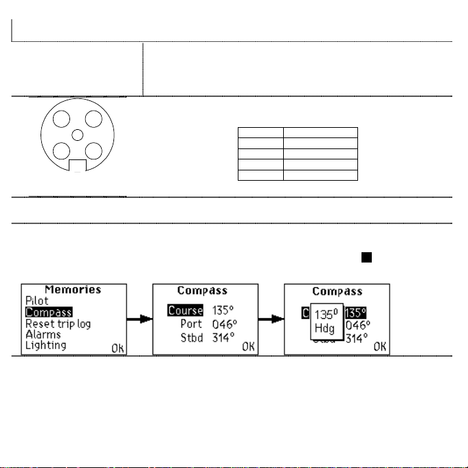
electrical connections
2 3
5
41
Front view of
male connector pins
external connections
Two FastNet² connectors are provided at the base of the unit. These connectors
allow connection to the rest of the system for th e supply of power and data.
The table below shows pin functions.
Pin Number Signal
1 12V
2 Busy
3 FastNet²4 FastNet²+
5 0V
compass memories
compass
The compass memory holds the current course and can also be user defined. Port and Starboard courses are
retained and are updated at each ENTER
returns to the Main Menu
Main Menu.
Main MenuMain Menu
ENTER key press whilst in the Tactical compass
ENTERENTER
Tactical compass page. When OK is selected control
Tactical compassTactical compass
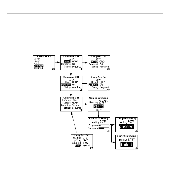
compass calibrat ion
compass calibration
Compass calibration sets sensor offset, damping, and allows a compass swin g to correct for magnetic deviation.
If the compass has not been swung the compass cal menu will show swing required. When this item is selected the
display will switch to the start menu, and show the current heading. When selecting start
current heading, a progress bar indicating how far aroun d th e complete turn the boat currently is, and an indication of
whether or not the turn rate is too fast.
When the turn is complete the compass calculates its deviation correction and the display shows passed or failed.
After a successful swing the compass cal menu will show swing passed in place of swing required.
At any point during the swing the user can select abort to end the swing and return control to the compass cal menu.
Note:
passed
is
shown under the
Swing title when a
successful compass
swing has been stored
start the display shows the
startstart
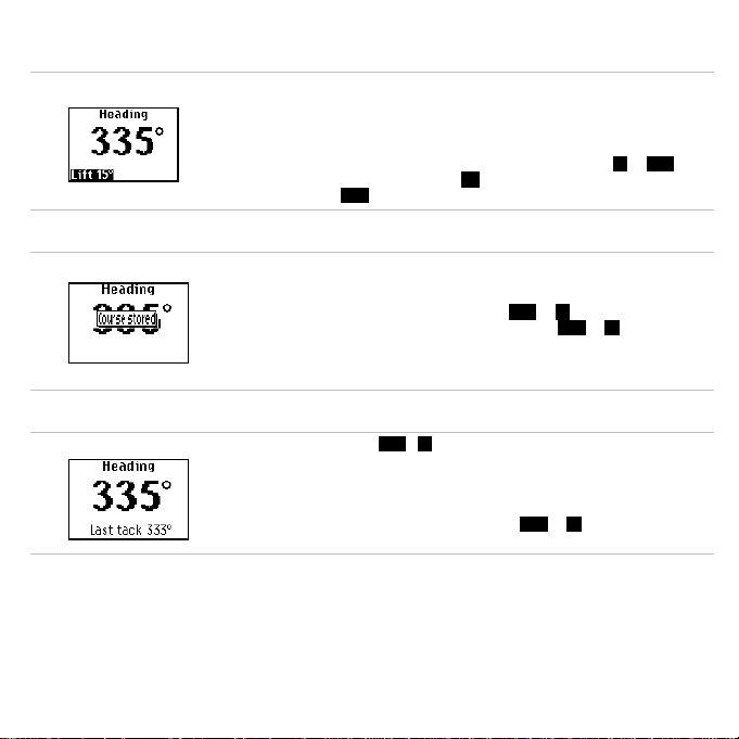
tactical compass function
storing a course
last tack information
When a compass and a wind sensor are connected to the system, the Tactical
Compass function becomes available as a full page display option.
After a tack or gybe, and the yacht is sailing a steady course, press the ENTER
key to store the displayed heading. Note, to access the Main Menu from the
Tactical Compass page, press and hold the ENTER key for two seconds.
Any deviation from the stored course is shown on the screen as a lift or head with
the corresponding number of degrees. Lift is always shown on the windward side
of the display and head on the leeward.
When the ENTER key is pressed whilst the Tactical Compass page is displayed,
the present heading is automatically stored and the head / lift trend function
reset. When this is done, the display overlays the Heading with Course stored for
two seconds, as shown in the diagram, and the head or lift legends disappear.
As soon as heading deviates from the new stored value, head or lift will b e
displayed with the number of degrees as appropriate. Resetting th e stored
course also updates the Course memory found under the Memories → Compass
menu.
When a tack occurs, the head / lift field in the bottom left or right of the display is
replaced with the last heading for that tack, providing it was previously stored by
pressing the ENTER key.
Last tack heading remains on screen until the ENTER key is pressed. When
ENTER is pressed, Last Tack information disappears, Course Stored is then
shown for two seconds, and then the appropriate head or lift information is
shown.

compass unit
deutsch

warenzeichen
Alle Rechte vorbehalten. Ohne die ausdrückliche schriftliche Genehmigung durch B&G dürfen diese Anleitung oder
Teile daraus nicht in irgendeiner Form oder mit irgendwelchen Mitteln einschließlich Fotokopie und Aufzeichnung
reproduziert oder übertragen werden.
Änderungen der Informationen in diesem Dokument ohne vorherige Bekanntmachung bleiben vorbehalten. B&G
behält sich das Recht vor, seine Produkte zu verändern oder zu verbessern und Änderungen im Inhalt vorzunehmen
ohne Verpflichtung, irgendwelche Personen oder Organisationen darüber zu informieren.
technische daten
Abmessungen: 110 mm x 95 mm x 75 mm
Spannungsversorgung: 12 V Gleichstrom nominal (10 bis 16 V) über FastNet2
Leistungsaufnahme: 0,1 W nominal
Betriebstemperaturbereich: -10 bis +55 ºC
Lagertemperaturbereich: -25 bis +70 ºC
Rel. Luftfeuchtigkeit: bis zu 95 %
Abdichtung: IP66 (Staubkappen angebracht)
Zubehör: Halterung
systemverbindungen
Bus-kabel
Bus-kabel
“Verteiler”
12V-Spannungskabel
Bus-kabel
verbindungen
Systemgeräte nutzen Daten gemeinsam über einen gemeinsamen
Fastnet2 Datenbus und verfügen über Bajonett-Steckverbinder für
einfache Installation. Verschiedene Kabellängen stehen zur Auswahl mit
geraden und Winkel-Steckverbindern zur Anpassung an die meisten
Erfordernisse.
Zur Vermeidung von Spannungsabfällen in größeren Systemen sollte die
Spannungsversorgung des Systems in der Mitte oder an beiden Enden
des Fastnet2 Datenbusses angeordnet werden. Um die Spannung in der
Mitte des Systems zuzuführen, wird der 4-Wege-Verteiler empfohlen, der
zwei Vorteile bietet. Der erste Vorteil ist der praktische Eintrittspunkt für
die Spannungsversorgung in das System. Der zweite Vorteil besteht darin,
dass das System auf einfache Weise verzweigt werden kann, um seine
Gesamtlänge zu reduzieren. Durch die richtige Wahl des Fastnet2 Kabels
wird vermieden, dass Steckverbinder aus dem System entfernt werden
müssen, sodass störungsfreier Betrieb über viele Jahre erwartet werden
kann.
Installation
installation
Den Kompass
• Sicherer Abstand von externen magnetischen Störungen: 3 m von UKW, Funkpeiler, Lautsprechern,
• 3 m von Radar und Einseitenband-Anlagen
• Externe Montage auf Stahlbooten
• Guter Schutz vor Beschädigungen
• Schutz vor Eindringen von Wasser (insbesondere Bilgenwasser)
• Optimale Lage: so tief wie möglich, um die Auswirkungen von Stampf- und Rollbewegungen des Boots
h1000
aufrecht an einem ebenen, senkrechten Schott anbringen, wo folgendes gegeben ist:
Echolot, Motoren und Starkstromkabeln
minimal zu halten
 Loading...