


Zeus 12
Zeus Multi-function Display
Installer Manual
English

Preface 1.
Disclaimer
As Navico is continuously improving this product, we retain the right to make changes to
the product at any time which may not be reflected in this version of the manual. Please
contact your nearest distributor if you require any further assistance.
It is the owner’s sole responsibility to install and use the instrument and transducers in
a manner that will not cause accidents, personal injury or property damage. The user of
this product is solely responsible for observing safe boating practices.
NAVICO HOLDING AS, AND ITS SUBSIDIARIES, BRANCHES AND AFFILIATES DISCLAIM
ALL LIABILITY FOR ANY USE OF THIS PRODUCT IN A WAY THAT MAY CAUSE ACCIDENTS,
DAMAGE OR THAT MAY VIOLATE THE LAW.
Governing Language: This statement, any instruction manuals, user guides and other
information relating to the product (Documentation) may be translated to, or has been
translated from, another language (Translation). In the event of any conflict between any
Translation of the Documentation, the English language version of the Documentation
will be the official version of the Documentation.
This manual represents the product as at the time of printing. Navico Holding AS and its
subsidiaries, branches and affiliates reserve the right to make changes to specifications
without notice.
Copyright
Copyright © 2010 Navico Holding AS.
Feedback from you
Your feedback is important and helps Navico ensure that this manual is a valuable
resource for all marine technicians. E-mail your comments or suggestions about this
manual to the following address: tech.writing@navico.com
Warranty
The warranty card is supplied as a separate document.
It is shipped with the product registration card.
In case of any queries, refer to the brand web site of your display or system.
www.bandg.com
Preface | 1

Declaration of Conformity
Hereby, Navico Holding AS declares that this Z8, Z12 is in
GB
FI
NL
FR
SE
DK
compliance with the essential requirements and other relevant
provisions of Directive 1999/5/EC.
Navico Holding AS vakuuttaa täten että Z8, Z12 tyyppinen laite
on direktiivin 1999/5/EY oleellisten vaatimusten ja sitä koskevien
direktiivin muiden ehtojen mukainen.
Hierbij verklaart Navico Holding AS dat het toestel Z8, Z12 in
overeenstemming is met de essentiële eisen en de andere relevante
bepalingen van richtlijn 1999/5/EG.
Par la présente, Navico Holding AS déclare que ce Z8, Z12 est
conforme aux exigences essentielles et aux autres dispositions de la
directive 1999/5/CE qui lui sont applicables.
Härmed intygar Navico Holding AS att denna Z8, Z12 står i
överensstämmelse med de väsentliga egenskapskrav och övriga
relevanta bestämmelser som framgår av direktiv 1999/5/EG.
Undertegnede Navico Holding AS erklærer herved, at følgende
udstyr Z8, Z12 overholder de væsentlige krav og øvrige relevante
krav i direktiv 1999/5/ EF.
Hiermit erklärt Navico Holding AS, dass sich dieses Z8, Z12 in
DE
GR
IT
ES
PT
The equipment named in this declaration, is intended for use in international waters
as well as coastal sea areas administered by countries of the E.U. and E.E.A. A full
Declaration can be obtained from www.bandg.com
Übereinstimmung mit den grundlegenden Anforderungen und den
anderen relevanten Vorschriften der Richtlinie 1999/5/EG befi ndet.
(BMWi)
Με την παρουσα Navico Holding AS δηλωνει οτι Z8, Z12
συμμορφωνεται προς τις ουσιωδεις απαιτησεις και τις λοιπες σχετικες
διαταξεις της οδηγιας 1999/5/ΕΚ.
Con la presente Navico Holding AS dichiara che questo Z8, Z12 è
conforme ai requisiti essenziali ed alle altre disposizioni pertinenti
stabilite dalla direttiva 1999/5/CE.
Por medio de la presente Navico Holding AS declara que el Z8,
Z12cumple con los requisitos esenciales y cualesquiera otras
disposiciones aplicables o exigibles de la Directiva 1999/5/CE.
Navico Holding AS declara que este Z8, Z12está conforme com os
requisitos essenciais e outras provisões da Directiva 1999/5/CE.
2 | Preface
Disposal
Waste Electrical and Electronic Equipment (WEEE)
The use of the WEEE Symbol indicates that this product may not be treated as household
waste. By ensuring this product is disposed of correctly, you will help protect the
environment.
For more detailed information about the recycling of this product, please contact your
local authority, your household waste disposal service provider or the shop where you
purchased the product.

Contents 2.
Preface ............................................................................................... 1
Introduction ....................................................................................... 6
About this Manual ............................................................................6
Conventions ................................................................................... 6
Important Safety and Warning Information ......................................... 6
Check the Parts .............................................................................. 7
Overview ............................................................................................ 8
Installing the Display .......................................................................... 10
Mounting location .......................................................................... 10
Panel Mount ................................................................................. 11
Bracket Mount .............................................................................. 12
System Architecture ........................................................................... 14
Networking, Data Interfacing .......................................................... 14
SimNet / NMEA 2000 14
Ethernet: (NETWORK ports) 14
NMEA0183 14
B&G H-Link 14
Data Bridging ............................................................................... 15
Wiring Information ............................................................................. 16
Typical System .............................................................................. 16
Standard Connections .................................................................... 17
NMEA0183 Devices 17
H3000 17
Deckman Navigation Software 17
WTP3 18
Wiring the Zeus Display ...................................................................... 19
Power .......................................................................................... 20
Connecting Power 20
Power Control 20
External Alarm .............................................................................. 23
H-Link ......................................................................................... 24
B&G H-Link LT 24
B&G H-Link Pro 24
SimNet ........................................................................................ 25
Planning and Installing a SimNet Backbone 26
Power the SimNet Network 26
Preface | 3

Ethernet ...................................................................................... 28
Dual and Multi Station 29
NMEA0183 Wiring .......................................................................... 30
Video In ....................................................................................... 31
Video Out ..................................................................................... 32
Connecting BroadBand™ Radar ....................................................... 33
Connecting HD Radar ..................................................................... 34
Connecting BSM1 Broadband Echosounder ....................................... 35
Commission the System...................................................................... 36
Turning on the system for the fi rst time ........................................... 36
Operating the Menu System ............................................................ 36
Commissioning Checklist ................................................................ 37
System settings menu 38
Language 38
Time: Local Time, Time format, Date Format 38
Power Control 38
Echosounder Setup ........................................................................ 39
Radar setup .................................................................................. 40
Data Setup ................................................................................... 42
SimNet / NMEA2000 setup 42
Source Selection (Auto select) 42
Source Selection (Manual) 42
Damping 45
Device List 45
Serial Port Setup ........................................................................... 46
NMEA 0183 Output 46
Fuel ............................................................................................. 47
Vessel Setup 47
AIS Own Vessel ............................................................................. 47
Diagnostics ................................................................................... 48
NMEA2000 Diagnostics 48
User Database UDB 48
Check GPS Signal .......................................................................... 49
4 | Preface
System Backup ............................................................................. 49
Creating a System Backup File 49
Restore a System Backup File 50
Software Upgrades ........................................................................ 50
Displaying current software version 50
Screen Capture ............................................................................. 52
File Transfer ................................................................................. 52

Drawings ............................................................................................ 53
Z8 Dimensions .............................................................................. 53
Z12 Dimensions ............................................................................ 54
Spare Parts ......................................................................................... 55
Zeus Spare Parts ........................................................................... 55
Zeus Optional Accessories .............................................................. 55
Compatible BSM-1 Transducers 56
SimNet Accessories ....................................................................... 56
Ethernet Cables (yellow) 57
Ethernet Cables (RJ45) 57
Repeat Screens 57
Video Cables for Repeat Screens 57
Specifi cation s ..................................................................................... 58
Supported NMEA0183 Sentences ..................................................... 59
NMEA 2000 PGN List ...................................................................... 60
NMEA 2000 PGN Receive 60
NMEA2000 PGN Transmit 61
Preface | 5

Introduction 3.
About this Manual
This manual is a reference guide for installing the B&G Z8 and Z12 Multi Function
Display.
The information in this manual at the time of printing is correct to the best of our
knowledge. Navico can not be liable for any inaccuracies or missing information.
Due to the constant improvement of Navico’s products. Navico cannot be liable for
changes between the product and the manual. Refer to www.bandg.com for the latest
manuals, addendum’s and software updates.
Conventions
Used when it is necessary to warn personnel that a risk of damage to the
equipment or injury/death exists if care is not exercised.
Used to draw the reader’s attention to a comment or some important information.
Important Safety and Warning Information
Please read carefully before use.
When navigating the vessel, use the B&G Zeus system only as a navigational
aid. Proper navigation of the vessel is the sole responsibility of the vessel
operator.
The electronic chart used by the Zeus System is an aid to navigation only
and is designed to supplement, not replace, offi cial government charts. Only
offi cial government charts supplemented by notices to mariners contain the
information required for safe and prudent navigation. Always supplement the
electronic information provided by the B&G Zeus with other plotting sources
such as observations, depth soundings, radar and hand compass bearings.
Should the information not agree, the discrepancy must be resolved before
proceeding any further.
Never operate the Zeus in Simulate Mode while you are underway. It is
the user’s responsibility to ensure that Simulate Mode is used only in safe
situations such as when you are moored in a marina.
The Global Positioning System (GPS) is operated by the US Government which is
solely responsible for its operation, accuracy and maintenance. The GPS system
is subject to changes which could affect the accuracy and performance of all
GPS equipment anywhere in the world.
6 | Introduction
The accuracy of the Echosounder depth display can be limited by many
factors, including the type of transducer, the location of the transducer, and
water conditions. Ensure that the transducer is installed correctly and the
Echosounder is used correctly.
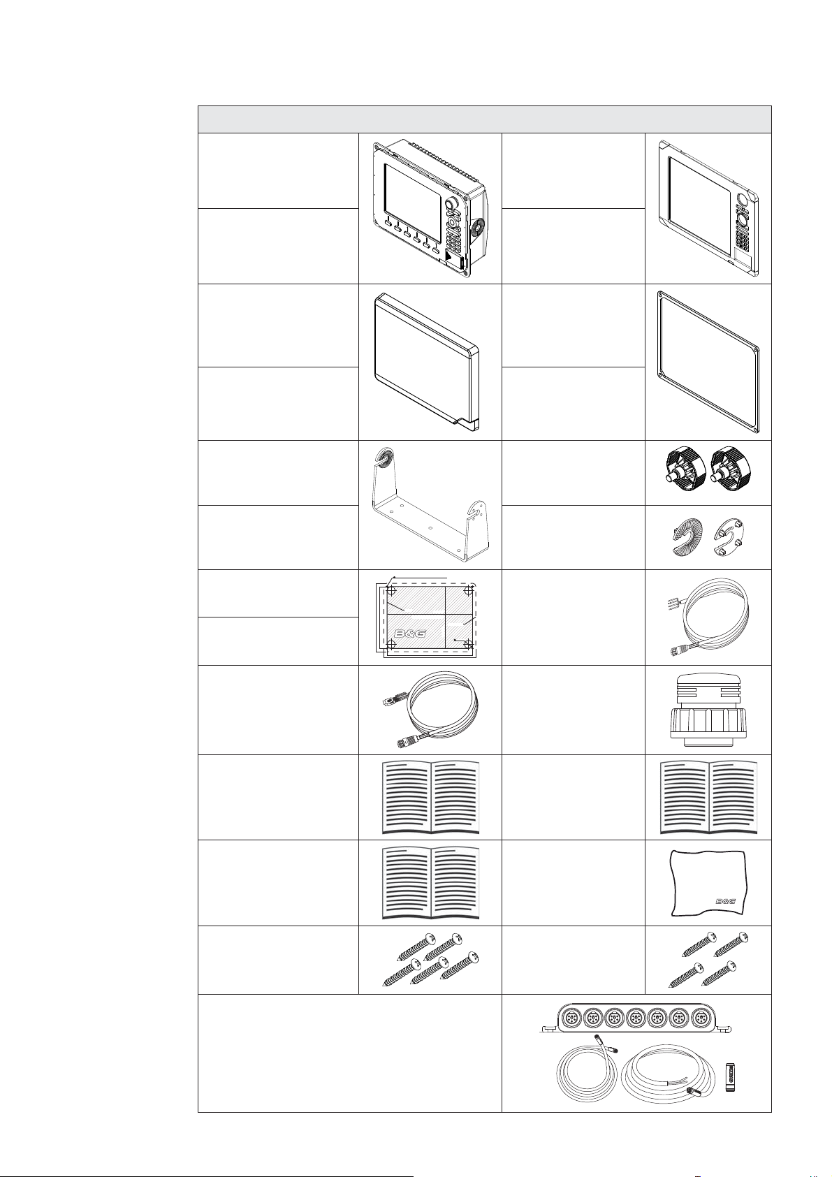
Check the Parts
Packaged Parts List
8“ Display unit
PN location specifi c
12 “ Display unit
PN location specifi c
Z8 Sun cover
000-10408-001
Z12 Sun cover
000-10407-001
Z8 Mounting bracket
000-00136-001
Z12 Mounting bracket
000-00137-001
Z8 Bezel
000-10406-001
Z12 Bezel
000-10405-001
Z8 Gasket
Z12 Gasket
Bracket knobs
000-00138-001
2 x Ratchet washers
Z8 Mounting Template
988-0186-03
Z12 Mounting Template
988-0186-04
Video-In / Comms
Cable
000-00129-001
Z8, Z12
Installation Manual
988-0186-01
Z8, Z12
Quick start guide
988-0186-02
5 x SCREW,14G x
1,PAN POZI,S/T,SS
316,BLACK
212 mm (8.34”)
192 mm (7.55)
5 mm (0.20”)
CLEARANCE HOLE TO SUIT M4 MACHINE SCREW
OR DRILL PILOT HOLE TO SUIT SELF TAPPING SCREW
CUTOUT
Check dimensions before cutting
265 mm (10.40”)
285 mm (11.20)
265 mm (10.40”)
PRODUCT OUTLINE
192 mm (7.55”)
25 mm (1.00”)
Power cable
000-00128-001
Connector Caps
000-00130-001
Operation manual
988-0186-00
Cleaning cloth
4 x SCREW,
8Gx1, PAN POZI,
S/T,16,LO-HEAD
SimNet Starter Kit: Includes
• 24005845 SimNet 5 m (16.5 ft) cable
• 24006298 SimNet 7-Prong Multi-Joiner
• 24005894 SimNet Termination Plug
• 24005902 SimNet 2 m (6 ft) power cable
w/terminator
Introduction | 7
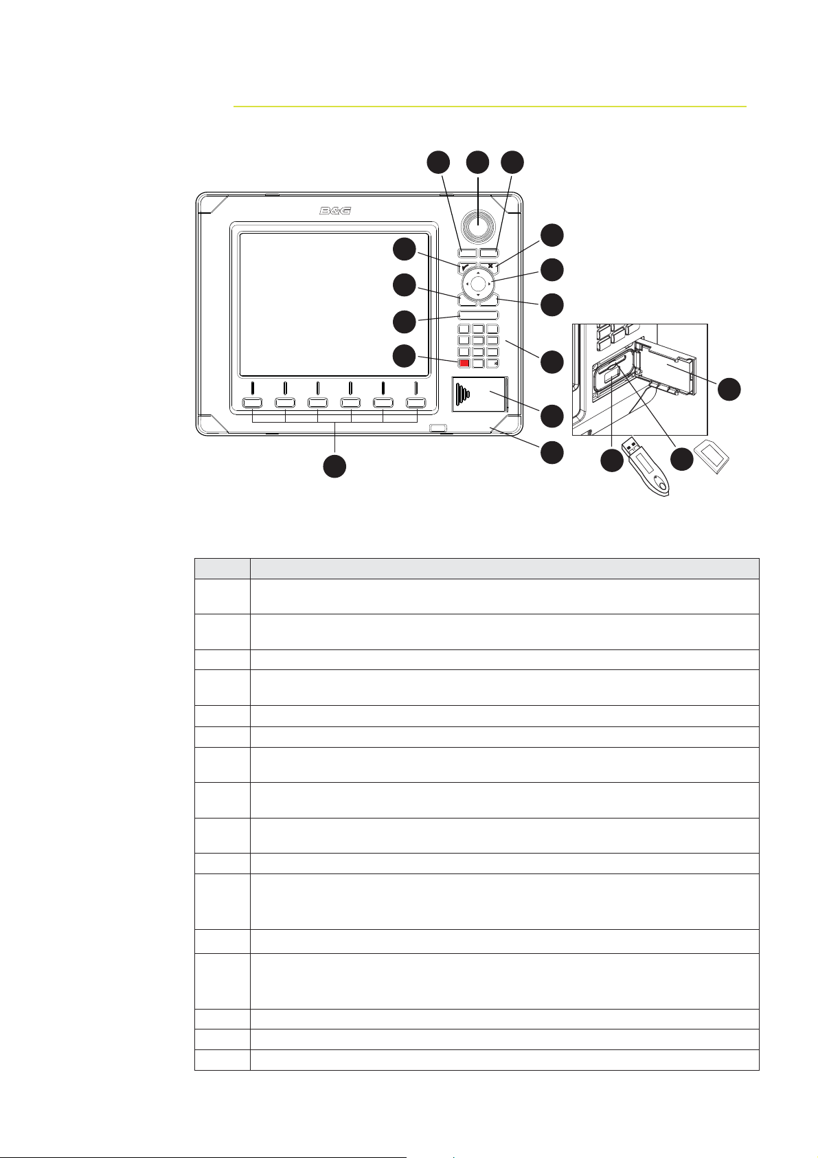
Overview 4.
2 4
3
PLOT
5
GO TO
MARK
VESSEL
7
8
6
MENU
10
12
ECHORADARCHART NAV INFO PAGES
WIN
IN
OUT
MOB
ABC DEF
123
JKLGHI MNO
456
TUV
PQRS
WXYZ
7
809
STBY
PWR
AUTO
9
11
13
16
1
15
Key Description
Direct Access Keys (DAK). Provide direct access to a page. Repeated presses
1
of each DAK cycles through several different pages that relate to the DAK
PLOT/MARK key. A short press activates the Plot menu, a long press positions
2
a waypoint at the vessel position
3 Rotary knob. The function of the knob is depending on active context
GOTO/VESSEL key. A short press activates the Goto menu, a long press
4
centers the chart to vessel position
5
3 key — Activates/confi rms current selection
6 X key cancels changes and returns to previous menu level
Cursor keypad used to move the cursor on the display, and to maneuver in the
7
menu system
MENU key. Used to display the context menu for the active panel/overlay, and
8
for selecting options in edit mode. . 2 x MENU for system settings menu
WIN key, used on multiple panels pages. A short press toggles between the
9
panels, a long press expands active panel to a full page panel and back again
10 Zoom buttons for radar, echosounder and chart pages
Alpha numeric keypad used for entering numbers and text in dialog boxes.
11
A long press on the “1” key will position a Man Over Board (MOB) waypoint at
the vessel’s current position
12 STBY AUTO - Future use
Media port door. Press and slide to the right to open.
13
Media can be used for optional Navionics chart data, software updates,
transfer of user data and system backup
14 SD /MMC media card slot.
15 USB por t
16 Removable bezel
13
14
8 | Overview
4
1 2 5 63
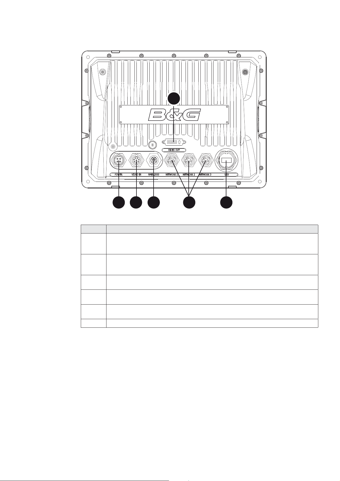
Key Description
Power. For power input 12 or 24 V DC input (see power section), Power
1
control (see Power Control section) and external alarm (see External
Alarm section.
Video In. Supplied cable provides two composite video inputs (see Video In
2
section) and one RS422 port (NMEA0183 TX, RX) see NMEA0183 Wiring
section.
SimNet. Connects Zeus display to a SimNet or NMEA2000 network (see
3
SimNet section).
Video Out. Connect to an external monitor via optional DVI cable (see Video
4
Out section).
Network 1, 2 and 3. Three Ethernet network ports for connecting to other
5
Zeus displays and Network modules. (see Ethernet section)
6 USB. Used for H-Link Communications
Overview | 9

Installing the Display 5.
Mounting location
Choose the mounting locations carefully before you drill or cut. The display should be
mounted so that the operator can easily use the controls and clearly see the display
screen. Be sure to leave a direct path for all of the cables. The display screen is highcontrast and anti-reflective, and is viewable in direct sunlight, but for best results install
the display out of direct sunlight. The chosen location should have minimal glare from
windows or bright objects.
Ensure that any holes cut are in a safe position and will not weaken the boat’s structure.
If in doubt, consult a qualified boat builder.
At least 100 mm (4”) away from the compass, at least 300 mm (12”) away from any
radio transmitter and at least 1.2 m (4 ft) away from any antenna.
Before cutting a hole in a panel, make sure that there are no hidden electrical wires or
other parts behind the panel.
Do not mount any part where it can be used as a hand hold, where it might be
submerged, or where it will interfere with the operation, launching or retrieving of the
boat.
If bracket mounting chose a flat area where the display will not be subjected to excessive
vibration.
Leave sufficient clearance space behind the display to connect all relevant cables.
Good ventilation is required behind the mounting panel. Poor ventilation may cause the
display to overheat. The display is designed to operate in temperatures from -15° C to
+55° C (+5° F to +131° F).
For overall width and height requirements, please see the drawings at the back of this
manual.
10 | Installing the Display
Panel Mount
s
5 mm (0.20”)
CLEARANCE HOLE TO SUIT M4 MACHINE SCREW
OR DRILL PILOT HOLE TO SUIT SELF TAPPING SCREW
212 mm (8.34”)
192 mm (7.55)
CUTOUT
265 mm (10.40”)
Check dimensions before cutting
265 mm (10.40”)
285 mm (11.20)
192 mm (7.55”)
PRODUCT OUTLINE
25 mm (1.00”)
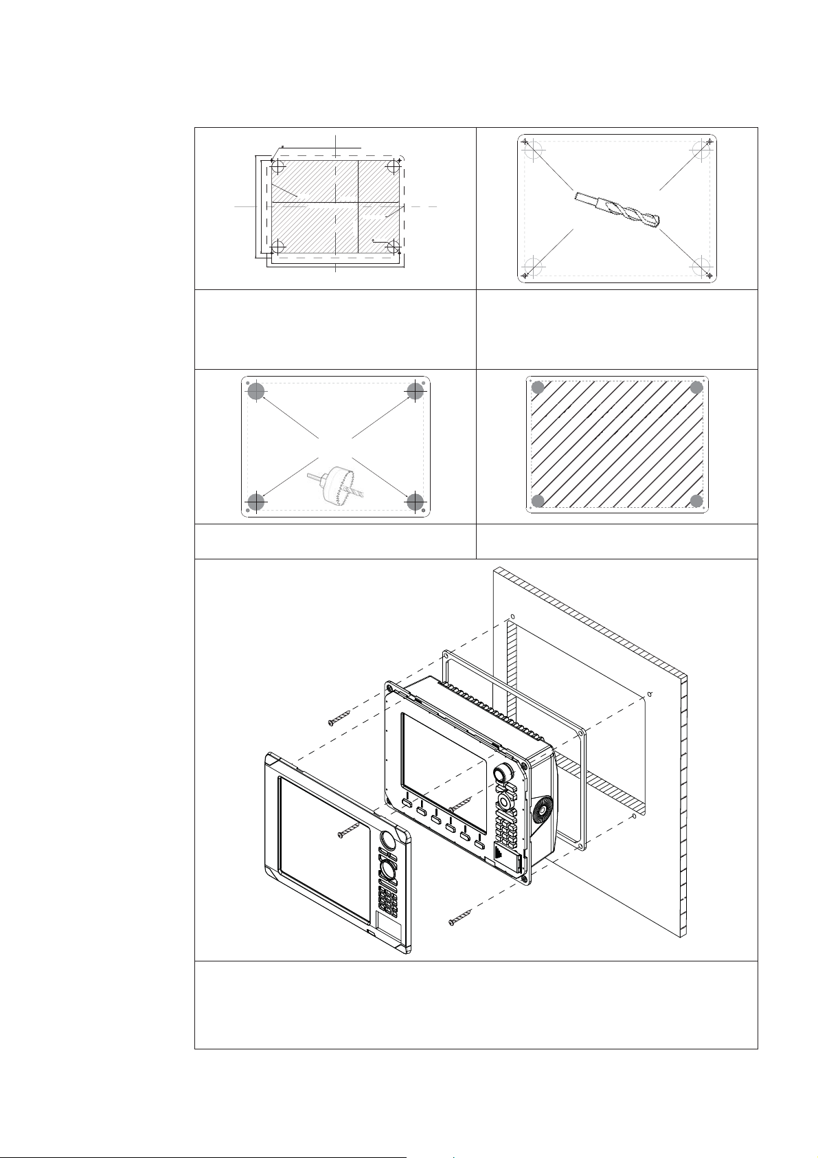
Attach the fl ush mounting template 1
to the selected mounting position
using adhesive tape.
A
Use a 25mm (1 “) hole saw to cut 3
the four corner radius
Drill pilot holes for the four hole saw 2
cuts and four self tapping screws
used to secure the display. If using
M4 machine screws use a 5 mm
(0.20 ”) drill bit.
Cut out shaded
area
Cut along the dotted line and 4
remove the shaded area.
Peel backing off the gasket and apply to the surface. 5
Connect all cables to the rear of the unit before placing the unit into the console. 6
Secure the display to the surface7
To fi nish off the installation fi rmly clip the front bezel in place8
Installing the Display | 11
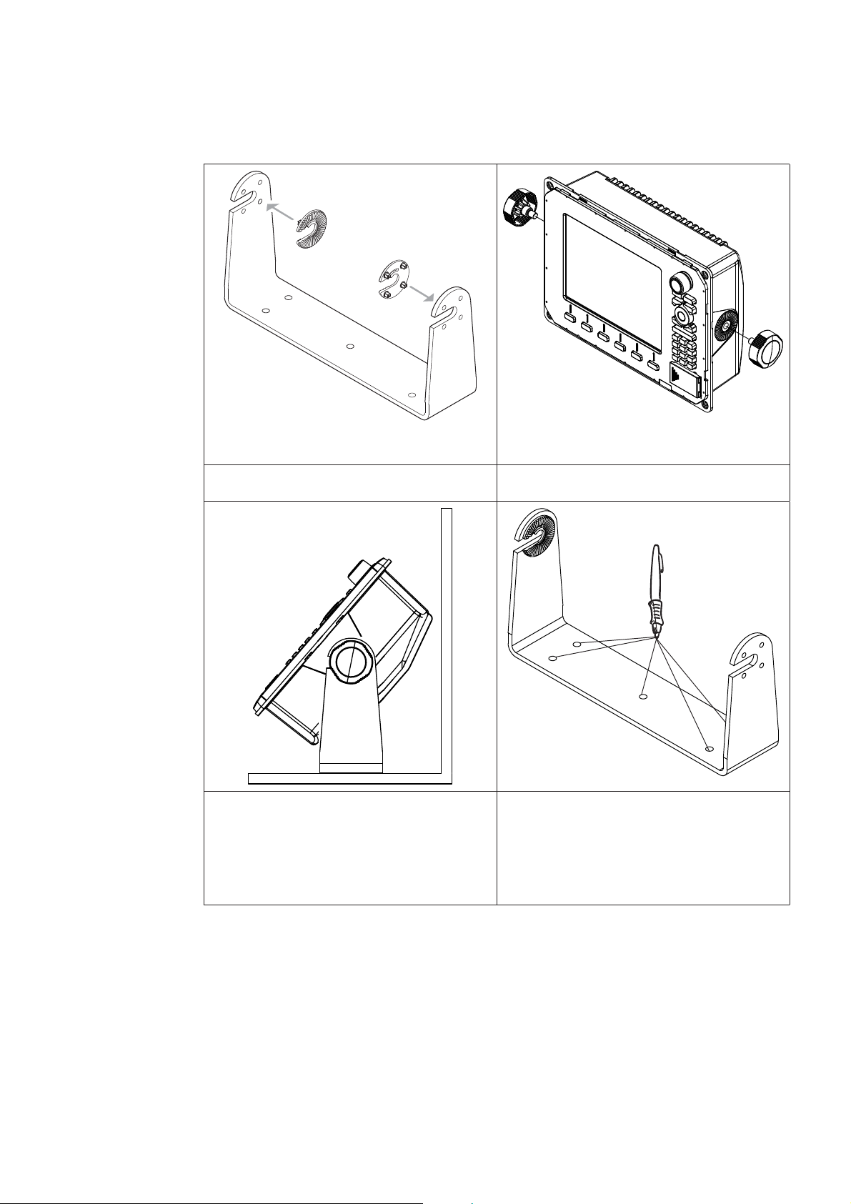
Bracket Mount
An alternative to flush mounting the Z8 or Z12 is to bracket mount the unit. This method
has the advantage that the display can easily be removed when not in use. The display
may be tilted for best possible viewing angle when bracket mounted.
Press the ratchet washers into the 1
bracket.
Temporarily mount the display 3
unit in the bracket and make sure
the display can be adjusted to the
correct angle without interfering
with the surrounding. Allow space
for cables attached to the rear of
the unit.
Loosely screw securing knobs to the 2
Display unit.
Remove the display unit and use the 4
mounting bracket as a template to
mark the fi ve positions of the screw
holes.
12 | Installing the Display
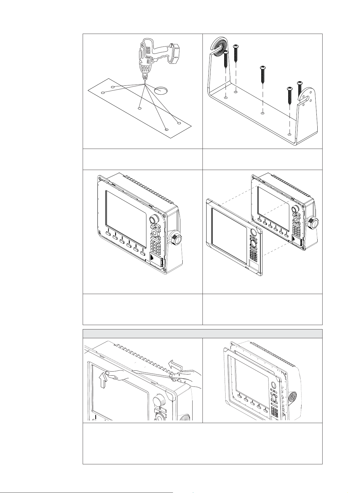
Drill a pilot hole for the fi ve screws 5
and an optional hole large enough
for the cables to emerge from.
Secure 5 the bracket to the surface6
Connect the cables.7
Slide the display into the mounting 8
bracket and secure in place with the
bracket knobs.
Zeus Bezel Removal
Attach the bezel. Firmly clip the 9
front bezel in place.
C
B
A
Protect the dash area adjacent to the top edge (or bottom edge) of the display.
Apply upwards pressure on the bezel (A), this will create an opening between the
bezel and the case. Insert a medium size fl at blade screw driver into the gap (B) Slide
the screw driver along the gap to release the clips along the top. Continue down the
side until the bezel releases. The same routine can be applied to the bottom edge if
accessible.
Installing the Display | 13

System Architecture 6.
This section explains how the Zeus connects to other devices as part of a system. The
Zeus has a highly scalable system architecture. A system can consist of a basic stand
alone chart plotter, or expand to a networked, multi-display system connected to a wide
range of accessories.
The system architecture is modular with a wide range of peripherals and accessories
that can be connected to SimNet or NMEA2000 devices such as instrument systems,
AIS, GPS and heading sensor to Ethernet devices such as Radar and Echosounder. For
multi display installations the system can be set up to be truly masterless, i.e. have no
dependency on other displays being powered on.
A Zeus display can connect to other devices in the system by Ethernet, SimNet /
NMEA2000 or NMEA0183.
A system can have:
between one and six displays, the displays can be any mix of Z8 and Z12 •
one or two radars •
one echosounder •
one StructureScan •
Networking, Data Interfacing
The Zeus system can use four data protocols. SimNet (NMEA2000), Ethernet, NMEA0183.
and H-Link.
SimNet / NMEA 2000
SimNet is a proprietary CAN bus network for transfer of navigation data such as wind, •
Position, AIS, etc between all SimNet or NMEA2000 devices on a SimNet/NMEA2000
network.
SimNet is lower bandwidth than the Ethernet network, but is 50 times faster than •
NMEA0183
Ethernet: (NETWORK ports)
Zeus uses an Ethernet network for the transfer of high bandwidth data between other •
Zeus displays and from network modules such as Radar, Echosounder and Weather
module
Each Zeus display has three Ethernet network ports. An optional 5 port expansion •
port is available. (Recommended for multiple Zeus displays)
Ethernet does not transfer navigation data such as position, heading etc. This is •
handled either by SimNet and or NMEA 0183. However navigation and display settings
are synchronized over Ethernet
NMEA0183
NMEA0183 is a point to point connection. Each Zeus display has one NMEA0183 port •
using RS422 protocol. Each display can output to one NMEA0183 “Listener” and
receive from one NMEA0183 “Talker”.
14 | System Architecture
B&G H-Link
H-Link is B&G’s protocol for comprehensive and efficient interfacing of the B&G H3000 •
processor range with the Zeus chartplotters and external PC navigation programs.
H-Link Communications are available with Zeus via USB cable. •
Data Bridging
Supported NMEA0183 sentences entering the system are bridged (converted) to •
SimNet/NMEA2000 and distributed on the SimNet backbone for all other displays to
use
Certain SimNet /NMEA2000 PGNs (messages/sentences) are bridged across to •
NMEA0183 to be available as an output from any Zeus display
Ethernet to SimNet. Limited data is bridged from the Ethernet echosounder. Speed, •
depth and temperature are bridged to SimNet and NMEA0183. Depth, speed and
temperature data from the echosounder is the only data bridged from Ethernet
DISPLAY 1
0183
RX -
NMEA0183 Talker
B
ECHORADARCHART NAV INFO PAGES
RX +
A
PLOT
MARK
MENU WIN
OUT
RANGE
MOB
123
GHI
4
PQRS
7
89
STBY
0
AUTO
GPS
SimNet Network
ABC DEF
JKL
TUV
DISPLAY 2
PLOT
GOTO
VESSEL
IN
MOB
MNO
65
WXYZ
PWR
ECHORADARCHART NAV INFO PAGES
NMEA0183
MARK
MENU WIN
OUT
RANGE
MOB
123
GHI
4
PQRS
7
89
STBY
0
AUTO
ABC DEF
JKL
TUV
GOTO
VESSEL
IN
MOB
MNO
65
WXYZ
PWR
Heading
SimNet Network
TX -
TX +
NMEA0183 Listener
C
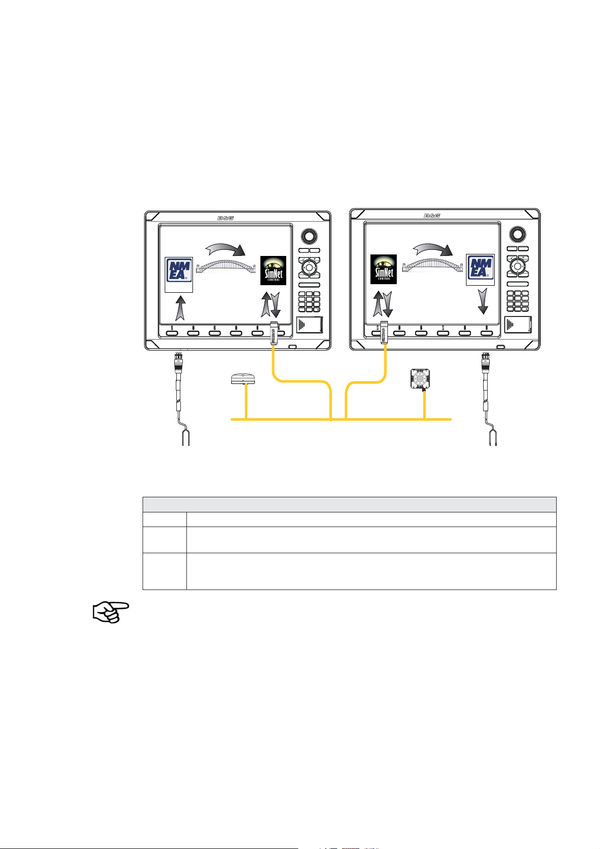
Example of Data Bridging
A In this example a NMEA0183 (talker) is connected to DISPLAY 1
B The NMEA sentences are bridged across to SimNet and distributed on the
SimNet network
C The NMEA0183 listener connected to DISPLAY 2 can receive the NMEA0183
sentences from the device connected to DISPLAY 1 and also from other
devices that are on the SimNet network
An NMEA talker can be connected to each Zeus display and both set of data will be
converted to SimNet. Each display can be setup for outputting selected NMEA sentences.
Speed, temp and depth data from the echosounder transducer that is to be displayed
as an instrument has to bridged from ethernet to SimNet. A Zeus display has to be
nominated to bridge the data. If this nominated display is turned off, no data will be
displayed, until the display is turned on or another display is selected to bridge the data
(see Source Selection).
NMEA0183 to SimNet bridging only applies to the NMEA0183 sentences outlined in the
Supported NMEA0183 Sentences section of this manual.
System Architecture | 15
Wiring Information 7.
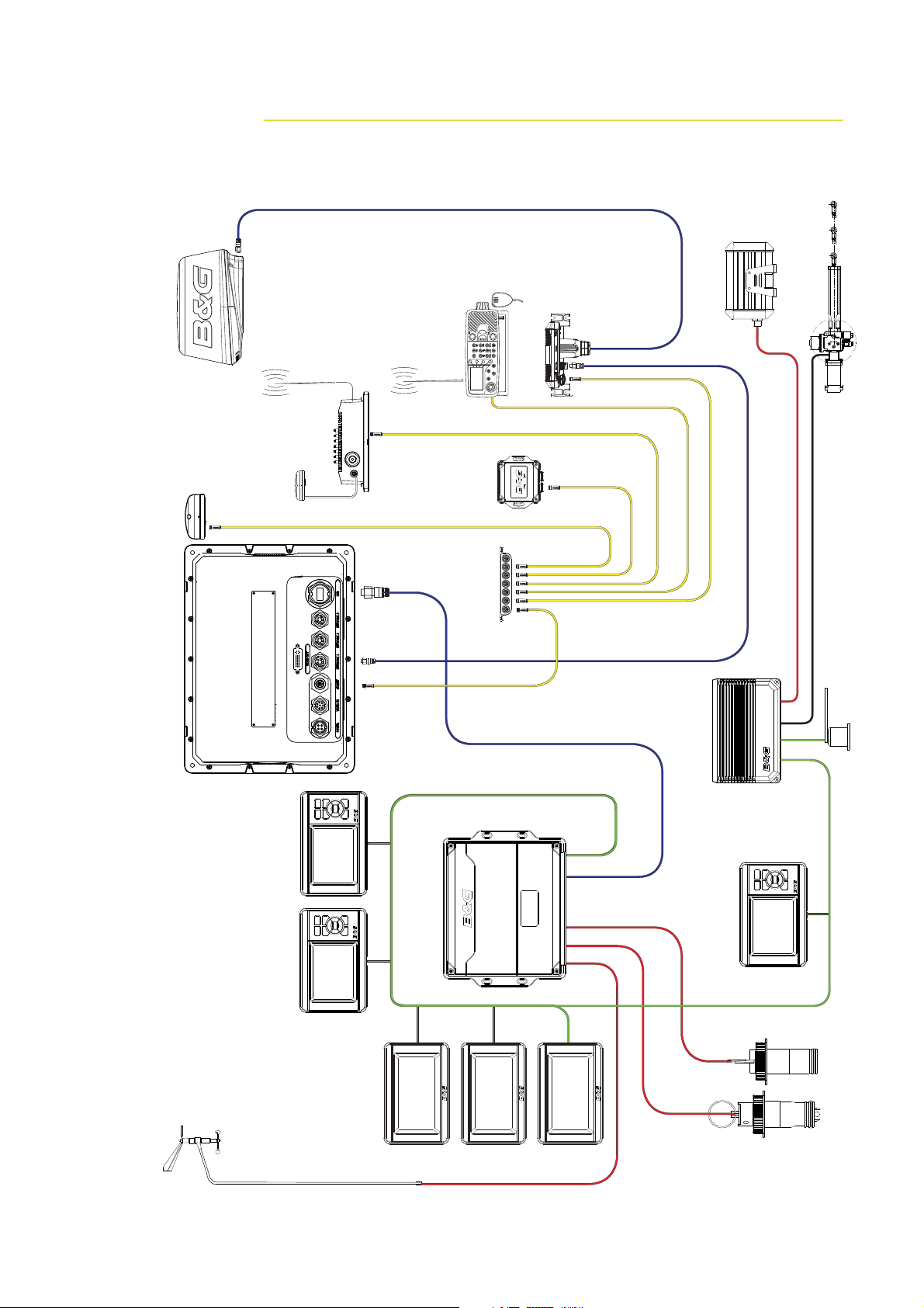
Typical System
Broadband Radar
Halcyon Gyro
Stabilised Compass
VHF Antenna
AIS
NAIS-300
Ant
GPS
ZG50
Zeus Z12
Radio
NMEA 2000
Compass
Gimballed Rate
7 way joiner
RI10
Hydraulic RAM
Sensor
Rudder
Unit
Masthead
Pilot Processor
CPU
GFD Displays
HV
Displays
20/20
H3000
H3000
GPD Display
Sensors
Speed & Depth
16 | Wiring Information

Standard Connections
NMEA0183 Devices
Zeus Display
Video / Comms - NMEA0183
H3000
NMEA0183 Device
Zeus Display H3000
H-Link (USB)
Deckman Navigation Software
Zeus Display
H3000
Deckman
Navigation Software
Video / Comms - NMEA0183
Wiring Information | 17
H-Link (USB)
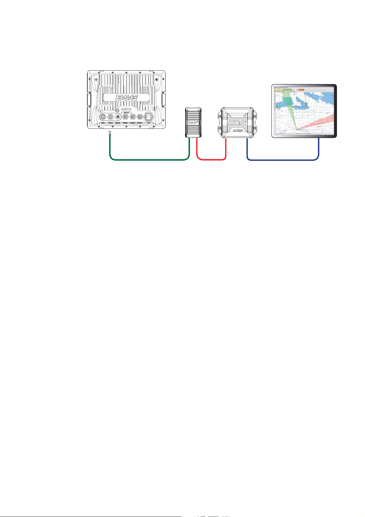
WTP3
Zeus Display
Video / Comms - NMEA0183
Serial
Interface
Can
Network
WTP3
Deckman
Navigation Software
Ethernet
18 | Wiring Information
 Loading...