


NETWORK
ACP PILOT
INSTALLATION & COMMISSIONING MANUAL
Warning: installation data included with the drive unit supersedes data in this manual
BROOKES & GATEHOUSE LTD
Premier Way
Abbey Park
Romsey
Hampshire SO51 9DH
England
Tel: (+44) 01 794 518448
Fax: (+44) 01 794 518077

SECTION 1 SYSTEM UNITS
SECTION 1 SYSTEM UNITS ................................................................ |
1 |
SITING THE ACP UNIT.................................................................. |
4 |
MOUNTING PROCEDURE ............................................................ |
4 |
ACP REMOTE COMPASS UNIT .......................................................... |
5 |
DESCRIPTION................................................................................... |
5 |
SITING THE COMPASS UNIT ....................................................... |
6 |
MOUNTING PROCEDURE ............................................................ |
6 |
NETWORK PILOT DISPLAY ................................................................ |
7 |
SITING THE PILOT DISPLAY HEAD............................................. |
8 |
MOUNTING PROCEDURE ............................................................ |
8 |
NMEA INTERFACING ....................................................................... |
9 |
NMEA INPUT ................................................................................. |
9 |
NMEA OUTPUT ........................................................................... |
10 |
HAND-HELD CONTROLLER ............................................................. |
11 |
DESCRIPTION................................................................................. |
11 |
SITING THE HAND-HELD UNIT .................................................. |
11 |
MOUNTING PROCEDURE .......................................................... |
11 |
MAN OVERBOARD BUTTON (MOB) ................................................ |
12 |
DESCRIPTION................................................................................. |
12 |
SITING THE MAN OVERBOARD ALARM BUTTON ................... |
12 |
MOUNTING PROCEDURE .......................................................... |
12 |
ACP JOYSTICK .................................................................................. |
13 |
DESCRIPTION................................................................................. |
13 |
SITING THE JOYSTICK UNIT ..................................................... |
13 |
MOUNTING PROCEDURE .......................................................... |
14 |
RUDDER REFERENCE UNIT (RRU).................................................. |
15 |
DESCRIPTION................................................................................. |
15 |
Key Points When Installing The RRU........................................... |
16 |
LINEAR FEED BACK UNIT ................................................................ |
20 |
1 - 1

ADVANCED CONTROL PROCESSOR UNIT
DESCRIPTION
The Advanced Control Processor (ACP) Unit contains all the electronics for the autopilot operation and control of the rudder drive options. It is designed to be mounted on a vertical, flat , smooth surface. The unit has a hinged lid to provide easy access to the electrical connections within. The unit requires the ACP Compass Unit (see next section).
The ACP Unit is available in two configurations:
ACP 1 |
12V only |
12 amps max. output current |
ACP 2 |
12/24V |
25 amps max. output current |
1 - 2
The 12V ACP 1 Unit will control the following rudder drive options:
• Size 1/12V Hydraulic Ram Drive |
RAM-T1-12V blue |
|
• Size 1/12V Hydraulic Pump |
PMP-T1-12V |
blue |
• 12V Rotary Drive Unit |
RDU-T1-12V |
|
• Stern Drive Unit |
SDU-T1-12V |
|
• The 24V ACP 2 unit will control the following rudder drive options:
• Size 1/12V Hydraulic Ram Drive |
RAM-T1-12V blue |
|
• Size 2/12V Hydraulic Ram Drive |
RAM-T2-12V blue |
|
• Size 3/24V Hydraulic Ram Drive |
RAM-T3-24V blue |
|
• Size 1/12V Hydraulic Pump |
PMP-T1-12V blue |
|
• Size 2/12V Hydraulic Pump |
PMP-T2-12V blue |
|
• Size 3/24V Hydraulic Pump |
PMP-T3-24V |
blue |
• 12V Rotary Drive Unit |
RDU-T1-12V |
|
• 24V Rotary Drive Unit |
RDU-T3-24V |
|
• Stern Drive Unit |
SDU-T1-12V |
|
1 - 3

SITING THE ACP UNIT
•It is recommended that the ACP unit is mounted with the cable entry points downwards. It must not be mounted with the cable entries uppermost as water may run down the cables and into the unit.
•Ensure that there is sufficient space to allow the unit to be hinged open to make connections to terminals inside, and that the hinges of the two halves of the case may be slid apart.
•Select a position sheltered from the direct effects of the environment and from physical damage.
•Do not mount the unit within 1m/3ft of engines, starter motors and cables, and other cables carrying heavy current, etc., or 3m/10ft of Radar or SSB installation cables.
MOUNTING PROCEDURE
•Undo the two screws at the corner of the unit, and open fully.
•The hinges are designed to come apart. This enables the electronics to be split from the base of the unit i.e. the connection and terminal blocks.
•Disconnect the cables between the two halves of the casing.
•Firmly push the two halves of the computer unit apart.
•Using the base of the unit as a template, mark the positions of the three mounting screw holes.
•Using the self-tapping screws provided secure the base of the unit in position.
•Push the two halves of the unit together again and reconnect the cables.
1 - 4
ACP REMOTE COMPASS UNIT
DESCRIPTION
IMPORTANT NOTE: This external fluxgate compass unit can ONLY be used with ACP Pilot Systems or Network Compass displays. Remove the transit screw after mounting on bulkhead and before inserting cable connector.
The ACP Remote Compass Unit is a gimbal mounted electronic fluxgate for use with ACP Pilot Systems. The unit is housed in a sealed casing constructed of high impact plastic. It is therefore suitable for on or below deck mounting.
If installed in a vessel with a steel or reinforced concrete hull it may be necessary to install the external compass unit outside the magnetic screening affect of the hull and super-structure.
It is supplied with a 12m/36ft, 6-core screened cable, one end with a sealed connector for the compass unit and the other connecting directly into the ACP Unit.
1 - 5

SITING THE COMPASS UNIT
•Mount the unit upright on a flat, vertical bulkhead.
•A safe distance from external magnetic interference:
•1m/3ft from VHF, RDF, loudspeakers, depth sounders, engines, power cables carrying heavy current, etc.,
•3m/10ft from Radar and SSB Equipment.
•Reasonably well protected from direct physical damage.
•With the connector downwards as shown in the above diagram.
MOUNTING PROCEDURE
•Secure the unit in the selected site using the non-magnetic selftapping screws provided.
•Route the cable to the computer unit avoiding other cables carrying heavy currents, e.g. engine starter, trim tab, etc.
•Secure in place with cable clips or tie-wraps.
•Avoid bending the cable through a tight radius especially near the connector as this may damage the wires inside the cable.
1 - 6
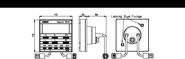
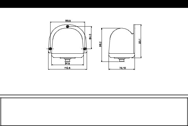
NETWORK PILOT DISPLAY
DESCRIPTION
The Network Pilot Display is designed to be mounted above or below deck. The display head allows control of the autopilot and by installing multiple display heads, gives control at any station. It can be connected to all other Network Instruments via the network cable tails to provide an integrated autopilot and navigational system. It is essential that the autopilot is initialised before operation, details are given in the commissioning section of this manual.
In an integrated system boat speed is supplied from Network SPEED or QUAD units and wind speed and wind angle from Network WIND via the system network for Steer to Compass and Steer to Vane modes.
Boat speed can also be set using the display head when required. When a GPSPlus is included in the system all required data is carried to
the Pilot via the network cable connection. Without a GPSPlus on the system, NMEA 0183 (v1.5) data can be input to the Pilot via the 3 pin socket located on the rear of the display unit.
The display heads are supplied with a clip-in mounting bracket which allows for easy installation, access from behind is not necessary to secure the unit in place. However to prevent theft or if removal of the unit is not required then locking studs and thumb-nuts are supplied to allow for permanent fixing.
1 - 7

SITING THE PILOT DISPLAY HEAD
All Network Instruments are designed for mounting on or below deck. Select a display site that is:
•At a convenient position within easy reach of the helmsman
•On a smooth and flat surface
•At a compass safe distance 100mm (4")
•Reasonably well protected from physical damage
•Accessible from behind for fitting locking studs if required
•The rear boss of the unit has a breather hole to prevent condensation, protect the rear cover from direct splashes of water.
MOUNTING PROCEDURE
•Use the cutting template supplied to mark the centres of the holes for the self-tapping screw, the fixing stud holes and the mounting bracket.
•The template allows 4mm (5/32") between adjacent units or 118mm/ 4 11/16” between centres for the suncover. Increase this distance if required to maximum of 60mm (2 3/8") between units or 180mm (7 1/8") between centres.
•For greater distances between units extension cables are available.
•Use a 70mm (2 3/4") diameter hole-cutter for the mounting bracket hole.
•Use a 2.9mm(1/8”) drill for the self-tapping screws.
•Use a 5mm (3/32") drill for the locking stud holes.
•Secure the mounting bracket to the bulkhead with the self-tapping screws supplied.
•Fit the rubber sealing gasket around the mounting bracket.
•Screw the locking studs into the back of the display head.
•Carefully pass the cable tails through the mounting bracket hole, connect the power, interconnecting and NMEA input cables to the display head (if fitted).
1 - 8

•Clip the display head into the mounting bracket.
•Secure the display head with the thumb nuts supplied (if required).
NMEA INTERFACING
The Network PILOT can be interfaced to any NMEA 0183 (v1.5) compatible position fixer. If more than one source of NMEA data is to be used then it will be necessary to use two Network PILOT display units.
NMEA INPUT
The Network PILOT display head has an NMEA input connector at the rear, use a special 3m NMEA input cable 612-OA-053 (Red sig+, Blue sig-).
The Network PILOT uses the follow data from NMEA:
Cross Track Error (XTE), Speed Over Ground (SOG), Bearing: current position to destination waypoint, Bearing: origin waypoint to destination waypoint, Distance: current position to waypoint
Waypoint number
The following NMEA sentences are decoded, Note $ID is any NMEA talker:
$IDAPA |
XTE, bearing origin to destination waypoint |
$IDAPB |
XTE, bearing origin to destination waypoint, |
|
bearing to waypoint |
$IDRMB |
XTE, bearing and distance to waypoint |
$IDXTE |
XTE |
$IDVTG |
Speed over Ground |
$IDBWR |
Bearing and Distance to waypoint rhumb, |
|
waypoint number |
$IDBWC |
Bearing and Distance to waypoint great circle, |
|
waypoint number |
1 - 9
NMEA OUTPUT
NMEA output is via the network cable connection tail, use a special 3m NMEA output cable 610-OA-030 (Red sig+, Blue sig-).
Dependent on system devices, the following sentences are transmitted:
$IIHDM |
Heading |
$IIVHW |
Speed and heading |
$IIDBT |
Depth below transducer |
$IIVWR |
Apparent wind angle and speed |
$IIMTW |
Water temperature |
1 - 10
HAND-HELD CONTROLLER
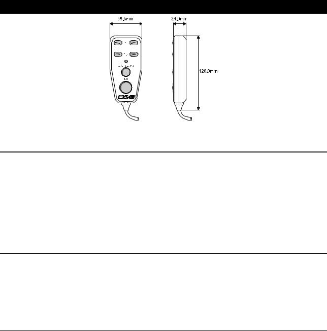
DESCRIPTION
The hand-held remote controller is a waterproof unit that has six function buttons and a status LED to indicate the operating mode of the autopilot. The unit provides palm-of-the-hand control of the PILOT. The cable has a 10 metres /30ft straight section, plus a coiled length that extends from 1 metre to 3 metres.
SITING THE HAND-HELD UNIT
•At a convenient position within easy reach of the helmsman.
•Ensure at all times the hand-held remote controller's cable does not become snagged on any moving parts e.g. throttle controls.
MOUNTING PROCEDURE
•Heavy duty self-adhesive Velcro strip is supplied with the unit.
•Clean and de-grease the site, stick the Velcro firmly in place.
1 - 11

MAN OVERBOARD BUTTON (MOB)
DESCRIPTION
The man overboard alarm button (MOB) is a large red waterproof switch with 15 metres/45ft of two-core screened cable. This button starts the MOB sequence of operations when pressed and the audible alarm sounds (if fitted).
SITING THE MAN OVERBOARD ALARM BUTTON
• Select a suitable bulkhead, easily accessible in an emergency.
MOUNTING PROCEDURE
•With a 32mm (1 1/4") hole-cutter cut a clearance hole for the button body.
•Remove the nut and washer, then ensuring the sealing gasket is in place to prevent leakage, carefully feed the cable through the hole.
•From behind the bulkhead, fit the washer and nut and tighten.
1 - 12

ACP JOYSTICK
DESCRIPTION
The joystick allows direct control of the vessel's rudder via the autopilot control electronics. The unit is deck-mountable, allowing it to be used inside or outside the steering positions. A 10m/30ft 6-core screened cable connects the unit directly into the ACP Units terminals.
Joystick steering is engaged and disengaged with the separate red button. The lever can only be moved to port or to starboard.
SITING THE JOYSTICK UNIT
• At a convenient position within easy reach of the helmsman.
1 - 13

MOUNTING PROCEDURE
•To ensure correct steering sense the unit is marked with two indents, the unit must be installed with these forward.
•The unit requires at least 65mm/2.5" clearance behind the selected mounting position.
•Use a 40mm (1 9/16th") hole cutter for the joystick body.
•Ensure the gasket is fitted under the joystick body flange.
•Secure in place with self-tapping screws.
•Route the cable to ACP unit. Connect as per instruction in Section 4 of this handbook.
For details on how to install the controller button refer to the MOB section.
1 - 14
RUDDER REFERENCE UNIT (RRU)
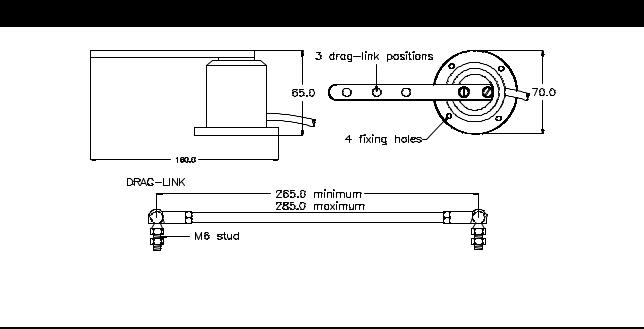
DESCRIPTION
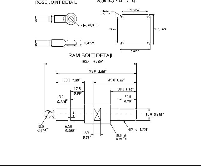
The Rudder Reference Unit (RRU) is a sealed high specification potentiometer in a robust casing, providing rudder position information to the Computer Unit. The operating arm is constructed in aluminium with three positions pre-drilled for the adjustable drag-link. The drag-link, has ball-joints at each end that connect the unit operating arm to the tiller arm or steering quadrant. The unit base has four holes to allow for mounting. The unit is supplied with 10 m/30ft of 3-core screened cable.
1 - 15

KEY POINTS WHEN INSTALLING THE RRU
•General consideration must be given to the steering system and its geometry before starting the RRU installation. Many factors must be contemplated for a practical solution, the information given here is for guidance only, although where a maximum or a minimum value is given these must be adhered to.
•Mount the RRU on a flat surface next to the tiller arm or steering quadrant, construct a small platform if necessary.
•Do not lengthen the drag-link arm as this can transmit excessive vibration loads to RRU and will invalidate the warranty.
•The unit operating arm can be rotated through 360º, the mid-point of the RRU travel is when the operating arm is opposite the cable entry point.
•When the rudder is moved from hard-over port to hard-over starboard the RRU arm should swing through a minimum of 90º, this will ensure that there is sufficient voltage output to the autopilot. Measure the voltage difference between the green and blue wires of the RRU, there should be a minimum of 1 volt change from hard over to hard over. N.B. If there is less than 1 Volt change the Pilot will not commission.
•After installation check full movement of the steering system ensuring that there is no fouling between the steering gear, RRU parts and ram drive unit if fitted.
•Ensure that there is no backlash in the linkage between the RRU and the steering gear, otherwise incorrect operation of the autopilot will occur.
1 - 16
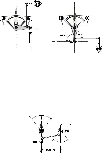
The example shown is a plan view of a typical system with a tiller arm and quadrant. When viewed in elevation, the ram drive arm and rudder reference unit drag-link must not be more than ±9º from horizontal. Ideally everything should be horizontally aligned, this prevents excessive stress during operation.
1 - 17

1 - 18
The RRU can be mounted in many different positions and orientations depending on the layout of the steering system.
If the maximum rudder angle is less than 90º then the position of the RRU or the drag-link must be adjusted so that the operating arm of the RRU swings through a minimum of 90º and the output voltage difference is greater than 1 volt from port to starboard lock. Measure the output of the RRU between the green and blue wires. N.B. If there is less than 1 Volt difference the Pilot will not commission.
1V MINIMUM VARIATION
90° MINIMUM RRU ANGLE
1 - 19
The rudder hard over angle should only be limited by the rudder stops and not the RRU linkage. Check that when hard over the RRU arm and drag-link, do not form a straight line. If this occurs the steering system could become damaged or jammed endangering the boat and crew. Rectify this immediately by adjusting the position of the RRU.
LINEAR FEED BACK UNIT
Where installation of the conventional Rudder Reference unit is difficult or physically impossible a Linear Feedback unit can be used. The Linear Feedback unit comprises of a tube approximately 23mm/ 7/8” in diameter and 324mm/ 12 3/4” long. This assembly is clamped to the side of the Linear actuator using a special bracket kit. The Linear Feed Back shaft is attached to the tiller bracket using the pin supplied with all Blue rams.
This unit requires careful installation and alignment which should be carried out by your dealer / supplier. For electrical connection see section 4.
1 - 20
SECTION 2 RUDDER DRIVE OPTIONS
RAM DRIVE UNIT __________________________________2
DESCRIPTION _____________________________________2
BLUE RAMS(DRIVE DATA) __________________________2
SIZE 1 & 2 HYDRAULIC DRIVE PUMP DIMENSIONS _____6
RAM DRIVE UNIT INSTALLATION _____________________7 Key Points On Installation ___________________________8 A Typical Ram Drive Unit Layout (REFER TABLE 2-5) _____9 Ram Mounted Parallel To Vessels Centre-Line __________10 KEY POINTS ON INSTALLATION. ___________________11 MOUNTING A BLUE RAM ON A VERTICAL BULKHEAD__11
SPLITTING THE RAM DRIVE UNIT ____________________13
BLUE HYDRAULIC DRIVE PUMPS ___________________14
DESCRIPTION ____________________________________14 Pump Data ______________________________________14 Key Points On Installation __________________________15
HYDRAULIC DRIVE PUMP DIMENSIONS ______________ 16
HYDRAULIC DRIVE PUMP INSTALLATION EXAMPLES__19
2 - 1

RAM DRIVE UNIT
DESCRIPTION
A compact DC driven reversible hydraulic pump and hydraulic cylinder assembly for boats without hydraulic steering systems. Three sizes of ram drive are available giving a wide thrust range to suit all sizes and types of vessel.
BLUE RAMS(DRIVE DATA)
Type 1 and type 2 rams combine motor, pump and hydraulic cylinder as one unit referred to as an actuator. Type 3 rams are supplied split into a separate motor/pump unit, reservoir and hydraulic cylinder, connected by 1 metre/ 3ft hoses. Longer hoses are available, contact your dealer. The units can also be mounted on a vertical bulkhead see page 2-12.
2 - 2
RAM |
|
RAM |
SIZE1 |
RAM SIZE 1 |
RAM SIZE 2 |
RAM SIZE 3 |
DRIVE |
|
BLUE |
|
BLUE |
BLUE |
BLUE |
TYPE |
|
|
|
|
|
|
|
|
|
|
|
||
ACP UNIT |
ACP1 |
ACP2 |
ACP2 only |
ACP2 only |
||
MOTOR |
|
12V DC |
12V DC |
12V DC |
24V DC |
|
SUPPLY |
|
|
|
|
|
|
SOLENOID |
12V DC |
12V DC |
12V DC |
24V DC |
||
VALVE |
|
1.25A (max) |
1.25A (max) |
1.25A (max) |
0.8A (max) |
|
SUPPLY |
|
|
|
|
|
|
PEAK |
|
425 kg force |
680 kg |
680 kg |
1062 kg |
|
THRUST |
935 lbs-force |
force |
force |
force |
||
|
|
|
|
1496 lbs- |
1496 lbs- |
2342 lbs- |
|
|
|
|
force |
force |
force |
PEAK |
|
14A @ |
20A @ |
25A @ |
17A @ |
|
CURRENT |
12V |
12V |
12V |
24V |
||
MAXIMUM |
254mm |
254mm |
254mm |
|
||
STROKE |
10" |
10" |
10" |
305mm |
||
|
|
|
|
|
|
12 " |
FULL |
|
1208 mmsq, |
1208 mmsq, |
1208 mmsq, |
1885 mmsq, |
|
BORE |
|
1.872 |
"sq |
1.872 "sq |
1.872 "sq |
2.921 "sq |
AREA |
|
1005 |
1005 |
1005 |
1570 |
|
ANNULUS |
mmsq, |
mmsq, |
mmsq, |
mmsq, |
||
AREA |
|
1.558 "sq |
1.558 "sq |
1.558 "sq |
2.434 "sq |
|
ROD |
|
16 mm, |
16 mm, |
16 mm, |
20 mm, |
|
DIAMETER |
0.623 " |
0.623 " |
0.623 " |
0.623 " |
||
TILLER |
|
214 mm |
214 mm |
214 mm |
257 |
|
ARM |
700 |
8.4 " |
8.4 " |
8.4 " |
mm |
|
for |
|
|
|
|
10.16 " |
|
rudder |
|
|
|
|
|
|
MAXIMUM |
892 Nm |
1427 Nm |
1427 Nm |
2688 Nm |
||
TORQUE |
7867 lb.ins |
12574 lb.ins |
12566 lb.ins |
23780 lb.ins |
||
WEIGHT |
7 kg, |
7 kg, |
7 kg, |
10.3 kg, |
||
|
|
15 lbs 6oz |
15 lbs 6oz |
15 lbs 6oz |
22lbs 11oz |
|
HELM |
TO |
|
|
|
|
|
HELM TIME |
15.7 sec |
15.7 sec |
11.9 sec |
14.6 sec |
||
extend |
|
|||||
retract |
|
13.4 sec |
13.4 sec |
10.2 sec |
12.6 sec |
|
|
|
(8Kg force) |
(8Kg force) |
(200Kg |
(200Kg |
|
|
|
|
|
|
force) |
force) |
The following table may be used to determine the steering system geometry for different maximum rudder angles and ram type. The last three columns show the peak torque available (in Kgm), amidships position and at the maximum rudder angle, with the latter two with the motor running at 50% duty cycle.
Refer to the diagrams on page 2-6, 2-10, 2-11, 2-13.
2 - 3
RAM-T1-12V |
|
midstroke = |
505mm |
ACP1 only |
d= |
73.3 |
1/2 max |
Tiller arm |
Offset |
Thrust |
Torque at |
Torque at |
Torque |
rudder angle |
mm |
mm |
(peak |
midships |
midships |
(at max ° |
a |
b |
c |
Kgf) |
(peak Kgm) |
(50% Kgm) |
50% Kgm) |
25 |
290 |
272 |
425 |
123 |
123 |
118 |
30 |
245 |
227 |
425 |
104 |
104 |
90 |
35 |
214 |
196 |
425 |
91 |
91 |
74 |
40 |
190 |
172 |
425 |
81 |
81 |
62 |
45 |
173 |
155 |
425 |
74 |
74 |
52 |
50 |
160 |
142 |
425 |
68 |
68 |
44 |
RAM-T1-12V |
|
midstroke = |
505mm |
ACP2 only |
d= |
73.3mm |
1/2 max |
Tiller arm |
Offset |
Thrust |
Torque at |
Torque at |
Torque |
rudder angle |
mm |
mm |
(peak |
midships |
midships |
(at max ° |
a |
b |
c |
Kgf) |
(peak Kgm) |
(50% Kgm) |
50% Kgm) |
25 |
290 |
272 |
680 |
197 |
197 |
179 |
30 |
245 |
227 |
680 |
167 |
167 |
144 |
35 |
214 |
196 |
680 |
145 |
145 |
119 |
40 |
190 |
172 |
680 |
129 |
129 |
99 |
45 |
173 |
155 |
680 |
118 |
118 |
83 |
50 |
160 |
142 |
680 |
109 |
109 |
70 |
RAM-T2-12V |
|
midstroke = |
505mm |
ACP2 only |
d= |
73.3mm |
1/2 max |
Tiller arm |
Offset |
Thrust |
Torque at |
Torque at |
Torque |
rudder angle |
mm |
mm |
(peak |
midships |
midships |
(at max ° |
a |
b |
c |
Kgf) |
(peak Kgm) |
(50% Kgm) |
50% Kgm) |
25 |
290 |
272 |
680 |
197 |
128 |
116 |
30 |
245 |
227 |
680 |
167 |
108 |
94 |
35 |
214 |
196 |
680 |
145 |
95 |
77 |
40 |
190 |
172 |
680 |
129 |
84 |
64 |
45 |
173 |
155 |
680 |
118 |
77 |
53 |
50 |
160 |
142 |
680 |
109 |
71 |
45 |
RAM-T3-24V |
|
midstroke = |
690mm |
ACP2 only |
d= |
51mm |
1/2 max |
Tiller arm |
Offset |
Thrust |
Torque at |
Torque at |
Torque |
rudder angle |
mm |
mm |
(peak |
midships |
midships |
(at max ° |
a |
b |
c |
Kgf) |
(peak Kgm) |
(50% Kgm) |
50% Kgm) |
25 |
350 |
326 |
1062 |
372 |
372 |
337 |
30 |
295 |
271 |
1062 |
313 |
313 |
271 |
35 |
257 |
233 |
1062 |
273 |
273 |
223 |
40 |
230 |
206 |
1062 |
244 |
244 |
187 |
45 |
210 |
186 |
1062 |
223 |
223 |
157 |
50 |
193 |
169 |
1062 |
205 |
205 |
131 |
2 - 4

RAM DRIVE UNIT DIMENSIONS - BLUE SIZE 1 AND 2 ACTUATORS AND BLUE RAMS.
2 - 5

SIZE 1 & 2 HYDRAULIC DRIVE PUMP DIMENSIONS
PUMP AND RAM DRIVE UNIT DIMENSIONS - BLUE SIZE 3 (REFERTO TABLE 2-5)
2 - 6
RAM DRIVE UNIT INSTALLATION
General consideration must be given to the steering system and its geometry before starting the installation. Many factors must be contemplated for a practical solution, the information given here is for guidance only, although where a maximum or minimum value is given this must be adhered to. It is essential that the unit is only installed in a fully functional steering system, with no backlash or stiffness when operating. Rectify any steering problems before installation of the ram drive unit or the autopilot will not function correctly.
2 - 7

KEY POINTS ON INSTALLATION
•Check that the steering gear is in good condition. Rectify any steering defects prior to installation of the ram.
•The ram drive unit must be secured onto a flat, rigid base, it maybe necessary to construct a platform section for the mounting plate. For angled rudder stocks an angled platform section will have to be constructed.
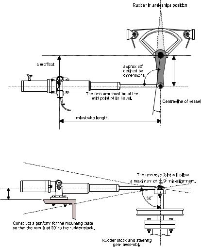
•All setting up and aligning of the ram drive unit with the steering system should be carried out with the rudder in the amidships position and the ram arm at the centre point of its travel.
•The angle between the ram arm and the tiller arm should be as shown in the next two diagrams.
•The ram arm should ideally be at right-angles to the rudder stock. The ball-joint on the end of the ram arm will allow a MAXIMUM of ±9º of misalignment.
FOR TYPE 3 RESERVOIR INSTALLATION
Do not turn the black reservoir tap on or attempt to move the piston rod until all of the following are completed:
•The base foot of the ram and pump have been bolted into position.
•The reservoir has been fixed to a bulkhead above the ram and pump.
•The sealed reservoir transit cap has been replaced by the breather cap supplied.
•The reservoir has been filled with the oil supplied.
•The reservoir tap has been switched to the ‘ON’ position allowing the oil to flow between the reservoir and the pipe.
(TAP ‘ON’ POSITION IS IN LINE WITH THE PIPE)
2 - 8
A TYPICAL RAM DRIVE UNIT LAYOUT (REFER TABLE 2-5)
b = tiller arm length
a=half max rudder angle 
d
2 - 9
 Loading...