


Triton
Operation Manual
ENGLISH
bandg.com

Preface
As Navico are continuously improving this product, we retain the right to make changes to the product at any time which may not be reflected in this version of the manual. Please contact your nearest distributor if you require any further assistance.
It is the owner’s sole responsibility to install and use the instrument and transducers in a manner that will not cause accidents, personal injury or property damage. The user of this product is solely responsible for observing safe boating practices.
NAVICO HOLDING AS AND ITS SUBSIDIARIES, BRANCHES AND AFFILIATES DISCLAIM ALL LIABILITY FOR ANY USE OF THIS PRODUCT IN A WAY THAT MAY CAUSE ACCIDENTS, DAMAGE OR THAT MAY VIOLATE THE LAW.
Governing Language: This statement, any instruction manuals, user guides and other information relating to the product (Documentation) may be translated to, or has been translated from, another language (Translation). In the event of any conflict between any Translation of the Documentation, the English language version of the Documentation will be the official version of the Documentation.
This manual represents the product as at the time of printing. Navico Holding AS and its subsidiaries, branches and affiliates reserve the right to make changes to specifications without notice.
Copyright
Copyright © 2012 Navico Holding AS.
Warranty
The warranty card is supplied as a separate document.
In case of any queries, refer to the brand web site of your display or system: www.bandg.com
About this manual
This manual is a reference guide for operating the B&G Triton instrument and Pilot controller. It assumes that all equipment is installed and configured, and that the system is ready to use.
The manual assumes that the user has basic knowledge of navigation, nautical terminology and practices.
Important text that requires special attention from the reader is emphasized as follows:
¼¼ Note: Used to draw the reader’s attention to a comment or some important information.
 Warning: Used when it is necessary to warn personnel that they should proceed carefully to prevent risk of injury and/or damage to equipment/personnel.
Preface | Triton Operation Manual |
| 1 |
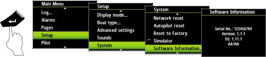
The software
This manual is written for B&G Triton Release to Market 2 (RTM2). Please check web site for details on the current release version.
¼¼ Note: The menu route shown above is an example only and may not match the software installed on your unit!
¼¼ Note: To update the software you will need a compatible multifunction display / chartplotter running on the network. eg. B&G Zeus multi function display (MFD). If you do not have a suitable device on the network you can arrange to update the software via a B&G dealer.
You can download the latest version of the software from www.bandg.com and upgrade the displays via the B&G MFD, instructions on how to do this can be found on the B&G website. www.bandg.com
¼¼ Note: The manual may have been updated to match new software releases. The latest available manual version can be downloaded from www.bandg.com
¼¼ Note: Portions of this software are copyright © 2011 The FreeType Project (www.freetype.org). All rights reserved.
2 | |
Preface | Triton Operation Manual |

Contents
5 Operation
5The Triton Display and Pilot Controller
6Pages
7Default pages
11Replacing a data page
12Template pages
13Customizing a template page
14Auto scroll
15Timer
16Log
17Alarms
20Changing an analog display scale
20Magnified wind analog display
20Rudder angle & Heel angle analog displays
21Wind Plot display
21HV display support
21Remote displays
22Configuring an HV display
23Setup
23Sources
24Device list
29Time & Date
30Units
31Display mode
31Display setup
32Show graphics
32Damping
33Decimal places
33Magnetic variation
33Sounds
34System
35Diagnostics
37 Autopilot
37 Overview
37Operation
38Pilot controller
39Turning the autopilot on / off
39Autopilot operation modes
40Autopilot symbols
40Selecting an autopilot mode
41Standby mode (Manual helm steering)
41Auto mode (Compass steer mode)
42Wind mode
43NoDrift mode
44Navigation mode (Steer to waypoint)
46Non Follow Up mode
Contents | Triton Operation Manual |
| 3 |
47 Autopilot settings
47 Installation menu
47Commissioning
48Dockside
49Rudder drive
51Sea trial
53Pilot response
54Sea state filter
54Sailing
55Automatic steering
58Reset
59 Maintenance
59 General maintenance
61 Specifications
61Technical specifications
62Dimensional drawings
62 Display
62Pilot controller
63Menu flow chart
4 | |
Contents | Triton Operation Manual |

1 |
Operation |
|
|
|
|
|
||||||
|
|
|
|
|
|
|
|
|
|
|||
The B&G Triton system is a networked multifunction instrument display and Pilot controller. |
||||||||||||
The display shows speed, depth, heading, position, wind and environmental data measured |
||||||||||||
by sensors and other equipment connected to the system. |
|
|
||||||||||
|
Navigational data, engine/battery status and vessel parameters such as accumulated log and |
|||||||||||
|
rudder angle may also be displayed. |
|
|
|
|
|
||||||
|
The instrument calculates speed trim, wind, trip distance and time, average speed, set and |
|||||||||||
|
drift parameters. A race timer is also included. |
|
|
|
|
|
||||||
|
If a compatible autopilot is installed and connected to the same network it can be controlled |
|||||||||||
|
by the Pilot controller. |
|
|
|
|
|
||||||
|
The Triton Display and Pilot Controller |
|
|
|||||||||
|
1 |
|
|
|
|
|
|
|
|
|
5 |
|
|
|
|
|
|
|
|
|
|
||||
|
|
|
|
|
|
|
|
|
|
|||
|
|
|
|
|
|
|
|
6 |
|
|
|
7 |
|
|
|
|
|
|
|
|
|
|
|
||
|
|
|
|
|
|
|
|
|
|
|
|
8 |
|
|
|
|
|
|
|
|
|
|
|
|
|
|
4 |
|
|
|
|
|
3 |
|
|
|
9 |
|
|
|
|
|
|
|
|
|
|
||||
|
|
|
|
|
|
|
|
|
||||
|
|
|
|
|
|
2 |
|
|
|
|
||
|
|
|
|
|
|
|
|
|
|
|||
1 |
Display |
|
|
|
|
|||||||
|
|
|
|
|
||||||||
2 Menu / Enter key |
|
|
|
|
|
|||||||
|
Used to enter the main menu, select sub menus and confirm selection. |
|
|
|||||||||
¼¼ Note: Press and holding the Enter key for 3 seconds takes you directly to the display setup lighting level screen. If the lighting level is set below 5 it will automatically increase to 5. Use the up and down keys to set the desired level and press Enter to confirm.
3 Page key
Scrolls through the eight default display pages and navigates back a step in menus.
¼¼ Note: the eight default display pages including Pilot page can be customized to display the required data.
4Directional keys
Scrolls up and down through selected menus / set values.
5Pilot Controller
6Mode key
Changes the Pilot mode.
7STBY key
Disengages the autopilot.
8Course control keys
Changes target course / Activates Non Follow Up (NFU) mode when in Standby mode.
9Auto key
Engages the autopilot.
Operation | Triton Operation Manual |
| 5 |

Pages
From new the display shows eight default data pages. Data pages show a variety of boat data and information available from sensors and devices on the Network.
The display default pages show: Basic speed/depth, wind composite, basic wind/speed, steering, depth history, GPS, highway and autopilot.
Each press of the page key will change the current data page to the next preselected page in the cycle.
¼¼ Note: Pressing the page key will change the data pages in sequence and in continuous rotation.
You can choose to have up to eight pages as part of the data page cycle, these can be any combination of the eight default and nine template pages available from the pages menu.
¼¼ Note: Only seven pages will be available when in Instrument Only display mode. ¼¼ Note: Two or more pages need to be enabled for the page key to function.
6 | |
Operation | Triton Operation Manual |

Default pages
Basic Speed / Depth
Two line data display. Boat speed and Depth
Wind Composite
The wind composite page presents the following information:
1 |
|
|
|
|
|
|
|
|
|
|
|
|
|
|
5 |
|
|
|
|
|
|
|
|
|
|
|
|
|
|
|
|||
2 |
|
|
|
|
|
|
|
|
|
|
|
6 |
||||
|
|
|
|
|
|
|
|
|
|
|
||||||
3 |
|
|
|
|
|
|
|
|
|
|
|
|
|
7 |
||
|
|
|
|
|
|
|
|
|
|
|
|
|
||||
|
|
|
|
|
|
|
|
|
|
|
|
|
|
|||
|
|
|
|
|
|
|
|
|
|
|
|
8 |
||||
|
|
|
|
|
|
|
|
|
|
|
|
|||||
4 |
|
|
|
|
|
|
|
|
|
|
|
9 |
||||
|
|
|
|
|
|
|
|
|
|
|
||||||
|
|
|
|
|
|
|
|
|||||||||
1Apparent wind speed (AWS)
2Red - Close hauled port tack
3Boat orientation. (Always pointing forwards)
4True wind speed (TWS)
5Apparent wind angle (AWA)
6Green - Close hauled starboard tack
7Apparent wind angle graphic
8True wind angle graphic
9True wind angle (TWA)
Basic Wind / Speed
Two line data display. Apparent Wind Angle and True Wind Speed
1
2
1Wind angle indicator - Green arrow right = Starboard tack. Red arrow right = Port tack
2Beaufort scale indicator
Operation | Triton Operation Manual |
| 7 |
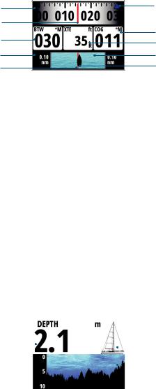
Steering
The Steering page presents the following information:
1
2
3
4
5
1Compass graphic (Heading)
2Heading
3Bearing to waypoint (BTW)
4Off track limit
5Rhumb line
6Bearing to waypoint indicator
7Course over ground (COG)
8Cross track error (XTE) R = Right / L = Left
9Cross track error graphic
10Boat position from rhumb line
Depth History
Current depth and histogram of recorded depth data.
6
7
8
9
10
1 |
|
|
|
|
|
2 |
|
|
|
|
|
||
|
|
|
|
|
||
|
|
|
|
|
|
3 |
|
|
|
|
|
|
|
|
|
|
|
|
|
|
1Depth value
2Boat type - Sail or Motor boat image
3Depth graphic
¼¼ Note: You can adjust the time period scale via the up & down keys.
8 | |
Operation | Triton Operation Manual |
GPS
The GPS page presents the following information:
2 |
|
|
|
|
|
|
|
|
|
1 |
|
|
|
|
|
|
|
|
|||
|
|
|
|
|
|
|
|
|
||
|
|
|
|
|
|
|
|
|
4 |
|
|
|
|
|
|
|
|
|
|
||
3 |
|
|
|
|
|
|
|
|
|
|
|
|
|
|
|
|
|
|
|
||
|
|
|
|
|
|
|
|
|
5 |
|
6 |
|
|
|
|
|
|
|
|
|
|
|
|
|
|
|
|
|
|
|
8 |
|
|
|
|
|
|
|
|
|
|
||
7 |
|
|
|
|
|
|
|
|
|
|
|
|
|
|
|
|
|
|
|
|
|
|
|
|
|
|
|
|
|
|
1Coordinate system
2Boat position (Latitude & Longitude)
3Course over ground (COG)
4Local time
5Speed over ground (SOG)
6Bearing to waypoint (BTW)
7Estimated time of arrival (ETA)
8Distance to waypoint (DTW)
¼¼ Note: GPS information relies on a suitable GPS connected to the network and selected on the display as the current GPS.
Highway
The Highway page presents the following information:
2
5
6
1Waypoint name
2Estimated time of arrival (ETA)
3Next waypoint
4Highway graphic
5Bearing to waypoint (BTW)
6Cross track error (XTE)
7Distance to waypoint (DTW)
1
3
4
7
Operation | Triton Operation Manual |
| 9 |
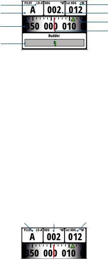
Autopilot
The Autopilot page presents the following information:
1
2
3
4
1Response mode
2Pilot mode
3Compass graphic (Heading)
4Rudder angle graphic
5Set heading / Wind angle / Rudder angle
6Current heading / Wind angle
7Set heading indicator - Green = Starboard / Red = Port
8Heading
Pilot modes
5
6
7
8
The current heading and Set heading information will change on the display depending on which mode the pilot is in. Below is a list of the pilot modes, pilot mode symbol and the current/target data that will be displayed.
1 2 3
1Pilot mode / Pilot mode symbol
2Current
3Target
Pilot Mode |
Symbol |
Current |
Target |
|
|
|
|
|
|
Standby |
S |
Heading |
N/A |
|
Auto |
A |
Heading |
Set heading |
|
Non FollowUp |
NFU |
Heading |
Rudder Angle |
|
Navigation |
N |
Heading |
Set heading |
|
Wind |
W |
True Wind Angle (TWA) |
Set Wind Angle |
|
Apparent Wind Angle (AWA) |
||||
|
|
|||
NoDrift |
ND |
Heading |
Set heading |
10 | |
Operation | Triton Operation Manual |

Response modes
The response mode is next to the Pilot mode symbol. Select auto or hi/low manual modes from the pilot response settings in the pilot menu.
Response Mode |
Symbol |
Description |
|
|
|
|
|
|
Hi-A |
When set to Auto the pilot will automatically select a |
|
Auto |
|
high or low response mode determined by boat speed |
|
Lo-A |
|||
|
and wind angle |
||
Hi |
Hi-M |
Manual selection of Hi response mode |
|
Lo |
Lo-M |
Manual selection of Lo response mode |
Replacing a data page
Go to the pages menu. Select the page you wish to replace then select the new page you would like to replace it with.
Enabling a data page
To make a data page available via the page key you will need to first ensure it has been selected as one of the eight available pages.
Once the page has been selected as one of the eight data pages you can enable it by selecting Enable Page. Once selected a tick will be visible in the check box.
Operation | Triton Operation Manual |
| 11 |

Template pages
There are several template pages that can be configured to display specific data suited to the user.
Chose from the following:
Template Page |
Symbol |
Description |
Single Line |
|
One piece of data |
Two Line |
|
Two pieces of data on a split level, top and bottom |
Four Panel Horizontal |
|
Four pieces of data. One on top and three below |
Four Panel Equal |
|
Four pieces of data. Split equally |
Nine Panel |
|
Nine pieces of data. Split equally |
Histogram |
0.0 |
Displays data as a histogram with a data value |
|
||
|
shown above |
|
|
|
|
Analog |
|
Displays data as an analog display |
Full Screen Analog |
|
Displays data as a full screen analog display |
Highway |
|
Highway graphic with three pieces of data below |
Wind Plot |
|
True Wind Speed (TWS) & True Wind Direction |
|
(TWD) data |
|
|
|
12 | |
Operation | Triton Operation Manual |
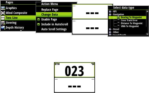
Customizing a template page
Once selected you can change the displayed data by editing the page.
Change data
You can edit a template page so it displays the specific information that you require.
¼¼ Note: A template page cannot be edited until it has been selected as one of the eight data pages.
To change the display data shown on a template page first select the template from the pages menu. In the action menu select Change Data. Highlight the desired field in the page you wish to edit and press ‘Enter’
¼¼ Note: Use the directional keys on the display to navigate between the individual data fields. Pressing the directional key in one direction will change the highlighted field in sequence and in continuous rotation.
Once the data field has been selected you can chose the data type you wish to place in this field from the menu.
Select the data type by pressing ‘Enter’ Once selected a tick will appear in the check box.
The required data will now appear in the selected field. To populate other blank fields repeat the process.
¼¼ Note: If a data type is selected but there is no sensor on the network providing the information there will be no data reading on the display. Instead there will be dashes.
¼¼ Note: Press the page key at anytime to return to the template.
Operation | Triton Operation Manual |
| 13 |
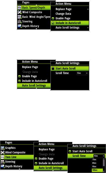
Auto scroll
When selected, auto scroll automatically scrolls between the enabled pages at a timed interval predetermined by setting the desired scroll time in the auto scroll settings menu.
Include in auto scroll
To include a page in auto scroll, go to the auto scroll settings in the action menu of the specific page and select Include in auto scroll. Once selected a tick will appear in the check box.
Auto scroll settings
In the auto scroll settings menu you can start the auto scroll function and set the time interval between page changes.
¼¼ Note: The scroll time interval can be set to change the displayed data page between 1 and 10 second intervals.
Start auto scroll
To start auto scroll, select any of the data pages from the pages menu, select Auto scroll settings and select Start auto scroll. Once selected a tick will appear in the check box and the display will scroll through the pages on a cycle set to the desired auto scroll interval. To stop auto scroll deselect Start auto scroll.
¼¼ Note: You can set the time interval of the screen transition from this menu, by selecting Scroll time and modifying the interval time.
14 | |
Operation | Triton Operation Manual |

Timer
The timer can be used as a countdown timer to a race start and as a means of measuring the time elapsed after a race start or for any other timed operation.
¼¼ Note: The timer is by default shared between interconnected displays on the network. All timer values will be identical.
The timer can be started at any time by selecting Start Timer from the timer setup menu. If the Start value is set to zero (00:00) when the timer is started the timer will begin counting up, recording the elapsed time.
¼¼ Note: The timer set value is in hours : Minutes, the timer counter will show Minutes : Seconds with the hours in the top right hand corner of the display.
Countdown Timer
If you want to count down to a race start a time value can be set in the Start Value field in the timer setup menu. When a time is present in the start value field the timer will begin to countdown from that number when the timer is started. Once the time reaches zero it will begin counting up recording the elapsed race time.
¼¼ Note: Time format = Hours (Shown in the top right-hand corner) Minutes : Seconds (MM:SS).
Start Value
To set a start value. Highlight and select Start Value. Pressing the ‘Page’ key will scroll through the race timer digits from left to right. When the desired number is highlighted, scrolling up and down will change that digit. Once complete press ‘Enter’ to confirm.
¼¼ Note: Minimum timer value greater than zero is one minute.
Start/Stop Timer
Once a start value has been set, to start the timer, highlight Start timer and press ‘Enter’. The display will turn to the timer page and begin counting accordingly. To stop the timer from counting select Timer Setup , highlight Stop Timer and press ‘Enter’.
Operation | Triton Operation Manual |
| 15 |

Reset Timer
Selecting Reset timer will reset the timer to the start value. If the timer was running, it will continue to run from the start value.
Start Trip on Running
When selected the trip log will record your time and millage from the moment the countdown clock begins counting up from zero.
Nearest Full Minute
When the timer is counting down selecting Nearest Full Minute will synchronize the time up or down to the nearest full minute.
Log
The Log page presents the following information:
1 |
|
|
|
|
|
3 |
|
|
|
|
|
||
2 |
|
|
|
|
|
4 |
|
|
|
|
|
||
|
|
|
|
|
|
|
1Current trip distance
2Current time
3Total logged distance
4Current date
The log shows the current time and date, total recorded distance for the instruments life time and trip log showing total distance travelled from the time of the trip reset and the selection of Start trip. Once started it will change to Stop trip. The trip log counter will continue to count up until it is stopped.
¼¼ Note: The Log and Date cannot be reset. The date is taken from the global time and date settings. The time can be set to correspond with your global position.
16 | |
Operation | Triton Operation Manual |
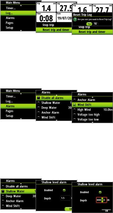
Reset trip and time
To reset the trip and time to zero select Reset trip and time.
Alarms
If you have the relevant sensor connected to the network you can enable the corresponding alarm by selecting it from the Alarms list.
Alarm on / off
Turn an alarm on or off from the alarm list. A tick symbol next to the alarm in the alarm list will indicate that the alarm is on.
¼¼ Note: It is possible to disable all alarms by selecting Disable all alarms
Setting alarm parameters
Selecting an alarm that requires parameters to be set will take you to its alarm page. Set the required parameter, select Enabled and select OK once complete.
The alarm can be disabled by deselecting Enabled.
Below is an example of how to set a shallow water alarm. Select Enabled and set the desired depth.
Operation | Triton Operation Manual |
| 17 |
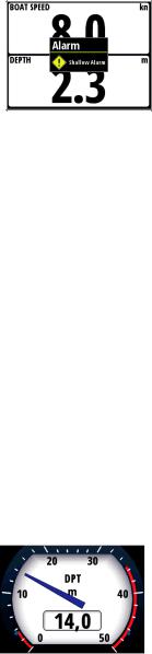
Alarm indication
The alarm system is activated if any alarm settings are exceeded.
When an alarm is notified, the alarm will be indicated with an alarm text and with an audible alarm. There are two types of audible alarm indication. Single alarm tone or continuous alarm tone.
¼¼ Note: See Alarm settings for further details on how to set an alarm.
¼¼ Note: If a Pilot is not on the network all Pilot alarms will be greyed out and will not be accessible.
If the display is connected to other Network units, any alarm in the system will be displayed on the instrument.
If no specific alarm text is displayed, an alarm code will appear.
Acknowledging an alarm
An alarm is acknowledged by pressing the ‘Enter’ key. This will remove the alarm notification (text, light and sound) from all units that belongs to the same alarm group.
A reminder will reappear at given intervals for as long as the alarm condition exists.
¼¼ Note: An alarm received from other networked units must be acknowledged on the unit generating the alarm.
Analog display alarm zones
For True Wind Speed (TWS), and deep and shallow depth alarms a red warning zone will be visible on the analog display to give you a visual indication of alarm zones.
1 |
|
|
|
|
|
2 |
|
|
|
|
|
||
|
|
|
|
|
|
|
1Shallow depth alarm
2Deep water alarm
18 | |
Operation | Triton Operation Manual |
Alarm types
Alarm |
Value |
Alarm description |
Type |
|
|
|
|
Disable all alarms |
OFF |
All alarms off.- NO Alarms will be raised! |
Cont’ |
|
|
|
|
Shallow water |
m |
Shallow water limit - Meters |
Cont’ |
|
|
|
|
Deep water |
m |
Deep water limit - Meters |
Cont’ |
|
|
|
|
High wind |
kn |
Max wind speed - Knots |
Cont’ |
|
|
|
|
Off course |
nm |
Max off course distance - Nautical miles |
Cont’ |
|
|
|
|
|
|
Use when at anchor. The alarm will sound |
|
|
|
when there is a significant change of |
|
|
|
depth caused by a change in tide or |
|
|
|
boat drifting into deeper or shallower |
|
Anchor alarm |
N/A |
water. The anchor depth alarm value is |
Cont’ |
|
|
predefined in the software and cannot be |
|
|
|
configured by the user. The anchor alarm |
|
|
|
should be turned off when the boat is not |
|
|
|
at anchor. |
|
|
|
|
|
Pilot system alarms only
Wind shift |
º |
Maximum wind shift - Degrees |
Cont’ |
|
|
|
|
|
|
Depth data missing |
N/A |
|
Single |
|
|
|
|
|
|
Wind data missing |
N/A |
|
Single |
|
|
|
|
|
|
Navigation data missing |
N/A |
Missing data |
Single |
|
|
|
|
||
Compass data missing |
N/A |
Single |
||
|
||||
|
|
|
|
|
Speed data missing |
N/A |
|
Single |
|
|
|
|
|
|
Position data missing |
N/A |
|
Single |
|
|
|
|
|
|
Rudder feedback failure |
N/A |
|
Cont’ |
|
|
|
|
|
|
Rudder response failure |
N/A |
|
Cont’ |
|
|
|
|
|
|
Drive overload |
N/A |
|
Single |
|
|
|
|
|
|
High temperature |
N/A |
|
Single |
|
|
|
|
|
|
Bypass/clutch overload |
N/A |
|
Single |
|
|
|
|
|
|
Bypass/clutch disengaged |
N/A |
Pilot failure |
Single |
|
|
|
|
||
High drive supply |
N/A |
Single |
||
|
||||
|
|
|
|
|
Low drive supply |
N/A |
|
Single |
|
|
|
|
|
|
No active control unit |
N/A |
|
Single |
|
|
|
|
|
|
No autopilot computer |
N/A |
|
Single |
|
|
|
|
|
|
ACXX Memory failure |
N/A |
|
Single |
|
|
|
|
|
|
RF must be calibrated |
N/A |
|
Single |
|
|
|
|
|
¼¼ Key: Alarm type. Single = Single sound alarm, Cont’ = Continuous sound alarm. Both types of alarm will have a notification appear on the display until the alarm is acknowledged.
Operation | Triton Operation Manual |
| 19 |
 Loading...