


 Loading...
CONTENTS
GENERAL INTRODUCTION TO B&G NETWORK 2
INTRODUCTION TO NETWORK DEPTH |
3 |
EXAMPLE SYSTEMS USING NETWORK DEPTH 4 |
|
SELECTING THE DISPLAY MODE |
5 |
USING THE DEPTH KEY |
6 |
SETTING THE DEPTH UNITS |
7 |
THE DEPTH DATUM - D CAL |
8 |
SETTING THE DEPTH DATUM |
9 |
USING THE SIGNAL KEY |
10 |
USING THE ALARM KEY |
11 |
DEPTH ALARMS |
11 |
ENABLING/DISABLING THE SHALLOW ALARM |
12 |
ADJUSTING THE SHALLOW ALARM VALUE |
12 |
ENABLING/DISABLING THE DEEP ALARM |
13 |
ADJUSTING THE DEEP ALARM VALUE |
13 |
THE ANCHOR ALARM |
14 |
ENABLING/DISABLING THE ANCHOR ALARM |
15 |
ADJUSTING THE ANCHOR ALARM LOW LIMIT |
16 |
ADJUSTING THE ANCHOR ALARM HI LIMIT |
16 |
USING THE LIGHTS KEY |
17 |
SETTING THE DISPLAY LANGUAGE |
18 |
NETWORK ALARMS |
19 |
FAULT AND ERROR MESSAGES |
20 |
INSTALLATION |
21 |
SITING THE UNIT |
21 |
MOUNTING THE UNIT |
21 |
SPECIFICATION |
23 |
CONDITIONS OF WARRANTY |
|
610-HB-0501-04 |
1 |

GENERAL INTRODUCTION TO B&G NETWORK
The B&G Network range of instruments are designed to be used as individual units or connected together to form an integrated navigational system. A single network cable is used to carry data and power between units. The latest technology and screened cables throughout the Network System ensure the ultimate protection from interference between units and other systems.
All Network instruments can be linked to Network PILOT, Network CHART, Network GPS or Network LORAN receivers or via NMEA 0183 (v1.5) to other navigational equipment.
INSTRUMENTS
Network SPEED
Network DEPTH
Network QUAD
Network WIND
Network TACK
Network DATA
NAVIGATIONAL AIDS
Network NAV
Network GPS
Network LORAN
LCD CHART
AUTOPILOTS
Network PILOT
610-HB-0501-04 |
2 |

INTRODUCTION TO NETWORK DEPTH
The Network DEPTH unit measures and displays Depth information on a large Liquid Crystal Display (LCD). The five keys allow selection of the displayed information and setting of the units mode, calibration factors and alarms.
It can operate as the main Network DEPTH unit either alone or as part of an Integrated Network Instrument System taking inputs directly from a Depth Sensor that plugs directly into the rear of the display. It will also operate as a repeater of depth information received via the two Network cable tails.
The Network Depth unit has three adjustable alarms:
1.Shallow water alarm
2.Deep water alarm
3.Anchor alarm
An internal alarm buzzer will sound when an alarm condition is met and the display will flash. The alarm is broadcast to all other Network Instruments in an integrated system, they will also sound their alarms and flash their displays (except Network WIND). The Network DEPTH unit will also indicated Network PILOT alarms and fault conditions.
610-HB-0501-04
NETWORK DEPTH DISPLAY UNIT
3

EXAMPLE SYSTEMS USING NETWORK DEPTH
Only one Network DEPTH unit should have a depth sensor connected to it and set to transducer mode. Up to three more Network DEPTH units can be connected on to the system network, these must be set to repeater mode. See SELECTING THE DISPLAY MODE.
When in repeater mode, if the data is not being received from the system network, the display will show OFF when a key is pressed.
rEP Repeater mode, the unit operates as a depth repeater using data from the system network.
610-HB-0501-04 |
4 |
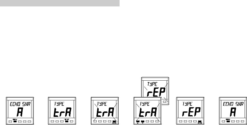
SELECTING THE DISPLAY MODE
The Network DEPTH unit has two operating modes. The correct mode must be selected for your network system to operate properly.
trA Transducer mode, the unit uses and displays depth data from a depth sensor connected directly into the display unit.
rEP Repeater mode, the unit operates as a depth repeater using data from the system network.
Press SIGNAL |
Press SETUP key |
Press ENTER key |
Use S or T to |
Press ENTER to |
Press SIGNAL |
key. |
to display the |
if the mode needs |
change mode. |
memorise the |
key to complete |
|
current mode. |
to be changed. |
|
new mode. |
the change. |
610-HB-0501-04 |
5 |
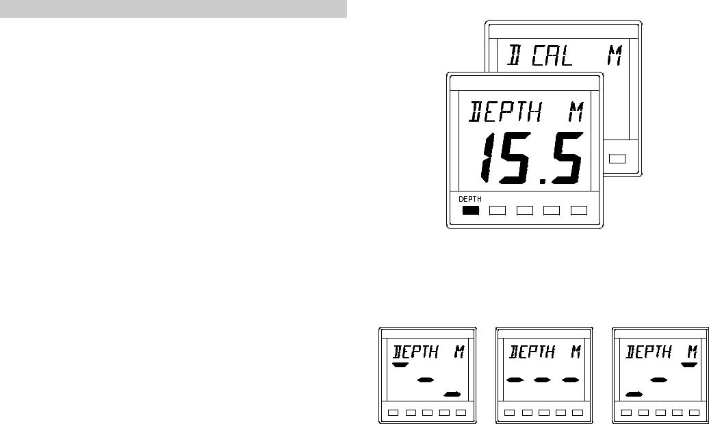
USING THE DEPTH KEY
Press the DEPTH key to cycle through the following options:
•DEPTH M The current water depth in metres M, can also be displayed in feet FT or fathoms FA. The unit is factory set to metres. The depth displayed is from the depth datum, see below.
•D CAL M The Depth Datum can be adjusted so the displayed water depth is from the waterline, the depth sensor (transducer) or the keel/outdrive depth. The unit is factory set to display water depth from the transducer.
The Network DEPTH unit can measure and display water depth in the following ranges:
•0.7 to 180 metres
•2'4" to 590'
•0.37 to 98.4 fathoms
•Accuracy ± 2% or ± 0.2m (± 8")
If the Network DEPTH unit losses valid depth data, due either the actual depth being outside the working range, or to extreme turbulence in the water the LCD will show 3 "floating" bars. This shows that the unit is attempting to calculate the depth and is still functioning.
610-HB-0501-04 |
6 |
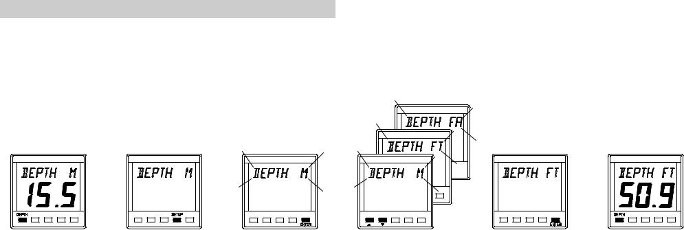
SETTING THE DEPTH UNITS
The Network DEPTH unit can be set to display depth in Metres M, Feet FT or Fathoms FA. The selected units are used for displayed depth information on all Network instruments on the entire network system.
Press DEPTH key |
Press SETUP |
Press ENTER key |
Use S or T to |
Press ENTER key |
Press DEPTH to |
to display the |
key. The depth |
if the units are to |
change the units. |
to memorise the |
display current |
current depth. |
display will go |
be changed. |
|
change. |
depth. |
|
blank. |
|
|
|
|
610-HB-0501-04 |
7 |
Loading...