


Zeus2
Operator Manual
ENGLISH
bandg.com

Preface
Disclaimer
As Navico is continuously improving this product, we retain the right to make changes to the product at any time which may not be reflected in this version of the manual. Please contact your nearest distributor if you require any further assistance.
It is the owner’s sole responsibility to install and use the equipment in a manner that will not cause accidents, personal injury or property damage. The user of this product is solely responsible for observing safe boating practices.
NAVICO HOLDING AS AND ITS SUBSIDIARIES, BRANCHES AND AFFILIATES DISCLAIM ALL LIABILITY FOR ANY USE OF THIS PRODUCT IN A WAY THAT MAY CAUSE ACCIDENTS, DAMAGE OR THAT MAY VIOLATE THE LAW.
Governing Language: This statement, any instruction manuals, user guides and other information relating to the product (Documentation) may be translated to, or has been translated from, another language (Translation). In the event of any conflict between any Translation of the Documentation, the English language version of the Documentation will be the official version of the Documentation.
This manual represents the product as at the time of printing. Navico Holding AS and its subsidiaries, branches and affiliates reserve the right to make changes to specifications without notice.
Trademarks
Lowrance® and Navico® are registered trademarks of Navico.
Fishing Hot Spots® is a registered trademark of Fishing Hot Spots Inc. Copyright© 2012 Fishing Hot Spots.
Navionics® is a registered trademark of Navionics, Inc.
NMEA 2000® is a registered trademark of the National Marine Electronics Association.
The terms HDMI and HDMI High-Definition Multimedia Interface, and the HDMI Logo are trademarks or registered trademarks of HDMI Licensing LLC in the United States and other countries.
Additional mapping data: Copyright© 2012 NSI, Inc.: Copyright© 2012 by Richardson’s Maptech.
Copyright
Copyright © 2014 Navico Holding AS.
Warranty
The warranty card is supplied as a separate document.
In case of any queries, refer to the brand website of your display or system: bandg.com
Regulatory statements
This equipment is intended for use in international waters as well as coastal sea areas administered by countries of the E.U. and E.E.A.
The Zeus2 complies with:
•CE under R&TTE directive 1999/5/EC
•The requirements of level 2 devices of the Radiocommunications (Electromagnetic Compatibility) standard 2008.
The relevant Declaration of conformity is available in the Zeus2 section on the following website: bandg.com.
Preface | Zeus2 Operator Manual |
|
3 |
|
About this manual
This manual is a reference guide for operating the Zeus2 systems. It assumes that all equipment is installed and configured, and that the system is ready to use.
The manual assumes that the user has basic knowledge of navigation, nautical terminology and practices.
Important text that requires special attention from the reader is emphasized as follows:
Ú Note: Used to draw the reader’s attention to a comment or some important information.
 Warning: Used when it is necessary to warn personnel that they should proceed carefully to prevent risk of injury and/or damage to equipment/ personnel.
Viewing the manual on the Zeus2 screen
The pdf viewer included in the Zeus2 makes it possible to read the manuals and other pdf files on the unit. Manuals can be downloaded from bandg.com.
The manuals can be read from an inserted Micro-SD card or copied to the unit’s internal memory.
Use the menu options or the keys and on-screen buttons to maneuver in the pdf file as described below:
Search, Goto page, Page |
Select the relevant panel button |
|
Up and Page Down |
||
|
||
|
|
|
Scroll pages |
Turn the rotary knob. |
|
|
|
|
Panning on the page |
Drag finger on the screen in any direction. |
|
|
|
|
Zoom In/Out |
Use pinch or spread gestures. |
|
|
|
|
Exit the pdf viewer |
Press the X key or select the X in the upper right corner of the |
|
|
panel. |
|
|
|
The software
This manual is written for the Zeus2 software version 1.5.
The manual will be continuously updated to match new software releases. The latest available manual version can be downloaded from bandg.com.
4 |
|
Preface | Zeus2 Operator Manual |
|

Contents
9 Introduction
9The front panel and keys
10The Home page
11Application pages
12Integration of 3rd party devices
13GoFreeTM wireless
13H5000 integration
13Remote controllers
14Basic operation
14Turning the unit on and off
14Display illumination
14Locking the touch screen
15Touch screen operation
16Using menus and dialogs
16Selecting pages and panels
17Positioning a Man Over Board mark
17Screen capture
18Customizing your system
18Customizing the Home page background
18Adjusting panel size
19Adding new favorite pages
19 Edit favorite pages
19Setting the appearance of the Instrument bar
20Charts
20The Chart panel
21Chart data
21Showing dual chart types
21Vessel symbol
21Chart scale
21Panning the chart
22Positioning the vessel on the chart panel
22Displaying information about chart items
23Using the cursor on the chart panel
23Saving waypoints
23Creating routes
23Measuring distance
24Find objects on chart panels
243D charts
24Chart overlay
25Insight specific chart options
25Insight view options
25Navionics specific chart options
26Navionics chart settings
26 Navionics view options
28Jeppesen tides and currents
29Chart settings
31 Waypoints, routes and tracks
31Waypoints
32Routes
35Tracks
36Waypoints, routes and tracks dialogs
Contents | Zeus2 Operator Manual |
|
5 |
|
37 Navigating
37Navigate to cursor position
37Navigate a route
37Navigating with the autopilot
38Navigation settings
40The SailSteer panel
41Selecting data fields for the SailSteer panel
41Sail Time calculations
42Time and Wind plots
42The Time plot panel
42Wind Plot panel
43Autopilot
43 Safe operation with the autopilot
43 Activating the autopilot
43 Switching from automatic mode to manual steering
43 Autopilot indication on the pages
45The Autopilot panel
45Mode overview
46Standby mode
46Non-Follow Up (NFU, Power steering)
46Follow-up steering (FU)
46AUTO mode (auto compass)
47NoDrift mode
47NAV mode
48WIND mode
49WIND Nav mode
50Turn pattern steering
51Using the Zeus2 in an AP24/AP28 system
52Using the autopilot in an EVC system
52 Autopilot settings
55 Radar
55The radar panel
55Radar overlay
56Radar operational modes
56Radar Range
56Using the cursor on a radar panel
56Saving waypoints
57Adjusting the radar image
58Advanced radar options
58Radar view options
59EBL/VRM markers
60Setting a guard zone around your vessel
61MARPA targets
62Recording radar data
62 Radar settings
64 Echosounder
64The Echosounder image
65Zooming an Echosounder image
65Using the cursor on the echosounder panel
66Saving waypoints
66 Viewing sounder history
66Setting up the Echosounder image
67Advanced Echosounder options
6 |
|
Contents | Zeus2 Operator Manual |
|
67Recording echosounder data
68Echosounder view options
69Echosounder settings
71 StructureScan™
71 The StructureScan™ image
71Zooming the StructureScan image
72Using the cursor on the StructureScan™ panel
72Saving waypoints
72Viewing StructureScan™ history
73Setting up the StructureScan image
73 Advanced StructureScan settings
75 StructureMap
75The StructureMap image
75Activating Structure overlay
75StructureMap sources
76StructureMap tips
76 Recording StructureScan data
76Using StructureMap with mapping cards
77Structure options
78AIS
78AIS target symbols
79Viewing information about AIS targets
80Calling an AIS vessel from the Zeus2
80AIS SART
81Vessel alarms
82Vessel settings
84 Instrument panels
84 Dashboards
84Customizing the Instrument panel
85Audio
85Enabling audio
86The Audio panel
87Setting up the audio system
88Operating the audio system
88Favourite channels
88Using Sirius radio (North America only)
89Weather
89 Wind barbs
89 GRIB weather
91 SiriusXM™ weather
95 Video
95 The Video panel
95Setting up the video panel
96FLIR camera control
98 Alarms
98 Alarm system
98Type of messages
98Single alarms
98Multiple alarms
99Acknowledging a message
Contents | Zeus2 Operator Manual |
|
7 |
|
99Alarms dialog
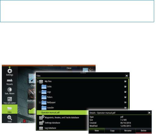
100Tools
100Waypoints/routes/tracks
100Tides
100Alarms
100Settings
100Vessels
100Sun/Moon
100Trip calculator
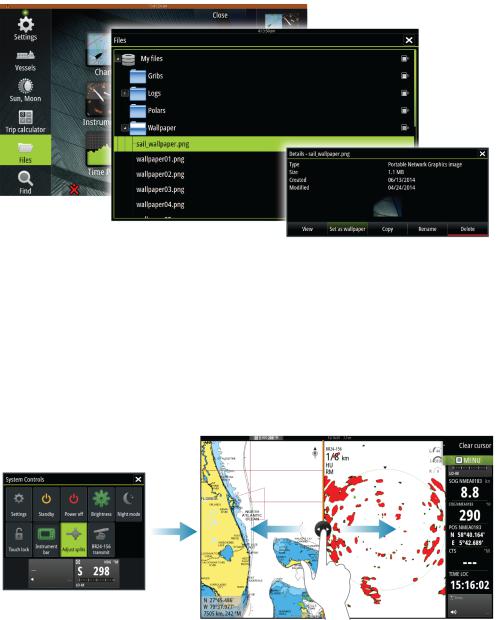
100Files
101Find
102Simulator
102 Demo mode
102Simulator source files
103Advanced simulator settings
104Maintenance
104Preventive maintenance
104Cleaning the display unit
104Cleaning the media port door
104Checking the keys
104Checking the connectors
105NMEA 0183 Data logging
105Software upgrades
106Backing up your system data
8 |
|
Contents | Zeus2 Operator Manual |
|

1 |
Introduction |
|
|
The front panel and keys |
Key |
Description |
|
|
|
|
1 |
Touch screen |
|
|
|
|
2 |
Power key |
|
|
Press once to display the System control dialog. |
|
|
Repeat short presses to cycle the backlight brightness. |
|
|
Press and hold to turn the unit ON/OFF. |
|
|
|
|
3 |
Rotary knob |
|
|
Rotate to scroll through menu items, then press to confirm a selection. |
|
|
Rotate to adjust a value. |
|
|
Rotate to zoom a zoomable panel. |
|
|
|
|
4 |
STBY / AUTO key |
|
|
With the autopilot in any automatic mode: Press to set the autopilot to Standby |
|
|
mode. |
|
|
With the autopilot in Standby mode: Press to display the autopilot mode selection |
|
|
pop-up. |
|
|
|
|
5 |
Home key |
|
|
Press once to activate the Home page. Repeat short presses to cycle the favorite |
|
|
buttons. |
|
|
Press and hold to display the Favorite panel as an overlay on active page. Repeat |
|
|
short presses to cycle the favorite buttons. |
|
|
|
|
6 |
X key |
|
|
Press once to exit a dialog, to return to previous menu level and to remove the |
|
|
cursor from the panel. |
|
|
|
|
7 |
MARK key |
|
|
With cursor active on the panel: Press to immediately save a waypoint at cursor |
|
|
position. |
|
|
With no active cursor: Press to immediately save a waypoint at vessel position. |
|
|
Press and hold to display the Plot menu used for saving new waypoints, routes and |
|
|
tracks. |
|
|
|
|
8 |
Card reader door |
|
|
|
|
9 |
Micro-SD Card readers |
|
|
|
Ú Note: The MARK key is not available on 7" units.
Introduction | Zeus2 Operator Manual |
|
9 |
|
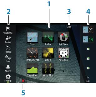
The Home page
The Home page is accessed from any operation by a short press on the Home key.
Key |
Description |
|
|
|
|
1 |
Applications |
|
|
Select a button to display the application as a full page panel. |
|
|
Press and hold a button to display pre-configured split page options for the |
|
|
application. |
|
|
|
|
2 |
Tools |
|
|
Select a button to access dialogs used for carrying out a task, or for browsing |
|
|
stored information. |
|
|
|
|
3 |
Close button |
|
|
Select to exit the Home page and return to the previous active page. |
|
|
|
|
4 |
Favorites |
|
|
Select a button to display the panel combination. |
|
|
Press and hold a favorite button to enter edit mode for the Favorites panel. |
|
|
|
|
5 |
Man Over Board (MOB) button |
|
|
Select to save a Man Over Board (MOB) marker at the current vessel position. |
|
|
|
10 |
|
Introduction | Zeus2 Operator Manual |
|
Application pages
Each application connected to the system is presented on panels. The application can be presented as a full page, or in combination with other panels in a multiple panel page.
All pages are accessed from the Home page.
Key |
Description |
|
|
|
|
1 |
Application panel |
|
|
|
|
2 |
Instrument bar |
|
|
Navigation and sensor information. The bar can be tuned off and it can be |
|
|
configured by the user. |
|
|
|
|
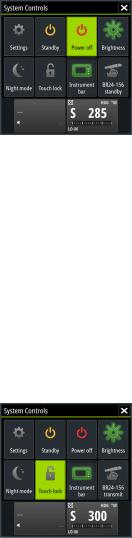
3 |
System Control dialog |
|
|
Quick access to basic system settings. |
|
|
Display the dialog by a short press on the Power key or by swiping down from top |
|
|
of the screen. |
|
|
|
|
4 |
Status bar |
|
|
|
|
5 |
Dialog |
|
|
Information to or input from the user. |
|
|
|
|
6 |
Alarm message |
|
|
Displayed if dangerous situations or system faults occur. |
|
|
|
|
7 |
Menu |
|
|
Panel specific menu. |
|
|
Display the menu by selecting the MENU panel button. |
|
|
|
Split pages
You can have several panels on one page depending on screen size:
•7" units: 2 panels
•9" and 12" units: 4 panels
2 panels page |
3 panels page |
4 panels page |
All panel sizes in a split page can be adjusted.
Introduction | Zeus2 Operator Manual |
|
11 |
|
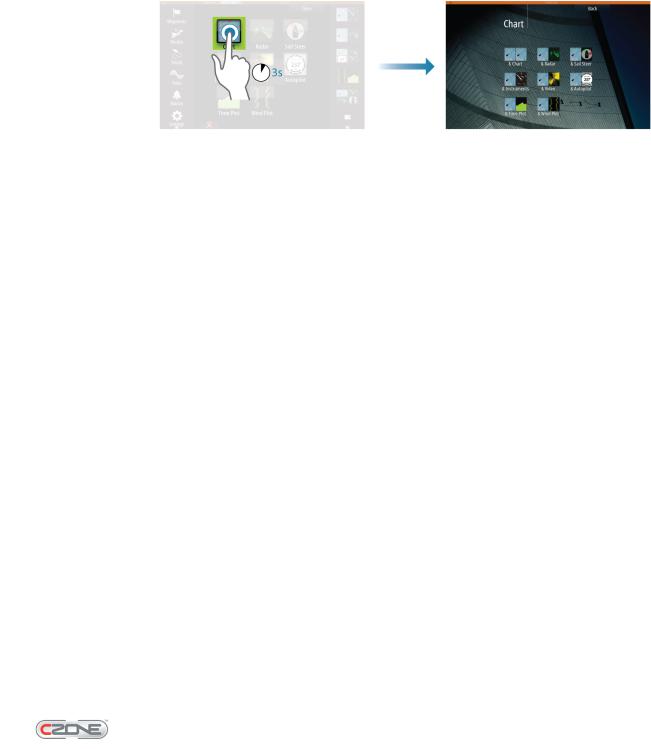
Pre-configured split pages
Each full screen application has several pre-configured split pages, featuring the selected application combined with each of the other panels.
ÚNote: The number of split pages cannot be changed, and the pages cannot be customized or deleted.
Access a split page by pressing and holding the main panel button.
Favourite pages
All preconfigured favourite pages can be modified and deleted, and you can create your own. You can have a total of 12 favourite pages.
Integration of 3rd party devices
Several 3rd party devices can be connected to the Zeus2 system. The applications are displayed on separate panels or integrated with other panels.
A device connected to the NMEA 2000 network should automatically be identified by the Zeus2. If not, enable the feature from the advanced option in the System settings dialog.
The 3rd party device is operated from the Zeus2 by using menus and dialogs as on other panels.
This manual does not include specific operation instructions for any 3rd party device. For features and functionality, refer to the documentation included with the 3rd party device.
FUSION-Link integration
FUSION-Link devices connected to the NMEA 2000 network can be controlled from the Zeus2.
The FUSION-Link devices will appear as additional sources when using the audio function. No additional icons will be available.
Refer to "Audio" on page 85 for more information.
FLIR camera integration
If a FLIR camera is available on the Ethernet network, you can display the video and control the camera from the Zeus2.
The FLIR camera is controlled from the Video panel, and no additional icons will appear on the Home page.
Refer to "Video" on page 95 for more information.
BEP CZone integration
The Zeus2 system integrates with BEP’s CZone system used for controlling and monitoring a distributed power system on your vessel.
The CZone icon will be available in the Tools panel on the Home page when a CZone system is available on the network.
A separate manual is provided with your CZone system. Refer to this documentation and to the Zeus2 Installation manual for how to install and configure the CZone system.
12 |
|
Introduction | Zeus2 Operator Manual |
|
CZone dashboard
When the CZone is installed and configured, an additional CZone dashboard will be added to the Instrument panels.
You switch between a panel’s dashboards by selecting the left and right arrow symbols or by selecting the dashboard from the menu.
Editing a CZone dashboard
You can customize a CZone dashboard by changing the data for each of the gauges. Available editing options depend on the type of gauge and which data sources that are connected to your system.
For more information refer to "Instrument panels" on page 84.
GoFreeTM wireless
With a WIFI-1 unit connected to the Zeus2 system you can use a wireless device to remotely control the Zeus2. The Zeus2 is controlled from the wireless device by Apps downloaded from their relevant Application store.
ÚNote: For security reasons, Autopilot and CZone functions cannot be controlled from a wireless device.
Installation and wiring of the WIFI-1 unit are described in the separate WIFI-1 Installation Guide. Configuration and setup are described in the Zeus2 Installation manual.
Operating the Zeus2 with a wireless device
When remote control is accepted, the Zeus2 page will be mirrored to the wireless device.
The Zeus2 image includes softkeys with the same functionality as the unit. Selecting these keys works as operating the similar hard keys on the Zeus2.
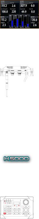
H5000 integration
The Zeus2 system integrates with B&G’s H5000 Instrument and Autopilot system.
The H5000 icon will be available in the Tools panel on the Home page when an H5000 system is available on the network.
A separate manual is provided with the H5000 system. Refer to this documentation and to the Zeus2 Installation manual for how to install and configure the H5000 system.
Remote controllers
You can connect a ZC1 to the network and remotely control the Zeus2.
A separate manual is included with the remote controller.
Introduction | Zeus2 Operator Manual |
|
13 |
|
2 |
Basic operation |
|
|
Turning the unit on and off |
|
You turn the unit on and off by pressing and holding the Power key. |
If the key is released before the shut-down is completed, the power off process is cancelled.
You can also turn the unit off from the System controls dialog. This dialog is activated by a short press on the Power key, or by swiping down from top of the screen.
ÚNote: The System controls dialog will not display the power off option when the unit is configured as slave. Refer to details in the Zeus2 Installation manual.
First time startup
The first time the unit is started and after a master reset the system will run through an automatic start-up sequence, including language setup and automatic data source selection. You can select to interrupt this sequence and later configure the system yourself.
Standby mode
In Standby mode, the backlight for screen and keys are turned off to save power. The system will continue to run in the background.
You select Standby mode from the System controls dialog.
Switch from Standby mode to normal operation by a short press on the Power key.
Display illumination
The display backlighting can be adjusted at any time from the System controls dialog. You can also cycle the preset backlight levels by short presses on the Power key.
If a ZM monitor is plugged into the HDMI output port on a 9" or 12" unit, an additional icon will be added to the System controls dialog. Select this icon to control the brightness of the
external monitor.
The night mode option optimizes the color palette for low light conditions.
Ú Note: Details on the chart may be less visible when the Night mode is selected!
Locking the touch screen
You can temporarily lock the touch screen to prevent accidental operation of the system.
This feature is also useful when cleaning the screen while the unit is turned on.
When the touch lock is active you can only operate the unit from the keys.
The touch screen operation is locked from the System controls dialog.
You remove the lock function by a short press on the Power key.
14 |
|
Basic operation | Zeus2 Operator Manual |
|
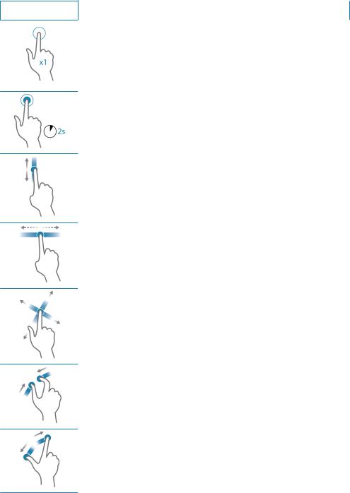
Touch screen operation
Basic touch screen operation on the different panels is shown in the table below.
The panel sections later in this manual have more information about panel specific touch screen operation.
Icon |
Description |
|
|
Tap to:
•Activate a panel on a multi-panel page
•Position the cursor on a panel
•Select a menu and a dialog item
•Toggle a checkbox option on or off
•Show basic information for a selected item
Press and hold:
•On any panel with a cursor to activate the cursor assist feature
•On a panel button to see available split screen options
•On a favorite button to enter edit mode
Scroll through a list of available options without activating any option.
Flick to quickly scroll through e.g. the waypoint list. Tap the screen to stop the scrolling.
Pan to position a chart or an echo image on the panel.
Pinch to zoom out on the chart or on an image.
Spread to zoom in on the chart or on an image.
Basic operation | Zeus2 Operator Manual |
|
15 |
|
Using menus and dialogs
Menus
You display a page menu by selecting the MENU button in the upper right corner of the page.
•Activate a menu item and toggle on/off a checkbox by selecting it
•Adjust a slide bar value by either:
•dragging the slide bar
•selecting the + or - icons
You can also operate the menus by using the rotary knob.
•Turn the knob to scroll through menu items
•Press the knob to select a highlighted item
•Turn the knob to adjust the value of a selected item
Select the Back menu option or the X key to return to the previous menu level, and then exit.
You can make the menu slide away by tapping the screen outside the menu area, or by pressing the MENU button. When you re-press the MENU button, the menu opens in the
same status it had before it closed.
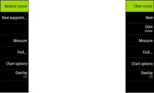
The status of the cursor (active vs. inactive) will change the menu options.
Chart menu - cursor not active |
Chart menu - active cursor |
Dialog boxes
You select entry fields and keys in a dialog box by tapping the screen or by using the rotary knob.
Numeric and alphanumeric keyboards are automatically displayed when required for
entering user information in dialogs. You operate the keyboard by selecting the virtual keys, and you confirm your entry by selecting the virtual Enter key or by pressing the rotary knob.
A dialog is closed by saving or cancelling the entry.
A dialog can also be closed by selecting the X in the dialog's upper right corner or by pressing the X key.
Selecting pages and panels
Selecting a page
•Select a full page panel by tapping the relevant application button on the Home page
•Select a favorite page by pressing the relevant favorite button
•Select a predefined split panel by pressing and holding the relevant application icon
Select active panel
In a multiple panel page only one panel can be active at a time. You will only be able to access the page menu of an active panel.
You activate a panel by tapping it. The active panel is outlined with a border.
16 |
|
Basic operation | Zeus2 Operator Manual |
|
Positioning a Man Over Board mark
If an emergency situation should occur, you can position a Man Over Board mark at the
vessel’s current position by pressing the Home key followed by the MOB button on the Home page.
When you activate the MOB function the following actions are automatically performed:
•a MOB mark is positioned at the vessel’s position
•the display switches to a zoomed chart panel, centered on the vessel's position
•the system displays navigation information back to the MOB mark
Multiple MOB marks are positioned by repeatedly pressing the MOB button. The vessel will continue to show navigation information to the initial MOB mark. Navigation to subsequent MOB marks will need to be done manually.
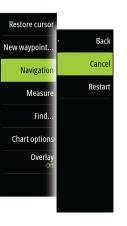
Cancel navigation
The system will continue to display navigational information towards the MOB mark until you cancel the navigation from the menu.
Delete a MOB mark
1.Select the MOB mark to activate it
2.Tap the MOB mark's pop-up or press the Enter key or the rotary knob to display the MOB mark dialog
3.Select the delete option in the dialog
A MOB mark can also be deleted from the menu when it is activated. See also "Waypoints-Routes- Tracks" on page 31.
Screen capture
Simultaneously press the Home and Power keys to take a screenshot. By default, screen captures are saved to internal memory.
Refer to "Tools" on page 100 for how to view and manage files.
Basic operation | Zeus2 Operator Manual |
|
17 |
|
3 |
|
Customizing your system |
|
|
|
Customizing the Home page background |
||
|
The Home page's background can be customized. You can select one of the pictures |
|
|
included with the system, or you can use your own picture in .jpg or .png format. |
|
The images can be available on any location that can be seen in the files browser. When a picture is chosen as the wallpaper, it is automatically copied to the Wallpaper folder.
Adjusting panel size
You can change the panel size for an active split page. The panel size can be adjusted for both favorite pages and for predefined split pages.
1.Activate the System control dialog by pressing the Power key or by dragging your finger from the top of a touch screen
2.Select the adjust splits option in the dialog
3.Adjust the panel size by dragging the adjustment icon. Confirm your changes by tapping one of the panels, by pressing the rotary knob or the Enter key
The changes are saved to the the active favorite or split page.
18 |
|
Customizing your system | Zeus2 Operator Manual |
|
Adding new favorite pages
1.Select the New icon in the favorite panel on the Home page to open the page editor dialog
2.Drag and drop page icons to set up a new page
3.Save the page layout
The display will return to the Home page, and the new page will be included in the list of favorite pages.
Edit favorite pages
1.Select the edit icon for a favorite icon to enter edit mode
-Select the cancel icon to remove a page
-Select the tools icon to display the page editor dialog
2.Add or remove panels in the page editor dialog, then save your changes
3.Press the X key to leave the favorite edit mode
Setting the appearance of the Instrument bar
Data sources connected to the system can be viewed in the Instrument bar.
You can configure the Instrument bar to display either one or two bars, or set it to alternate the bars automatically.
You can turn the Instrument bar off from the System controls dialog.
ÚNote: This only turns the Instrument bar off for the current page.
Turning the Instrument bar on/off
1.Activate the System controls dialog by pressing the Power key or by dragging your finger from the top of the screen
2.Deactivate/activate the instrument bar icon to toggle the bar on and off.
Edit the content of the Instrument bar
1.Activate the Instrument bar by tapping it
2.Select the MENU button to edit the content
3.Select the content you want to display
ÚNote: You can configure Bar 1 for active page or for all pages except those that have a local configuration. Bar 2 can only be configured for active page.
4.Define the time period if you want the two bars to alternate automatically
5.Select the edit option to change any of the instrument fields, followed by the field you want to change
6.Save your changes by selecting the finish edit option in the menu.
Customizing your system | Zeus2 Operator Manual |
|
19 |
|
4 |
Charts |
|
|
|
|
|
The chart function displays your vessel’s position relative to land and other chart objects. On |
|
the chart panel you can plan and navigate routes, place waypoints and display AIS targets. |
|
You can overlay a radar image, a StructureScan image or weather information. |
|
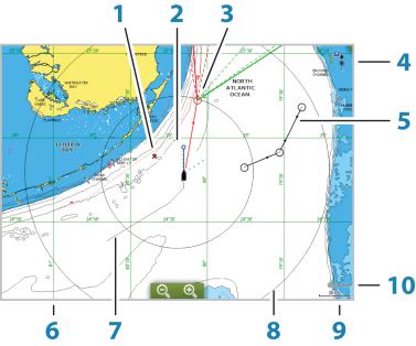
The Chart panel |
Key |
Description |
Comment |
|
|
|
|
|
1 |
MOB (Man Over Board) mark |
|
|
|
|
|
|
2 |
Vessel with extension line |
Extension line is optional |
|
|
|
|
|
3 |
Waypoint with Laylines |
* |
|
|
|
|
|
4 |
North indicator |
|
|
|
|
|
|
5 |
Route |
* |
|
|
|
|
|
6 |
Grid lines |
* |
|
|
|
|
|
7 |
Track |
* |
|
|
|
|
|
8 |
Range rings |
* |
|
|
|
|
|
9 |
Chart range scale |
|
|
|
|
|
|
10 |
Range rings interval |
Only displayed when Range |
|
rings are turned on |
|||
|
|
||
|
|
|
*Optional chart items
ÚNote: You turn the optional images on/off individually. For more information, see "Chart settings" on page 29.
20 |
|
Charts | Zeus2 Operator Manual |
|
Chart data
The Zeus2 is delivered with different embedded cartography depending on region.
All units will support Insight charts from Navico including Insight Genesis. The Zeus2 also supports Navionics Gold, Platinum+ and Navionics+, C-MAP MAX-N/MAX-N+ by Jeppesen as well as content created by a variety of third party mapping providers in the AT5 format. For a full selection of available charts please visit insightstore.navico.com, c-map.jeppesen.com or navionics.com.
Charts are shared over the network, so only one chart card per boat is required.
ÚNote: The system will not automatically switch to embedded cartography if the SD card is removed. A low-resolution chart will be displayed until you re-insert the SD card or manually switch back to embedded cartography.
Showing dual chart types
If you have different chart types available - embedded, in the card slot or on the Ethernet - you can show two different chart types simulatanously on a page with two chart panels.
You can select a dual chart panel by pressing and holding the Chart application button on the Home page, or by creating a favorite page with two chart panels.
Selecting chart type
Chart type is set individually for each chart panel.
Activate one of the chart panels by tapping it, then select one of the available chart types from the chart options menu. Repeat the process for the second chart panel, and select an alternative chart type for this panel.
ÚNote: To show charts other than Navionics, Insight chart type must be selected.
If you have identical charts available - built in, in the card slot or on the Ethernet network - the system will automatically select the chart with most chart details for your displayed region.
Vessel symbol
When a GPS and a suitable heading sensor are connected to the system, the vessel symbol indicates vessel position and heading.
Without a heading sensor fitted, the vessel icon will orientate itself using COG (Course over Ground). If no GPS is available the vessel symbol will include a question mark.
Chart scale
You zoom in and out on the chart by using the zoom panel icons, the rotary knob, or by using 2 fingers to pinch (zoom out) and spread (zoom in).
Chart range scale and range rings interval (when turned on) will be shown in the lower right corner of the chart panel.
Panning the chart
You can move the chart in any direction by dragging your finger in the desired direction.
Press the X key or select the Clear cursor menu option to remove the cursor and cursor window from the panel. This will also center the chart to vessel position.
Charts | Zeus2 Operator Manual |
|
21 |
|

Positioning the vessel on the chart panel
Chart orientation
Several options are available for how the chart is rotated in the panel. The chart orientation symbol in the panel’s upper right corner indicates the north direction.
North up |
Heading up |
Course up |
North up
Displays the chart with north upward. Corresponds to the usual orientation of nautical charts.
Heading up
Displays the chart with the vessel’s heading directed upward. Heading information is received from a compass. If heading is not available, then the COG from the GPS will be used.
Course up
Rotates the chart in the direction of the next waypoint when navigating a route or navigating to a waypoint. If not navigating the heading up orientation will be used until navigation is started.
Look ahead
Centres the chart slightly forward of your vessel so that you can maximize your view ahead.
Displaying information about chart items
When you select a chart item, a waypoint, a route or a target, basic information for the selected item will be displayed. Tap the chart item's pop-up to display all available information for that item. You can also activate the detailed information dialog from the menu.
Ú Note: Pop-up information has to be enabled in chart settings to see basic item information.
.
22 |
|
Charts | Zeus2 Operator Manual |
|
Using the cursor on the chart panel
The cursor is by default not shown on the chart panel.
When you tap on the screen, the cursor will be visible and the cursor position window will be activated. When the cursor is active, the chart will not pan or rotate to follow the vessel.
Press the X key or select the Clear cursor menu option to remove the cursor and the cursor window from the panel. This will also center the chart to the vessel position.
Select the Restore cursor menu option to display the cursor in its previous location. The Clear cursor/Restore cursor are useful features for toggling between the vessel's current
location and the cursor position.
GoTo cursor
You start navigating to a selected position on the image by positioning the cursor on the panel, then using the go to cursor option in the menu.
The Cursor assist function
When using a touch screen, the cursor assist function allows for fine tuning and precision placement of the cursor without covering details with your finger.
Press and hold your finger on the screen to switch the cursor symbol to a selection circle, appearing above your finger.
Without removing your finger from the screen, drag the selection circle over the desired item to display item information.
When you remove your finger from the screen the cursor reverts to normal cursor operation.
Saving waypoints
You can save a waypoint at a selected location by positioning the cursor on the panel, then selecting the new waypoint option in the menu.
If your unit has a MARK key, you can press this key to immediately save a waypoint. If the cursor is active the waypoint will be saved at the cursor position. If the cursor is not active the waypoint will be saved at your vessel's position.
Creating routes
You can create routes as follows on the chart panel.
1.Tap the screen to activate the cursor
2.Select New followed by New route in the menu
3.Select the position for the first route point.Tap the screen to position the first routepoint, and then continue tapping the screen to place the remaining routepoints
4.Save the route by selecting the save option in the menu
ÚNote: See "Waypoints-Routes-Tracks" on page 31 for more information.
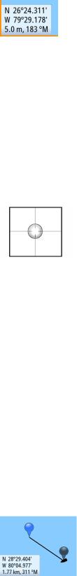
Measuring distance
The cursor can be used to measure the distance between your vessel and a selected position, or between 2 points on the chart panel.
1.Position the cursor on the point from where you want to measure the distance from the vessel
2.Start the measure function from the menu
-The measuring icons will appear with a line drawn from the vessel center to the cursor position, and the distance will be listed in the cursor information window
3.You can reposition the measing points by dragging either icon as long as the measuring the function is active
ÚNote: The bearing will always be measured from the grey icon to the blue icon.
Charts | Zeus2 Operator Manual |
|
23 |
|
You can also start the measuring function without an active cursor. Both measuring icons will then initially be located at the vessel position. The grey icon will follow the vessel as the vessel moves, while the blue icon will remain at the position given when you activated the function.
You terminate the measuring function by tapping Finish measuring or by pressing the X key.
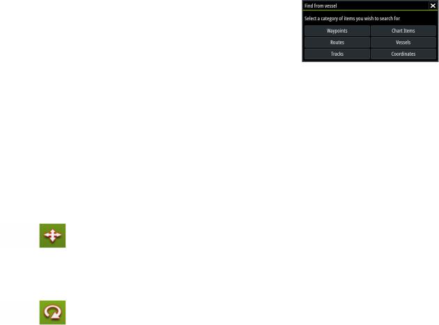
Find objects on chart panels
You can search for other vessels or various chart items from a chart panel.
Activate the cursor on the panel to search from the cursor position. If the cursor is not active the system will search for items from the vessel's position.
ÚNote: You must have a SIRIUS data package subscription to search for fueling stations and an AIS receiver connected to search for vessels.
3D charts
The 3D option provides a three dimensional graphical view of land and sea contours.
ÚNote: All chart types work in 3D mode, but without 3D cartography for the appropriate area the chart will appear flat.
When 3D chart option is selected, the Pan and the Rotate icons appear on the right side of the chart panel.
Panning the 3D chart
You can move the chart in any direction by tapping the Pan icon and then dragging your finger in the desired direction.
Press the X key or select the Return to vessel menu option to stop panning, and to center the chart to vessel position.
Controlling the view angle
You can control the view angle by tapping the Rotate icon and then dragging on the screen.
•To change the direction you are viewing, drag horizontally
•To change the tilt angle of the view, drag vertically
ÚNote: When centered on the vessel position, only the tilt angle can be adjusted. The view direction is controlled by the chart orientation setting. See "Positioning the vessel on the chart panel" on page 22.
Zooming a 3D chart
You zoom in and out on a 3D chart by using the zoom panel icons or the rotary knob.
Chart overlay
Radar, Structure, AIS and weather information can be displayed as overlay on your chart panel.
When an overlay is selected, the chart menu will be expanded to include basic functions for the selected overlay.
Radar, Structure, AIS and weather functions are described in separate sections in this manual.
24 |
|
Charts | Zeus2 Operator Manual |
|
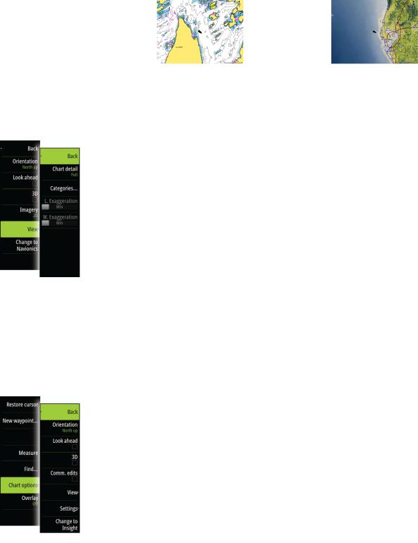
Insight specific chart options
Orientation, Look ahead, 3D and Change to Navionics/Change to Insight (previously described in this section) are common for all chart types.
Chart imagery style
The charts can be displayed in two imagery styles, 2D basic mapping and shaded relief with terrain imaging.
Insight 2D mapping style |
Insight Shaded relief |
Insight view options
Insight Chart Details
Low |
Basic level of information that cannot be removed, and includes information |
|
that is required in all geographic areas. It is not intended to be sufficient for |
|
safe navigation |
|
|
Medium |
Minimum information sufficient for navigation |
|
|
Full |
All available information for the chart in use |
|
|
Insight chart categories
Insight charts include several categories and sub-categories that you can turn on/off individually depending on which information you want to see on your display.
Land Exaggeration and Water Exaggeration
Graphical settings available in 3D mode only. Exaggeration is a multiplier applied to the drawn height of hills on land, and troughs in water to make them look taller or deeper.
Navionics specific chart options
Orientation, Look ahead, 3D and Change to Navionics/Change to Insight (previously described in this section) are common for all chart types.
Community edits
Toggles on the chart layer including Navionics edits. These are user information or edits uploaded to Navionics Community by users, and made available in Navionics charts.
For more information refer to Navionics information included with your chart, or to Navionics website: www.navionics.com.
Charts | Zeus2 Operator Manual |
|
25 |
|
Navionics chart settings
Colored Seabed Areas
Used for displaying different depth areas in different shades of blue.
Presentation type
Provides marine charting information such as symbols, colors of the navigation chart and wording for either International or U.S. presentation types.
Annotation
Determines what area information, such as names of locations and notes of areas, is available to display.
Chart details
Provides you with different levels of geographical layer information.
Safety depth
The Navionics charts use different shades of blue to distinguish between shallow and deep water.
Safety depth, based on a selected limit, is drawn without blue shading.
ÚNote: The built in Navionics database features data down to 20 m, after which it is all white.
Contours depth
Determines which contours you see on the chart down to the selected safety depth value.
Rock filter level
Hides rock identification on the chart beneath a given depth.
This helps you to declutter charts in areas where there are many rocks located at depths well below your vessel's draught.
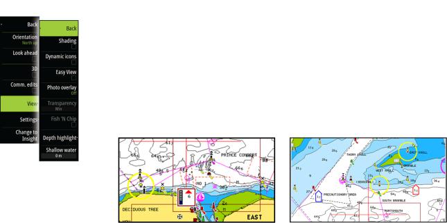
Navionics view options
Chart shading
Shading adds terrain information to the chart.
Dynamic tide and current icons
Shows tides and currents with a gauge and an arrow instead of the diamond icons used for static tides and current information.
The tide and current data available in Navionics charts are related to a specific date and time. The Zeus2 animates the arrows and/or gauges to show the tides and currents evolution over time.
Dynamic tide information |
Dynamic current information |
26 |
|
Charts | Zeus2 Operator Manual |
|

The following icons and symbology are used:
Icons Description
Current speed.
The arrow length depends on the rate, and the symbol is rotated according to flow direction. Flow rate is shown inside the arrow symbol. Red symbol used when current speed is increasing,- blue symbol when current speed is decreasing.
Tide height.
The gauge has 8 labels and is set according to absolute max/min value of the evaluated day.
Red arrow used when tide is rising,- blue arrow when tide is falling.
ÚNote: All numeric values are shown in the relevant system units (unit of measurement) set by user.
Easy View
Magnifying feature that increases the size of chart items and text.
ÚNote: There is no indication on the chart showing that this feature is active.
Photo overlay
Photo overlay enables you to view satellite photo images of an area as an overlay on the chart. The availability of such photos is limited to certain regions.
You can view photo overlays in either 2D or 3D modes.
No Photo overlay |
Photo overlay, land only |
Full Photo overlay |
Photo transparency
The Photo transparency sets the opaqueness of the photo overlay. With minimum transparency settings the chart details will be almost hidden by the photo.
Navionics Fish N' Chip
Zeus2 supports Navionics Fish N' Chip (U.S. only) chart feature.
For more information, see www.navionics.com.
Depth highlight range
Select a range of depths between which Navionics will fill with a different color.
This allows you to highlight a specific range of depths for fishing purposes. The range will only be as accurate as the underlying chart data, meaning that if the chart only contains 5 meter intervals for contour lines, the shading will round to the nearest available contour line.
Charts | Zeus2 Operator Manual |
|
27 |
|

No Depth highlight range |
Depth highlight range: 6 m - 12 m |
Shallow water highlight
Highlights areas of shallow water.
This allows you to highlight areas of water between 0 and the selected depth (up to 10 meters/30 feet).
No shallow water highlighted |
Shallow water highlight: 0 m - 3 m |
Jeppesen tides and currents
Zeus2 can display Jeppesen tides and currents. With this information it is possible to predict the time, level, direction and strenght of currents and tides. This is an important tool when considering planning and navigation of a trip.
In large zoom ranges the tides and currents are displayed as a square icon including the letter T (Tides) or C (Current). When you select one of the icons tidal or current information for that location are displayed.
Dynamic current data can be viewed by zooming inside a 1-nautical mile zoom range. At that range, the Current icon changes to an animated dynamic icon that shows the speed and direction of the current. Dynamic icons are colored in red (6 knots or higher), yellow (2 to 6 knots) or green (2 knots or less), depending of the current in that location.
If there is no current (0 knots) this will be shown as a white, square icon.
Static Current and Tide icons |
Dynamic Current icons |
28 |
|
Charts | Zeus2 Operator Manual |
|

Chart settings
Settings and display options made in the Chart settings page are common for all chart panels.
3D boat selection
Determines which icon to use on 3D charts.
Boat settings
The boat settings are used when calculating an automatic route. The boat's draught, width and height must be input to use the autorouting/easy routing features.
Range Rings
The range rings can be used to present the distance from your vessel to other chart objects. The range scale is set automatically by the system to suit the chart scale.
Vessels’ extension lines
Sets the length of the extension lines for your vessel and for other vessels shown as AIS targets.
A: Heading
B: Course Over Ground (COG)
The length of the extension lines are either set as a fixed distance, or to indicate the distance the vessel will move in the selected
time period. If no options are turned on for This vessel then no extension lines will be
shown for your vessel.
Your vessel heading is based on information from the active heading sensor and COG from active GPS sensor.
For other vessels COG data is included in the message received from the AIS system.
Charts | Zeus2 Operator Manual |
|
29 |
|
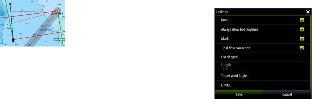
Laylines
Configures the options for laylines on the chart and on the SailSteer panels.
The image shows laylines from mark/ waypoint with limits.
The following settings are available:
Boat |
Displays laylines from boat, indicating the |
|
target course |
|
|
Always show boat laylines |
Displays boat laylines |
|
|
Mark |
Displays laylines from mark/waypoint, |
|
indicating the target course to sail to reach |
|
the mark/waypoint |
|
|
Tidal flow correction |
Calculates the tidal effect of the boat based |
|
on COG, and applies this information to the |
|
laylines. |
|
|
Overlapped |
Extends the laylines beyond the tack/gybe |
|
intersection |
|
|
Length |
Sets the length of the laylines |
|
|
Target wind angle |
Defines the target for the TWA (True Wind |
|
Angle). The target can be read from your |
|
polar table, it can be read from the live |
|
measurements, or it can be manually |
|
entered upwind and downwind sailing |
|
angles. |
|
|
Limits |
Sets the maximum tack/gybe time period to |
|
either side of the laylines. When turned on |
|
the limits are indicated with a dotted line on |
|
the chart and on the SailSteer panel |
|
|
Synchronize 2D/3D chart
Links the position shown on one chart with the position shown on the other chart when a 2D and a 3D chart are shown side by side.
Pop-up information
Selects whether basic information for chart items will be displayed when you selct the item.
Grid lines
Turns on/off viewing of longitude and latitude grid lines on the chart.
Course highway
Adds a graphic presentation of cross track error (XTE) limits to the route. For setting the XTE limit, see "XTE limit" on page 38.
Waypoints, Routes, Tracks
Turns on/off displaying of these items on chart panels.
30 |
|
Charts | Zeus2 Operator Manual |
|
 Loading...