


 Loading...
V50VHF
H50 Handset
User Guide
ENGLISH
bandg.com

Copyright © 2013 Navico
All rights reserved.
B&G® is a registered trademark of Navico
No part of this manual may be copied, reproduced, republished, transmitted or distributed for any purpose, without prior written consent of B&G Electronics. Any unauthorized commercial distribution of this manual is
strictly prohibited.
B&G Electronics may find it necessary to change or end our policies, regulations, and special offers at any time. We reserve the right to do so without notice. All features and specifications subject to change without notice.
All screens in this manual are simulated.
For free owner’s manuals and the most current information on this product, its operation and accessories, visit our website: www.bandg.com
Important safety information
Please read carefully before installation and use.
|
|
|
This is the safety alert symbol. It is used to alert you to potential |
|
DANGER |
|
|
|
|
personal injury hazards, Obey all safety messages that follow this |
|
|
|
|
symbol to avoid possible injury or death. |
|
|
|
|
|
|
|
WARNING indicates a potentially hazardous situation which, if not |
|
WARNING |
|
|
|
|
avoided, could result in death or serious injury |
|
|
|
|
|
|
|
|
|
|
|
|
CAUTION indicates a potentially hazardous situation which, if not |
|
CAUTION |
|
|
|
|
avoided, could result in minor or moderate injury. |
|
|
|
|
|
|
|
|
|
|
|
|
CAUTION used without the safety alert symbol indicates a |
|
CAUTION |
|
|
|
|
potentially hazardous situation which, if not avoided, may result in |
|
|
|
|
property damage. |
|
|
|
|
Section 1 - General information ........................................................................ |
7 |
1-1 Features ................................................................................................................................................. |
7 |
1-2 Customizing your B&G VHF radio................................................................................................. |
8 |
1-3 How to display and navigate menus .......................................................................................... |
8 |
1-4 How to enter alphanumeric data.................................................................................................. |
8 |
1-5 LCD symbols and meanings .......................................................................................................... |
8 |
1-6 Beep tones & call alerts................................................................................................................. |
10 |
Section 2 - Basic operation and key functions ................................................ |
11 |
Section 3 - Radio MENU SELECT options.......................................................... |
17 |
3-1 Manage your waypoints list (WAYPOINT)............................................................................... |
18 |
3-1-1 Add a new waypoint................................................................................................................................... |
18 |
3-1-2 Edit or delete a waypoint.......................................................................................................................... |
18 |
3-1-3 Go to a new waypoint................................................................................................................................ |
19 |
3-1-4 Go to nearest waypoint (NEAREST WP)........................................................................................... |
19 |
3-1-5 Go to temporary waypoint...................................................................................................................... |
20 |
3-1-6 Edit or delete a temporary waypoint................................................................................................ |
20 |
3-1-7 Send waypoint data to a chartplotter.............................................................................................. |
21 |
3-2 Set the backlighting level (BACKLIGHT) ................................................................................ |
21 |
3-3 Maintain your buddy list (BUDDY LIST)................................................................................... |
22 |
3-3-1 Add an entry .................................................................................................................................................... |
22 |
3-3-2 Edit or delete an entry ............................................................................................................................... |
23 |
3-4 Local or distance sensitivity (LOCAL/DIST) ............................................................................ |
23 |
3-4-1 Set distance sensitivity............................................................................................................................... |
23 |
3-4-2 Set local sensitivity........................................................................................................................................ |
24 |
3-5 Set the contrast level (CONTRAST) ........................................................................................... |
24 |
3-6 GPS data and time (GPS/DATA) .................................................................................................. |
24 |
3-6-1 Manually enter position and UTC time (MANUAL) ................................................................. |
25 |
3-6-2 Local time (TIME OFFSET)........................................................................................................................ |
25 |
3-6-3 Time format options (TIME FORMAT) .............................................................................................. |
26 |
3-6-4 Time display options (TIME DISPLY) ................................................................................................. |
26 |
3-6-5 Position display options (LL DISPLY) ................................................................................................. |
27 |
3-6-6 Course & speed display options (COG/SOG) ............................................................................... |
27 |
3-6-7 GPS alert (GPS ALERT) ............................................................................................................................... |
28 |
3-7 GPS simulator (GPS SIM) .............................................................................................................. |
28 |
3-8 Reset to factory defaults (RESET) .............................................................................................. |
28 |
Section 4 - Radio setup menu (RADIO SETUP)................................................. |
29 |
4-1 Channel (UIC) ................................................................................................................................... |
29 |
4-2 Channel names (CH NAME) ......................................................................................................... |
29 |
B&G - V50 & H50 Operation Instructions |
3 |
4-3 Ring volume (RING VOLUME) ..................................................................................................... |
30 |
4-4 Key beep volume (KEY BEEP) ...................................................................................................... |
30 |
4-5 Select units (UNITS)......................................................................................................................... |
31 |
4-6 Internal speaker connections (INT SPEAKER)........................................................................ |
31 |
4-7 Set the priority channel (WATCH MODE)................................................................................ |
31 |
4-8 Weather alerts (WX ALERT).......................................................................................................... |
32 |
4-8-1 TONE ALERT....................................................................................................................................................... |
32 |
4-8-2 SAME ALERT...................................................................................................................................................... |
32 |
4-8-3 Receiving a SAME ALERT........................................................................................................................... |
33 |
4-8-4 Receiving SAME TEST messages........................................................................................................... |
33 |
4-8-5 Enter a SAME CODE (County ID).......................................................................................................... |
33 |
4-8-6 Select a working SAME code.................................................................................................................. |
34 |
4-9 NMEA protocol (COM PORT) ..................................................................................................... |
35 |
4-10 Select the GPS source (GPS SOURCE)..................................................................................... |
35 |
4-11 Favorite channel setup - Wx key (FAV CH SETU)................................................................. |
35 |
Section 5 - DSC setup menu (DSC SETUP)......................................................... |
36 |
5-1 Enter or view your USER MMSI (USER MMSI)......................................................................... |
36 |
5-2 Maintain your groups .................................................................................................................... |
37 |
5-2-1 Create a group (GROUP SETUP)............................................................................................................ |
37 |
5-2-2 Edit or delete a group name or group MMSI (GROUP SETUP).......................................... |
38 |
5-3 Enter or check your ATIS MMSI (ATIS MMSI)........................................................................... |
38 |
5-4 Enable ATIS functionality (ATIS SELECT).................................................................................. |
39 |
5-5 Response to individual calls (INDIV REPLY)............................................................................ |
40 |
5-6 Enable DSC functionality (DSC FUNC)..................................................................................... |
40 |
5-7 Response type to LL polling calls (LL REPLY)......................................................................... |
41 |
5-8 Automatic channel switching (AUTO SWITCH)..................................................................... |
41 |
5-9 DSC Test Reply (TEST REPLY)....................................................................................................... |
42 |
5-10 Set the inactivity timer (TIMEOUT)......................................................................................... |
42 |
Section 6 - AIS setup menu (AIS SETUP)........................................................... |
43 |
6-1 Enable AIS functionality (AIS FUNC)......................................................................................... |
43 |
6-2 AIS data display format (AIS DISPLAY)..................................................................................... |
43 |
6-3 AIS baud rate (BAUD RATE).......................................................................................................... |
43 |
6-4 GPS redirection (GPS REDIR)........................................................................................................ |
44 |
6-5 Closest point of approach alarm (CPA ALARM).................................................................... |
44 |
6-6 Closest point of approach settings (CPA)................................................................................ |
44 |
6-7 Time to closest point of approach (TCPA)............................................................................... |
44 |
4 |
B&G - V50 & H50 Operation Instructions |
Section 7 - Wireless handset setup menu (HS SETTING)................................. |
45 |
7-1 Register a wireless handset (SUBSCRIBE)................................................................................ |
45 |
7-2 Delete a registered wireless handset (REGISTERED HS)..................................................... |
45 |
Section 8 - Sending and receiving DSC calls ................................................... |
46 |
8-1 What is DSC? ..................................................................................................................................... |
46 |
8-2 Sending DSC Calls........................................................................................................................... |
46 |
8-3 Send an individual call (INDIVIDUAL)....................................................................................... |
47 |
8-3-1 Call to a Buddy................................................................................................................................................ |
47 |
8-3-2 Call to others..................................................................................................................................................... |
47 |
8-4 Acknowledgement of an individual incoming call (INDIV).............................................. |
48 |
8-5 Reply to the Last Call (LAST CALL)............................................................................................. |
48 |
8-6 Send a group call (GROUP) .......................................................................................................... |
49 |
8-7 Send an all ships call (ALL SHIPS)............................................................................................... |
49 |
8-8 Send using the call log (CALL LOG)........................................................................................... |
50 |
8-9 Send using the distress log (DIST LOG).................................................................................... |
51 |
8-10 View sent call log (SENT CALL)................................................................................................. |
52 |
8-11 Request the LL position of a Buddy (LL REQUEST)........................................................... |
52 |
8-12 Track your Buddy (TRACK BUDDY).......................................................................................... |
53 |
8-12-1 Start or stop tracking a Buddy (START TRACK).......................................................................... |
53 |
8-12-2 Select a Buddy to Track (SET BUDDY)............................................................................................ |
53 |
8-12-3 Add or delete a Buddy on your track list (TRACKLIST)......................................................... |
54 |
8-12-4 Set the track your Buddy update interval (INTERVAL)........................................................ |
54 |
8-13 Make a DSC test call (DSC TEST).............................................................................................. |
54 |
8-13-1 Send a DSC TEST call................................................................................................................................. |
54 |
8-13-2 Receiving an incoming DSC TEST call reply (DSC TEST ACK)........................................... |
55 |
8-13-3 Acknowledging an incoming DSC TEST call.............................................................................. |
55 |
8-14 View user MMSI and GPS information................................................................................... |
56 |
8-15 Receiving DSC calls....................................................................................................................... |
56 |
8-16 Receiving an all ships call (ALL SHIPS)................................................................................... |
56 |
8-17 Receiving an individual call (INDIV)........................................................................................ |
57 |
8-18 Receiving a group call (GROUP)............................................................................................... |
57 |
8-19 Receiving a geographic area call (GEOGRAPH).................................................................. |
58 |
8-20 Receiving a polled position call (POSITION)........................................................................ |
58 |
Section 9 - DISTRESS calls ................................................................................ |
59 |
9-1 Sending a Distress Call .................................................................................................................. |
59 |
9-2 Receiving a distress call (DISTRESS!)......................................................................................... |
60 |
B&G - V50 & H50 Operation Instructions |
5 |
9-3 Distress acknowledgement (DISTRESS ACK) or distress relay all ships |
|
(DISTRESS REL).................................................................................................................................. |
61 |
9-4 Distress relay individual (INDIV DISTR RELAY)....................................................................... |
61 |
Section 10 - AIS functionality........................................................................... |
62 |
10-1 About AIS......................................................................................................................................... |
62 |
10-2 AIS - Static and dynamic information.................................................................................... |
62 |
10-3 Using the AIS receiver.................................................................................................................. |
63 |
10-4 AIS Information and display...................................................................................................... |
64 |
10-4-1 T/CPA approach screen........................................................................................................................... |
65 |
10-4-2 Plotter symbols and meanings.......................................................................................................... |
65 |
Section 11 - General functionality................................................................... |
66 |
11-1 Using the Fog Horn...................................................................................................................... |
66 |
11-2 Using the PA (Public Address) Hailer...................................................................................... |
67 |
Section 12 - Wireless handset functionality.................................................... |
68 |
12-1 Using the wireless handset........................................................................................................ |
68 |
12-2 Using the intercom / Conference facility.............................................................................. |
68 |
12-3 Wireless handset key functions................................................................................................ |
69 |
Appendix A - Technical specifications ............................................................. |
70 |
B&G V50............................................................................................................................................................................ |
70 |
B&G H50............................................................................................................................................................................ |
72 |
V50 NMEA 2000 PGNS ............................................................................................................................................ |
73 |
Appendix B - Troubleshooting ......................................................................... |
74 |
Appendix C - US & ROW VHF marine channel charts....................................... |
75 |
C-1 International channel chart......................................................................................................... |
75 |
C-2 USA channel chart.......................................................................................................................... |
77 |
C-3 CANADA channel chart................................................................................................................. |
79 |
C-4 US & Canada WEATHER channels.............................................................................................. |
81 |
C-5 EAS (Emergency Alert Systems) alerts..................................................................................... |
82 |
Appendix D - EU VHF marine channel charts.................................................. |
84 |
D-1 EU international channel chart.................................................................................................. |
84 |
D-2 Inland waterways country specific table - ATIS ON............................................................ |
86 |
D-3 Special channels.............................................................................................................................. |
89 |
Appendix E - MMSI and license information.................................................... |
90 |
Countries of intended use in the EU:.................................................................. |
90 |
6 |
B&G - V50 & H50 Operation Instructions |

Section 1 - General information
1-1 Features
Congratulations on your purchase of this B&G V50 marine band VHF radio. Your V50 provides you with the following useful features:
•Access to all currently available Marine VHF Channel Banks (USA, Canada, International) including weather channels where available (model dependant)
•DSC (Digital Select Calling) capability that meets Class D standards
•Separate CH70 DSC receiver built in
•ATIS facility for inland waterways (EU models)
•10 weather channels (where available)
•NOAA and SAME weather alert capability (US models)
•Dual channel AIS receiver built in - receive AIS transmissions (receive only)
•Choice of High or Low (25 W or 1 W) transmission power
•Special CH16 or CH16/9 key for quick access to the priority (International Distress) channel
•DISTRESS call button to automatically transmit the MMSI and position until an acknowledgement is received
•Special 3CH key for quick selection of your three favorite channels
•Memory channel scan and All channel priority scan
•Dual/Tri Watch capability
•Call log for the 20 most recent incoming DSC calls
•Distress call log for the 20 most recent distress calls
•Easy access to a buddy list of up to 20 favorite people
•MMSI storage for 20 favorite groups
•GROUP CALL and ALL SHIPS CALL facility
•LL position polling and Track Your Buddy feature
•Automatic position and time update when connected to a GPS receiver
•Adjustable keypad backlighting for easy night-time use
•Adjustable contrast settings for the LCD
•Waterproof and submersible to comply with JIS-7
•Rotary channel selector knob with Push To Select function
•Speaker microphone with large PTT key and 6 keys for easy channel and mode selection
•30 W Hailer with listen back capability
•Foghorn (manual and automatic)
•Great Circle GPS navigation calculations to a waypoint (stores up to 200 waypoints)
•NMEA 2000 & NMEA 0183 connectivity
•Local/Distance sensitivity to eliminate noise in high traffic urban areas
•Ability to communicate with up to two optional wireless handsets (H50).
B&G - V50 & H50 Operation Instructions |
7 |

1-2 Customizing your B&G VHF radio
You can customize the radio to suit your individual preferences. Some preferences can be set directly through the keys as explained in this section.
Other preferences are set up through the built-in menus and these are explained in the other sections.
1-3 How to display and navigate menus
1.Press MENU (or CALL) key.
2.Some line items may show an ▲ or ▼ indicator. This means there is more information available to show. Scroll (rotate the Rotary knob, or use + / - keys on the handset mic) to scroll up and down the menu until the cursor is positioned at the desired option. Press ENT (press the Push To Select) to display that option.
3.Make any entries or changes as explained in the following section.
4.Press ENT to confirm changes. Otherwise, press EXIT to keep the original entry.
5.Press EXIT to backup one screen (this key is equivalent to an ESC function on a PC).
1-4 How to enter alphanumeric data
If your radio does not have the optional alphanumeric microphone, you can rotate the rotary knob, or use +/- keys on the handset mic to enter alphanumeric data.
•Press - to count through numbers, or hold down to scroll rapidly to the desired number
•Press + to step through the alphabet, or hold down to scroll rapidly to the desired character
•If you make an error, press - until < is displayed, then press ENT to backup and correct the entry.
1-5 LCD symbols and meanings
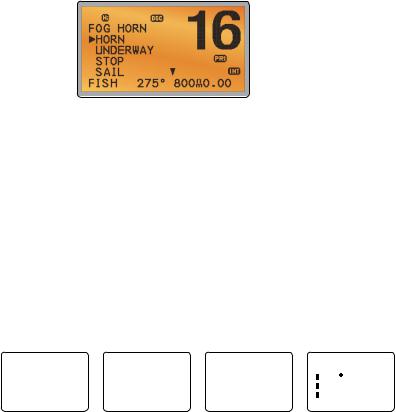
A typical operational display is shown here:
The bottom line is blank when a waypoint is not selected. This operational display shows:
•the channel that you are receiving (16) and Tx power is set to high (Hi)
•the International channel bank selected (INT) and DSC is enabled (DSC)
•the channel name tag (DISTRESS)
8 |
B&G - V50 & H50 Operation Instructions |

•your current course (128°) and speed (5.0Kt)
•your latitude (55°33.122N) and longitude (012°42.408E) and UTC time displayed in 24 hour format (14:43 - 2:43pm)
•the name of the destination waypoint (FISH), its bearing (275°), your distance in nautical miles, mile, or kilometres (depending on your choice of units) - in this case, 800nm, and the cross track error (XTE - 0.00) are shown.
All the symbols that may appear on the LCD are explained here:
Symbol
TX
BUSY
SCAN
DW
TRI
DSC
ATIS
AIS
DISTRESS 55 33.122N
012 42.408E 14:43 UTC
16
LOCAL
SKIP
A
CH1
Hi
INT
Wx
SAME
Meaning
Transmitting.
Receiver busy with an incoming signal.
Scanning for the broadcasting channel. Press PTT to stop scanning. When the broadcasting channel is found, scanning stops at that channel.
Dual watch mode. Tri watch mode.
DSC function is enabled.
ATIS is enabled for use in European inland waterways. Otherwise, blank.
AIS function is enabled.
Incoming DSC call, or blinks to notify you of any unread call log messages.
Channel name tag. Your latitude.
Your longitude.
Time (UTC). Local time has suffix LOC (for example; 12:30pm LOC). Channel selected.
Local calling is selected. Otherwise, blank for distance calling. Channel is temporarily deleted ‘skipped’ from the SCAN operation. Channel suffix, if applicable - A or B - otherwise blank.
Shows which of the 3 favorite channels, if any, are selected. CH1, CH2, CH3 - otherwise blank.
Transmission power. High (Hi) 25 W or Low (Lo) 1 W.
Selected channel bank for VHF radio operations and regulations. INT=International; USA=USA; CAN=CANADA.
Weather channel. Weather alert. US only.
Specific Area Message Encoding. US only.
B&G - V50 & H50 Operation Instructions |
9 |

D
PRI
ACK
FISH 275
800nm
0.00
NO GPS
X
Duplex operation. Otherwise, blank for Simplex operation. Priority channel is selected.
Your DSC call has been received.
Low Battery warning (activates at 10.5 V). Waypoint name and bearing.
Distance to waypoint. XTE (Cross track error). GPS data is not available. AUTO SWITCH is disabled.
1-6 Beep tones & call alerts
• |
Error |
2 short beeps |
• |
Acknowledge |
1 long beep |
• |
Alarm |
Two-tone ring |
|
|
(repeated for 2 minutes or until any key is pressed) |
• LL position call alert |
Friendly 5-tone ring sequence |
|
|
|
(press any key to cancel) |
• |
WX alert/SAME alert |
Ear-catching multi-tone sequence |
• |
ROUTINE call alert |
Friendly 5-tone ring sequence |
|
|
(press any key to cancel) |
• |
URGENCY call alert |
Two-tone ring |
|
|
(repeated for 2 minutes or until any key is pressed) |
• |
SAFETY call alert |
Two-tone ring |
|
|
(repeated for 2 minutes or until any key is pressed) |
• |
DISTRESS call alert |
Two-tone ring |
|
|
(repeated for 2 minutes or until any key is pressed) |
10 |
B&G - V50 & H50 Operation Instructions |
Section 2 - Basic operation and key functions
All possible keys and their functions are listed here. Note that some of the keys may not be available, depending on your B&G VHF radio model.
|
6 key handset mic |
V50 base station radio |
Key: |
Function: |
|
VOL / |
Volume and Power |
|
Turn clockwise to power on. Continue to turn until a comfortable volume is reached. VOL /  will also adjust the settings of an external speaker, if connected.
SQL |
Squelch or Threshold Level |
|
Sets the threshold level for the minimum receiver signal. Turn fully counterclockwise |
|
until random noise is heard, then turn slowly clockwise until the random noise |
|
disappears. Make another 1/4 turn clockwise for best reception in open sea conditions. |
|
In areas of high noise (eg. close to large cities) reception may improve if sensitivity is |
|
reduced. Either turn SQL slowly clockwise or use the LOCAL setting. See section 3-4. |
16 / 9 |
Priority channel |
|
Also on the handset mic. Press to cancel all other modes and to tune into the priority |
|
channel. Press again to return to your original channel. The default Priority Channel is |
|
CH16. |
|
For US models: To make Channel 09 the priority channel, hold down 16/9 until a |
|
beep sounds and 09 is displayed. |
DISTRESS |
Send a DSC Distress Call |
|
DSC must be active and an MMSI must be programmed. See Section 8. |
|
Lift the red cover door then press and release DISTRESS to show the DISTRESS menu. |
|
Select the category you want to transmit. Hold down DISTRESS for about 3 seconds |
|
to transmit. |
|
The DISTRESS key can also be held down continuously to transmit an “undefined” |
|
category Distress call. |
|
See Section 9 for more information about distress calls. |
B&G - V50 & H50 Operation Instructions |
11 |

PTT |
Press To Talk |
|
(Located on the handset mic). Press PTT to transmit at any time on an allowable |
|
channel. This automatically exits you from menu mode and stops scanning. You must |
|
release PTT to receive a signal. |
|
If PTT sticks, a built-in timer will automatically shut down a transmission after five |
|
minutes and sound a short error beep. |
PUSH TO SELECT Enter (ENT)
When you are in MENU mode, push the center of the Channel Select knob to enter your choice or setting. This is referred to throughout the manual as “press ENT”.
Rotary knob |
Channel select |
|
Turn to select a channel. The current channel is shown on the LCD in BIG digits and an |
|
A or B designator suffix (if applicable) in small letters below the channel number. |
|
See Appendix C for a complete listing of channel charts. |
|
Push to activate the ENT function. |
|
Alphanumeric entry |
|
You can also use the rotary knob for alphanumeric entry. Turn to step through |
|
alphanumeric characters one at a time, then push to confirm each selection. If you |
|
make an error, select the < character then push to backup. |
+ / - |
Channel select |
|
(Located on the handset mic). The current channel is shown on the screen in BIG digits |
|
with an appropriate designator suffix A or B in small letters below the channel number. |
|
Press + or - to step through the available channels one at a time, or hold down to |
|
scroll rapidly through all the available channels. |
|
See Appendix C for a complete listing of channel charts. |
|
Alphanumeric entry |
|
This key can be used for both menu selection and for alphanumeric entry. Press + or - |
|
to scroll the cursor up or down to menu options when navigating menus. |
|
When editing an item containing only numbers, press - to count through the numbers |
|
or hold down to scroll rapidly. |
|
To enter a character, press + to step through the alphabet or hold down to scroll |
|
rapidly. |
XExit
Use EXIT (X) key when navigating menus, to clear incorrect entries, to exit from a menu without saving changes, and to back up to the previous screen.
CALL/MENU DSC CALL menu
Quick press to enter the DSC CALL menu and make DSC calls. See Section 5.
12 |
B&G - V50 & H50 Operation Instructions |

|
Radio and DSC setup MENU mode |
|
Hold down for about 1 second to show the radio MENU so that you can customize |
|
your radio. See section 4. |
WX/NAV |
Weather channel |
|
For US models: In USA and Canadian waters, press to hear the most recently selected |
|
weather station. The WX symbol Wx is displayed on the LCD. Rotate the dial or + / - |
|
on the handset mic to change to a different weather channel. Press WX again to return |
|
to the most recent channel. If the weather alert mode (ALT) is ON and an alert tone of |
|
1050 Hz is broadcast from the weather station, it is picked up automatically and the |
|
alarm sounds. Press any key to hear the weather alert voice message. |
|
Note: If SAME is activated and the 6 digit County IDs you want to monitor are entered, |
|
the radio will sound the weather alarm when it detects a weather alert or weather |
|
hazard alert on the selected weather channel. |
|
For all other models: The Wx key can be programmed to a weather channel of your |
|
choice. See section 4-11 to program your favourite channel. |
|
NAV (Show waypoint) |
|
Hold down for about 1 second to enter the Navigation mode. |
|
If a waypoint is already selected, the bearing and distance to the waypoint and the |
|
cross track error are shown on the bottom line of the LCD. |
|
If you are in Navigation mode and want to scan all the VHF channels while staying in |
|
Navigation mode, just hold down SCAN. |
|
Press SCAN to quit scanning. |
3CH |
Three favourite channels |
|
Also on the handset mic. Press to toggle between your favourite channels. The CH1, |
|
CH2, or CH3 symbol appears on the LCD to show which favourite channel is selected. |
|
To scan only one of your favourite channels, press 3CH then immediately press |
|
and release SCAN. If you want to scan all three favourite channels, press 3CH then |
|
immediately press and hold SCAN. |
|
To add a favourite channel for the first time, select that channel then hold 3CH to store |
|
it in the CH1 location. Repeat the procedure to store two more favourite channels in |
|
the CH2 and CH3 locations respectively. |
|
If you try and add another favourite channel it will overwrite the existing CH3. CH1 |
|
and CH2 remain unless you delete them. |
|
To delete a favourite channel, select that channel then hold down 3CH until the CH1, |
|
CH2 or CH3 symbol disappears off the LCD. |
B&G - V50 & H50 Operation Instructions |
13 |

SCAN |
Scan (ALL SCAN & 3CH SCAN) |
|
|
There are two SCAN modes you can use to find the broadcast channel: |
|
|
• |
ALL SCAN mode scans ALL channels in sequence, and checks the priority |
|
|
channel every 2 seconds. |
|
• |
3CH SCAN mode scans the favorite channels and CH16. |
|
When a signal is received, scanning stops at that channel and BUSY appears on the |
|
|
LCD. If the signal ceases for more than 5 seconds, the scan restarts. |
|
|
Press SCAN or PTT to stop at the current channel. |
|
|
If you are in NAVIGATION mode and want to scan the DSC channels while staying in |
|
|
that mode, just hold down SCAN. |
|
|
Note: SCAN functionality is limited in some European countries and, if ATIS mode is |
|
|
enabled, the 3CH SCAN mode will be disabled and an error beep will sound. |
|
|
Note: The weather channel is also scanned if TONE ALERT or SAME is ON (US only). |
|
|
ALL SCAN mode: |
|
|
Hold down SCAN for about 3 seconds to start an ALL SCAN. ALL SCAN appears on the |
|
|
LCD. |
|
|
Press ENT to temporarily skip over (lock out) an “always busy” channel when in ALL |
|
|
SCAN mode. SKIP is shown on the top line of the LCD to designate a skipped |
|
|
channel. SKIP will disappear when the radio is powered OFF/ON. With scanning OFF |
|
|
and the SKIP channel selected, press ENT to cancel the skipped channel. |
|
|
Note: It is not possible to skip over the priority channel. |
|
|
Press SCAN to stop at the current channel. |
|
|
Press EXIT to cancel scan mode and return to normal operation. |
|
|
3CH SCAN mode |
|
|
With any of your three favorite channels selected (by pressing the 3CH key) hold down |
|
|
SCAN to start all 3CH scanning. Press SCAN again to stop at the broadcast channel, |
|
|
or press EXIT to quit 3CH SCAN and return automatically to the previous broadcast |
|
|
channel. |
|
AIS / IC |
AIS (Automatic Identification System) |
|
|
Quick press to enter the AIS menu. |
|
|
See section 6 for AIS setup or Section 9 for AIS functionality. |
|
14 |
B&G - V50 & H50 Operation Instructions |
IC (FOG HORN mode)
Hold down for about 1 second to enter HAILER mode. Select FOG HORN. The FOG HORN will sound certain international standard fog horn tones through the hailer speaker depending on the mode selected.
See section 11 for HAILER functionality.
IC (PA HAILER mode)
Hold down for about 1 second to enter HAILER mode. Select PA (Public Address). The PA allows you to make an announcement at high volume to people or vessels using the V50 hand mic.
See section 11 for HAILER functionality.
GO / MOB |
GO (Reset the Cross Track Error) |
|
||
|
Note: A valid GPS signal must be received to see this selection. |
|||
|
Press GO if you are navigating to a waypoint and want to reset the cross track error. |
|||
|
This is a very useful single keystroke feature to use if you wander a little off-course but |
|||
|
want to continue to your active waypoint. |
|
||
|
The bearing and distance to the waypoint and any cross track error are shown on the |
|||
|
bottom line of the LCD. |
|
|
|
|
MOB (Man Over Board) |
|
|
|
|
Hold down MOB until the radio automatically enters Navigation mode, saves your cur- |
|||
|
rent latitude and longitude as the MOB waypoint and immediately sets this position |
|||
|
as the destination waypoint. |
|
|
|
|
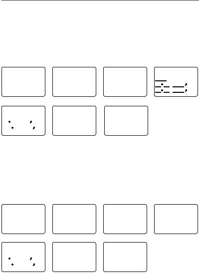
You will see the following sequence of LCDs: |
|
||
HOLD 3 SEC |
HOLD 2 SEC |
HOLD 1 SEC |
MOB |
|
FOR MOB |
FOR MOB |
FOR MOB |
B 010 |
|
RELEASE TO |
RELEASE TO |
RELEASE TO |
||
D 0.01 |
||||
SAVE |
SAVE |
SAVE |
||
X 0.00 |
||||
|
|
|
||
The bearing and distance to the Man Overboard position, and any cross track error (XTE), are shown on the bottom line of the LCD.
To cancel MOB, select another waypoint.
B&G - V50 & H50 Operation Instructions |
15 |

MOB (Temporary waypoint)
To mark your current position as a temporary waypoint, hold down MOB and release the key before the 3 second countdown ends.
You will see the following sequence of LCDs:
HOLD 3 SEC |
HOLD 2 SEC |
HOLD 1 SEC |
FOR MOB |
FOR MOB |
FOR MOB |
RELEASE TO |
RELEASE TO |
RELEASE TO |
SAVE |
SAVE |
SAVE |
|
The new temporary waypoint is shown in your waypoints list. Hold down MENU, press |
|
ENT, then press ENT again to display the waypoints list (TEMP1, WP001, WP002). |
|
You cannot store more than three temporary waypoints. If you store another tempo- |
|
rary waypoint, TEMP1 is overwritten with the new information. |
H/L |
Transmission power |
|
(Located on the handset mic). High (HI) 25 W or Low (LO) 1 W. Press to toggle between |
|
high or low transmission power for the entire channel bank. The HI or LO selection is |
|
shown on the LCD. |
|
Some channels allow only low power transmissions. Error beeps will sound if the |
|
power transmission setting is incorrect. |
|
Some channels allow only low power transmissions initially, but can be changed to |
|
high power by holding down H/L and PTT at the same time. |
|
See Appendix C for a complete listing of channel charts. |
Softkeys: |
This radio uses virtual softkeys during certain functions. A softkey is defined by a name |
|
that appears at the bottom of the LCD that positioned immediately above an actual |
|
key on the radio. A softkey provides you with the additional function or choice when |
|
the softkey appears during certain functions: |
ACK |
Able key (WX/NAV key) |
|
Press to ACK (acknowledge) a DSC call. |
ACCEPT |
Accept key (AIS/IC key) |
|
Press to ACCEPT a channel request. The radio will immediately change to the |
|
requested channel. |
NEW-CH |
New channel request key (AIS/IC key) |
|
Press to request a new channel. |
PAUSE |
PAUSE key (WX/NAV key) |
|
Press to pause a call when in repeat mode. |
RESEND |
Resend key (AIS/IC key) |
|
Press to resend the DSC call. |
SILENC |
Silence key (AIS/IC key) |
|
Provided as an option to silence an audible alarm. |
16 |
B&G - V50 & H50 Operation Instructions |

Section 3 - Radio MENU SELECT options
Hold down CALL MENU for about 1 second to access any of the following radio MENU SELECT options. Menu options shown inside the gray boxes are explained in this section.
WAYPOINT |
|
|
Section 3-1 |
BACKLIGHT |
|
|
Section 3-2 |
BUDDY LIST |
|
|
Section 3-3 |
LOCAL/DIST |
|
|
Section 3-4 |
CONTRAST |
|
|
Section 3-5 |
GPS/DATA |
MANUAL |
|
Section 3-6-1 |
|
SETTING |
TIME OFFSET |
Section 3-6-2 |
|
|
TIME FORMAT |
Section 3-6-3 |
|
|
TIME DISPLY |
Section 3-6-4 |
|
|
LL DISPLY |
Section 3-6-5 |
|
|
COG/SOG |
Section 3-6-6 |
|
|
GPS ALERT |
Section 3-6-7 |
RADIO SETUP |
UIC (US and AUS only) |
|
Section 4-1 |
|
CH NAME |
|
Section 4-2 |
|
RING VOLUME |
|
Section 4-3 |
|
KEY BEEP |
|
Section 4-4 |
|
UNITS |
|
Section 4-5 |
|
INT SPEAKER |
|
Section 4-6 |
|
WATCH MODE (US only) |
|
Section 4-7 |
|
WX ALERT (US only) |
TONE ALERT |
Section 4-8-1 |
|
|
SAME ALERT |
Section 4-8-2 |
|
|
SAME CODE |
Section 4-8-5 |
|
COM PORT |
|
Section 4-9 |
|
GPS SOURCE |
|
Section 4-10 |
|
FAV CH SETU (EU and AUS only) |
|
Section 4-11 |
DSC SETUP |
USER MMSI |
|
Section 5-1 |
|
GROUP SETUP |
|
Section 5-2 |
|
ATIS MMSI (EU only) |
|
Section 5-3 |
|
ATIS SELECT (EU only) |
|
Section 5-4 |
|
INDIV REPLY |
|
Section 5-5 |
|
DSC FUNC |
|
Section 5-6 |
|
LL REPLY |
|
Section 5-7 |
|
AUTO SWITC |
|
Section 5-8 |
|
TEST REPLY |
|
Section 5-9 |
|
TIMEOUT |
|
Section 5-10 |
AIS SETUP |
AIS FUNC |
|
Section 6-1 |
|
AIS DISPLAY |
|
Section 6-2 |
|
BAUD RATE |
|
Section 6-3 |
|
GPS REDIR |
|
Section 6-4 |
|
CPA ALARM |
|
Section 6-5 |
|
CPA |
|
Section 6-6 |
|
TCPA |
|
Section 6-7 |
GPS SIM |
|
|
Section 3-7 |
HS SETTING |
SUBSCRIBE |
|
Section 7-1 |
|
REGISTERED HS |
|
Section 7-2 |
RESET |
|
|
Section 3-8 |
B&G - V50 & H50 Operation Instructions |
17 |
3-1 Manage your waypoints list (WAYPOINT)
•You can store a maximum of 200 waypoints with their LL positions. When your waypoint list is full, you cannot make a new entry until you have deleted an existing entry
•Each waypoint name can have a maximum of 6 alphanumeric characters
•Waypoints are stored in order of entry, with the most recent entry shown first
•The waypoints are displayed in columns of 6 with a box. Rotate the Channel Select knob to scroll through the columns to easily locate your desired waypoint. Then press ENT and use the Channel Select knob to select a waypoint within the column.
3-1-1 Add a new waypoint
MENU SELECT |
WAYPOINT |
WP LIST |
ENTER WP |
|
||
►WAYPOINT |
►WP LIST |
NEW WP |
|
R01W04 |
|
|
BACKLIGHT |
NEAREST WP |
R01W01 |
|
R14W05 |
. |
N |
BUDDY LIST |
TEMP |
R01W02 |
|
R14W06 |
||
|
|
|
||||
LOCAL/DIST▼ |
|
R14W03 |
|
|
. |
W |
|
|
|
|
|
||
ENTER WP |
SAVE |
WP LIST |
|
|
||
R01W07 |
►YES |
NEW WP |
R01W04 |
|
|
|
17 32.233 N |
R01W01 |
R14W05 |
|
|
||
160 45.651 E |
NO |
R01W02 |
R14W06 |
|
|
|
|
R01W03 |
R14W07 |
|
|
||
|
|
|
|
|||
|
|
|
|
|
|
|
1.Select WAYPOINT then WP LIST.
2.Your waypoint list is displayed. Press ENT.
3.NEW WP starts to flash. Press ENT to add a new waypoint.
4.Enter a waypoint name (maximum 6 characters), then the latitude, then the longitude.
5.Press ENT when all the information is correct then select YES.
The new waypoint is saved and your waypoint list is displayed again.
3-1-2 Edit or delete a waypoint
MENU SELECT |
WAYPOINT |
WP LIST |
R14W05 |
|
►WAYPOINT |
►WP LIST |
NEW WP |
R01W04 |
►WP EDIT |
BACKLIGHT |
NEAREST WP |
R01W01 |
R14W05 |
DELETE |
BUDDY LIST |
TEMP |
R01W02 |
R14W06 |
GO |
LOCAL/DIST▼ |
|
R01W03 |
R14W07 |
TX WPT DATA |
WP EDIT |
SAVE |
WP LIST |
|
|
R14END |
R14END |
NEW WP |
R01W04 |
|
17 32.233 N |
►YES |
R01W01 |
R14END |
|
160 45.651 E |
NO |
R01W02 |
R14W06 |
|
|
R01W03 |
R14W07 |
|
|
|
|
|
||
|
|
|
|
|
1.Select WAYPOINT then WP LIST.
18 |
B&G - V50 & H50 Operation Instructions |

Note: A valid GPS signal must be received to see parts of this selection.
2.Your waypoint list is displayed. Press ENT.
3.NEW WP starts to flash. Scroll down to the incorrect entry. The selected waypoint flashes. Press ENT again.
4.To delete the waypoint, select DELETE then YES. The waypoint is deleted immediately and the waypoint list is refreshed and displayed again.
5.To edit the waypoint, select WP EDIT. The cursor is at the first character of the name. Edit the waypoint name or to edit only the latitude or longitude, press ENT repeatedly until the cursor moves to the required line.
6.When you are finished, press ENT (repeatedly if necessary) until an updated page appears.
7.Press ENT to store the changes. The waypoint list is displayed again. If more changes are required, repeat steps 2 through 6. Otherwise, press EXIT to cancel any edits.
3-1-3 Go to a new waypoint
MENU SELECT |
WAYPOINT |
WP LIST |
R01W01 |
|
►WAYPOINT |
►WP LIST |
NEW WP |
R01W04 |
WP EDIT |
BACKLIGHT |
NEAREST WP |
R01W01 |
R14END |
DELETE |
BUDDY LIST |
TEMP |
R01W02 |
R14W06 |
►GO |
LOCAL/DIST▼ |
|
R01W03 |
R14W07 |
TX WPT DATA |
1.Select WAYPOINT then WP LIST.
2.Your waypoint list is displayed. Press ENT.
3.NEW WP starts to flash. Scroll down to the waypoint you want to go to. The selected waypoint flashes. Press ENT again.
4.Select GO.
5.Select Yes. The waypoint is set immediately as the destination waypoint.
Tip: If you are in the NAV big number screen, just turn the Channel Select knob to immediately access the Waypoint List. Select the new waypoint and press ENT.
3-1-4 Go to nearest waypoint (NEAREST WP)
Note: A valid GPS signal must be received to see this selection.
MENU SELECT |
WAYPOINT |
NEAREST |
WP |
►WAYPOINT |
WP LIST |
►R01W04 001 |
|
BACKLIGHT |
►NEAREST WP |
|
98 |
BUDDY LIST |
TEMP |
R01W01 |
003 |
LOCAL/DIST▼ |
|
|
136 |
1.Select WAYPOINT then NEAREST WP.
2.Press ENT to display the nearest waypoint with distance and bearing from your current position.
Other waypoints are listed in increasing distance from your current position.
B&G - V50 & H50 Operation Instructions |
19 |

3.Press ENT to set the nearest waypoint as the active waypoint OR move the cursor to another waypoint and then press ENT.
The chosen waypoint is shown on the bottom line of the LCD.
3-1-5 Go to temporary waypoint
MENU SELECT |
WAYPOINT |
TEMP |
TEMP1 |
►WAYPOINT |
WP LIST |
►TEMP1 |
►GO |
BACKLIGHT |
NEAREST WP |
TEMP2 |
TEMP EDIT |
BUDDY LIST |
►TEMP |
|
DELETE |
LOCAL/DIST▼ |
|
|
|
1.Select WAYPOINT then TEMP.
2.Your temporary waypoint list is displayed. There are 3 choices for quick access.
3.Select the temporary waypoint to go to. Press ENT.
4.Press ENT to set the temporary waypoint as the destination waypoint. It is immediately shown on the bottom line of the LCD.
Tip: Hold down MOB and release before the 3 second countdown completes. Your current LL position is stored in TEMP1 to TEMP3 in the waypoint list.
If the list is full, a message appears. See following section to delete a TEMP WP.
TEMP IS
FULL
3-1-6 Edit or delete a temporary waypoint
MENU SELECT |
WAYPOINT |
TEMP |
TEMP2 |
►WAYPOINT |
WP LIST |
TEMP1 |
GO |
BACKLIGHT |
NEAREST WP |
►TEMP2 |
TEMP EDIT |
BUDDY LIST |
►TEMP |
|
►DELETE |
LOCAL/DIST▼ |
|
|
|
DELETE |
WAYPOINT |
|
|
►YES |
WP LIST |
|
|
NO |
NEAREST WP |
|
|
|
►TEMP |
|
|
1.Select WAYPOINT then TEMP. Your temporary waypoint list is displayed.
2.Select the temporary waypoint to edit then select TEMP EDIT.
Note: To delete the temporary waypoint, select DELETE then YES. The temporary waypoint is deleted immediately and the temporary waypoint list is displayed again.
20 |
B&G - V50 & H50 Operation Instructions |
3.The waypoint details are displayed. The cursor is at the first character of the name.
4.Edit the temporary waypoint name or to edit only the latitude or longitude, press ENT repeatedly until the cursor moves to the required line.
5.When you are finished, press ENT (repeatedly if necessary) until a new LCD appears.
6.Press ENT to store the changes. The waypoint list is displayed again. If more changes are required, repeat steps 2 through 6. Otherwise, press EXIT.
3-1-7 Send waypoint data to a chartplotter
You can send waypoint data over NMEA 2000 to a compatible chartplotter.
MENU SELECT |
WAYPOINT |
WP LIST |
TEMP2 |
►WAYPOINT |
►WP LIST |
NEW WP |
WP EDIT |
BACKLIGHT |
NEAREST WP |
MOB |
DELETE |
BUDDY LIST |
TEMP |
TEMP1 |
GO |
LOCAL/DIST▼ |
|
TEMP2 |
►TX WP DATA |
1.Select WAYPOINT then WP LIST. Your waypoint list is displayed. Press ENT. NEW WP starts to flash.
2.Scroll down to the waypoint whose data you want to send to the chartplotter then press ENT. In the example scroll to TEMP2 then press ENT.
3.Scroll down and select TX WPT DATA and press ENT to send the data.
3-2 Set the backlighting level (BACKLIGHT)
There are 8 levels of backlight. Level 8 is the brightest, Level 0 is OFF. The backlight function affects the base station (LCD and Keypad) and the microphone keypad backlight.
MENU SELECT |
BACKLIGHT |
|
WAYPOINT |
|
|
►BACKLIGHT |
LO |
HI |
BUDDY LIST |
PRESS ENT |
|
LOCAL/DIST▼ |
|
|
1.Select BACKLIGHT.
2.Select a comfortable level using the Channel Select knob or + or – on the microphone to change the setting.
3.Press ENT to enable the setting and return to the menu.
Note: The DISTRESS key backlight cannot be switched off.
Note: If the backlight setting is set to level 0 (OFF), the backlight will automatically turn ON at level 1 if the radio detects any DSC activity, or any buttons are pressed. The backlight will return to level 0 (OFF) after 10 seconds of inactivity.
B&G - V50 & H50 Operation Instructions |
21 |

3-3 Maintain your buddy list (BUDDY LIST)
Use the buddy list to store the names and associated MMSIs of 20 favorite people. Names are stored in the order of entry, with the most recent entry shown first.
The following sections show how to add, edit and delete entries on your BUDDY LIST.
Section 7-3 explains how to call a buddy.
3-3-1 Add an entry
You can enter a maximum of 20 buddy names. When your BUDDY LIST is full, you cannot make a new entry until you have deleted an existing entry.
Each buddy name can have a maximum of 11 alphanumeric characters.
MENU SELECT |
BUDDY LIST |
ENTER NAME |
ENTER NAME |
WAYPOINT |
►MANUAL NEW |
|
STARFISH |
BACKLIGHT |
SEA ROSE |
ENTER MMSI |
ENTER MMSI |
►BUDDY LIST |
MERMAID IV |
|
|
|
|
||
LOCAL/DIST▼ |
|
|
|
ENTER NAME |
STARFISH2 |
BUDDY LIST |
|
STARFISH |
123456789 |
►MANUAL NEW |
|
ENTER MMSI |
►STORE |
STARFISH |
|
123456789 |
SEA ROSE |
|
|
CANCEL |
|
||
|
|
MERMAID IV |
|
1.Select BUDDY LIST. The cursor is at MANUAL NEW. Press ENT.
2.Enter the buddy name, one character at a time (this may be alphanumeric) then press ENT repeatedly until the cursor moves to the MMSI entry line.
3.Enter the MMSI associated with that buddy name (this must be numeric) then press ENT.
4.The new buddy name and MMSI are displayed. Press ENT to store the new entry, which is displayed at the top of your buddy list.
Note: When the BUDDY LIST is full (20 entries), you can make a new entry and the buddy at the end of the list is automatically erased.
22 |
B&G - V50 & H50 Operation Instructions |

3-3-2 Edit or delete an entry
MENU SELECT |
BUDDY LIST |
BUDDY LIST |
SEA ROSE |
WAYPOINT |
►MANUAL NEW |
MANUAL NEW |
►EDIT |
BACKLIGHT |
SEA ROSE |
►SEA ROSE |
DELETE |
►BUDDY LIST |
MERMAID IV |
MERMAID IV |
|
LOCAL/DIST▼ |
|
|
|
EDIT NAME |
EDIT NAME |
SEA ROSE 2 |
|
SEA ROSE |
SEA ROSE 2 |
122256798 |
|
EDIT MMSI |
EDIT MMSI |
►STORE |
|
123456789 |
122256798 |
CANCEL |
|
1.Select BUDDY LIST. The cursor is at MANUAL NEW.
2.Scroll down to the incorrect entry and press ENT.
3.To delete the buddy, select DELETE then YES. The buddy is deleted immediately and the buddy list is displayed again.
4.To edit the buddy, select EDIT. The cursor is at the first character of the name. Edit the buddy name or to edit only the MMSI, press ENT repeatedly until the cursor moves to the MMSI line.
5.When you are finished, press ENT (repeatedly if necessary) until an updated screen appears.
6.Press ENT to store the changes. The buddy list is displayed again. If more changes are required, repeat steps 2 through 6. Otherwise, press EXIT to ESC.
3-4 Local or distance sensitivity (LOCAL/DIST)
Use LOCAL/DIST to improve the sensitivity of the receiver either locally (LOCAL) or over distances (DIST). LOCAL is not recommended for use in open sea conditions. It is designed for use in areas of high radio noise; for example, close to cities.
See also SQL (Squelch Control) in section 2.
3-4-1 Set distance sensitivity
MENU SELECT |
▲ |
SENSITIVITY |
BACKLIGHT |
►DISTANT |
|
BUDDY LIST |
|
LOCAL |
►LOCAL/DIST |
▼ |
|
CONTRAST |
|
1.Select LOCAL/DIST then select DISTANT.
2.Press ENT to activate the DIST setting. This disables local sensitivity and the menu is displayed again.
B&G - V50 & H50 Operation Instructions |
23 |
3-4-2 Set local sensitivity
MENU SELECT |
▲ |
SENSITIVITY |
BACKLIGHT |
DISTANT |
|
BUDDY LIST |
|
►LOCAL |
►LOCAL/DIST |
▼ |
|
CONTRAST |
|
1.Select LOCAL/DIST then scroll to LOCAL.
2.Press ENT to activate the LOCAL setting. This disables distance sensitivity and the menu is displayed again.
LOCAL is displayed on the LCD as a reminder that sensitivity is reduced.
3-5 Set the contrast level (CONTRAST)
There are 8 levels of contrast.
MENU SELECT |
|
CONTRAST |
|
BUDDY LIST▲ |
|
|
|
LOCAL/DIST |
|
LO |
HI |
►CONTRAST |
▼ |
PRESS ENT |
|
GPS/DATA |
|
|
|
1.Select CONTRAST.
2.Select a comfortable contrast level using the Channel Select knob or + or – on the microphone to change the setting.
3.Press ENT to enable the setting and return to the menu.
3-6 GPS data and time (GPS/DATA)
If the boat has an operational GPS navigation receiver and is connected by NMEA port, the VHF radio automatically detects and updates the vessel position and the local time.
However, if the GPS navigation receiver is disconnected or absent, you can specify the vessel position and the local time manually, using the GPS/DATA option.
This information is important because it will be used if a DSC distress call is transmitted.
•If GPS data is NOT available for some reason, the NO GPS alert will sound for 5 seconds (or until you press any key) and the radio requests you to enter the position data manually
•This request is repeated every 4 hours if you do not enter the position data manually. After you have entered the position data manually, you must update it within 23.5 hours otherwise the NO GPS alert sequence repeats
•The NO GPS warning will be shown whenever GPS data is not available from an operational GPS navigation receiver.
24 |
B&G - V50 & H50 Operation Instructions |

3-6-1 Manually enter position and UTC time (MANUAL)
Note: this function is available only if an operational GPS receiver is not connected.
MENU SELECT |
GPS/DATA |
MANUAL LL |
|
14:38 UTC |
|
|
LOCAL/DIST |
►MANUAL |
. |
N |
M17 |
32.233 |
S |
CONTRAST |
SETTING |
. |
W |
160 |
45.651 |
E |
►GPS/DATA |
|
|||||
|
MAN --:--UTC |
|
|
|
||
RADIO SETU |
|
|
|
|
|
|
1.Select GPS/DATA then MANUAL.
2.Enter the latitude, then the longitude, then the UTC.
3.Press ENT when all the information is correct.
The vessel’s latitude and longitude are shown on the screen, with the UTC time. The prefix M indicates a manual entry. The manual entries are cancelled if a real GPS position is received.
Note: a warning will be displayed after 4 hours to remind you that the current position information is manually entered.
3-6-2 Local time (TIME OFFSET)
If your position and time data are being updated through a GPS navigation receiver, you can enter the time difference between UTC and local time and display your local time on the LCD.
MENU SELECT |
GPS/DATA |
SETTING |
TIME OFFSET |
LOCAL/DIST▲ |
MANUAL |
►TIME OFFSET |
+00.00 |
CONTRAST |
►SETTING |
TIME FORMAT |
|
►GPS/DATA |
|
TIME DISPLY |
04:43 UTC |
RADIO SETU▼ |
|
LL DISPLY ▼ |
|
TIME OFFSET |
07:50AM LOC |
|
|
+03.00 |
17 36.233 N |
|
|
|
|
|
|
07:43 LOC |
161 05.651 E |
|
|
|
|
|
1.Work out the time difference between UTC and your local time (from the following graphic).
2.Select GPS/DATA then SETTING.
3.Select TIME OFFSET to enter the difference between UTC and local time. Use the Channel Select knob or + or – to change the time. Half hour increments can be used with a maximum offset of ±13 hours.
4.Press ENT when the local time is correct.
LOC is displayed after the time on the LCD as a reminder that local time is selected.
B&G - V50 & H50 Operation Instructions |
25 |

LM Y X W V U T S R Q P O N Z A B C D E F G H I K L M Y |
|
||||||||||||||||||||||||
|
|
|
|
|
|
S |
Q |
§ |
Z |
A |
|
|
|
|
|
|
|
|
|
|
L |
|
|
|
|
|
|
|
|
|
|
|
|
|
|
|
|
|
|
|
|
|
|
|
|
|
|
|
|||
|
|
|
|
|
|
T |
R |
N |
|
|
|
|
|
|
|
|
|
|
|
|
|
|
|
|
|
|
|
|
|
|
|
|
|
|
|
|
|
|
|
|
|
|
|
|
|
|
|
|
|
||
M |
|
|
|
V |
|
S |
|
|
Z |
|
|
|
|
|
|
H |
|
K |
|
L |
M |
|
|
||
|
|
|
|
|
P |
|
A |
B |
|
|
|
|
|
|
|
|
|||||||||
|
|
|
|
|
|
|
|
|
F |
|
|
|
|
|
|
|
|
|
|
|
|
||||
|
|
|
|
|
|
|
|
|
Z |
|
B |
D |
G |
|
|
I |
|
|
|
|
|
|
|
|
|
|
W |
|
|
U |
T |
Q |
|
C |
|
|
|
|
|
|
|
|
|
|
|
||||||
|
|
|
|
C |
|
|
|
|
|
|
|
|
|
|
|
||||||||||
|
|
|
|
|
|
|
|
|
|
|
F |
|
|
|
|
|
|
|
|
|
|
|
|||
|
Line Date International |
|
|
|
|
R |
P* |
|
A |
B |
|
E |
|
|
|
|
|
|
|
M |
|
|
|
||
|
|
|
|
|
|
|
|
|
|
|
|
|
|
|
|
|
|
|
|
|
|
|
|||
|
|
|
|
|
S |
|
|
|
|
|
|
|
|
|
|
|
|
|
|
|
|
|
|
||
|
|
|
|
U |
R |
N |
Z |
|
B |
|
E |
|
|
|
H |
|
I |
|
I |
|
|
|
|
||
|
X |
|
|
|
T |
|
|
|
|
|
C* D* |
|
|
|
|
|
|
|
|
|
|||||
|
|
|
|
|
|
|
|
|
|
|
|
† |
|
|
|
I |
|
|
|
|
X |
|
|||
|
|
W |
|
|
|
R |
|
|
|
B |
C |
E |
|
E |
|
|
H |
|
|
|
|
LineInternationalDate |
MAPWORLD |
||
|
|
|
|
|
|
|
|
|
D |
E* |
F |
F* |
|
|
|
|
|
||||||||
|
|
|
|
|
R |
Q |
N |
Z |
A |
|
|
|
|
|
|
|
|
||||||||
|
|
|
|
|
|
|
|
|
|
|
|
|
|
|
|||||||||||
|
|
|
|
|
S |
|
|
|
|
C |
|
C |
|
|
|
G |
|
|
|
K |
M |
|
|||
|
|
|
|
|
R Q* |
|
|
|
|
|
E* |
|
|
|
|
|
|||||||||
M |
|
M† |
|
|
|
|
|
Z |
|
|
E |
H |
H |
|
|
|
|
M |
|||||||
|
|
M* |
|
V* |
S |
|
|
|
A |
B |
C |
D |
|
|
|
G |
|
I |
|
K |
|
|
|
OF |
|
|
|
|
|
|
Q |
O |
|
|
F |
|
|
G |
|
|
L |
|
|
||||||||
|
|
|
|
|
|
|
|
|
|
|
|
|
|
|
I K |
|
|
||||||||
L |
M |
M* |
W |
|
|
|
P |
Z |
A |
|
C |
|
|
|
|
|
H |
|
|
|
|
L |
M |
TIME |
|
|
XW |
|
|
|
|
|
|
|
|
F* |
|
|
|
|
|
|
|||||||||
|
|
M* |
|
|
|
|
O |
|
|
C |
D |
|
|
|
|
|
L |
M* |
|||||||
|
|
|
W |
U |
|
|
|
|
|
|
|
|
|
|
H |
I* |
|
|
|
||||||
|
|
|
|
S |
|
|
|
|
|
|
|
|
|
|
|
|
|
|
|
ZONES |
|||||
|
|
|
|
|
Q |
|
|
|
B |
|
|
|
|
|
|
K |
|
* |
|
||||||
|
M |
|
|
|
|
|
|
|
|
|
|
|
|
|
|
|
|
|
|
||||||
|
|
|
|
|
P |
|
Z |
|
|
|
|
|
|
|
|
|
|
|
* |
L |
M |
||||
|
|
|
|
|
|
|
|
|
|
|
|
|
|
|
|
|
|
|
|
K |
|
||||
|
|
M |
|
|
|
|
|
|
|
|
|
|
|
|
|
|
|
|
|
|
K |
|
|
M |
|
|
|
STANDARD TIME ZONES |
|
P |
|
|
|
|
|
|
|
|
|
|
|
|
|
M |
|
|
|||||
|
|
|
|
Standard Time |
= Universal Time – value from table |
|
|
|
|
|
|
|
|||||||||||||
|
|
|
O |
|
|
|
|
|
|
|
|
||||||||||||||
|
|
|
Corrected to March 2013 |
|
|
Universal Time |
= Standard Time + value from table |
|
|
|
|
|
|
|
|
||||||||||
|
Zone boundaries are approximate |
|
|
|
h m |
h m |
|
h m |
|
h m |
|
h m |
|
h m |
|
h m |
|
|
|
|
Daylight Saving Time (Summer Time), |
|
Z |
0 |
D* – 4 30 |
G |
– 7 |
L |
–11 |
N |
+ 1 |
Q* + 4 30 |
V |
+ 9 |
|
|
|||
usually one hour in advance of Standard |
|
A |
– 1 |
E – 5 |
H |
– 8 |
L* |
–11 30 |
O |
+ 2 |
R |
+ 5 |
V* |
+ 9 30 |
|
|
|||
|
B |
– 2 |
E* – 5 30 |
I |
– 9 |
M |
–12 |
P |
+ 3 |
S |
+ 6 |
W |
+10 |
|
|
||||
|
Time, is kept in some places |
|
|
|
|
||||||||||||||
|
|
|
C |
– 3 |
E† – 5 45 |
I* |
– 9 30 |
M |
–12 45 |
P* + 3 30 |
T |
+ 7 |
X |
+11 |
|
|
|||
|
|
|
|
|
§ |
|
|||||||||||||
|
Map outline © Mountain High Maps |
|
C* – 3 30 |
F – 6 |
K |
–10 |
M* –13 |
Q + 4 |
U |
+ 8 |
Y |
+12 |
|
||||||
Compiled by HM Nautical Almanac Office |
P |
D |
– 4 |
F* – 6 30 |
K* –10 30 |
M† –14 |
§ No Standard Time legally adopted |
|
|
||||||||||
180° |
150°W |
120°W |
90°W |
60°W |
30°W |
0° |
|
30°E |
|
60°E |
|
90°E |
120°E |
150°E |
180° |
||||
3-6-3 Time format options (TIME FORMAT)
Time can be shown in 12 or 24 hour format.
MENU SELECT |
GPS/DATA |
SETTING |
TIME FORMAT |
LOCAL/DIST▲ |
MANUAL |
TIME OFFSET |
►12 Hr |
CONTRAST |
►SETTING |
►TIME FORMAT |
24 Hr |
►GPS/DATA |
|
TIME DISPLY |
06:56PM LOC |
RADIO SETU▼ |
|
LL DISPLY ▼ |
|
1.Select GPS/DATA then SETTING.
2.Select TIME FORMAT.
3.Select 12 or 24 hr as desired. In this example, 12 hour format has been selected and so the LCD shows the AM or PM suffix.
3-6-4 Time display options (TIME DISPLY)
If your vessel position and time data are being updated through a GPS navigation receiver, you can show or hide the time on the LCD.
26 |
B&G - V50 & H50 Operation Instructions |

MENU SELECT |
GPS/DATA |
SETTING |
TIME DISPLY |
LOCAL/DIST▲ |
MANUAL |
TIME OFFSET |
►ON |
CONTRAST |
►SETTING |
TIME FORMAT |
OFF |
►GPS/DATA |
|
►TIME DISPLY |
|
RADIO SETU▼ |
|
LL DISPLY ▼ |
|
1.Select GPS/DATA then SETTING.
2.Select TIME DISPLY.
3.Select ON (on) or OFF (off ) as desired. In this example, OFF has been selected and the LCD no longer shows the time.
3-6-5 Position display options (LL DISPLY)
If your vessel position and time data are being updated through a GPS navigation receiver, you can show or hide your vessel position on the LCD.
MENU SELECT |
GPS/DATA |
SETTING |
LL DISPLY |
LOCAL/DIST▲ |
MANUAL |
TIME FORMAT |
►ON |
CONTRAST |
►SETTING |
TIME DISPLY |
OFF |
►GPS/DATA |
|
►LL DISPLY |
|
RADIO SETU▼ |
|
COG/SOG |
|
1.Select GPS/DATA then SETTING.
2.Select LL DISPLY.
3.Select ON (on) or OFF (off ) as desired. In this example, OFF has been selected and the LCD no longer shows the vessel position.
3-6-6 Course & speed display options (COG/SOG)
If your vessel position and time data are being updated through a GPS navigation receiver, you can show or hide your course over ground (COG) and speed over ground (SOG) data on
the LCD.
MENU SELECT |
GPS/DATA |
SETTING |
COG/SOG |
LOCAL/DIST▲ |
MANUAL |
TIME DISPL▲ |
ON |
CONTRAST |
►SETTING |
LL DISPLY |
►OFF |
►GPS/DATA |
|
►COG/SOG |
|
RADIO SETU▼ |
|
GPS ALERT |
|
1.Select GPS/DATA then SETTING.
2.Select COG/SOG.
3.Select ON (on) or OFF (off ) as desired. In this example, ON has been selected and so the LCD shows the bearing and speed.
B&G - V50 & H50 Operation Instructions |
27 |

3-6-7 GPS alert (GPS ALERT)
If the GPS Alert is ON and the GPS navigation receiver is disconnected, the alarm sounds.
Note: The default setting is ON for the V50 EU and OFF for the V50 US.
MENU SELECT |
GPS/DATA |
SETTING |
GPS ALERT |
LOCAL/DIST▲ |
MANUAL |
TIME DISPL▲ |
►ON |
CONTRAST |
►SETTING |
LL DISPLY |
OFF |
►GPS/DATA |
|
COG/SOG |
|
RADIO SETU▼ |
|
►GPS ALERT |
|
1.Select GPS/DATA then SETTING.
2.Select GPS ALERT.
3.Select ON (on) or OFF (off ) as desired.
3-7 GPS simulator (GPS SIM)
The GPS simulator is set to OFF whenever the radio is turned ON or whenever real GPS data is available through the COM port. (The GPS simulator will not operate if a GPS signal is received).
However, if you want to test it, turn it ON. Note that DSC transmissions will be blocked while the GPS simulator is ON.
MENU SELECT |
GPS SIM |
|
RADIO SETU▲ |
ON |
|
DSC SETUP |
|
►OFF |
AIS SETUP |
▼ |
|
►GPS SIM |
|
|
1.Select GPS SIM.
2.Select ON (on) or OFF (off ) as desired.
3-8 Reset to factory defaults (RESET)
Use this to return every setting to the factory defaults except all MMSI settings and the entries in your buddy list.
MENU |
SELECT |
▲ |
RESET RADIO |
DSC |
SETUP |
ARE YOU SURE |
|
AIS |
SETUP |
|
YES |
GPS SIM |
|
►NO |
|
►RESET |
|
|
|
1.Select RESET. The radio asks for confirmation.
2.Select YES then press ENT to confirm and reset the radio. The menu is displayed again.
28 |
B&G - V50 & H50 Operation Instructions |
Loading...