


Bertazzoni PM363I0XLP Installation Manual

INSTALLATION,USE & CARE MANUAL
(French version page 12)
DIMENSIONS: 35
Models PMMN...D7X (2 or 5)D PM363I0X
1/16’’ (890 mm)(W) x 201/2’’ (520 mm)(D)

IMPORTANT: SAVE FOR LOCAL ELECTRICAL INSPECTOR’S USE.
READ AND SAVE THESE INSTRUCTIONS FOR FUTURE REFERENCE.
OBSERVE ALL GOVERNING CODES AND ORDINANCES.
WARNING: If the information in this manual is not followed exactly, a fire or
explosion may result causing property damage, personal injury or death.
Do not store or use gasoline or other flammable vapors and liquid in the vicinity of
this or any other appliance.
WHAT TO DO IF YOU SMELL GAS
- Do not try to light any appliance.
- Do not touch any electrical switch.
- Do not use any phone in your building.
- Immediately call your gas supplier from a neighbor’s phone. Follow
the gas supplier’s instructions.
- If you cannot reach your gas suppliers, call the fire department.
Installation and service must be performed by a qualified installer, service agency
or the gas supplier.
Read this instruction booklet before installing and using the appliance.
The manufacturer will not be responsible for any damage to property or to persons caused by
incorrect installation or improper use of the appliance.
The manufacturer reserves the right to make changes to its products when considered necessary and useful,
without affecting the essential safety and operating characteristics.
This appliance has been designed for non-professional, domestic use only.
2

WARRANTY AND SERVICE
All Bertazzoni products are covered by a 2 years parts and labor warranty.
Service on all Bertazzoni products shall be carried out by factory-trained professionals only.
For warranty service please contact Customer Service at the numbers indicated below.
CUSTOMER SERVICE
English/Spanish hotline (866) 905-0010
French hotline (800) 561-7625
Fax (714) 428-0040
Email BERTAZZONIHELP@SERVICEPOWER.COM
Mailing address
SERVICEPOWER
1503 South Coast drive
Suite 320
Costa Mesa CA 92626
REPLACEMENT PARTS
Only Bertazzoni replacement parts may be used in performing service on the appliance.
Replacement parts are available from factory authorized parts distributors.
INDEX:
Installation Instructions……………………………………..………………………………………… pag.4
Inserting the hotplate……………………………………………..………………………………….. pag.4
Requirements……………………………………..……………………………….…………………. pag.5
Attaching the hotplate……………………………………..…………………………………………. pag.5,6
Gas connection……………………………………..……………………………………………… …. pag.6
Electrical connection……………………………………..……………………….…………………. pag.7
Wiring diagrams……………………………………..…………………………….…………… ……. pag.7
Room ventilation…………………………………….……………………………………………….. pag.7
Location and venting…………………………………….………………………………………….. pag.7
Replacement of nozzles……………………………………..……………………………………… pag.7
Regulation of burners……………………………………………...……………………………….. pag.7
Descriptions…………………………………………………………………………………………… pag.8
Service & maintenance instructions……………………………..…………………………………. pag.8
User instructions……………………………………………..………………………………………. pag.8,9
Using burners……………………………………………………..………………………………….. pag.10
Using ceramic induction elements…………………………………………………………………. pag.10-14
Cleaning the appliance……………………………………………..………………… …………….. pag.15
Figures………………………………………………...…………..………………………………….. pag.30
3

Before Installation
If receiving the unit from a transportation company, it is customer’s obligation to inspect the package and
note any damage on the delivery receipt. After delivery have your induction cooktop carefully unpacked, and
again check for any visible damage. If you find any damage on the unit at this point, immediately inform your
dealer or distributor. Although the responsibility for shipping lies with the carrier, your dealer/dis-tributor will
assist you with your claim.
If the unit is not supposed to be installed for some time, you should keep it in its original packaging, stored in
a dry and safe place.
Read through the sections of this manual which pertains to installation, and make sure that all of the
requirements can be met.
Ensure that your electric power supply is correct.
Installation instructions
This appliance shall only be installed by an authorized person. This appliance shall be installed in
accordance with the manufacturers installation instructions, IMPORTANT: this appliance must be
installed in accordance with the norms in force of the country concerned.
The installation of this appliance must conform to local codes and ordinances. In the absence of
local codes, Installations must conforms to American National Standards, National Fuel Gas Code
ANSI Z223.1 – latest edition** or B149.1.
If local codes permit, a flexible metal appliance connection with the new AGA or CGA certified
design, max. 5 feet (1,5 m) long, ½” I.D. recommended for connecting this cooktop to the gas supply
line. Do not bend or damage the flexible connector when moving the cooktop. The pressure regulator
has ½” female pipe thread. You will need to determine the fitting required, depending on the size of
your gas supply line, the flexible metal connector and the shutoff valve.
The appliance, when installed, must be electrically grounded in accordance with local codes or, in
the absence of local codes, with the National Electrical Code, ANSI/NFPA 70.
The appliance and its individual shutoff valve must be disconnected from the gas supply piping
system any pressure testing of that system at test pressure in excess of ½ psi (3,5 kPa).
The appliance must be isolated from the gas supply piping system by closing its individual manual
shutoff valve during any pressure testing of the gas supply piping system at test pressures equal
to or less than ½ psi (3.5 kPa).
For use with a pressure regulator. The regulator supplied must be used with this appliance.
The gas appliance pressure regulator must be set for the gas with which the appliance is used.
This appliance can be used with Natural Gas and LP Gas. It is shipped from the factory adjusted for
use with Natural Gas: CONVERSION FIXED ORIFICES ARE LOCATEDIN THE LITERATURE PACK
SUPPLIED WITH THE UNIT.
Injectors kit for the change of type of gas are contained inside the package jointly with the hob
installation kit and Instruction booklet.
The maximum inlet gas supply pressure incoming to the gas appliance pressure regulator is 20’’
water column (5 kPa) .
The minimum gas supply pressure for checking the regulator setting shall be at least 1“ w.c. (249 Pa)
above the inlet specified manifold pressure to the appliance (this operating pressure is 4” w.c.
(1.00 kPa) for Natural Gas and 11” w.c. (2.75 kPa) for LP Gas).
ATTENTION: A manual valve shall be installed in an accessible location in the gas line external to the
appliance for the purpose of turning on or shutting off gas to the appliance
WARNING: Do not use aerosol sprays in the vicinity of this appliance while it is in operation
Inserting the hotplate
After having removed the various loose parts from the internal and external packing, make sure that the
hotplate in not damaged and is suitable for the specific gas usage. The gas type label is on the underside of
the hotplate base.
In case of doubt, do not use the appliance and contact skilled personnel.
4
Keep all the packing parts (polystyrene foam, cardboard, staples, etc.) away from children.
Consider the critical dimensions of the appliance, before making an opening in the top surface of the bench
top. (relative measurements as per Fig 1- 2).
If your counter is produced from porous materials which tend to swell if in contact with humidity, and water, to
better protect the cut-out, use proper sea-lants on the edge which would prevent any penetration of humidity
and water.
Chamfer all exposed edges of decorative laminates to prevent further chipping.
Radius corners of the cut-out and file them to ensure smooth edges and prevent corner cracking.
Rough edges and inside corners which are not rounded as well a s forced fits can contribute to cracking of
counter top laminate.
Requirements
1. Overhead clearances (Minimum values)
The minimum overhead clearances shall be in accordance with the minimum values indicated in the table
n.1 and are shown and in the fig. 1- 2
Range hoods and exhaust fans shall be installed in accordance with the manufacturer’s instructions.
However, in no case shall the clearance between the top of the highest burner of the cooking appliance and
the range hood be less than 25 ½”( 650mm).
Any other downward facing combustible surface less than 600mm above the top of the highest burner shall
be protected for the full width and depth of the cooking surface area.
However, in no case shall this clearance to any surface be less than 17
Maximum depth for the overheads cabinet is 13” (330mm)
3/4”(450mm.)
2. Side clearances (Minimum values)
The different side clearances shall be in accordance with the minimum values indicated in the table n.1 and
are shawn and in the fig. 1- 2
The cooking surface area is defined as that part of the appliance where cooking normally takes place and
does not include those parts of the appliance containing control knobs.
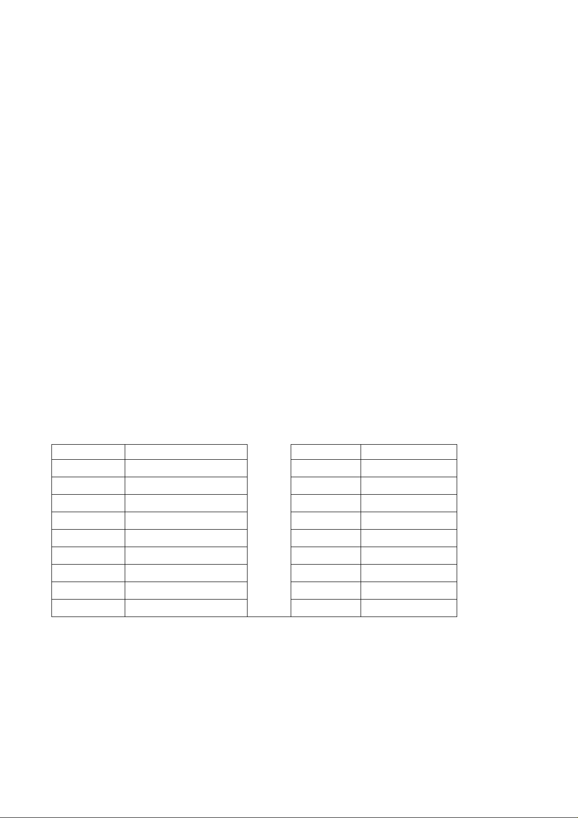
Table n.1
Min. Clearances inches (mm) Min. Clearances inches (mm)
20”
L1
L2
L3
L4
L5
L6
L7
L8
L9
(500)
1
9/16“ (40)
2
5/32” (55)
18” (457)
24” (610)
13” (330)
36
1/2“ (925)
1
9/16“ (40)- 3/4“ (20)
6
3/4” (172)
L10
L11
W
D
B1 (*)
B2 (*)
B3 (*)
B4 (*)
33 15/32” (850)
36“ (915)
35 1/16“ (890)
20
1/2“ (520)
1
31/32“ (50)
6“ (152)
1 9/16“ (40)
6“ (152)
(*) Note:
-B1 is the min. clearance between the front edge of the appliance and the front edge of the cabinet.
-B2 and B4 are the min. clearance between the left/right side edge of the appliance and the side wall (if
present).
-B3 is the min. clearance between the back edge of the appliance and the back wall.
Attaching the hotplate
To prevent liquids from leaking accidentally into the underlying storage space, the appliance is equipped with
a special gasket. To apply this gasket, carefully follow the instructions in Fig. 3. Lay out the protective sealing
strips along the edges of the opening in the bench top and carefully overlap the strip end. (See Fig. 3). insert
5

the hotplate into the bench top opening. With a screwdriver assemble the brackets to the hotplate bottom by
means of the screws . (See Fig. 4A-4B). Slide the hooks into position and secure them with the screws.
Trim the part of the sealing strips which extend beyond the hotplate base
Gas connection
Before connecting the appliance to the gas supply, first remove the plastic plug on which is pressfitted into the gas inlet union; to remove, just pull it off.
1. Check the ‘gas type’ sticker attached to the hotplate. Details of the injector sizes used are recorded on the
data plate located on the base of the appliance.
2. This appliance shall be installed in accordance with installation requirements of the local gas authority of
the appropriate installation code.
3. Before installing the hotplate consider the location of the gas supply and routing the gas line.(Refer fig.6)
4. For LPG models the gas supply is connected to the regulator which is supplied loose. The inlet connection
has a 1/2” B.S.P. male thread. IT IS ESSENTIAL THAT
THE ELBOW ON THE APPLIANCE BE HELD FIRMLY WITH A SPANNER WHEN CONNECTING THE
SUPPLY. DO NOT OVER TIGHTEN. The regulated pressure For LPG is 11” w.c. (See Fig. 5).
5. For NG models the gas supply is connected to the regulator which is supplied loose. The inlet connection
has a 1/2” B.S.P. male thread. IT IS ESSENTIAL THAT
THE ELBOW ON THE APPLIANCE BE HELD FIRMLY WITH A SPANNER WHEN CONNECTING THE
SUPPLY. DO NOT OVER TIGHTEN. The regulated pressure For NG is 4” w.c. (See Fig. 5).
6. For gas inlet position of appliance refer Fig 5, 6 and 7. After installing the gas supply and making all
connections check thoroughly for possible leaks. Turn all control knobs on the unit to ‘OFF’ position. Open
the valve on the gas supply. Using a soap and water solution check each gas connection one at the time, by
brushing the solution over the connection. Presence of bubbles will indicate a leak. Tighten the fitting and recheck for leaks. If it is not possible to correct the leak, replace fitting. Under no circumstances use matches
or flame for checking leaks.
It is essential that the gasket and the pressure test point stopper are properly installed to avoid gas leakage
7.To checking inlet pressure at the appliance operate as follow:
a) Disconnect electric power before pressure checking be carried out.
b) Take off one of the gas burner cap and the relative flame spreader in order to get access to the
burner injector.
c) Put in position the pressure detector directly on the burner injector afterward open the relative burner
knob at maximum position keeping it pressed, then measure the outlet pressure from the burner
injector.
d) Once the pressure checking has been carried out, replace the burner cap and flame spreader in the
correct and original position and re-connect electric power to the appliance.
8. Turn on appliance control cock and light each burner. Check for a clear blue flame without yellow tipping.
If burners show any abnormalities check that they are located properly and in line with the injector nipple.
9. Sometimes the burners will not ignite immediately and seem to ‘blow’ slightly when they do ignite. This
usually due to air in the gas lines, which will clear itself within seconds.
10. If after following the instructions given, satisfactory performance cannot be obtained, contact the local
gas authority for advice and assistance.
11. WARNING – If the surface is cracked, switch off the appliance to avoid the possibility of electric shock
12. Metallic Objects such as knives, forks, spoons and lids should not be placed on the hob surface since
they can get hot
13. A mean for disconnection, having a contact separation of at least 3mm in all poles, must be incorporated
in the fixed wiring.
6

Electrical connection
The appliance is equipped with a 4 ft. (1.2 m.) flexible metal cable with 4 wires ready for connection to a
dedicated 4 wire grounded power supply/junction box: (fig.
Voltage 120/208 V a.c., Frequency 60Hz. Max Current: 2800W /13,5 A
Voltage 120/240 V a.c., Frequency 60Hz. Max Current: 3700W /15,5 A
Black wire
Red wire
White wire
Green wire
: connect to L1 (hot)
: connect to L2 (hot)
: connect to N (neutral)
: connect to GND (ground)
A dedicated line and junction box should be used to connect the oven to a 20 A circuit.
Wiring diagrams Fig. 20.
Room ventilation – Location and venting.
ATTENTION: An exhaust fan may be used with the appliance; in each case it shall be installed in
conformity with the national standards in force.
ATTENTION: Exhaust hood operation may affect other vented appliances; in each case it shall be
installed in conformity with the national standards in force.
Conversion to different types of gas
Before carrying out any maintenance work, disconnect the appliance from the gas and electric
supply. For Natural Gas fit regulator assembly described in Fig. 5. For LP Gas fit assembly described
in fig. 5.
- CHANGING THE NOZZLES FOR USE WITH OTHER TYPES OF GAS:
To change the nozzles of the burners use the following procedure:
Lift up the burners and unscrew the nozzles ( Fig. 8) using an adjustable spanner of 7 mm and change the
nozzles with those designed for the new gas supply according to the information given in TABLE A shown
below.
TABLE A: Adapting to different types of gas
Burner Inj. size Gas Pressure Max Rate Min Rate By-pass size
1/100mm Type [i.w.c.] [BTU/h] [W] [BTU/h] [W] [1/100mm]
Semi-Rapid
Rapid
Inner 80 NG 4” 2700 791 900 264 Regulated
Dual 50 LP(Propane) 11” 2700 791 900 264 29
burner Outer N°2 x 130 NG 4” 15000 4394 4500 1318 Regulated
N°2 x 83 LP(Propane) 11” 15000 4394 4500 1318 65
CAUTION: save the orifices removed from the appliance for future use
117 NG 4” 6000 1759 1500 439 Regulated
73 LP(Propane) 11” 6000 1759 1500 439 36
155 NG 4” 10200 2991 2500 732 Regulated
98 LP(Propane) 11” 10200 2991 2500 732 47
Regulation of burners
Regulation of the "MINIMUM" on the burners
To regulate the minimum on the burners carry out the following procedure indicated below:
1) Turn on the burner and put the knob onto position MINIMUM ( small flame ).
2) Remove the knob ( Fig. 10) of the tap which is set for standard pressure. The knob is found on the bar of
the tap itself.
3) Beside the tap bar on the work top, use a small screwdriver that fits the screw (gold) found on the lower
part of the tap and turn the fixing screw to the right or left until the flame of the burner is regulated in the most
suitable way to MINIMUM.
4) Make sure that that the flame does not go out when changing the position quickly from MAXIMUM to the
MINIMUM position.
ATTENTION: The regulation described above can be carried out only with burners using natural gas,
while with burners using propane gas the screw must be fully screwed in, in a clockwise direction.
7

Adaptation of the pressure regulator for use with different type of gas
The pressure regulator supplied with the appliance is a convertible type pressure regulator for use with
Natural Gas at a nominal outlet pressure of 4” w.c. or LP gas at a nominal outlet pressure of 11” w.c. and it is
pre-arranged from the factory to operate with one of these gas/pressure as indicated in the pre-arranging
labels affixed on the appliance, package and Instruction booklet.
To convert the regulator for use with the other gas different from which one it is pre-arranged it is enough
perform the following operations:
1) Unscrew by hand the upper metal stopper of the regulator (Fig. 5).
2) Unscrew by hand the white plastic piece screwed under the above mentioned metal stopper, afterward
screw it again in opposite way under the metal stopper (for gas reference see the written “LP” and “NAT” with
relative indicating arrows on the white piece).
3) Screw again by hand the metal stopper in the original position on the regulator.
Operating in this way the gas regulator is converted for use with the other gas/pressure.
Descriptions
DESCRIPTIVE CAPTION FOR HOB (fig.9)
1. Dual burner
2 Rapid burner
3. Rear Induction element
4. Front induction element
5. Semi-rapid burner
6. Dual out burner control knob
7. Dual in burner control knob
8. Rapid burner control knob
9. Medium burner control knob
10. Front Induction element control knob
11. Rear Induction element control knob
Service & maintenance instructions
Service and maintenance only to be carried out by an authorised person
To replace parts such as burners, valves and electric components, the hotplate must be removed from the
bench top by releasing the attachment hooks, loosening the attachment screws of each burner, unscrewing
the hotplate attachments nuts which are visible at the bottom of the surface, removing the hotplate top and
finally replacing the defective parts.
Note: if the valves must be replaced, first disassemble the ignitions switches wires.
It is recommended to replace the valve gaskets each time the valve is replaced, thus ensuring a perfect seal
between the body and the gas train.
WARNING: Disconnect power before servicing unit.
For the location of the wall receptable for the connection of the three-pin earthed plug of the
appliance, see indications given in Fig. 1- 2
WARNING: After first installation of the appliance or after any service intervention concerning main
gas parts of the appliance, make the leak test using water with soap on the gas connections in order
to verify the correct installation. Do not use fire for gas leak testing.
User instructions
IMPORTANT SAFETY INSTRUCTIONS
1 - Proper Installation - Be sure your appliance is properly grounded and installed by a qualified technician.
2 - Never Use your Appliance for Warming or Heating the Room.
3 - Do Not Leave Children Alone - Children should not be left alone or unattended in an area where
appliance is in use. They should never be allowed to sit or stand on any part of the appliance.
8

4 - Wear Proper Apparel - Loose-fitting or hanging garments should never be worn while using the
appliance.
5 - User Servicing - Do not repair or replace any part of the appliance unless specifically recommended in
the manual. All other servicing should be referred to a qualified technician.
6 - Storage in or on Appliance - Flammable materials should not be stored near surface units.
7 - Do Not Use Water on Grease Fires - Smother fire or flame or use dry chemical or foam-type extinguisher.
8 - Use Only Dry Potholders - Moist or damp potholders on hot surfaces may result in burns from steam. Do
not let potholder touch hot heating elements. Do not use a towel or other bulky cloth.
9 - Use Proper Pan Size - This appliance is equipped with several, differently sized, induction elements.
Select cookware having flat bottoms, large enough to cover the surface unit heating element. Proper size
pots and pans will also improve efficiency.
10 - DO NOT TOUCH SURFACE UNITS OR AREAS NEAR UNITS - Surface units may be hot even though
they are dark in color. Areas near surface units may become hot enough to caus e burns.
11. Do Not Heat Unopened Food Containers - Build-up of pressure may cause container to burst and result
in injury..
12. Never Leave Surface Units Unattended at High Heat Settings - Boil-over causes smoking and greasy
spillovers that may ignite.
13. Do not use aluminum foil, aluminum liners or aluminum containers on the unit.
14. Cookware Handles Should Be Turned inward and Not Extend Over Adjacent Surface Units - To reduce
the risk of burns, and spillage due to unintentional contact with a pot/pan, which is used for cooking, the
handle of the piece should be positioned so that it is turned inward, and does not extend over adjacent
surface units.
15. Do not Cook on Broken Cooktop - If cooktop should break, cleaning solutions and spillovers may
penetrate the broken cooktop and create a risk of electric shock. Contact a qualified technician immediately.
16. Clean Cooktop With Caution - If a wet sponge or cloth is used to wipe spills on a hot cooking area, be
careful to avoid steam burns. Some cleaners can produce noxious fumes if applied to a hot surface.
CAUTION
Do not store items of interest to children in cabinets above or around the cooktop -children cli m bing on the
cooktop to reach items, could be seriously injured.
WARNINGS:
Keeping appliance area clear and free from combustible materials, gasoline and other flammable
vapors and liquid.
Do not store dangerous or flammable material in the cabinet areas above appliance; store them in a
safe place in order to avoid potential hazards.
9

For safe use of appliance, do not use it for space heating.
Do not use aerosol sprays in the vicinity of this appliance while it is in operation
For description of hotplates refer to installation instructions.
Using burners
A diagram is etched on the control panel above each knob which indicates which burner corresponds to that
knob. (fig.11-12-13-14)
Manual ignition:
Manual ignition is always possible even when the power is cut off or in the event of prolonged power failure.
Turn the knob that corresponds to the burner selected counterclockwise to the MAXIMUM position at the
etched star (large flame) and place a lit match up to the burner.
Burners fitted with a safety device (thermocouple):
Turn the knob that corresponds to the burner selected counterclockwise to the MAXIMUM position at the
etched star (large flame) and then press the knob down to activate the spark ignition. Once ignited, keep
pressing the knob for about 10 seconds to allow the flame to heat the thermocouple. If the burner does not
remain alight after releasing the knob repeat the above procedure,
Note: Dual burner is composed by two burner (inside and outside); each one operates under the relative gas valve
indipendently from the other one.
Note: It is recommended not to try to ignite the burner if the relative flame cap is not in the correct position
Tips for using burners correctly:
WARNING: During use of each gas burner(s) adjust the burner flame size properly so it does not
extend beyond the edge of the cooking utensil. This is an instruction based on safety considerations
- Use suitable pots for each burner (see Fig. 17 and Table B)
- When the liquid is boiling, turn down the knob to the MINIMUM position.
- Always use pots with a cover.
Table B
Burner Recommended pan diameters inches (mm)
Medium 551/8”- 1023/8”(140 – 260)
Large 707/8”- 1023/8” (180 – 260)
Dual 862/3”-1023/8” (220 – 260)
Correct usage of pans:
- Dry the bottom of the pan before placing it on the hotplate.
- Use pots with a flat, thick bottom, except for wok cooking.
- When using the burners, ensure that the handles of the pans are correctly positioned. Keep children away
from the appliance.
- When cooking foods with oil and fat, which are very flammable, the user should not leave the appliance
unattended.
WARNING: If the power is cut off, the burners can be lit with matches.
The burners equipped with a safety thermocouple can only be lit when the knob is in the MAXIMUM position
(large flame etching).
Note: The use of a gas cooking appliance produces heat and humidity in the room where it is installed.
Therefore, proper ventilation in the room is needed and natural ventilation openings must remain
unobstructed and activating the mechanical exhaust fan/range hood. Intensive and continuous use of the
appliance may require additional ventilation, for example by opening a window, or increasing the power of
the mechanical exhaust fan/range hood, if installed.
Using the ceramic induction elements
Safety Precautions - Read before operating your cooktop
Your induction-cooking unit has been designed for residential use and food preparation, and all of the safety
parameters have been designed accordingly.
The unit incorporates numerous safety devices and controls, a few of which will be mentioned below:
- A number of sensors monitor the temperature of the internal components. If any of these sensors senses
that the component temperature is above the limit, the power output of the unit will automatically be reduced,
10
 Loading...