


Bertazzoni PROF365QXE, MAST365QXE, PROF304QXE, PROF304QBXT, MAST366QBXT Installation Manual
...
BERTAZZONI
INSTALLATION MANUAL & USER
GAS COOKTOP
3100513
WWW.BERTAZZONI.COM

/ Table of contents
TABLE OF CONTENTS
INSTALLATON
WARNINGS ___________________________________________________________________
DATA RATING LABEL ___________________________________________________________
BEFORE INSTALLATION ________________________________________________________
VENTILATION PREPARATION ____________________________________________________
SPECIFICATIONS ______________________________________________________________
CLEARENCE DIMENSIONS ______________________________________________________
INSTALLATION REQUIREMENTS _________________________________________________
Electrical ___________________________________________________________________
Gas ________________________________________________________________________
ELECTRICAL CONNECTION _____________________________________________________
WIRING DIAGRAM _____________________________________________________________
GAS CONNECTION _____________________________________________________________
Manual shut-off valve _________________________________________________________
Flexible connections __________________________________________________________
Pressure test-point stopper valve _______________________________________________
Pressure regulator ____________________________________________________________
INSTALLATION ________________________________________________________________
Unpackaging the rangetop_____________________________________________________
Installing the worktop frontguard ________________________________________________
Installing the island trim _______________________________________________________
Installing backguard (optional) __________________________________________________
GAS CONVERSION _____________________________________________________________
INSTALLATION CHECKLIST ______________________________________________________
FINAL PREPARATION ___________________________________________________________
BERTAZZONI SERVICE _________________________________________________________
4
4
6
6
7
7
9
10
10
10
10
11
12
12
12
12
13
14
14
14
15
15
16
18
18
19
USER _______________________________________________________________________
WARNINGS ____________________________________________________________________
WORKTOP AND KNOBS LAYOUT _________________________________________________
GAS COOKTOP ________________________________________________________________
ELECTRIC GRIDDLE ____________________________________________________________
KEEPING YOUR BERTAZZONI CLEAN _____________________________________________
TROUBLESHOOTING ___________________________________________________________
TWO YEARS LIMITED WARRANTY ________________________________________________
20
20
22
23
25
26
27
28
2

/ Models
Models
MAST366QBXT
MAST365QBXT
MAST365QXE
PROF366QBXT
PROF365QBXT
PROF365QXE
MAST304QBXT
MAST304QXE
PROF304QBXT
PROF304QXE
Models
3
/ Warnings
WARNINGS
To ensure proper and safe operation, the appliance must be properly installed and grounded by a
qualifi ed technician. DO NOT attempt to adjust,
repair, service, or replace any part of your appliance unless it is specifi cally recommended in
this manual. All other servicing should be referred
to a qualifi ed servicer. Have the installer show you
the location of the gas shutoff valve and how to
shut it off in an emergency. A certifi ed technician
is required for any adjustments or conversions to
Natural or LP gas.
FOR THE INSTALLER: Before installing the Bertazzoni appliance, please read these instructions
carefully. This appliance shall be installed in accordance with the manufacturer’s installation instructions.
IMPORTANT: Leave these instructions with the
owner, who should save them for local inspector’s
use and for future reference. DO NOT remove
permanently affi xed labels, warnings, or plates
from product. This may void the warranty.
Installation must conform with all local codes. In
the absence of codes:
• United States: installation must conform with
the National Fuel Gas Code ANSI Z223.1
INFPA54
• Massachusetts: All gas products must be
installed by a “Massachusetts” licensed
plumber or gasfi tter. A “T” type handle manual
valve must be installed in the gas supply line
to the appliance.
• Canada: Installation must be in accordance
with the current CAN/CGA B149.1 & 2 Gas
Installation codes and/or local codes. Electrical
installation must be in accordance with the
current CSA C22.1 Canadian Electrical Codes
Part 1 and/or local codes.
This cooktop is NOT designed for installation in
manufactured (mobile) homes or recreational
park trailers.
DO NOT install this range outdoors.
This appliance must be properly grounded.
Grounding reduces the risk of electric shock by
providing a safe pathway for electric current in the
event of a short circuit.
Warning!
To avoid risk of property damage, personal
injury or death; follow information in this manual exactly to prevent a fi re or explosion.
WARNING!
If the information in these instructions is
not followed exactly, a fi re or explosion may
result causing property damage, personal
injury or death.
- Do not store or use gasoline or other fl ammable
vapors and liquid in the vicinity of this or any
other appliance.
- WHAT TO DO IF YOU SMELL GAS
•Do not try to light any appliance.
•Do not touch any electrical switch.
•Do not use any phone in your building.
•Immediately call your gas supplier from a
neghbor’s phone. Follow the gas supplier’s
instructions.
•If you cannot reach your gas suppliers, call
the fi re department.
- Installation and service must be performed by
a qualifi ed installer, service agency or the gas
supplier
WARNING!
Never Operate the Top Surface Cooking
Section of this Appliance Unattended.
- Failure to follow this warning statement could
result in fi re, explosion, or burn hazard that could
cause property damage. personal injury, or death.
- If a fi re should occur, keep away from the
appliance and immediately call your fi re depart-
ment.
DO NOT ATTEMPT TO EXTRINGUISH AN OIL/
GREASE FIRE WITH WATER
DANGER!!! ELECTRIC SHOCK HAZARD!!!
To avoid risk of electrical shock, personal injury
or death, verify that the appliance has been properly grounded in accordance with local codes or
in absence of codes, with the National Electrical
Code (NEC). ANSI/NFPA 70- latest edition.
DANGER!!! GAS LEAK HAZARD!!!
To avoid risk of personal injury or death, leak-testing of the appliance must be conducted according to the manufacturer’s instructions. Before
placing appliance in operation, always check for
gas leaks with water and soap solution.
DO NOT USE AN OPEN FLAME TO
CHECK FOR GAS LEAKS.
4

WARNING:
Cancer and Reproductiv Harm www.P65Warnings.ca.gov
.
/ Warnings
5

/ Data rating label / Before installation
DATA RATING LABEL
The data rating label shows the model and serial
number of the cooktop. It is located under the ran-
getop and in the last page of this manual.
BEFORE INSTALLATION
• This appliance shall only be installed by an
authorized professional.
• This appliance shall be installed in accordance
with the manufacturer’s installation
instructions.
• This appliance must be installed in accordance
with the norms & standards of the country
where it will be installed.
• The installation of this appliance must conform
to local codes and ordinances. In the absence
of local codes, Installations must conforms to
American National Standards, National Fuel
Gas Code ANSI Z223.1 – latest edition/NFPA
54 or B149.1.
• The appliance, when installed, must be
electrically grounded in accordance with local
codes or, in the absence of local codes, with
the National Electrical Code, ANSI/NFPA 70.
If local codes permit, a fl exible metal appliance
connection conduit with the new AGA or CGA certifi ed design, max. 5 feet (1,5 m) long, ½” I.D. is
recommended for connecting this appliance to the
gas supply line. Do not bend or damage the fl exi-
ble connector when moving the appliance.
This appliance must be used with the pressure
regulator provided.
The regulator shall be properly installed in order to
be accessible when the appliance is installed in its
fi nal location. The pressure regulator must be set
for the type of gas to be used. The pressure regulator has ½” female pipe thread. The appropriate
fi tting must be determined based on the size of
your gas supply line, the fl exible metal connector
and the shutoff valve.
The appliance must be isolated from the gas supply piping system by closing its individual manual
shutoff valve during any pressure testing of the
gas supply piping system at test pressures equal
to or less than 1/2 PSI (13,8” w.c. or 3,5 kPa).
A manual valve shall be installed in an accessible
location in the gas line external to the appliance
for the purpose of turning on or shutting off gas to
the appliance.
Type of gas
This cooktop can be used with Natural or LP/Propane gas. The range is shipped from the factory
for use with the gas indicated on the rating label
positioned on the lower face of the control panel
and in the last page of this manual. A step by step
conversion procedure is also included in this manual and in each conversion kit.
Gas pressure
The maximum inlet gas supply pressure incoming to the gas appliance pressure regulator is
1/2 PSI (13,8’’ iwc or 3,5 kPa). The minimum gas
supply pressure for checking the regulator setting
shall be at least 1“ iwc (249 Pa) above the inlet
specifi ed manifold pressure to the appliance; this
operating pressure is 4” iwc (1.00 kPa) for Natural
Gas and 10” iwc (2.50 kPa) for LP Gas.
Room ventilation
An exhaust fan may be used with the appliance;
in each case it shall be installed in conformity
with the appropriate national and local standards.
Exhaust hood operation may aff ect other vented
appliances; in each case it shall be installed in
conformity with the appropriate national and local
standards.
Warning
This appliance should not be installed with a
ventilation system that directs air in a downward
direction toward the range. This type of ventilation system may cause ignition and combustion
problems with the appliance resulting in personal
injury, property damage, or unintended operation.
Ventilating systems that direct the air upwards do
not have any restriction.
Do not use aerosol sprays in the vicinity of
this appliance while it is in operation.
All opening and holes in the wall and fl oor, back
and under the appliance shall be sealed before
installation of the appliance.
6
VENTILATION PREPARATION
/ Ventilation preparation / Specifi cations
This cooktop will best perform when installed with
Bertazzoni exhaust hoods. These hoods have
been designed to work in conjunction with the
Bertazzoni cooktop and have the same fi nish for
a perfect look.
Before installation of the exhaust hood, consult local or regional building and installation codes for
additional specifi c clearance requirements.
Refer to the cooktop hood installation instructions
provided by the manufacturer for additional information.
Select Hood and Blower Models:
• For wall installations, the hood should be
equal or larger width than the cooktop. Where
space permits, a hood larger than the range
may be desirable for improved ventilation
performance.
• For island installations, the hood width should
overhang the cooktop by a minimum of 3” (76
mm) on each side.
Hood Placement:
• For best removal of smoke and odors, the
lower edge of the hood should be installed
between 25 1/2” (65 cm) and 31 1/2” (80 cm)
above the range cooking surface.
• If the hood contains any combustible materials
(i.e. a wood covering), it must be installed at a
minimum of 36” (914 mm) above the cooking
surface.
Consider Make-Up Air:
Due to the high volume of ventilation air, a source of outside replacement air is recommended.
This is particularly important for tightly sealed
and insulated homes. A qualifi ed heating and
ventilating contractor should be consulted.
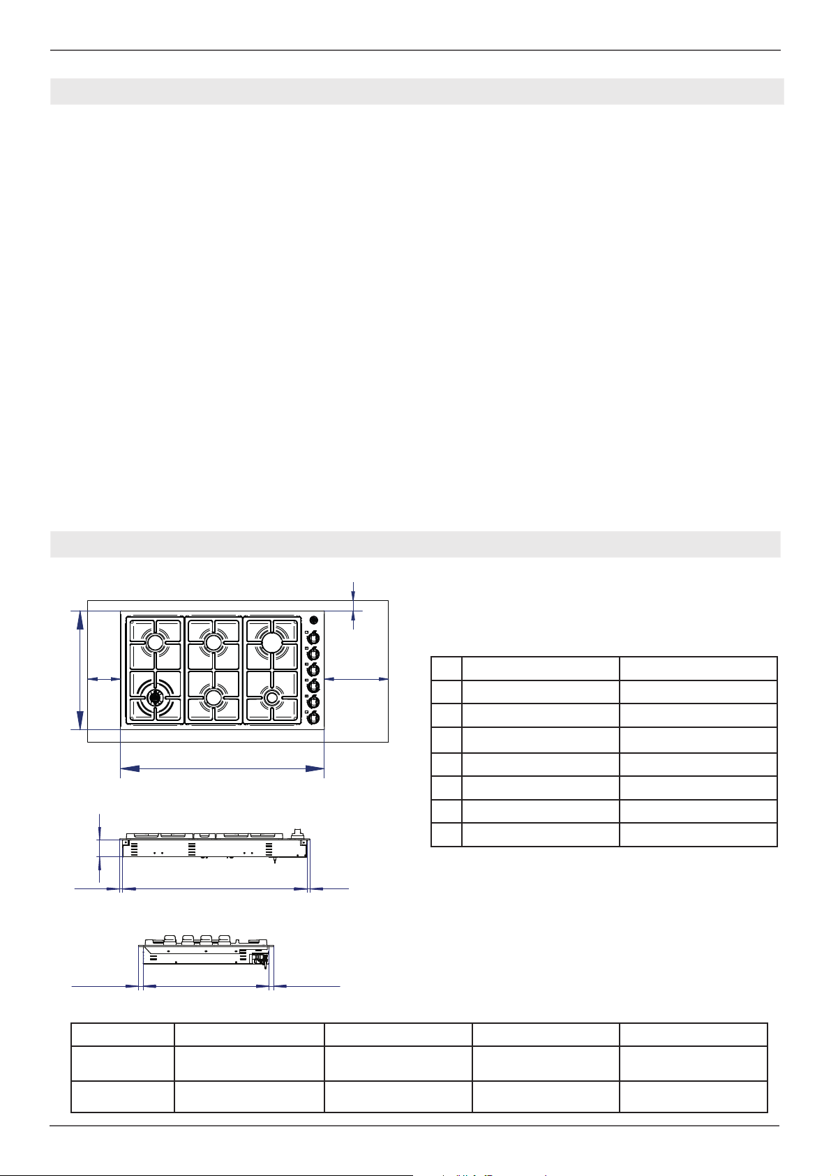
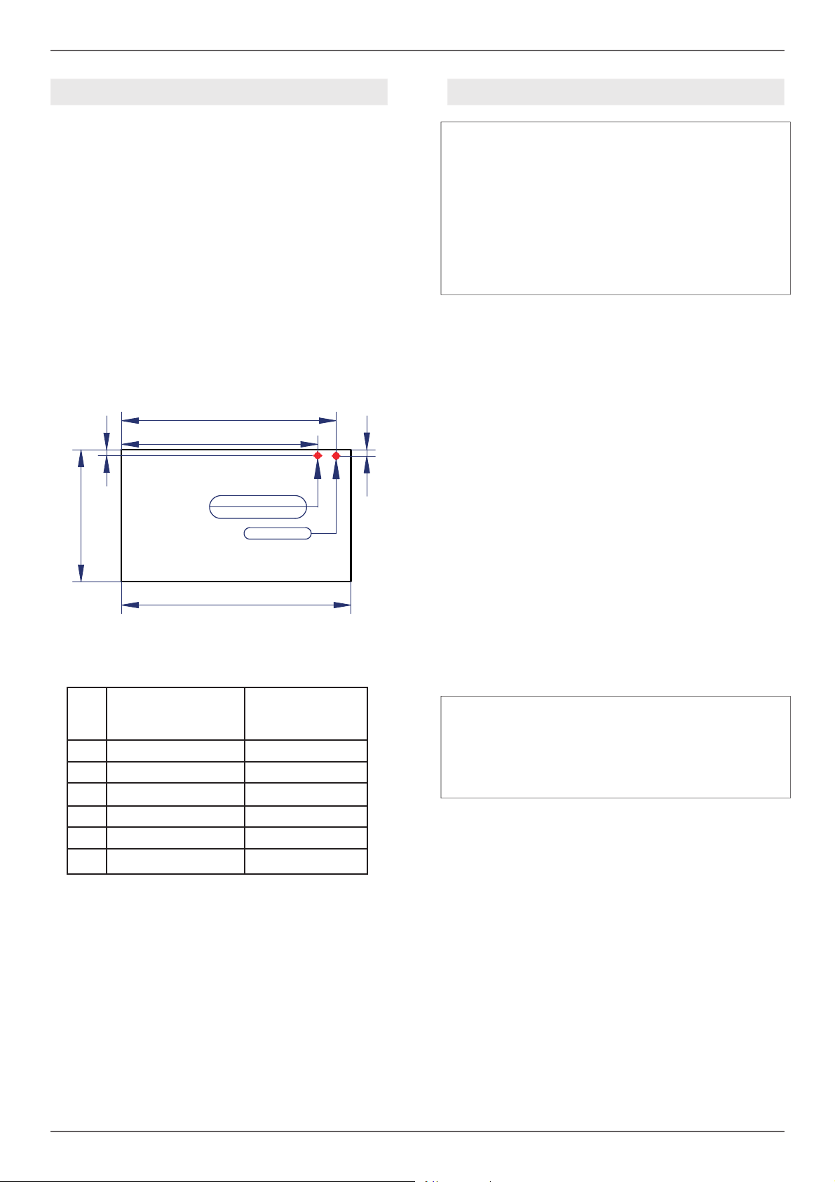
SPECIFICATIONS
B3
D
BB
W
FRONT
M
NPQ
SIDE
cooktop 30” cooktop 36”
M 2” 5/8 (6,6 cm) 2” 5/8 (6,6 cm)
N 1/2” (1,2 cm) 3/4” (1,9 cm)
P 28” 9/16 (72,5 cm) 35” 1/4 (89,5 cm)
Q 7/16” (1,1 cm) 7/16” (1,1 cm)
3/4”(1,8 cm) 3/4”(1,8 cm)
R
19” 13/16(50,3 cm) 19” 13/16(50,3 cm)
S
3/4”(1,8 cm) 3/4”(1,8 cm)
T
R
cooktop 30” 29” 7/16 (74,8 cm) 21” 1/4 (54 cm)
cooktop 36” 36” 7/16 (92,5 cm) 21” 1/4 (54 cm)
S
W D B1 - B2 B3
T
6”(15,2 cm) 1” 3/4 (4,5 cm)
6”(15,2 cm) 1” 3/4 (4,5 cm)
7

/ Specifi cations
s
Burner
urner Injector
Auxiliary
Semi-rapid
Rapid
Dual burner
Injector
diam.[mm]
0.92
0.56
1.17
0.73
1.55
0.98
0.80+1.30
0.50+0.83
Gas
as
Type
NG
LP (Propane)
NG
LP (Propane)
NG
LP (Propane)
NG
LP (Propane)
Pressure
Pressure Max Rate Min Rate
[iwc]
4’’
10’’
4’’
10’’
4’’
10’’
4’’
10’’
Max Rate
[Btu/hr]
3,750
3,750
6,000
6,300
10,400
11,400
17,000
18,800
[W]
1,098
1,098
1,729
1,845
2,046
3,339
4,980
5,507
Min Rate
[Btu/hr]
900
900
1,500
1,500
3,700
3,700
900
900
[W]
264
264
439
439
1,084
1,084
264
264
See use and care manual for the layout of the surface burners of your rangetop
Cabinet Preparation
1. To ensure professional results, the cabinet and
countertop openings should be prepared by a
qualifi ed cabinet worker.
2. The clearances shown in fi gure are required.
3. The gas and electrical supply must be located in an area that is accessible without requiring
removal of the cooktop. The appliance electrical
power cord and gas pipe connection are located
on the left rear.
By-pass
-pas
diam.[mm]
Regulated
0.29
Regulated
0.37
Regulated
0.58
Regulated
0.29/0.65
• Prepare the fi nished opening for the rangetop
according to dimensions shown in the
illustration on the follows page.
• The platform must include a cut-out at the right
rear for electrical and gas supply connections.
It must be level to ensure the cooking surface
is level. Refer to the chart below for minimum
base support.
8
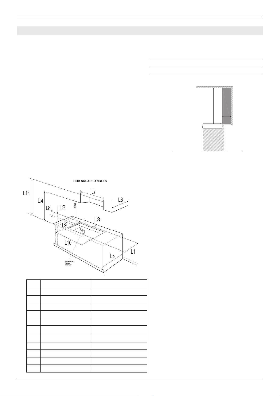
CLEARENCES DIMENSIONS
/ Clearence dimensions
Installation adjacent to kitchen cabinets
This cooktop may be installed directly adjacent to
existing countertop high cabinets (36” or 91.5 cm
from the fl oor).
For the best look, the worktop should be level with
the cabinet countertop. This can be accomplished
by raising the unit using the adjustment spindles
on the legs.
ATTENTION: the cooktop CANNOT be installed
directly adjacent to kitchen walls, tall cabinets, tall
appliances, or other vertical surfaces above 36”
(91.4 cm) high. The minimum side clearance in
such cases is 6” (15.2 cm).
Wall cabinets with minimum side clearance must
be installed 18” (45.7 cm) above the countertop
with countertop height between 35 ½” (90.2 cm)
and 37 ¼” (94.6 cm). The maximum depth of wall
cabinets above the rangetop shall be 13” (33.0
cm).
Cabinet
Metal hood
min 25” 1/2 (65 cm)
B
H
min 12” (30,50 cm)
B
H
Shaded area behind cooktop indicates minimum
clearance to combustible surfaces, combustible
materials cannot be located within this area.
12” (305 mm) min. to combustible surface with
Flush Island Trim
COOKTOP 30” COOKTOP 36”
L1 20” 1/2 (52 cm) 20” 1/2 (52cm)
L2 1” 9/16 (4 cm) 1” 9/16 (4cm)
L3 2” 3/16 (5,5cm) 2” 3/16 (5,5cm)
L4 18” (45,7cm) 18” (45,7cm)
L5 25” 3/16 (64 cm) 25” 3/16 (64 cm)
L6 13” (33cm) 13” (33cm)
L7 29” 7/16 (74,8cm) 36” 7/16 (92,5 cm)
For Flush Island installations, counter surface
should have a cantilever edge meeting the back
section of the Flush Island Trim accessory.
As defi ned in the “National Fuel Gas Code” (ANSI
Z223.1, Current Edition).
Clearances from non-combustible materials are
not part of the ANSI Z21.1
scope and are not certifi ed by CSA. Clearances of
less than 12” (305 mm) must be approved by the
local codes and/or by the local authority having
jurisdiction.
L8 3” 1/8 (8cm) 3” 1/8 (8cm)
L9 6” 1/4 (16cm) 6” 9/16 (16,6cm)
L10 28” 15/16 (73,5cm) 35” 5/8 (90,5cm)
L11 36” (91,5cm) 36” (91,5cm)
9
/ Clearence dimensions
TECHNICAL INSTALLATION INSTRUCTIONS
INSTALLING THE HOB ABOVE AN OVEN
The clearance between the hob and the
kitchen furniture or other installed appliances
must be enough to ensure suffi cient ventilation
and air discharge.
If installed above an oven, space must be
left between the bottom of the hob and the
top of the product installed below to allow for
ventilation of the entire compartment (see
fi gure).
The oven must be equipped with a cooling
device. The manufacturer shall bear no
liability in the event of the hob being installed
in combination with an oven from another
manufacturer.
The countertop must be able to withstand temperatures up to 300°F (149°C).
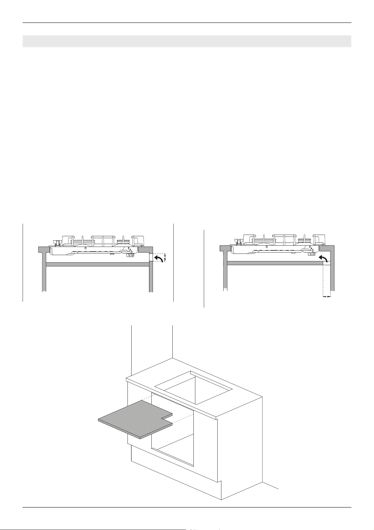
INSTALLING THE HOB ABOVE A CUPBOARD
OR DRAWERS
The clearance between the hob and the
kitchen units must be enough to ensure
suffi cient ventilation and air discharge. If there
are other units/furniture (side walls, drawers,
etc.), dishwashers or fridges under the hob, a
double-layer wooden base must be installed
at least 20 mm from the bottom of the hob
to avoid any accidental contact. It must only
be possible to remove the double-layer base
using special tools.
The countertop must be able to withstand temperatures up to 300°F (149°C).
(40mm)
1” 9/16
1” 9/16
(40mm)
10
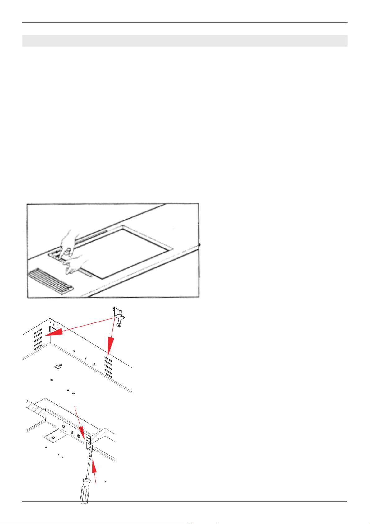
HOB FASTENING
In order to prevent accidental water ingress into
the unit below, the appliance is fi tted with a special
gasket.
1)Lay out the protective sealing strips along
the edges of the opening in the bench top and
carefully overlap the strip end.
2)Insert the hotplate into the bench top opening.
3) With a screwdriver assemble the brackets A to
the hotplate bottom by means of the screws.
4) Slide the hooks into position and secure them
with the screws.
5)Trim the part of the sealing strips which extend
beyond the hotplate base
/ Clearence dimensions
11
/ Installation requirements / Electrical connection
INSTALLATION REQUIREMENTS ELECTRICAL CONNECTION
ELECTRICAL
A properly-grounded horizontally- mounted electrical receptacle should be installed.
Check all local code requirements.
GAS
An agency-approved, properly-sized manual shutoff valve should be installed.
To connect gas between shut-off valve and regula-
tor, use agency-approved, properly sized fl exible
or rigid pipe. Check all local code requirements.
A
C
D
ELECTRIC
L1
CONNECTION
GAS INLET
B
Warning!
ELECTRICAL SHOCK HAZARD
Disconnect electrical power at the circuit breaker box or fuse box before installing the appliance.
Provide appropriate ground for the appliance.
Use copper conductors only.
Failure to follow these instructions could result in serious injury or death.
This unit is manufactured for a polarized, grounded 120 volt/60 Hz, 16 amp system.
Electric power consumption is about 200 W for
36”, 1200W for 48”
The minimum of 102 VAC is required for proper
operation of gas ignition systems.
The circuit must be grounded and properly polarized.
The unit is equipped with a SJT power cord and
a NEMA 5-15P plug. In case of replacement, the
power cord shall be replaced with one of the same
type, size and length.
L10
COOKTOP
30”
A 26”5/8(677mm) 33”5/16(847mm)
B 15/16(24mm) 15/16(24mm)
C 23”3/4(604mm) 30”1/2(774mm)
D 7/8(23mm) 7/8(23mm)
L1 20”1/2(520mm) 20”1/2(520mm)
L10 28”15/16(735mm) 35”5/8(905mm)
COOKTOP
36”
Warning!
Electrical grounding
This appliance is equipped with a three-prong
plug for your protection against shock hazard and
should be plugged directly into a properly grounded socket. Do not cut or remove the grounding
prong from this plug.
Caution
Label all wires prior to disconnecting when
servicing controls. Wiring errors can cause
improper and dangerous operation.
Verify proper operation after servicing.
For appliances equipped with a cord and plug,
do not cut or remove the ground prong. It must
be plugged into a matching grounding type receptacle to avoid electrical shock. If there is any
doubt as to whether the wall receptacle is properly
grounded, the customer should have it checked
by a certifi ed electrician.
Do not use an extension cord with the gas cooktop.
Plan the installation so that the power connection
is accessible from the front of the cabinet.
12
/ Wiring diagram
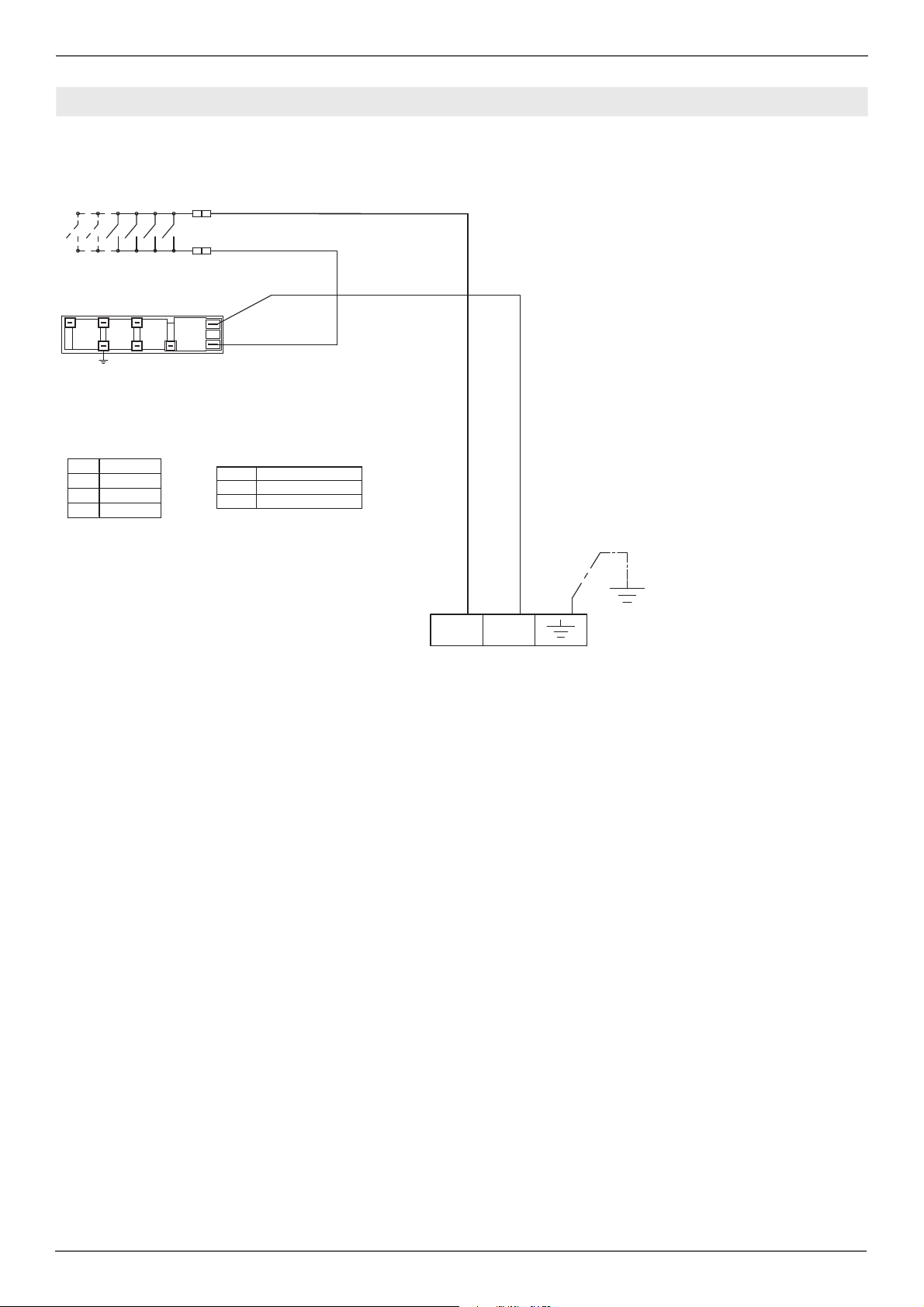
WIRING DIAGRAM
The electric wiring diagrams and schematics are attached behind the rangetop, and should not be removed
except by a service technician, then replaced after service.
Q
*
&2/2856
6LPE 'HVFULSWLRQ
JU *UHHQ HDUWK
Q %ODFNOLQH
EL : KLWH QHXWUDO
,*1
Q
EL
/(*(1'$
6LPE 'HVFULSWLRQ
,*1 ,JQLWLRQ0LFURVZLWFKHV
* 6SDUN*HQHUDWRU
EL
*9
/
1
0
13
/ Gas connection
GAS CONNECTION
Warning!
DO NOT USE AN OPEN FLAME WHEN
CHECKING FOR LEAKS!
Leak testing of the appliance shall be conducted
according to the manufacturer’s instructions. Before placing the oven into operation, always check
for leaks with soapy water solution or other acceptable method.
Check for gas leakage with soapy water solution or
other acceptable methods in all gas connections
installed between inlet gas pipe of the appliance,
gas regulator, till to the manual shut-off valve.
All gas connections must comply with national and
local codes. The gas supply line (service) must
be the same size or greater than the inlet line of
the appliance. This cooktop uses a 1/2” NPT inlet
(see drawing below for details of gas connection).
On all pipe joints use appropriate sealant resistant
to gas to joint the adapter to rangetop manifold
use only the blue gasket supplied.
If necessary, the appliance must be converted by
the dealer, by a factory-trained professional or by
a qualifi ed licensed plumber or gas service com-
pany.
FLEXIBLE CONNECTIONS
In case of installation with fl exible couplings and/
or quick-disconnect fi ttings, the installer must use
a heavy-duty, AGA design-certifi ed commercial
fl exible connector of at least 1/2” (1.3 cm) ID NPT
(with suitable strain reliefs) in compliance with
ANSI Z21.41 and Z21.69 standards.
In Massachusetts: The unit must be installed
with a 36” (3-foot) long fl exible gas connector.
In Canada: use CAN 1-6.10-88 metal connec-
tors for gas appliances and CAN 1-6.9 M79 quick
disconnect device for use with gas fuel.
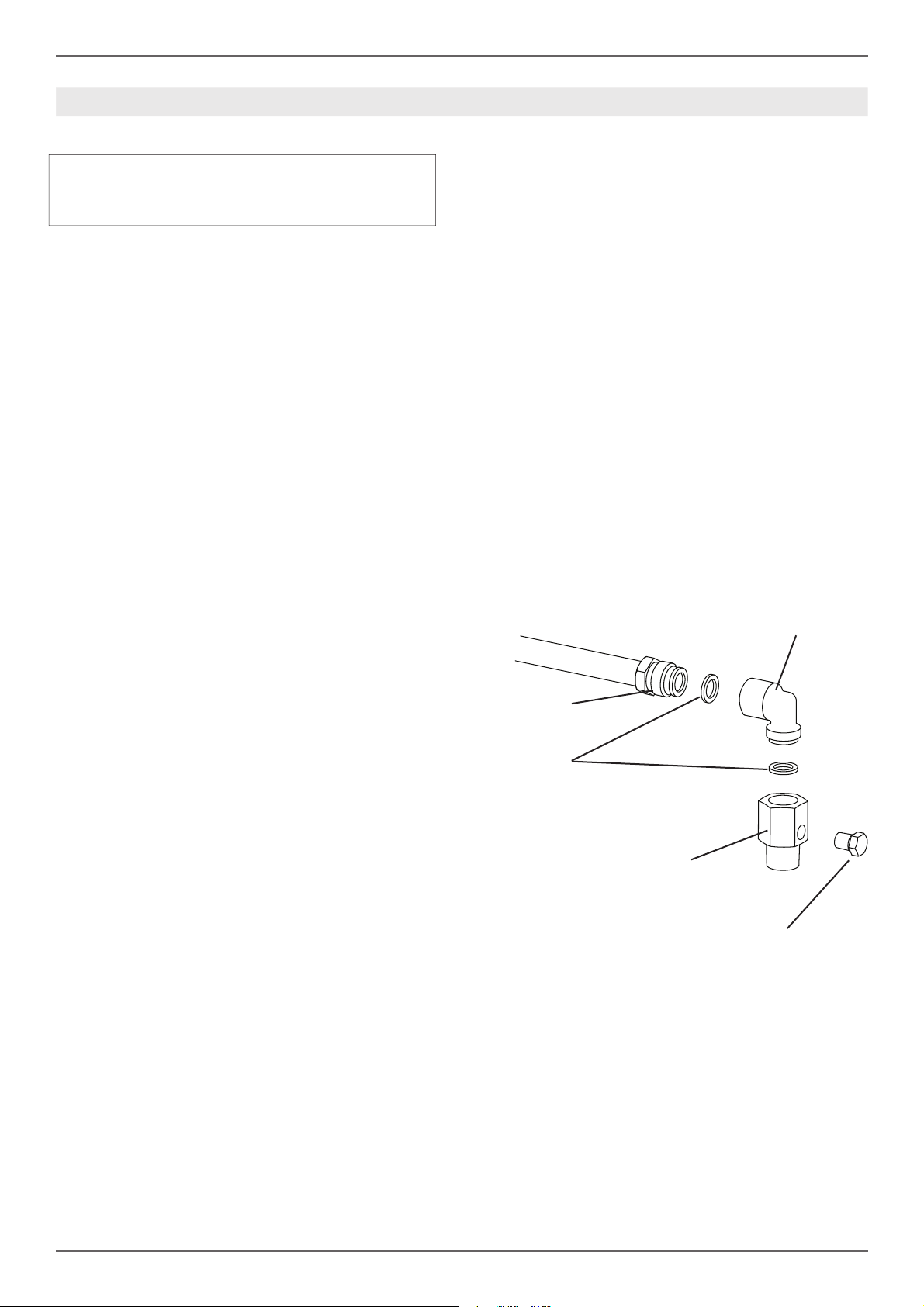
PRESSURE TEST-POINT STOPPER
VALVE
To avoid gas leaks, the pressure test-point stopper valve and gasket supplied with the range must
be installed on the gas fi tting at the back of the
range according to the diagram below.
ELBOW
Gas conversion is important for safe and eff ective
use of the appliance. It is the responsibility of the
dealer and the owner of the cooktop to perform
the appropriate gas conversion following the directions of the manufacturer.
THE GAS CONVERSION PROCEDURE IS
DESCRIBED IN THIS MANUAL AND IN THE
PACKAGE CONTAINING THE CONVERSION
NOZZLES SHIPPED WITH EVERY RANGE.
Please provide the service person with this manual before work is started on the range.
MANUAL SHUT-OFF VALVE
THIS VALVE IS NOT SHIPPED WITH THE APPLIANC AND MUST BE SUPPLIED BY THE INSTALLER.
The manual shut-off valve must be installed in the
gas service line between the gas hook-up on the
wall and the appliance inlet, in a position where it
can be reached quickly in the event of an emergency.
GAS PIPE
GASKET
GAS CONNECTION ADAPTOR
1/2’’NPT WITH PRESSURE TEST
POINT 1/8’’ NPT (TO BE FIXED
TOWARD EXTERNAL SIDE OF
THE APPLIANCE)
PRESSURE TEST-POINT
STOPPER
In Massachusetts: A ‘T’ handle type manual
gas valve must be installed in the gas supply line
to this appliance.
14
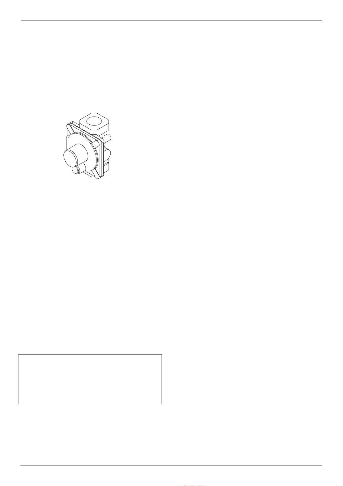
PRESSURE REGULATOR
Since service pressure may fl uctuate with local
demand, every gas cooking appliance must be
equipped with a pressure regulator on the incoming service line for safe and effi cient operation.
The pressure regulator shipped with the appliance has two female threads ½” NPT. The regulator
shall be installed properly in order to be accessible
when the appliance is installed in its fi nal position.
/ Gas connection
Manifold pressure should be checked with a manometer and comply with the values indicated below:
Natural gas 4.0” iwc
LP/Propane 10.0” iwc
Incoming line pressure upstream from the regulator must be 1” iwc higher than the manifold pressure in order to check the regulator.
The regulator used on this cooktop can withstand
a maximum input pressure of 1/2 PSI (13,8” iwc or
3,5 kPa) If the line pressure exceeds that amount,
a stepdown regulator is required.
The appliance, its individual shut-off valve, and
the pressure regulator must be disconnected from
the gas line during any pressure testing of that system at pressures in excess of 1/2 PSI (13,8” iwc
or 3,5 kPa).
The individuaL manual shut-off valve must be in
the OFF position during any pressure testing of
the gas supply piping system at test pressures
equal to or less than 1/2 PSI (13,8” iwc or 3,5 kPa).
Warning
Before carrying out any servicing operation disconnect the appliance from gas and electric
supply and extra appliance from fi nal installation
place in order to have access to the appliance for
proper servicing intervention.
15

/ Installation
INSTALLATION
APPLIANCE INSTALLATION
Unpacking the rangetop
• Remove all packing materials from the shipping
pallet but leave the adhesive-backed foam
layer over brushed-metal surfaces to protect it
from scratches until the range is installed in its
fi nalposition. Only the fi lm on the side panels
should be removed before inserting the range
between the cabinets.
• Examine the appliance after unpacking it. In
the event of transport damage, do not plug
it. Take pictures of the damage and report it
immediately to the freight forwarder.
• The grates, griddle plate, burner caps, and
oven racks should be removed to facilitate
handling.
•
Appliance Handling Safety
CAUTION
• Unit is heavy and requires at least two people
or proper equipment to move.
• Hidden surfaces may have sharp edges.
Use caution when reaching behind or under
appliance.
16
GAS CONVERSION
Warning!
Before carrying out this operation, disconnect the
appliance from gas and electricity.
Gas conversion shall be conducted by a factory-trained professional.
Call the customer service hotline to identify a fac-
tory-trained professional near your home.
The gas conversion procedure for this rangetop
includes 4 steps:
• Pressure regulator
• Surface burners
• Visual checks prior to closure of oven bottom
panel
• Adjustment of minimum setting
/ Gas conversion
LP
The conversion is not completed if all 4 steps have
not been concluded properly.
Before performing the gas conversion, locate the
package containing the replacement nozzle shipped with every range.
IMPORTANT: Each nozzle has a number indicating its fl ow diameter printed on the body. Consult
the table number 1 for matching nozzles to burners.
Save the nozzles removed from the rangetop for
future use.
Step 1: pressure regulator
The pressure regulator supplied with the appliance is a convertible type pressure regulator for use
with Natural Gas at a nominal outlet pressure of
4” iwc or LP gas at a nominal outlet pressure of
10”iwc. and it is pre-arranged from the factory to
operate with one of these gas/pressure as indicated in the labels affi xed on the appliance, package
and Instruction booklet.
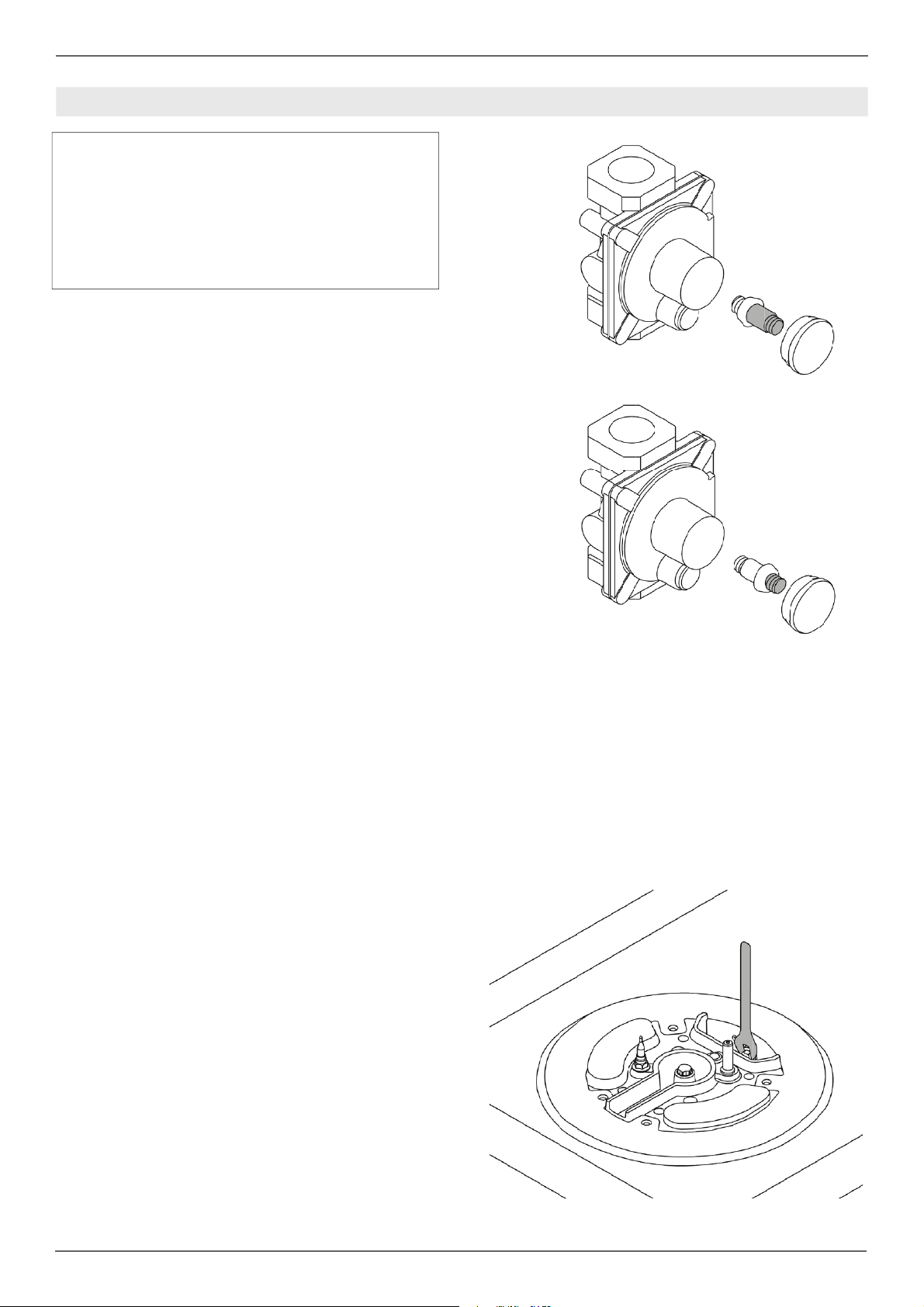
To convert the regulator for use with the other gas:
Unscrew by hand the upper cap of the regulator, remove the white plastic attachment from the
cap, reverse its direction and screw it again fi rm-
ly against the cap. The white plastic attachment
has arrows indicating the position for natural gas
(NAT) and LP gas (LP).
Screw by hand the metal cap in the original position on the regulator.
NAT
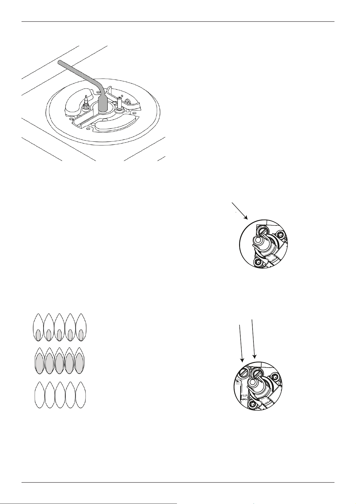
Step 2: surface burners
To replace the nozzles of the surface burners, lift
up the burners and unscrew the nozzles shipped
with the cooktop using a 7 mm (sochet wrench).
Replace nozzles using the conversion set supplied with the rcooktop or by a Bertazzoni authorized parts warehouse. Each nozzle has a number
indicating its fl ow diameter printed on the body.
Consult the table number 1 and matching nozzles
to burners.
17
/ Gas conversion
Step 3: visula checks
Surface burners
The burner fl ame color should be blue with no yel-
low on the tips. It is not uncommon to see orange
in the
fl ame color; this indicates the burning of airborne
impurities in the gas and will disappear with use.
With propane (LP) gas, slight yellow tips on the
primary icone are normal.
The fl ame should burn completely around the bur-
ner cap. If it doesn’t, check that the cap is positioned
correctly on the base and that the ports are not
blocked.
The fl ame should be stable with no excessive noi-
se or fl uttering.
Step 4: minimum fl ame adjustment
WARNING!
These adjustments should be made only for use
of the appliance with natural gas. For use with liquid propane gas, the choke screw must be fully
turned in a clockwise direction.
SURFACE BURNERS
Light one burner at a time and set the knob to the
MINIMUM position (small fl ame).
Remove the knob.
The cooktop is equipped with a safety valve. Using
a small-size slotted screwdriver, locate the choke
valve on the valve body and turn the choke screw
to the right or left until the burner fl ame is adjusted
to desired minimum.
Make sure that the fl ame does not go out when
switching quickly from the MAXIMUM to the MINIMUM position.
For the gas valve of dual burner the choke valve is
located on the valve body, the A screw adjust the
outer ring, the B screw adjust the inner ring.
yellow fl ames:
further adjustment is required
yellow tips on outer cones:
normal for LP gas
soft blue fl ames:
normal for natural gas
After performing all these visual checks, reinstall
the bottom panel of the oven compartment and
proceed to setting the minimum for each burner.
B
A
High Altitude Installation
Contact customer service for use at altitudes above 2,000 feet (610 meters).
18
 Loading...