


Bertazzoni KIN52MOD1XC, KIN70MOD1XB, KIN86MOD1XB User Manual
Libretto di Istruzioni |
|
|
IT |
||||||||
Bedienungsanleitung |
|
|
DE |
||||||||
Instructions Manual |
|
|
EN |
||||||||
Manuel d’Instructions |
|
|
FR |
||||||||
Gebruiksaanwijzing |
|
|
NL |
||||||||
Manual de instrucciones |
|
|
ES |
||||||||
Brugsvejledning |
|
|
DK |
||||||||
Käyttöohje |
|
|
|
|
FI |
||||||
Bruksanvisning |
|
|
|
NO |
|||||||
Bruksanvisning |
|
|
|
SE |
|||||||
Instrukcja Obsługi |
|
|
|
|
|
|
|
PL |
|||
|
|
|
|||||||||
KIN52MOD1XC
KIN70MOD1XB
KIN86MOD1XB

INDICE |
IT |
INFORMAZIONI SULLA SICUREZZA...................................................................................................................................... |
4 |
CARATTERISTICHE.............................................................................................................................................................. |
7 |
INSTALLAZIONE ................................................................................................................................................................... |
8 |
USO...................................................................................................................................................................................... |
10 |
PULIZIA E MANUTENZIONE................................................................................................................................................. |
11 |
INHALTSVERZEICHNIS |
DE |
SICHERHEITSINFORMATIONEN ......................................................................................................................................... |
13 |
CHARAKTERISTIKEN ......................................................................................................................................................... |
16 |
MONTAGE ........................................................................................................................................................................... |
17 |
BEDIENUNG........................................................................................................................................................................ |
19 |
REINIGUNG UND WARTUNG............................................................................................................................................... |
20 |
INDEX |
EN |
SAFETY INFORMATION....................................................................................................................................................... |
22 |
CHARACTERISTICS ........................................................................................................................................................... |
25 |
INSTALLATION.................................................................................................................................................................... |
26 |
USE ...................................................................................................................................................................................... |
28 |
CARE AND CLEANING......................................................................................................................................................... |
29 |
SOMMAIRE |
FR |
CONSIGNES DE SÉCURITÉ................................................................................................................................................. |
31 |
CARACTERISTIQUES......................................................................................................................................................... |
34 |
INSTALLATION.................................................................................................................................................................... |
35 |
UTILISATION ....................................................................................................................................................................... |
37 |
NETTOYAGE ET ENTRETIEN .............................................................................................................................................. |
38 |
INHOUDSOPGAVE |
NL |
VEILIGHEIDSINFORMATIE................................................................................................................................................... |
40 |
EIGENSCHAPPEN .............................................................................................................................................................. |
43 |
INSTALLATIE....................................................................................................................................................................... |
44 |
GEBRUIK ............................................................................................................................................................................. |
46 |
REINIGING EN ONDERHOUD.............................................................................................................................................. |
47 |
INDICE |
ES |
INFORMACIÓN DE SEGURIDAD.......................................................................................................................................... |
49 |
CARACTERÍSTICAS ........................................................................................................................................................... |
52 |
INSTALACIÓN ..................................................................................................................................................................... |
53 |
USO...................................................................................................................................................................................... |
55 |
LIMPIEZA Y MANTENIMIENTO............................................................................................................................................. |
56 |
2

INDHOLD |
DK |
OPLYSNINGER OM SIKKERHED......................................................................................................................................... |
58 |
APPARATBESKRIVELSE ................................................................................................................................................... |
61 |
INSTALLATION.................................................................................................................................................................... |
62 |
BRUG ................................................................................................................................................................................... |
64 |
RENGØRING OG VEDLIGEHOLDELSE ............................................................................................................................... |
65 |
SISÄLTÖ |
FI |
TURVALLISUUSTIETOJA ..................................................................................................................................................... |
67 |
MITAT JA OSAT .................................................................................................................................................................. |
70 |
ASENNUS ............................................................................................................................................................................ |
71 |
KÄYTTÖ ............................................................................................................................................................................... |
73 |
PUHDISTUS JA HUOLTO ..................................................................................................................................................... |
74 |
INNHOLD |
NO |
SIKKERHETSINFORMASJON .............................................................................................................................................. |
76 |
EGENSKAPER..................................................................................................................................................................... |
79 |
INSTALLASJON................................................................................................................................................................... |
80 |
BRUK ................................................................................................................................................................................... |
82 |
RENGJØRING OG VEDLIKEHOLD....................................................................................................................................... |
83 |
INNEHÅLL |
SE |
SÄKERHETSINFORMATION ................................................................................................................................................ |
85 |
EGENSKAPER..................................................................................................................................................................... |
88 |
INSTALLATION.................................................................................................................................................................... |
89 |
ANVÄNDING........................................................................................................................................................................ |
91 |
NGÖRING OCH UNDERHÅL ................................................................................................................................................ |
92 |
SPIS TREŚCI |
PL |
INFORMACJE DOTYCZĄCE BEZPIECZEŃSTWA................................................................................................................ |
94 |
WŁAŚCIWOŚCI TECHNICZNE........................................................................................................................................... |
97 |
INSTALACJA........................................................................................................................................................................ |
98 |
UŻYTKOWANIE................................................................................................................................................................. |
100 |
CZYSZCZENIE I KONSERWACJA...................................................................................................................................... |
101 |
3

INFORMAZIONI SULLA SICUREZZA
 Per la propria sicurezza e per il corretto funzionamento dell’apparecchio, si prega di leggere attentamente questo manuale prima dell’installazione e della messa in funzione. Tenere queste istruzioni sempre insieme all’apparecchio, anche in caso di cessione o trasferimento a terzi. È importante che gli utilizzatori conoscano tutte le caratteristiche di funzionamento e sicurezza dell’apparecchio.
 Il collegamento dei cavi deve essere effettuato da un tecnico competente.
•Il fabbricante non potrà ritenersi responsabile per eventuali danni risultanti da un’installazione o utilizzazione impropria.
•La distanza minima di sicurezza tra il piano cottura e la cappa aspirante è di 650 mm (alcuni modelli possono essere installati a un’altezza inferiore; vedere il paragrafo relativo alle dimensioni di lavoro e all’installazione).
•Se le istruzioni di installazione del piano cottura a gas specificano una distanza maggiore di quella sopra indicata, è necessario tenerne conto.
•Controllare che la tensione di rete corrisponda a quella indicata sulla targa dati applicata all’interno della cappa.
•I dispositivi di sezionamento devono essere installati nell’impianto fisso in conformità alle normative sui sistemi di cablaggio.
•Per gli apparecchi di Classe I, controllare che la rete di alimentazione domestica disponga di un adeguato collegamento a massa.
•Collegare la cappa alla canna fumaria con un tubo di diametro minimo di 120 mm. Il percorso dei fumi deve essere il più corto possibile.
•Devono essere rispettate tutte le normative riguardanti lo scarico dell’aria.
•Non collegare la cappa aspirante ai condotti fumari che trasportano fumi di combustione (per es. di caldaie, camini ecc.).
IT |
|
44 |

•Se la cappa è utilizzata in combinazione con apparecchi non elettrici (per es. apparecchi a gas), deve essere garantito un sufficiente grado di aerazione nel locale per impedire il ritorno di flusso dei gas di scarico. Quando la cappa per cucina è utilizzata in combinazione con apparecchi non alimentati dalla corrente elettrica, la pressione negativa nel locale non deve superare 0,04 mbar per evitare che i fumi vengano riaspirati nel locale dalla cappa.
•L’aria non deve essere evacuata attraverso un condotto utilizzato per lo scarico dei fumi da apparecchi di combustione alimentati a gas o altri combustibili.
•Il cavo di alimentazione, se danneggiato, deve essere sostituito dal fabbricante o da un tecnico del servizio assistenza.
•Collegare la spina ad una presa di tipo conforme alle normative vigenti e in posizione accessibile.
•Relativamente alle misure tecniche e di sicurezza da adottare per lo scarico dei fumi è importante attenersi scrupolosamente ai regolamenti stabiliti dalle
autorità locali.
 AVVERTENZA: prima di installare la cappa, rimuovere le pellicole di protezione.
• Usare solo viti e minuteria di tipo idoneo per la cappa.  AVVERTENZA: la mancata installazione delle viti o dei dispositivi di
fissaggio in conformità alle presenti istruzioni può comportare rischi di scosse elettriche.
•Non osservare direttamente con strumenti ottici (binocolo, lente d’ingrandimento….).
•Non cuocere al flambé sotto la cappa: si potrebbe sviluppare un incendio.
•Questo apparecchio può essere utilizzato da bambini di età non inferiore a 8 anni e da persone con ridotte capacità psico-fisico-sensoriali o con esperienza e conoscenze insufficienti, purché attentamente sorvegliati e istruiti su come utilizzare in modo sicuro l’apparecchio e sui pericoli che ciò comporta. Assicurarsi che i bambini non giochino con l’apparecchio. Pulizia e manutenzione da parte dell’utente non devono essere effettuate da bambini, a meno che non siano sorvegliati.
•Sorvegliare i bambini, assicurandosi che non giochino con l’apparecchio.
IT |
|
55 |

•L’apparecchio non deve essere utilizzato da persone (bambini compresi) con ridotte capacità psico-fisico-sensoriali o con esperienza e conoscenze insufficienti, a meno che non siano attentamente sorvegliate e istruite.
 Le parti accessibili possono diventare molto calde durante l’uso degli apparecchi di cottura.
•Pulire e/o sostituire i filtri dopo il periodo di tempo specificato (pericolo di incendio). Vedere il paragrafo Manutenzione e pulizia.
•Deve essere presente un’adeguata ventilazione nel locale quando la cappa è utilizzata contemporaneamente ad apparecchi che utilizzano gas o altri combustibili (non applicabile ad apparecchi che scaricano unicamente l’aria nel locale).
•Il simbolo  sul prodotto o sulla sua confezione indica che il prodotto non può essere smaltito come un normale rifiuto domestico. Il prodotto da smaltire deve essere conferito presso un apposito centro di raccolta per il riciclaggio dei componenti elettrici ed elettronici. Assicurandosi che questo prodotto sia smaltito correttamente, si contribuirà a prevenire potenziali conseguenze negative per l’ambiente e per la salute che potrebbero altrimenti derivare dal suo smaltimento inadeguato. Per informazioni più dettagliate sul riciclaggio di questo prodotto, contattare il Comune, il servizio locale di smaltimento rifiuti oppure il negozio dove è stato acquistato il prodotto.
IT |
|
66 |
CARATTERISTICHE
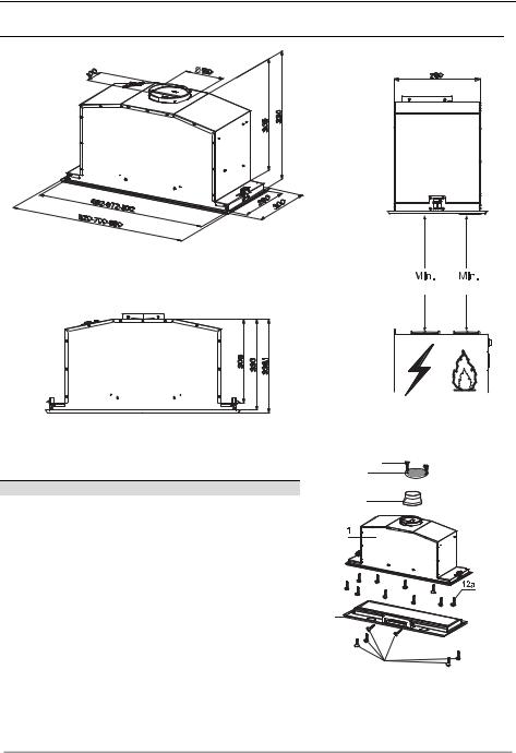
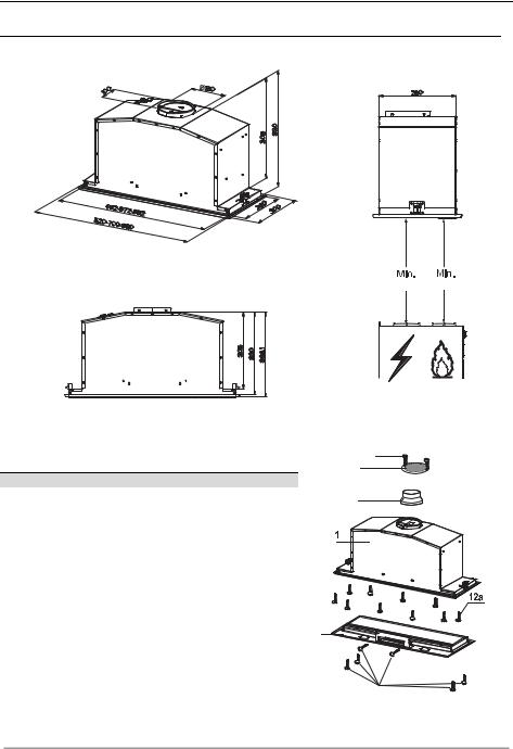
Ingombro
530 mm 530 mm
Componenti
Rif. Q.tà Componenti di Prodotto
11 Corpo Cappa completo di: Comandi, Luce, Filtri, Gruppo Aspiratore.
2 |
1 |
Cornice |
8 |
1 |
Griglia Direzionata |
9 |
1 |
Flangia di riduzione ø 150-120 mm |
Rif. |
Q.tà |
Componenti di Installazione |
12a |
10 |
Viti |
12e |
2 |
Viti 2,9 x 9,5 |
12f |
6 |
Viti 2,9 x 6,5 |
|
Q.tà |
Documentazione |
|
1 |
Libretto Istruzioni |
12e
8
9
2 |
12f
IT |
|
77 |
INSTALLAZIONE
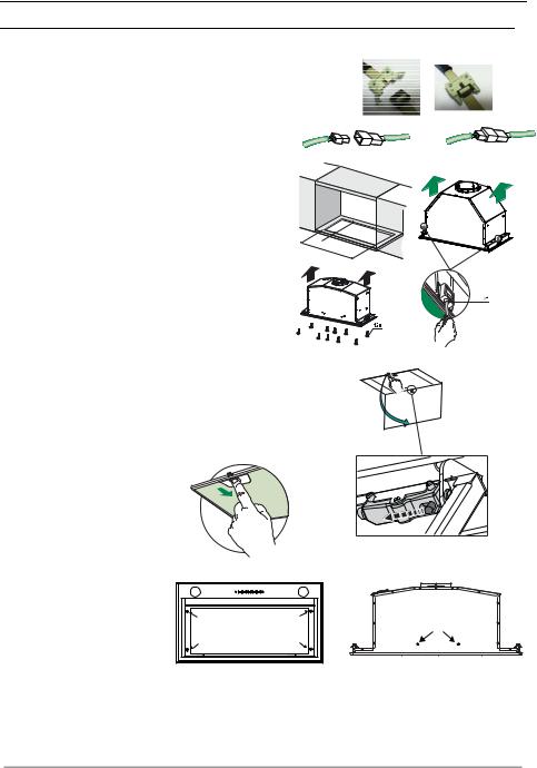
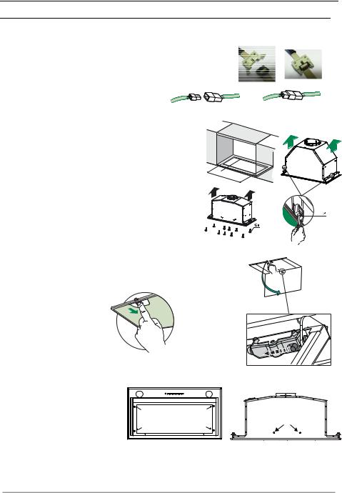
Montaggio Corpo Cappa
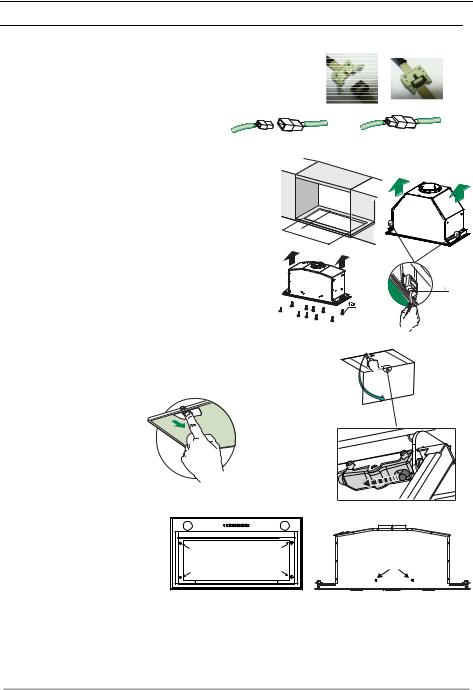
PRIMA DI MONTARE LA CAPPA AL PENSILE AGIRE COME SEGUE:
• Scollegare il Cablaggio dei Comandi agendo sui connettori.
• Scollegare il Cablaggio Luci agendo sui connettori.
•La Cappa può essere installata direttamente sul piano inferiore dei Pensili.
•Praticare un incasso sul piano inferiore del Pensile, come indicato.
•Inserire la Cappa fino ad agganciare i Supporti laterali a scatto.
•Fissare con 10 Viti 12a in dotazione.
•Bloccare definitivamente serrando le Viti Vf dal sotto della Cappa.
|
|
260 |
495 |
13 |
|
- |
|
|
|
675 - |
|
|
|
835 |
•Aprire il pannello aspirante tirandolo.
•Sganciare il pannello dal corpo cappa facendo scorrere l’apposita leva del perno di fissaggio.
• Togliere i filtri Antigrasso.
• Avvitare la Cornice con le 6 Viti 12f, ricollegare il Cablaggio dei Comandi e Luci, rimontare il filtro Antigrasso e il Pannello.
IT |
|
88 |

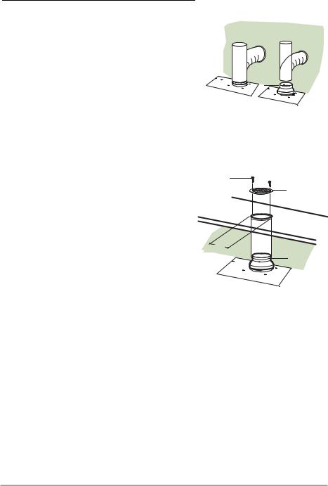
Connessioni
USCITA ARIA VERSIONE ASPIRANTE
Per installazione in Versione Aspirante collegare la Cappa alla tubazione di uscita per mezzo di un tubo rigido o flessibile di ø150 o 120 mm, la cui scelta è lasciata all'installatore.
•Per collegamento con tubo ø120 mm, inserire la Flangia di riduzione 9 sull’Uscita del Corpo Cappa.
•Fissare il tubo con adeguate fascette stringitubo. Il materiale occorrente non è in dotazione.
•Togliere eventuali Filtri Antiodore al Carbone attivo.
USCITA ARIA VERSIONE FILTRANTE
•Praticare un foro ø 125 mm sull’eventuale Mensola soprastante la Cappa.
•Inserire la Flangia di riduzione 9 sull’uscita del Corpo Cappa.
•Collegare la Flangia al foro di uscita sulla Mensola soprastante la Cappa con un tubo rigido o flessibile di ø120 mm.
•Fissare il tubo con adeguate fascette stringitubo. Il materiale occorrente non è in dotazione.
•Fissare la Griglia direzionata 8 sull’uscita con 2 Viti 12e (2,9 x 9,5) in dotazione.
•Assicurarsi della presenza dei Filtri antiodore al Carbone attivo.
ø 150 |
ø 120 |
|
9 |
12e
8
ø 125 |
9 |
|
CONNESSIONE ELETTRICA
•Collegare la Cappa all’Alimentazione di Rete interponendo un Interruttore bipolare con a- pertura dei contatti di almeno 3 mm.
IT |
|
99 |
USO
|
|
|
|
|
|
|
|
L |
|
|
|
|
|
|
|
S1 |
T1 |
|
|
|
|
|
|
|
|
|
|
|
|
|
|
|
|
|
T2 |
L |
T1 |
|
T2 |
|
T3 |
T4 |
|
T3 |
|
|
|
|
|||||
|
S1 |
|
|
|
|
|
|
T4 |
|
|
|
|
|
|
|
|
|
|
|
|
|
|
|
|
|
S1 |
|
L |
T1 |
T2 |
T3 |
T4 |
|
|
|
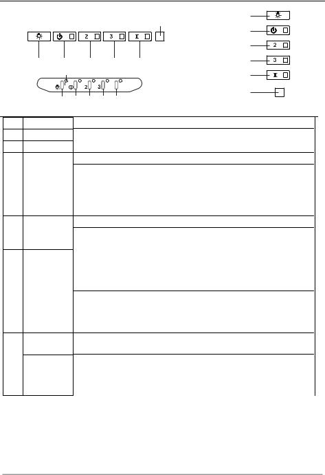
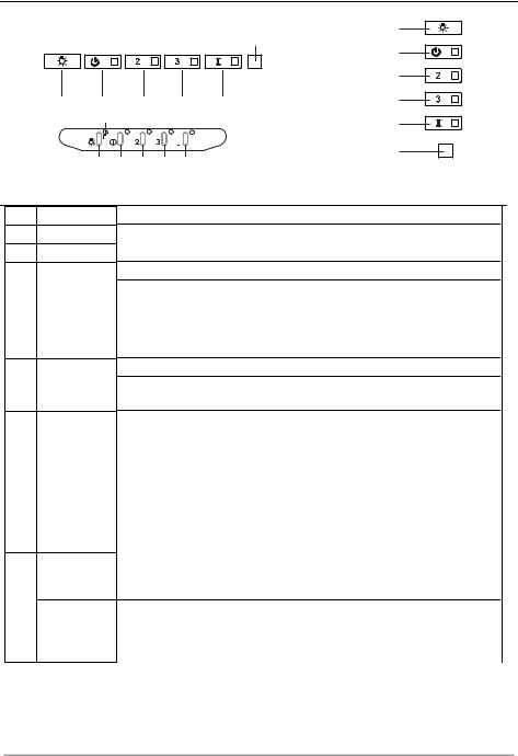
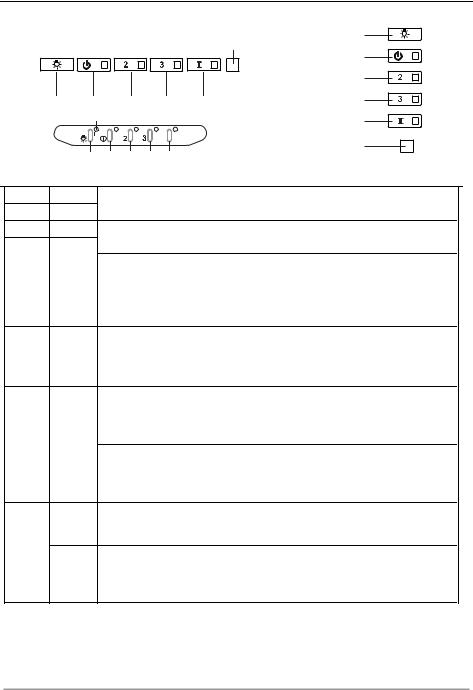
Quadro comandi
Tasto Led
L -
T1 Fisso
T2 Fisso
T3 Fisso
T4 Fisso
S1 Fisso
Lampeggiante
Funzione
Accende/Spegne le luci alla massima luminosità.. Accende/Spegne il motore alla prima velocità. Accende il motore alla seconda velocità.
Tenendo il tasto premuto per circa 5 secondi, quando tutti i carichi sono spenti (Motore+Luce), si attiva l’allarme dei Filtri al Carbone attivo visualizzando un doppio lampeggio del relativo Led.
Per disattivarlo, si preme di nuovo il tasto per altri 5 secondi visualizzando un lampeggio singolo del relativo Led.
Accende il motore alla terza velocità.
Tenendo premuto il tasto per circa 3 secondi, quando tutti i carichi sono spenti (Motore+Luce), si effettua il reset visualizzando il triplo lampeggio del Led S1.
Accende il motore alla velocità INTENSIVA.
Questa velocità è temporizzata a 6 minuti. Terminato il tempo, il sistema ritorna automaticamente alla velocità precedentemente selezionata. Se attivata da motore spento una volta finito il tempo passa alla modalità OFF.
Tenendo premuto per 5 secondi si abilità il telecomando visualizzando un doppio lampeggio del medesimo led.
Tenendo il tasto premuto per 5 secondi si disabilita il telecomando visualizzando il lampeggio del rispettivo led una sola volta.
Segnala l’allarme saturazione Filtri Antigrasso Metallici e la necessità di lavarli. L’allarme entra in funzione dopo 100 ore di lavoro effettivo della Cappa.
Segnala, quando è attivato, l’allarme saturazione Filtro Antiodore al Carbone Attivo, che deve essere sostituito; devono anche essere lavati i Filtri Antigrasso Metallici. L’allarme saturazione Filtro Antiodore al Carbone Attivo entra in funzione dopo 200 ore di lavoro effettivo della Cappa.
IT |
|
1 |
|
10 |
PULIZIA E MANUTENZIONE
TELECOMANDO (OPZIONALE)
Questo apparecchio può essere comandato per mezzo di un telecomando, alimentato con una batteria da 3 V del tipo CR2032 (non inclusa).
•Non riporre il telecomando in prossimità di fonti di calore.
•Non disperdere le pile nell’ambiente, depositarle negli appositi contenitori.
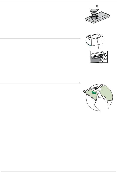
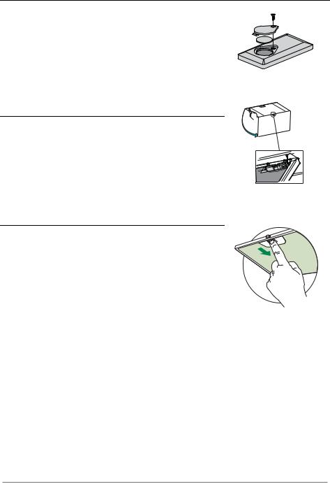
Apertura Pannello
•Aprire il Pannello tirandolo.
•Pulirlo esternamente con un panno umido e detersivo liquido neutro.
•Pulirlo anche internamente utilizzando un panno umido e detergente neutro; non utilizzare panni o spugne bagnate, né getti d’acqua; non utilizzare sostanze abrasive.
Filtri antigrasso metallici
Sono lavabili in lavastoviglie, e necessitano di essere lavati quando il Led S1 si accende o almeno ogni 2 mesi circa di utilizzo o più frequentemente, per un uso particolarmente intenso.
PULIZIA FILTRI
Reset del segnale di allarme
•Spegnere le Luci e il Motore di aspirazione.
•Premere il tasto T3 per almeno 3 secondi, sino al triplo lampeggio di conferma del Led.
Pulizia Filtri
•Aprire le Ante.
•Togliere il Filtro spingendolo verso la parte posteriore del gruppo e tirando contemporaneamente verso il basso.
•Lavare il filtro evitando di piegarlo, e lasciarlo asciugare prima di rimontarlo (un’eventuale cambiamento del colore della superficie del filtro, che potrebbe verificarsi nel tempo, non pregiudica assolutamente l’efficienza dello stesso).
•Rimontarlo facendo attenzione a mantenere la maniglia verso la parte visibile esterna.
•Richiudere le Ante.
IT |
|
1 |
|
11 |
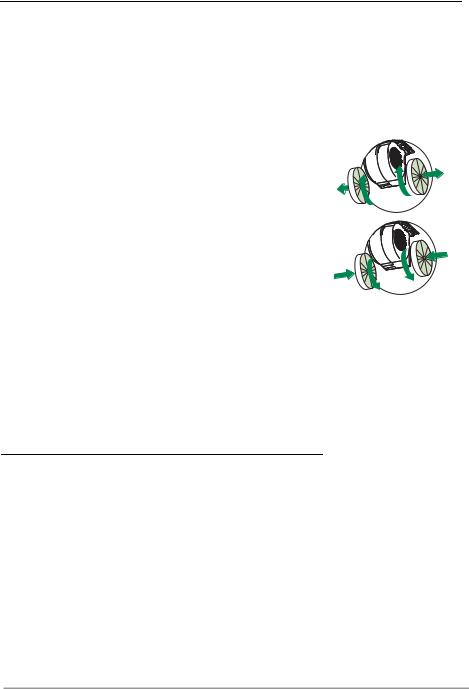
Filtri antiodore al Carbone attivo (Versione Filtrante)
Non è lavabile e non è rigenerabile, va sostituito quando il led S1 lampeggia o almeno ogni 4 mesi. La segnalazione di Allarme, se preventivamente attivata, si verifica solo quando é azionato il Motore di aspirazione.
Attivazione del segnale di allarme
•Nelle Cappe in Versione Filtrante, la segnalazione di Allarme saturazione Filtri va attivata al momento dell’installazione o successivamente.
•Spegnere le Luci e il Motore di aspirazione.
•Premere per 5 secondi il Tasto T2 sino al doppio lampeggio di conferma del Led.
SOSTITUZIONE
Reset del segnale di allarme
•Spegnere le Luci e il Motore di aspirazione.
•Premere il tasto T3 per almeno 3 secondi, sino al triplo lampeggio di conferma del Led.
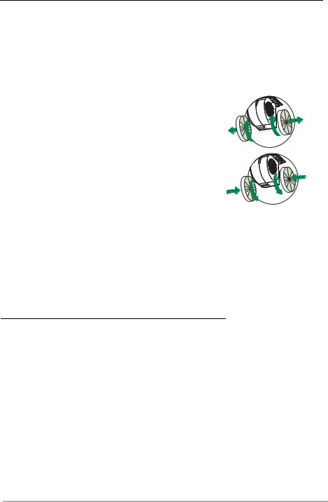
Sostituzione Filtro
•Aprire le Ante.
•Rimuovere il Filtro antigrasso.
•Rimuovere i Filtri antiodore al Carbone attivo saturi, come indicato (A).
•Montare i nuovi Filtri, come indicato (B).
•Rimontare il Filtro antigrasso.
•Chiudere le Ante.
A
B |
Illuminazione
•Per la sostituzione contattare l’Assistenza Tecnica ("Per l'acquisto rivolgersi all'assistenza tecnica").
IT |
|
1 |
|
12 |

SICHERHEITSINFORMATIONEN
 Zu Ihrer eigenen Sicherheit und für die korrekte Funktion des Gerätes lesen Sie bitte diese Betriebsanleitung aufmerksam durch, bevor Sie das Gerät installieren und benutzen. Verwahren Sie die Bedienungsanleitung stets zusammen mit dem Gerät, auch wenn Sie dieses an Dritte weitergeben oder übertragen. Es ist wichtig, dass der Benutzer alle Betriebsund Sicherheitsmerkmale des Gerätes kennt.
 Die Kabel müssen von einem zuständigen Fachmann angeschlossen werden.
Der Hersteller haftet nicht für etwaige Schäden, die durch eine fehlerhafte Installation oder einen ungeeigneten Gebrauch entstehen könnten.
Der min. Sicherheitsabstand zwischen Kochfeld und Abzugshaube beträgt 650 mm (einige Modelle können auch niedriger installiert werden; siehe Absatz Installation).
Sollten die Installationsanweisungen des gasbetriebenen Kochfelds einen größeren Abstand als oben angegeben vorsehen, ist dies zu berücksichtigen.
Sicherstellen, dass die Netzspannung der auf dem Typenschild angegebenen Spannung entspricht. Das Typenschild ist im Inneren der Haube angebracht.
Trennvorrichtungen müssen in der festen Anlage gemäß Normen über Verkabelungssysteme installiert werden.
Für Geräte der Klasse I sicherstellen, dass das Versorgungsnetz des Gebäudes korrekt geerdet ist.
Die Abzugshaube an den Schornstein mit einem Rohr mit Mindestdurchmesser von 120 mm anschließen. Der Verlauf des Rauchabzugs muss so kurz wie möglich sein.
Alle gesetzlichen Vorschriften im Bereich Abluft einhalten.
Die Abzugshaube darf nicht an einen Schacht angeschlossen werden, in den Rauchgase abgeleitet werden (z. B. von Heizkesseln, Kaminen, usw.).
DE |
|
1 |
|
13 |

Falls die Abzugshaube mit Geräten verwendet wird, die nicht elektrisch betrieben sind (z.B. Gasgeräte), muss im Raum für eine ausreichende Belüftung gesorgt werden, damit der Rückfluss der Abgase verhindert wird. Wird die Abzugshaube zusammen mit nicht elektrisch betriebenen Geräten eingesetzt, darf der Unterdruck im Raum 0,04 mbar nicht überschreiten, damit die Abgase nicht wieder angesaugt werden.
Die Luft darf nicht durch einen Kanal abgelassen werden, der als Rauchabzug für Gasgeräte oder Geräte verwendet wird, die mit anderen Brennstoffen betrieben werden.
Wenn das Gerätekabel beschädigt ist, muss es vom Hersteller oder von einem Kundendiensttechniker ersetzt werden.
Den Stecker in eine den einschlägigen Vorschriften entsprechende zugängliche Steckdose stecken.
Was die technischen und sicherheitsrelevanten Maßnahmen für den Rauchabzug betrifft, sind die Vorgaben der örtlichen Behörden streng einzuhalten.
 WARNUNG: Bevor die Haube installiert wird, die Schutzfolien abziehen.Nur für die Abzugshaube geeignete Schrauben und Kleinteile verwenden.
 WARNUNG: Die mangelnde Verwendung von Schrauben und Befestigungselementen gemäß der vorliegenden Anleitung kann zu Stromschlaggefahr führen.
Nicht direkt mit optischen Instrumenten (Fernglas, Lupe, usw.) in das Licht schauen.
Auf keinen Fall unter der Haube flambieren: Dabei könnte ein Brand entstehen.Dieses Gerät darf von Kindern ab 8 Jahren und von Personen mit beschränkten geistigen, physischen oder sensorischen Fähigkeiten oder mangels Erfahrung
und/oder mangels Wissen benutzt werden, vorausgesetzt, sie werden aufmerksam beaufsichtigt oder über den sicheren Gebrauch des Geräts und die damit verbundenen Gefahren eingewiesen. Sicherstellen, dass Kinder nicht mit dem Gerät spielen. Vom Benutzer auszuführende Reinigungsund Wartungsarbeiten dürfen nicht von Kindern ausgeführt werden, sofern sie nicht dabei beaufsichtigt werden.
Kinder müssen beaufsichtigt werden, damit sichergestellt wird, dass sie nicht am Gerät spielen.
DE |
|
1 |
|
14 |

Dieses Gerät darf nicht von Personen (einschließlich Kindern) mit beschränkten geistigen, physischen oder sensorischen Fähigkeiten oder mangels Erfahrung und/oder mangels Wissen benutzt werden, außer sie werden aufmerksam beaufsichtigt und eingewiesen.
 Die frei zugänglichen Teile können während des Kochens mit Kochgeräten sehr heiß werden.
Die Filter sind nach den angegebenen Intervallen zu reinigen und/oder zu ersetzen (Brandgefahr). Siehe Absatz Wartung und Reinigung.
Wenn die Abzugshaube gleichzeitig mit Geräten verwendet wird, die Gas oder andere Brennstoffe benutzen, muss im Raum eine ausreichende Belüftung vorhanden sein (gilt nicht für Geräte, die nur Luft in den Raum ablassen).
Schutzschild bei Rissbildung ersetzen. Das Symbol  am Produkt oder auf der Verpackung weist darauf hin, dass das Gerät nicht als normaler Hausmüll entsorgt werden darf. Das ausrangierte Gerät muss vielmehr bei einer speziellen Sammelstelle für elektrische und elektronische Geräte abgegeben werden. Mit der vorschriftsmäßigen Entsorgung des Gerätes trägt der Benutzer dazu bei, schädliche Auswirkungen auf Umwelt und Gesundheit zu vermeiden. Weitere Informationen zum Recycling dieses Produktes können bei der zuständigen Behörde, der örtlichen Abfallbeseitigung oder bei dem Händler, der das Gerät verkauft hat, eingeholt werden.
DE |
|
1 |
|
15 |
CHARAKTERISTIKEN
Platzbedarf
530 mm 530 mm
Komponenten
Bez. Menge Produktkomponenten
11 Haubenkörper komplett mit: Bedienelemente, Beleuchtung, Filter, Absaugeinheit
2 |
1 |
Rahmen |
8 |
1 |
Luftstromrichtungsgitter |
9 |
1 |
Reduzierflansch ø 150-120 mm |
Bez. |
Menge Produktkomponenten |
|
12a |
10 |
Schrauben |
12e |
2 |
Schrauben 2,9 x 9,5 |
12f |
6 |
Schrauben 2,9 x 6,5 |
|
Menge Unterlagen |
|
|
1 |
Betriebsanleitung |
12e
8
9
2 |
12f
DE |
|
1 |
|
16 |
MONTAGE
Montage des Haubenkörpers
BEVOR DIE HAUBE AM HÄNGESCHRANK MONTIERT WIRD, WIE FOLGT VORGEHEN:
•Die Drähte der Bedienelemente abhängen, indem die Verbinder gelöst werden.
•Die Drähte der Beleuchtung abhängen, indem die
Verbinder gelöst werden.
•Die Haube kann direkt an der Unterseite des Hängeschranks angebracht werden min.
•An der Unterseite des Hängeschranks eine Aussparung anfertigen, wie abgebildet.
•Die Haube einsetzen und die seitlichen Halterungen einhaken.
•Mit den 10 mitgelieferten Schrauben 12a befestigen.
•Durch Festschrauben von unten der Schrauben Vf definitiv blockieren.
 260
260
495 |
13 |
|
- |
|
|
|
675 - |
|
|
|
835 |
•Das Absaugpaneel herausziehen.
•Das Paneel vom Haubenkörper lösen, in dem der spezielle Hebel des Befestigungszapfens verschoben wird.
• Die Fettfilter entfernen.
• Den Rahmen mit den 6 Schrauben 12f wieder befestigen, die Drähte von Bedienelementen und Beleuchtung erneut anschließen, den Fettfilter einbauen und das Paneel wieder verschließen.
DE |
|
1 |
|
17 |

Anschluss im Abluftbetrieb
Bei Abluftbetrieb kann die Haube vom Installateur wahlweise mittels Rohr oder Schlauch (ø 150 oder 120 mm) an die Außenrohrleitung angeschlossen werden.
•Bei Verwendung eines Anschlussrohres ø 120 den Reduzierflansch 9 am Haubenaustritt anbringen.
•Das Rohr mit geeigneten Rohrschellen fixieren. Das hierzu erforderliche Material wird nicht mitgeliefert.
•Eventuell vorhandene Aktivkohlefilter entnehmen.
Anschluss im Umluftbetrieb
•In das eventuell über der Haube vorhandene Bord ein Loch ø 125 mm bohren.
•Den Reduzierflansch 9 am Haubenaustritt anbringen.
•Den Flansch beim Luftaustritt am Bord oberhalb der Haube mittels Rohr oder Schlauch ø120 mm anschließen.
•Das Rohr mit geeigneten Rohrschellen fixieren. Das hierzu erforderliche Material wird nicht mitgeliefert.
•Das Luftleitgitter 8 mit Hilfe von 2 der mitgelieferten Schrauben 12e (2,9 x 9,5) beim Austritt der rückzuführenden Luft fixieren.
•Sicherstellen, dass der Aktivkohle-Geruchsfilter vorhanden ist.
ELEKTROANSCHLUSS
ø 150 |
ø 120 |
|
9 |
12e
8
ø 125 |
9 |
|
•Bei Anschluss der Haube an das Stromnetz muss ein zweipoliger Schalter mit einem Öffnungsweg von mindestens 3 mm zwischengeschaltet werden.
DE |
|
1 |
|
18 |
BEDIENUNG
|
|
|
|
|
|
|
|
L |
|
|
|
|
|
|
|
S1 |
T1 |
|
|
|
|
|
|
|
|
|
|
|
|
|
|
|
|
|
T2 |
L |
T1 |
|
T2 |
|
T3 |
T4 |
|
T3 |
|
|
|
|
|||||
|
S1 |
|
|
|
|
|
|
T4 |
|
|
|
|
|
|
|
|
|
|
|
|
|
|
|
|
|
S1 |
|
L |
T1 |
T2 |
T3 |
T4 |
|
|
|
Schalttafel
Taste LED
L -
T1 Bleibend
T2 Bleibend
T3 Bleibend
T4 Bleibend
S1 Bleibend
Blinkend
Funktion
Schaltet die Beleuchtung bei maximaler Intensität ein/aus. Schaltet den Motor bei der ersten Betriebsgeschwindigkeit ein/aus. Schaltet den Motor bei der zweiten Betriebsgeschwindigkeit ein.
Mit zirka 5 Sekunden langem Gedrückthalten der Taste bei abgeschalteten Verbrauchern (Motor+Licht) wird der Alarm für aktive Aktivkohlefilter aktiviert und die entsprechende LED blinkt zweimal.
Zum Abstellen die Taste erneut 5 Sekunden lang drücken, die entsprechende LED blinkt ein Mal.
Schaltet den Motor bei der dritten Betriebsgeschwindigkeit ein.
Mit zirka 3 Sekunden langem Gedrückthalten der Taste bei abgeschalteten Verbrauchern (Motor+Licht) erfolgt ein Reset und die LED S1 blinkt drei Mal.
Schaltet den Motor bei Intensivgeschwindigkeit ein.
Diese Geschwindigkeit ist auf 6 Minuten zeitgeregelt. Nach Ablauf dieser Zeit kehrt das System zu der zuvor eingestellten Geschwindigkeit zurück. Wird sie bei abgestelltem Motor aktiviert, wird nach Ablauf der Zeit zum Betriebsmodus OFF übergegangen.
Mit 5 Sekunden langem Drücken wird die Fernbedienung aktiviert und die entsprechende LED blinkt zwei Mal.
Mit 5 Sekunden langem Drücken wird die Fernbedienung deaktiviert und die entsprechende LED blinkt nur ein Mal.
Meldet den Alarm für Sättigung der Metallfettfilter und die Notwendigkeit, diese zu waschen. Dieser Alarm wird nach 100 effektiven Betriebsstunden der Abzugshaube ausgelöst.
Meldet, sofern aktiviert, den Alarm für Sättigung des Aktivkohlefilters, der ausgewechselt werden muss; auch die Metallfettfilter müssen gewaschen werden. Der Alarm für Sättigung des Aktivkohlefilters wird nach 200 effektiven Betriebsstunden der Abzugshaube ausgelöst.
DE |
|
1 |
|
19 |
REINIGUNG UND WARTUNG
FERNBEDIENUNG (OPTION)
Dieses Gerät kann per Fernbedienung, die mit einer 3V-Batterie vom Typ CR2032 (nicht mitgeliefert) versorgt wird, bedient werden.
•Die Fernbedienung nicht in der Nähe von Wärmequellen ablegen.
•Altbatterien zum Schutz der Umwelt in Sammelboxen entsorgen.
Öffnen des Paneels
•Das Paneel herausziehen.
•Die Außenflächen mit einem feuchten Lappen und einem neutralen Flüssigreiniger säubern.
•Auch Innen mit einem feuchten Lappen und einem neutralen Reinigungsmittel säubern; keine nassen Tücher oder Schwämme, oder gar Wasser verwenden, und keine schleifenden Mittel einsetzen.
Metallfettfilter
Die Fettfilter sind spülmaschinengeeignet und müssen gewaschen werden, sobald sich die LED S1 einschaltet, oder mindestens alle 2 Monate, oder auch öfter, je nach Intensität des Gebrauchs.
REINIGUNG DER FILTER
Reset des Alarmsignals
•Die Beleuchtung und den Absaugmotor abstellen.
•Die Taste T3 mindestens 3 Sekunden lang drücken, bis der Vorgang durch dreimaliges Blinken der LED bestätigt wird.
Reinigung der Filter
•Die Klappen öffnen.
•Den Filter zu dem hinteren Teil der Gruppe schieben und gleichzeitig nach unten ziehen.
•Den Filter waschen, ohne ihn zu verbiegen, und vor dem Wiedereinbau trocknen lassen (die Farbe der Filteroberfläche kann sich mit der Zeit verändern, was aber die Wirksamkeit keinesfalls beeinträchtigt.)
•Nun den Filter wieder einbauen, so dass der Griff zur Aussenseite zeigt.
•Die Klappen wieder schließen.
DE |
|
2 |
|
20 |
Aktivkohle-Geruchsfilter (Umluftvariante)
Der Aktivkohlefilter ist weder waschbar, noch regenerierbar und muss ausgewechselt werden, wenn die LED S1 blinkt, oder mindestens alle 4 Monate. Die Alarmmeldung, wenn zuvor aktiviert, erfolgt nur, wenn der Absaugmotor zugeschaltet ist.
Aktivierung des Alarmsignals
•Bei der Umluftvariante sollte die Alarmanzeige für die Filtersättigung bei der Erstinbetriebnahme aktiviert werden. Zudem kann sie nachträglich wie folgt aktiviert werden:
•Die Beleuchtung und den Absaugmotor abstellen.
•5 Sekunden lang die Taste T2 drücken, bis die LED zur Bestätigung blinkt:
AUSWECHSELN
Reset des Alarmsignals
•Die Beleuchtung und den Absaugmotor abstellen.
•Die Taste T3 mindestens 3 Sekunden lang drücken, bis der Vorgang durch dreimaliges Blinken der LED bestätigt wird.
Auswechseln des Filters
•Die Klappen öffnen.
•Den Fettfilter ausbauen.
•Die verbrauchten Aktivkohle-Geruchsfilter wie angegeben ausbauen (A).
•Die neuen Filter wie angegeben einbauen (B).
•Den Fettfilter wieder einbauen.
•Die Klappen wieder schließen.
A
B |
Beleuchtung
LED-Strahler
•Für den Austausch der LED-Strahler wenden Sie sich bitte an den Kundendienst.
DE |
|
2 |
|
21 |

SAFETY INFORMATION
 For your safety and correct operation of the appliance, read this manual carefully before installation and use. Always keep these instructions with the appliance even if you move or sell it. Users must fully know the operation and safety features of the appliance.
 The wire connection has to be done by specialized technician.
The manufacturer will not be held liable for any damages resulting from incorrect or improper installation.
The minimum safety distance between the cooker top and the extractor hood is 650 mm (some models can be installed at a lower height, please refer to the paragraphs on working dimensions and installation).
If the instructions for installation for the gas hob specify a greater distance, this must be respected.
Check that the mains voltage corresponds to that indicated on the rating plate fixed to the inside of the hood.
Means for disconnection must be incorporated in the fixed wiring in accordance with the wiring rules.
For Class I appliances, check that the domestic power supply guarantees adequate earthing.
Connect the extractor to the exhaust flue through a pipe of minimum diameter 120 mm. The route of the flue must be as short as possible.
Regulations concerning the discharge of air have to be fulfilled.Do not connect the extractor hood to exhaust ducts carrying
combustion fumes (boilers, fireplaces, etc.).
EN |
|
2 |
|
22 |

If the extractor is used in conjunction with non-electrical appliances (e.g. gas burning appliances), a sufficient degree of aeration must be guaranteed in the room in order to prevent the backflow of exhaust gas. When the cooker hood is used in conjunction with appliances supplied with energy other than electric, the negative pressure in the room must not exceed 0,04 mbar to prevent fumes being drawn back into the room by the cooker hood.
The air must not be discharged into a flue that is used for exhausting fumes from appliances burning gas or other fuels.
If the supply cord is damaged, it must be replaced from the manufacturer or its service agent.
Connect the plug to a socket complying with current regulations, located in an accessible place.
With regards to the technical and safety measures to be adopted for fume discharging it is important to closely follow the regulations provided by the local authorities.
 WARNING: Before installing the Hood, remove the protective films.Use only screws and small parts in support of the hood.
 WARNING: Failure to install the screws or fixing device in accordance with these instructions may result in electrical hazards.
Do not look directly at the light through optical devices (binoculars, magnifying glasses…).
Do not flambè under the range hood; risk of fire.
This appliance can be used by children aged from 8 years and above and persons with reduced physical, sensory or mental capabilities or lack of experience and knowledge if they have been given supervision or instruction concerning use of the appliance in a safe way and understand the hazards involved. Children shall not play with the appliance. Cleaning and user maintenance shall not be made by children without supervision.
Children should be supervised to ensure that they do not play with the appliance.
EN |
|
2 |
|
23 |

The appliance is not to be used by persons (including children) with reduced physical, sensory or mental capabilities, or lack of experience and knowledge, unless they have been given supervision or instruction.
 Accessible parts may become hot when used with cooking appliances.
Clean and/or replace the Filters after the specified time period (Fire hazard). See paragraph Care and Cleaning.
There shall be adequate ventilation of the room when the range hood is used at the same time as appliances burning gas or other fuels (not applicable to appliances that only discharge the air back into the room).
The symbol  on the product or on its packaging indicates that this product may not be treated as household waste. Instead it shall be handed over to the applicable collection point for the recycling of electrical and electronic equipment. By ensuring this product is disposed of correctly, you will help prevent potential negative consequences for the environment and human health, which could otherwise be caused by inappropriate waste handling of this product. For more detailed information about recycling of this product, please contact your local city office, your household waste disposal service or the shop where you purchased the product.
EN |
|
2 |
|
24 |

CHARACTERISTICS
Dimensions
Components
Ref. Q.ty Product Components
11 Hood Body, complete with :Controls, Light, Blower, Filters
2 |
1 |
Frame |
8 |
1 |
Directioned grid |
9 |
1 |
Reducer Flange ø 150-120 mm |
Ref. |
Q.ty |
Installation Components |
12a |
10 |
Screws |
12e |
2 |
Screws 2,9 x 9,5 |
12f |
6 |
Screws 2,9 x 6,5 |
|
Q.ty |
Documentation |
|
1 |
Instruction Manual |
530 mm 530 mm
12e
8
9
2 |
12f
EN |
|
2 |
|
25 |
INSTALLATION
Fitting the Hood canopy
BEFORE FITTING THE HOOD TO THE WALL UNIT, PROCEED AS FOLLOWS:
•Disconnect the wires to the Commands at the connectors.
•Disconnect the wires to the Light at the connectors.
•The Hood can be installed directly on the underside of the wall unit.
•Create an opening in the bottom of the wall unit, as shown.
•Insert the hood until the side supports snap into place.
•Fasten using the 10 screws 12a provided.
•Lock in position by tightening the screws Vf from underneath the hood.
•Open the suction panel by turning the specific knob.
•Disconnect the panel from the hood canopy by sliding the fixing pin lever.
• Remove grease filters.
• Screw the Frame into place using the 6 screws 12f, reconnect the wires to the Commands and Light, replace the metal grease filter and the Panel.
 260
260
495 |
13 |
|
- |
|
|
|
675 - |
|
|
|
835 |
EN |
|
2 |
|
26 |
Connections
DUCTED VERSION AIR EXHAUST SYSTEM
When installing the ducted version, connect the hood to the chimney using either a flexible or rigid pipe ø 150 or 120 mm, the choice of which is left to the installer.
•To install a ø 120 mm air exhaust connection, insert the reducer flange 9 on the hood body outlet.
•Fix the pipe in position using sufficient pipe clamps (not supplied).
•Remove possible charcoal filters.
RECIRCULATION VERSION AIR OUTLET
•Cut a hole ø 125 mm in any shelf that may be positioned over the hood.
•Insert the reducer flange 9 on the hood body outlet.
•Connect the flange to the outlet on the shelf over the hood by using a flexible or rigid pipe ø120 mm.
•Fix the pipe in position using sufficient pipe clamps (not supplied).
•Fix the air outlet grid 8 on the recirculation air outlet by using the 2 screws 12e (2,9 x 9,5) provided.
•Ensure that the activated charcoal filters have been inserted.
ø 150 |
ø 120 |
|
9 |
12e
8
ø 125 |
9 |
|
ELECTRICAL CONNECTION
•Connect the hood to the mains through a two-pole switch having a contact gap of at least 3 mm..
EN |
|
2 |
|
27 |
USE
|
|
|
|
|
|
|
|
L |
|
|
|
|
|
|
|
S1 |
T1 |
|
|
|
|
|
|
|
|
|
|
|
|
|
|
|
|
|
T2 |
L |
T1 |
|
T2 |
|
T3 |
T4 |
|
T3 |
|
|
|
|
|||||
|
S1 |
|
|
|
|
|
|
T4 |
|
|
|
|
|
|
|
|
|
|
|
|
|
|
|
|
|
S1 |
|
L |
T1 |
T2 |
T3 |
T4 |
|
|
|
Control panel
Button Led
L -
T1 Fixed
T2 Fixed
T3 Fixed
T4 Fixed
S1 Fixed
Flashing
Function
Turns the lights on/off at maximum strength. Turns the motor on/off at speed one.
Turns the Motor on at speed two.
Press and hold the button for approximately 3 seconds, with all the loads turned off (Motor and Lights), to turn the Activated Charcoal Filter alarm on. The relevant LED flashes twice to confirm.
To turn the alarm off, press the button again and hold for at least 3 seconds. The relevant LED flashes once.
Turns the Motor on at speed three.
Press and hold the button for approximately 3 seconds, with all the loads turned off (Motor and Lights), to perform a reset of Filter saturation alarm. The LED S1 flashes three times.
Turns the Motor on at INTENSIVE Speed.
This speed is timed to run for 6 minutes. At the end of this time, the system returns automatically to the speed that was set before. If it is activated with the motor turned off, the hood will switch to OFF at the end of the time.
Press and hold for 3 seconds to enable the remote control, indicated by the LED flashing twice.
Press and hold for 3 seconds to disable the remote control, indicated by the LED flashing just once.
Signals the Metal Grease Filter saturation alarm, indicating that it is necessary to wash the filters. The alarm is triggered after the Hood has been in operation for 100 working hours.
When this is activated, it signals the Activated Charcoal Filter saturation alarm, indicating that the filter must be changed; the Metal Grease Filters must also be washed. The Activated Charcoal Filter saturation alarm comes into operation after the Hood has been working for 200 hours.
EN |
|
2 |
|
28 |
CARE AND CLEANING
REMOTE CONTROL (OPTIONAL)
This appliance can be commanded using a remote control, powered by a CR2032 type 3 V battery (not supplied).
•Do not place the remote control near heat sources.
•Do not discard the batteries with normal waste, they must be put into the specific containers.
Opening Panel
•Open the Panel by pulling it.
•Clean the outside with a damp cloth and neutral detergent.
•Clean the inside using a damp cloth and neutral detergent; do not use wet cloths or sponges, or jets of water; do not use abrasive substances.
Metal grease filters
These can be washed in the dishwasher, and need to be cleaned whenever the S1 Led comes on or at least once every 2 months use, or more frequently if use is particularly intensive.
CLEANING THE FILTERS
Resetting the alarm signal
•Turn the Lights and the Suction Motor off.
•Press T3 and hold for at least 3 seconds, until LED flashes three times in confirmation.
Cleaning the Filters
•Open the doors.
•Remove the Filter, pushing it towards the back of the unit and at the same time pulling downward.
•Wash the filter without bending it, and leave it to dry thoroughly before replacing (if the surface of the filter changes colour over time, this will have absolutely no effect on its efficiency).
•Replace, taking care to ensure that the handle faces forwards.
•Close the doors again.
EN |
|
2 |
|
29 |
Activated Charcoal Filter (Recirculation Version)
This cannot be washed or regenerated, and must be changed when led S1 starts to flash, or at least once every 4 months. The Alarm signal, if it has been activated, only appears when the Suction motor is turned on.
Activating the alarm signal
•In Recirculation Version Hoods, the Filter Saturation Alarm must be activated on installation or at a later date.
•Turn the Lights and the Suction Motor off.
•Press button T2 and hold it for 5 seconds until the LED flashes twice in confirmation:
CHANGING
Resetting the alarm signal
•Turn the Lights and the Suction Motor off.
•Press T3 and hold for at least 3 seconds, until LED flashes three times in confirmation.
Changing the Filter
•Open the doors.
•Remove the Metal Grease Filter.
•Remove the saturated Activated Charcoal Filters, as indicated (A).
•Fit the new Filters, as indicated (B).
•Replace the Metal grease filters.
•Close the doors.
A
B |
Lighting unit
•For replacement contact technical support ("To purchase contact technical support").
EN |
|
30 |
 Loading...