How it Works
Log In / Sign Up
Buy Points
How it Works
FAQ
Contact Us
Questions and Suggestions
Users
Bertazzoni
Loading...
K
KU122 PRO 1X
KU24 PRO 1X
KU24PRO1X14
7
KU24PRO1XV
5
KU30 PRO
KU30PRO1X
6
KU30PRO1X14
8
KU30PRO1XV
6
KU36PRO1X
6
KU36PRO1X14
7
KU36PRO1XV
6
KU36 PRO 2X
2
KU36PRO2X14
6
KU48PRO1X
3
KU48PRO1X14
5
KU48 PRO 2X
2
KU48PRO2X14
6
KU60 PRO 1X
KU90 PRO 1X
KU90 PRO 1 X A
2
KU90PRO2XA
KUD40PRO1XA
M
M3W0GTU4X5A
M3Y0GTU4X2A
M3Y0GTU4X5A
M45CAFX
M7S06ZA7X5DUG
M7S0GTU4X2A
2
M7S0GTU4X-2 OR 5-A
M7S0GTU4X5A
2
M93
M93V
MAS100 6 MFE D CR
2
MAS100 6 MFE D NE
2
MAS100 6 MFE D VI
2
MAS100 6 MFE D XE
2
MAS100 6 MFE D XT
2
MAS100 6 MFE T CR T
2
MAS100 6 MFE T NE T
2
MAS100 6 MFE T VI T
2
MAS100 6 MFE T XT
2
MAS120 6G MFE D CR T
2
MAS120 6G MFE D NE T
2
MAS120 6G MFE D VI T
2
MAS120 6G MFE D XT
2
MAS244GASXE
5
MAS244GASXELP
6
MAS304DFMXE
5
MAS304DFMXELP
5
MAS304DFSXT
6
MAS304DFSXTLP
2
MAS304GASXE
4
MAS304GASXELP
MAS30 4 GAS XT
3
MAS304GASXT01
MAS304GASXTLP
4
MAS304INMXE
3
MAS30 4 INS XT
5
MAS36 5 DFM XE
4
MAS365DFMXELP
MAS36 5 DFS XT
4
MAS365DFSXTLP
MAS36 5 GAS XE
2
MAS365GASXELP
2
MAS365GASXT
3
MAS365GASXT01
MAS365GASXTLP
6
MAS486GDFSXT
3
MAS486GDFSXTLP
2
MAS486GGASXT
4
MAS486GGASXT01
MAS486GGASXTLP
3
MAS90 5 GEV S XE
2
MAS90 5 MFE D XE
2
MAS90 5 MFE S XE
2
MAS90 6 MFE D CR T
2
MAS90 6 MFE D NE T
2
MAS90 6 MFE D VI T
2
MAS90 6 MFE D XE
MAS90 6 MFE D XT
2
MAS90 6 MFE S CR T
2
MAS90 6 MFE S NE T
2
MAS90 6 MFE S VI T
2
MAS90 6 MFE S XT
2
MASCS30X
7
MASFD30XT
4
MASFD30XV
8
MASFS30XT
9
MASFS30XV
10
MASHK24BM
MASHK24DW
MASHK30PI
MASHK36REF
MASS030X
5
MASSO30X
8
MAST244GASBIE
5
MAST244GASNEE
2
MAST244GASNEELP
MAST244GASXB
MAST244GASXE
Loading...
Loading...
Nothing found
MAS304DFMXELP
Cleaning tips
1 pgs
37.56 Kb
0
Installation Guide
1 pgs
84.22 Kb
0
Installation Manual
32 pgs
2.16 Mb
0
Installation Manual
1 pgs
124.9 Kb
0
Specifications
2 pgs
309.55 Kb
0
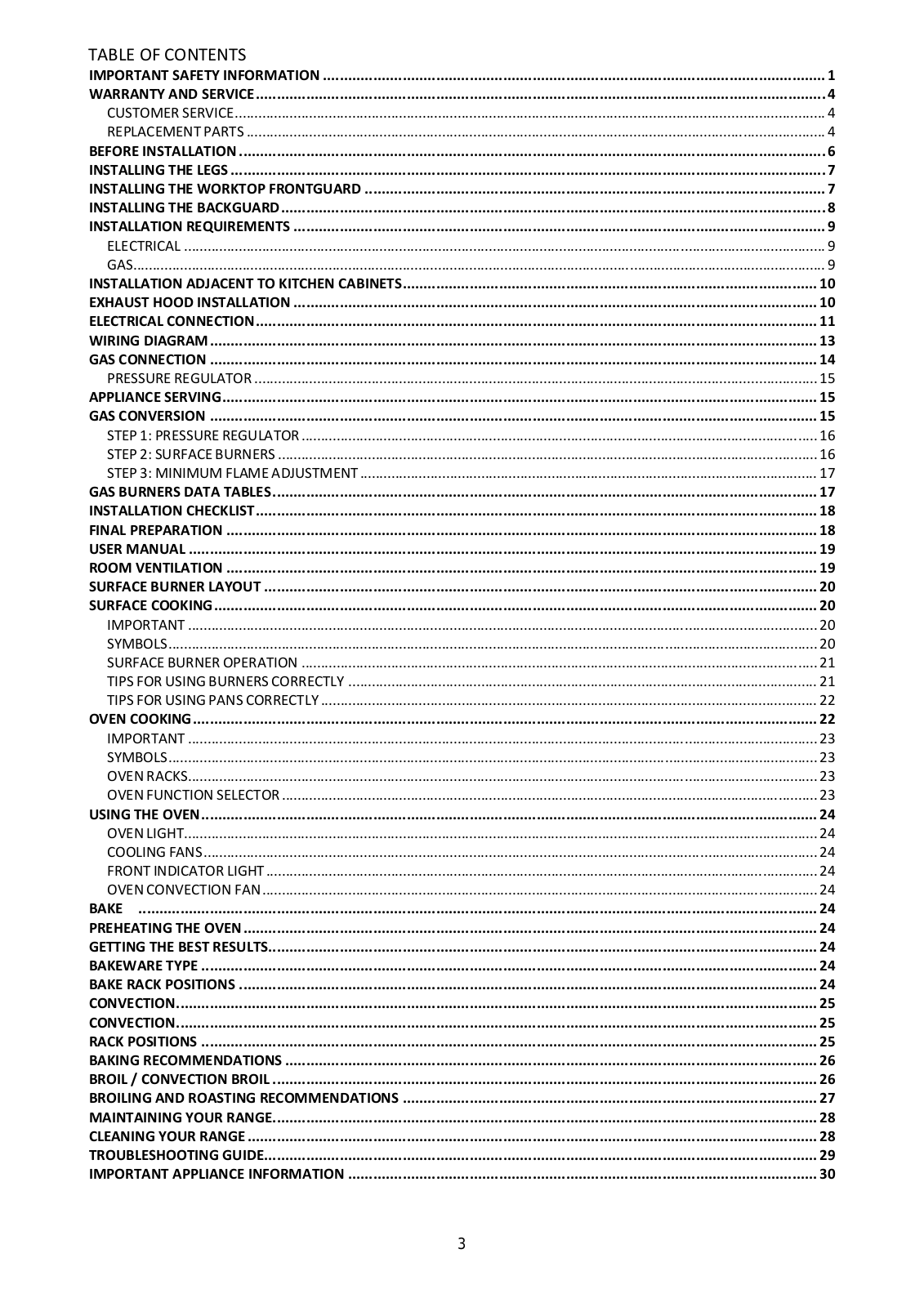
Table of contents
Loading...
Bertazzoni MAS304DFMXELP Installation Manual
...
Bertazzoni Installation Manual
Download
Specifications and Main Features
Frequently Asked Questions
User Manual
Download
Loading...
+
hidden pages
Unhide
You need points to download manuals.
1 point = 1 manual.
You can buy points or you can get point for every manual you upload.
Buy points
Upload your manuals