


BeoLab Transmitter 1
Bang & Olufsen Beolab transmitter 1, 1505, 1506, 1507, 1508 Installation Manual
...
BeoLab Transmitter 1
Type 1505 - 1513
Installation Guide
English - version 1.1
31.0

Introduction 2
Introduction
BeoLab Transmitter 1 is a stand-alone box, that enables existing music systems and TVs to connect wirelessly - within one room - to any Bang &
Olufsen wireless speaker and BeoLab Receiver 1.
BeoLab Transmitter 1 works in the wireless 5 GHz U-NII band frequency spectrum. It is compliant with and will only work with all new Bang &
Olufsen WiSA approved speakers and speakers connected to the BeoLab Receiver 1.
The WiSA technology offers multi-channel wireless sound performance for full surround sound setup. The benets for the Bang & Olufsen
customer are:
- Eliminates cable clutter.
- Offers complete exibility when decorating your room.
- Is an easy add-on to an existing wired setup.
- Delivers high-quality wireless surround sound.
- Offers easy 3rd party integration: mix and match your favourite audio and video components.
The BeoLab Transmitter 1 has four RJ45 inputs with Power Link / Line-in connection which have both a left and right sound channel. This means
you can connect as much as 8 sound channels as input of which one can be a subwoofer in the room. In addition there is an optical stereo
TOSLINK TM input (S/P-DIF) and two RCA (Line-in) for connection stereo sound channels of an audio system.
Despite this the wireless technology used makes it possible to congure up to 11 wireless speakers to the sound channels as desired. One scenario
may be a 7.4 setup.
One switch is used to shift between a Bang & Olufsen Power Link signal in and a line-in signal from a 3rd party product (B&O INPUT YES/NO).
Another switch is used for providing either a pure stereo output in two sound channels only (SUB 2.1 set to OFF) or providing the two stereo sound
channels plus a third sound channel provided by the built in bass management function for the conguration of a wireless subwoofer (SUB 2.1 set
to ON).
Active sources are prioritised in the following order: 1) POWER LINK; 2) TOSLINK; 3) Line-in (via RCA connectors or RJ45 connector).
With the BeoLab Transmitter 1 comes a cable cover for optimised cable management. The BeoLab Transmitter 1 is clicked onto the cable cover and
can be mounted on the wall with the cables directed either up/down or sideways in any direction that is convenient for an elegant installation. The
cable cover becomes an inherent part of the BeoLab Transmitter 1 and lets the solution stand out as one entity.
In a stereo setup, the speakers and the subwoofer must be connected wirelessly.
In a surround sound setup, you can combine wired and wireless speakers as you like.
When the BeoLab 19 has wireless connection the LP FILTER switch is set to OFF. This ensures that the BeoLab 19 emits the frequency pattern sent
to the speaker and also makes the noise pattern audible when conguring the speaker setup.
How to use this installation guide 3
How to use this installation guide
This installation guide gives step by step instructions on how to:
- Mount the product,
- Understand placement rules,
- Connecting and setting up BeoLab Transmitter 1 with products and speakers,
- Use push buttons and understand LED indications,
- Use the ServiceTool and make SW update,
- Understand channel patterns and use worldwide.
Warning
Installation and replacement of parts must be made by Bang & Olufsen
certied installers only.
Navigation in this guide
When the guide is opened, it automatically opens in Full Screen Mode (can be
left as desired - see below). This is primarily done to optimise the usability of
screen reading. There are several ways to navigate when using the guide, see
the survey of keys, shortcuts and hot keys below:
/ (arrow keys on the keyboard) navigates to the next page
/ (arrow keys on the keyboard) navigates to the previous page
Esc
(Esc button ) exits Full Screen Mode (press Ctrl + L to return to
Full Screen Mode).
Another feature to optimise the navigation is the navigation icons at the
bottom of the screen (see below for explanation).
Navigates you to the previous view
Navigates you directly to the start page
Navigates directly to the table of contents (these are active links
- click the link to be directed directly to the associated section)
Prints the document - the print dialogue box opens (Ctrl + P also
brings up this feature)
Navigation TIP
The right side of this page and the Table of Contents, page 30, acts as an active table of contents. Simply click the subject you want and you are
transferred to the section in question.
Introduction
Connecting source system to BeoLab Transmitter 1
Placement of BeoLab Transmitter 1
LED indications
Site survey (Wi-Spy)
Use of USB memory stick
IR-eye - 3rd party product remote control
Always On
Line-in settings and log les
Use of ServiceTool
How to use this installation guide
Setting up and connecting BeoLab Transmitter 1
Push button functions
Combination of Channel pattern and product type No.
Distance between 5 GHz transmitters
Connection specications
BeoLab Transmitter 1 front
BeoLab Transmitter 1 connection panel (rear side)
Demount from wall mounting
Mounting
BeoLab Transmitter 1 front - connection panel 4
BeoLab Transmitter 1 front
The Product Status LED is placed in the front, middle of the BeoLab Transmitter 1; see page 18.
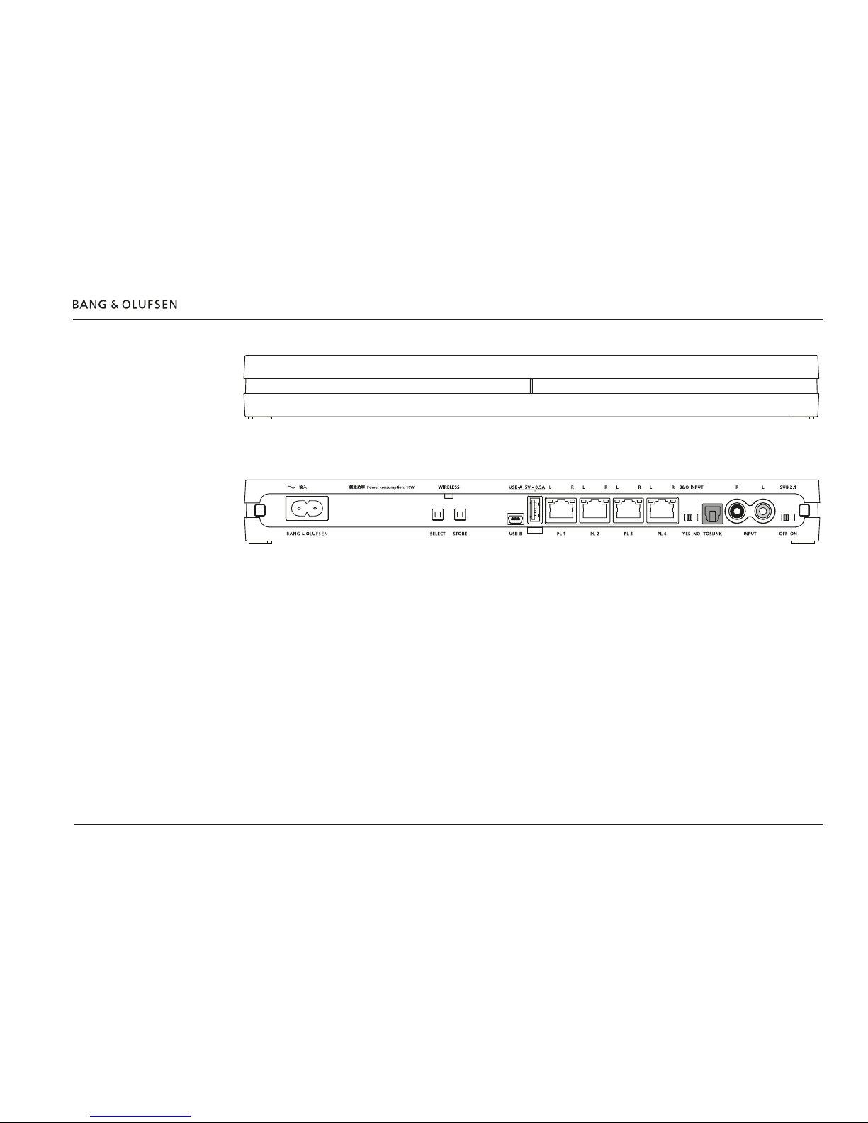
BeoLab Transmitter 1 connection panel (rear side)
The WIRELESS LED is placed in the rear side above the push buttons of the BeoLab Transmitter 1; see LED indications page 18.
The Power Link connectors are used to connect to the source signals.
Above each Power Link input connector two LEDs are placed to give indications regarding the sound channels established to the wireless speakers.
The white LED gives indications regarding the left (L) channel and the red LED gives indications regarding the right (R) channel; see LED indications
page 18.
The Wireless Power Link antennas are placed in the lid (top) of the BeoLab Transmitter 1, and due to the PCBs placed below this, the signal
strength is somewhat attenuated on the backside of the BeoLab Transmitter 1.
It is recommended to place the BeoLab Transmitter 1, so it is not hidden, and it must never be placed behind the TV as the metal parts will prevent
the wireless signals to reach the speakers.
The push buttons can be activated as follows; see also description of push button functions page 17:
- short press ≤1.5 s
- long press ≥ 1.5 s and ≤10 s (often conrmed when the LED turns solid)
- very long press ≥ 10 s
100 - 240V 50/60Hz
Mounting 5
Mounting
The BeoLab Transmitter 1 can be mounted in various ways:
- On a shelf or similar horizontal surface.
- Wall mounted.
Note: Product Status LED on front of BeoLab Transmitter 1, and WIRELESS LED on the rear side.
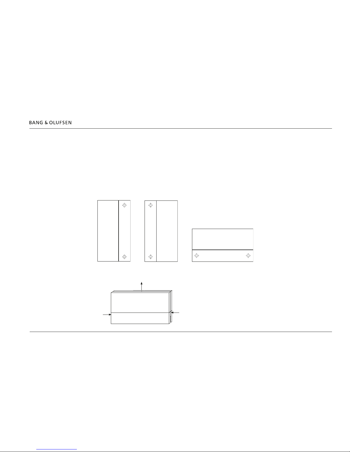
Wall mounting
The BeoLab Transmitter 1 can be mounted on a wall by using the cable cover as wall bracket.
Two screws are placed with a distance of 260 mm/ 10.6”.
See also the setting-up guide enclosed in the packaging for the BeoLab Transmitter 1.
The BeoLab Transmitter 1 can be placed vertically or horizontally. The cable cover is naturally used for organizing the cables.
See example in the below illustrations. (The holes for mounting shown are placed on the back side of the BeoLab Transmitter 1).
Demount from wall mounting
The BeoLab Transmitter 1 is demounted from the cable cover by releasing the two snap-locks , followed by moving the transmitter away from
the cable cover .
Placement of the Beolab Transmitter 1 6
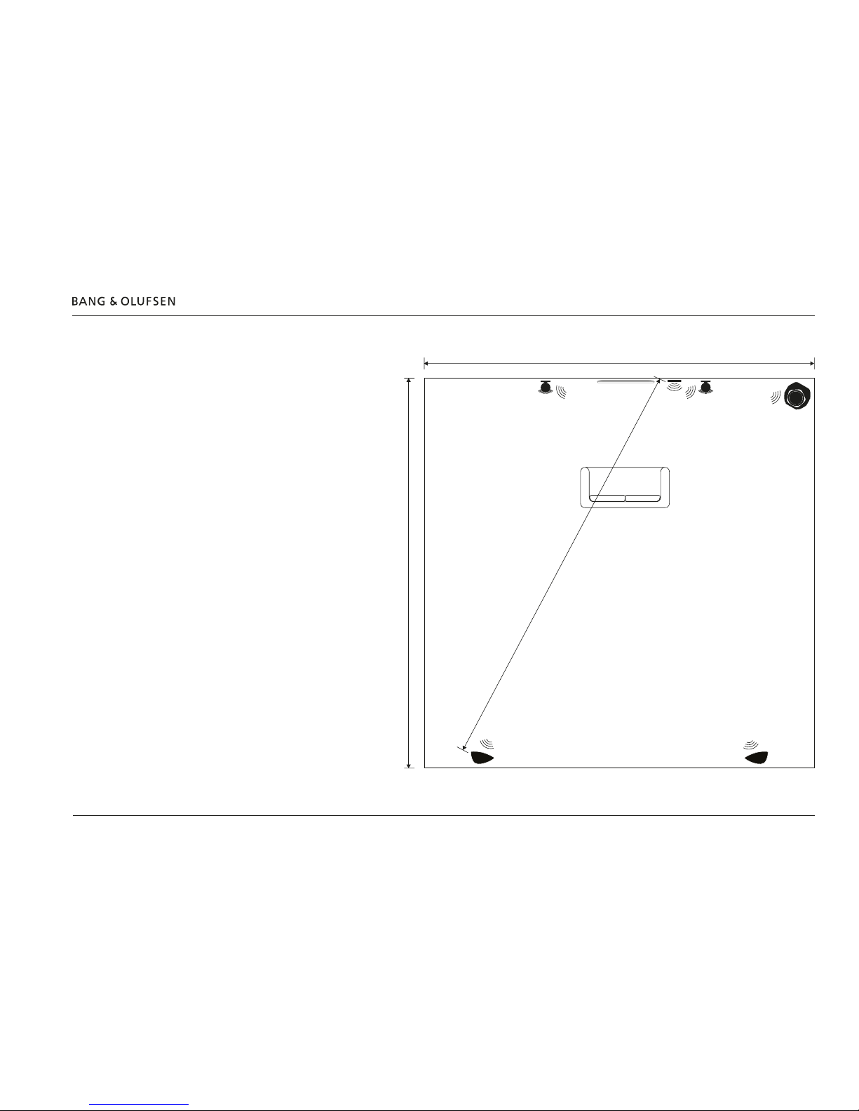
Placement of BeoLab Transmitter 1
The BeoLab Transmitter 1 has an
omnidirectional transmission
characteristic, although this can not
be an ideal sphere.
The transmitter and the receivers of
the loudspeakers must have line-ofsight.
The transmitter and the speakers are
placed inside an area that is
recommended to have the maximum
measurements of 9 × 9m / 30 ×
30ft.
The distance between the BeoLab
Transmitter 1 and any receiver must
not exceed 12 m / 40 ft.
Ideally there must be placed no
objects between the BeoLab
Transmitter 1 and the speakers especially not objects consisting of
material that will block or totally
reect the wireless signals.
Setting listening distance to speakers
In most TVs the listening distance to
each speaker can be set to obtain
true-time listening from all speakers.
If the speaker setup consists of a
mixture of wired and wireless
connected speakers, the distance to
the wireless speakers must be added
6 ms (milliseconds) matching 2 m /
6.7 ft to the actual distance between
the listening position and each
speaker connected wirelessly due to the sound delay handling.
Alternatively the time or distance can be subtracted from the wired speaker setup.
9 m / 30 ft
9 m / 30 ft
maximum 12 m / 40 ft
Connecting source systems to BeoLab Transmitter 1 7
Connecting source system to BeoLab Transmitter 1
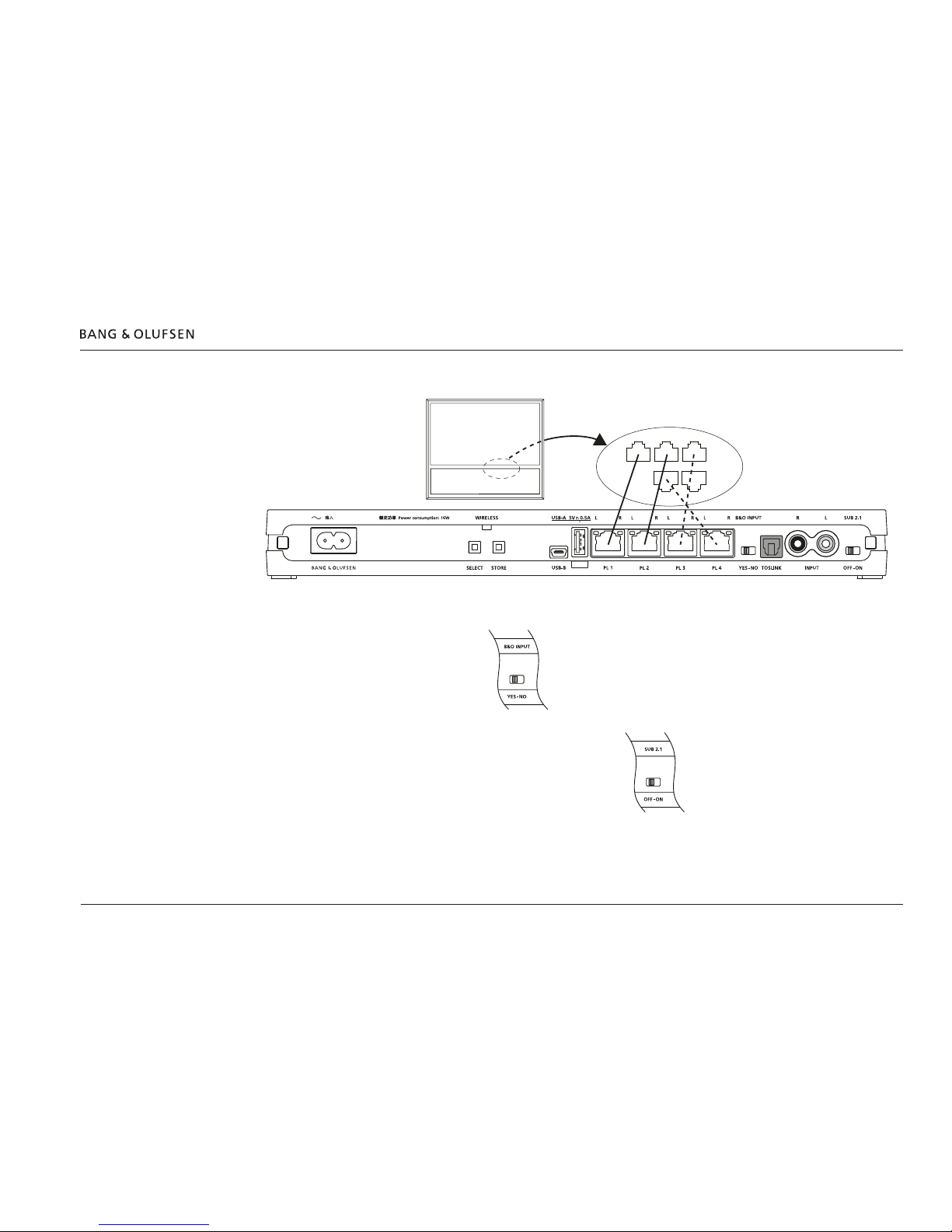
Bang & Olufsen product - Power Link
Connect Bang & Olufsen products to the BeoLab Transmitter 1 using Power Link cables. See more examples page 14.
B&O INPUT
Remember to set the B&O INPUT switch to YES.
SU B 2.1
With Bang & Olufsen video sources set the SUB 2.1 switch to OFF.
With a stereo only signal as input and a wireless subwoofer available,
set the SUB 2.1 switch to ON. The bass management function of the
BeoLab Transmitter 1 provides the subwoofer signal to a wireless subwoofer
indicated as the third sound channel (PL 2 L).
The cut-off frequency for the Bass management is 120Hz.
See the guide for BeoLab Transmitter 1 for variety in connections depending on type of BeoVision and setting the SUB 2.1 switch with the various
speaker combinations.
100 - 240V 50/60Hz
PL 1PL 2PL 3
PL 4
PL 5
Video or
Audio product
Connecting source systems to BeoLab Transmitter 1 8
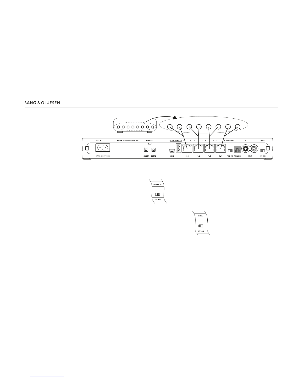
3rd party product using Power Link as Line-in
A wireless 7.1 setup is shown as example in the above illustration.
Connect 3rd party products to the BeoLab Transmitter 1 using Power Link cables.
The volume of the signal must be adjusted from the source system.
B&O INPUT
Remember to set the B&O INPUT switch to NO.
SU B 2.1
With a multiple sounc channel as input set the SUB 2.1 switch to OFF.
With a stereo only signal as input and a wireless subwoofer available,
set the SUB 2.1 switch to ON. The bass management function of the
BeoLab Transmitter 1 provides the subwoofer signal to a wireless subwoofer
indicated as the third sound channel (PL 2 L).
The cut-off frequency for the Bass management is 120Hz.
See the guide for BeoLab Transmitter 1 for variety in speaker combinations.
100 - 240V 50/60Hz
Surround Sound Decoder
FL FR RL RR CS SWCL CR
Connecting source systems to BeoLab Transmitter 1 9
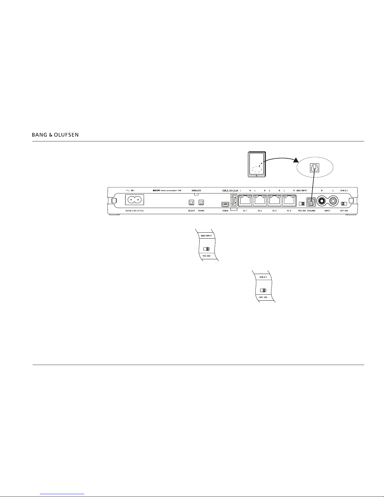
3rd party product using TOSLINK (S/P- DIF)
Connect 3rd party products to the BeoLab Transmitter 1 using a TOSLINK cable. The volume of the signal must be adjusted from the audio system.
B&O INPUT
Remember to set the B&O INPUT switch to NO.
In case a Bang & Olufsen product is connected
additional to the 3rd party product the switch is
set to YES.
SU B 2.1
With a stereo only signal as input and a wireless subwoofer available,
set the SUB 2.1 switch to ON. The bass management function of the
BeoLab Transmitter 1 provides the subwoofer signal to a wireless subwoofer
indicated as the third sound channel (PL 2 L).
The cut-off frequency for the Bass management is 120Hz.
See the guide for BeoLab Transmitter 1 for variety in speaker combinations.
100 - 240V 50/60Hz
TOSLINK
Out
Audio
product
 Loading...