


 Loading...
BeoLab 4
Type 6650, 6652
Service Manual
English
German, French, Italian, Spanish, Danish, Dutch and Japanese versions are available in the Retail System
This Service Manual must be returned with the defective parts/back-up suitcase !
CONTENTS |
|
Survey of modules ...................................................................... |
1.1 |
How to service ......................................................................... |
1.2 |
Warnings – Insulating test ........................................................ |
2.1 |
Adjustments ............................................................................ |
3.1 |
Repair tips ................................................................................ |
4.1 |
Disassembly ............................................................................. |
5.1 |
Specification guidelines for service use ..................................... |
6.1 |
Block diagram ........................................................................... |
7.1 |
Wiring diagram ........................................................................ |
7.2 |
Available parts ......................................................................... |
8.1 |
Survey of modules |
1.1 |
|
|
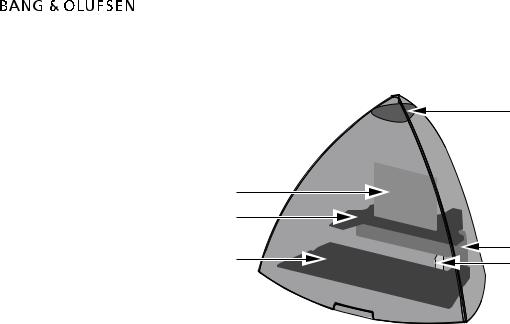
Survey of modules
4
1
2
3 |
5 |
6 |
PCB1 Amplifier
PCB2 SMPS
PCB3 Filter
PCB4 LED
PCB5 Switch
PCB6 Input

1.2 How to service
How to service
Front line service
BeoLab 4 is to be serviced in the customer’s home when it comes to electrical symptoms or exchange of mechanical parts. In this way you avoid having to make more than one visit and using minimum of time on the case, all for the benefit of the customer.
BeoLab 4 has been split-up into as few service items as possible. Each service friendly item is packed individually, prepared for worldwide transport, and has a separate seven digit spare part number to be found in the Bang & Olufsen Retail System or the Service Manual. The exploded view drawing will show the service spare parts.
Back-up suitcase
A back-up suitcase contains all necessary electrical modules for front-line repair of one loudspeaker. Cabinet parts must be ordered separately in the Retail System or directly from B&O Struer DK.
The replaced modules must be returned for repair at Bang & Olufsen, Module Repair Department. Use the Module Repair form or the form in the Retail Order System, Exchange Module.
Delivery
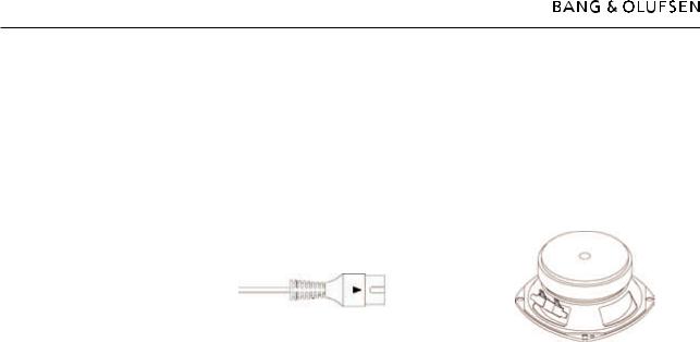
As there is only one type number for BeoLab 4, the product can be used for all markets with 100 to 240 Vac mains voltage. When you order BeoLab 4 (set of two) this includes two mains cables, two Power Link cables and two boxes with the three front covers in the chosen colour. This means that the delivery will consist of four boxes.
This setup allows our packaging department to pack the specific order for the customer no matter which country it goes to or the colour chosen.
Installation and setting-up
Only the switch for loudspeaker placement and the switch for Left or Right - Line or PC must be set into correct position as described in the User Guide before Power Link/Line signal and AC power wires are connected. If the Power Link is used, the switch is for Left or Right setting. If Line connection is used (via mini-jack plug) the switch is for Line (0 to 1V) or PC-line (0 to 2V) setting. See more details in the User Guide. The automatic switch-off circuit is only active with the switch in Line position, and is not active with the switch in PC-line position.
The LED will indicate on (green) or off (red) only.
Fault Finding
Before troubleshooting is initiated, let the customer demonstrate the fault, if possible. There are four electrical modules in the product, and furthermore two additional modules. One with a LED and one with a mini jack socket. Therefore a faulty module is easy to point out in most cases. The PCB’s has been divided into the functionality: Inputs, Amplifier, Power supply and Filter.
No special service programs are available in this product or via the ServiceTool. If there is a fault in the SMPS (PCB2) or Amplifier (PCB1) the LED is typically off.
Only the tweeter unit is protected by a circuit that measures the resistance in the coil, and will automatically turn down the signal level for the tweeter shortly if it is too high for a period.

How to service 1.3
Replacement
Replacement of a loudspeaker unit or the amplifier.
Each loudspeaker is individually adjusted from production to secure optimal stereo perspective.
If a defective loudspeaker unit must be replaced, it is easily done without adjustment due to the specifications of the unit.
Mechanics
All cabinet parts as e.g. the socket panel can be changed on-site. All surfaces can be cleaned with a mild detergent.
Internal parts are supplied as service kits, e.g. the loudspeakers, PCB’s etc.
A product cover (soft) for service, black, can be ordered for transport of BeoLab 4.

2.1Warnings – Insulating test
Warnings
ESD
STATIC ELECTRICITY
MAY DESTROY THE
PRODUCT
When electrical replacements or disassembly is taking place, use an ESD-mat. The internal electronics are very sensitive to static electricity.
Handling
Wear cotton gloves to avoid any fingerprints on the product.
The surfaces on the product are very sensitive, so handling should be done with great care to avoid damage.
Cleaning of the speaker surfaces should only be done with a lint-free cloth which you have dipped in lukewarm water and wrung firmly.
Insulation test
The product must be insulation tested after having been dismantled. Make the test when the set has been reassembled and is ready to be returned to the customer. Flashover must not occur during the test.
Make the insulation test as follows:
Short-circuit the two pins of the mains plug and connect them to one of the terminals of the insulation tester.
Connect the other terminal to ground on the Power Link socket.
NOTE!
To avoid damaging the product it is essential that both terminals of the insulation tester have good contact.
During the test the current must not exceed 5 mA.
Slowly increase the voltage on the insulation tester until a voltage of 2.5 kV (ac) is obtained. Maintain the voltage level for one second, then slowly decrease the voltage to 0 V (ac).

Adjustments 3.1
Adjustments
Adjustments after replacing PCB3 or PCB5
Read out the adjustment position of the old potentiometers, VR601 & VR701, and set the new potentiometers to the same position.
PCB3 – VR601
VR601 
PCB5 – VR701
VR701
4.1Repair tips
Repair tips
Hum in loudspeaker when no music is played.
The Power Link cable must be of type MK III or higher.
The ground connection in Power Link cable lower than MK III may be insufficient for optimum sound performance.
The loudspeaker units can be checked by an ohm-meter (tweeter 5.7Ω ±10%; woofer 6.7Ω ±10%).
Power Link
MK III
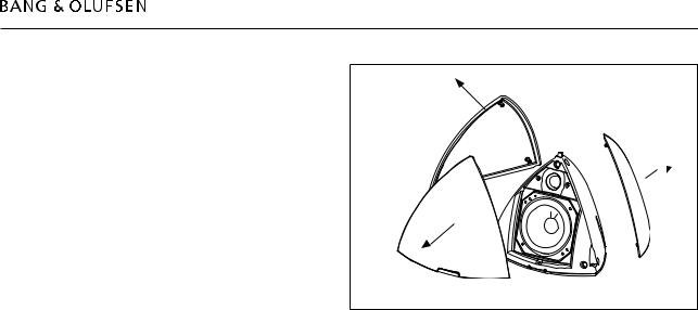
Disassembly 5.1
Remove front cover
- Pull off front covers
Loading...