


 Loading...
PRIME Z390-A
Motherboard

E15017
Revised Edition V2
November 2018
Copyright © 2018 ASUSTeK COMPUTER INC. All Rights Reserved.
No part of this manual, including the products and software described in it, may be reproduced, transmitted, transcribed, stored in a retrieval system, or translated into any language in any form or by any means, except documentation kept by the purchaser for backup purposes, without the express written permission of ASUSTeK COMPUTER INC. (“ASUS”).
Product warranty or service will not be extended if: (1) the product is repaired, modified or altered, unless such repair, modification of alteration is authorized in writing by ASUS; or (2) the serial number of the product is defaced or missing.
ASUS PROVIDES THIS MANUAL “AS IS” WITHOUT WARRANTY OF ANY KIND, EITHER EXPRESS OR IMPLIED, INCLUDING BUT NOT LIMITED TO THE IMPLIED WARRANTIES OR CONDITIONS OF MERCHANTABILITY OR FITNESS FOR A PARTICULAR PURPOSE. IN NO EVENT SHALL ASUS, ITS DIRECTORS, OFFICERS, EMPLOYEES OR AGENTS BE LIABLE FOR ANY INDIRECT, SPECIAL, INCIDENTAL, OR CONSEQUENTIAL DAMAGES (INCLUDING DAMAGES FOR LOSS OF PROFITS, LOSS OF BUSINESS, LOSS OF USE OR DATA, INTERRUPTION OF BUSINESS AND THE LIKE), EVEN IF ASUS HAS BEEN ADVISED OF THE POSSIBILITY OF SUCH DAMAGES ARISING FROM ANY DEFECT OR ERROR IN THIS MANUAL OR PRODUCT.
SPECIFICATIONS AND INFORMATION CONTAINED IN THIS MANUAL ARE FURNISHED FOR INFORMATIONAL USE ONLY, AND ARE SUBJECT TO CHANGE AT ANY TIME WITHOUT NOTICE, AND SHOULD NOT BE CONSTRUED AS A COMMITMENT BY ASUS. ASUS ASSUMES NO RESPONSIBILITY OR LIABILITY FOR ANY ERRORS OR INACCURACIES THAT MAY APPEAR IN THIS MANUAL, INCLUDING THE PRODUCTS AND SOFTWARE DESCRIBED IN IT.
Products and corporate names appearing in this manual may or may not be registered trademarks or copyrights of their respective companies, and are used only for identification or explanation and to the owners’ benefit, without intent to infringe.
Offer to Provide Source Code of Certain Software
This product contains copyrighted software that is licensed under the General Public License (“GPL”), under the Lesser General Public License Version (“LGPL”) and/or other Free Open Source Software Licenses. Such software in this product is distributed without any warranty to the extent permitted by the applicable law. Copies of these licenses are included in this product.
Where the applicable license entitles you to the source code of such software and/or other additional data, you may obtain it for a period of three years after our last shipment of the product, either
(1)for free by downloading it from https://www.asus.com/support/
or
(2)for the cost of reproduction and shipment, which is dependent on the preferred carrier and the location where you want to have it shipped to, by sending a request to:
ASUSTeK Computer Inc.
Legal Compliance Dept.
15 Li Te Rd.,
Beitou, Taipei 112
Taiwan
In your request please provide the name, model number and version, as stated in the About Box of the product for which you wish to obtain the corresponding source code and your contact details so that we can coordinate the terms and cost of shipment with you.
The source code will be distributed WITHOUT ANY WARRANTY and licensed under the same license as the corresponding binary/object code.
This offer is valid to anyone in receipt of this information.
ASUSTeK is eager to duly provide complete source code as required under various Free Open Source Software licenses. If however you encounter any problems in obtaining the full corresponding source code we would be much obliged if you give us a notification to the email address gpl@asus.com, stating the product and describing the problem (please DO NOT send large attachments such as source code archives, etc. to this email address).
ii

Contents
Safety information...................................................................................................... |
vi |
About this guide......................................................................................................... |
vii |
PRIME Z390-A specifications summary.................................................................... |
ix |
Package contents..................................................................................................... |
xiv |
Installation tools and components........................................................................... |
xv |
Chapter 1: |
Product Introduction |
|
|
1.1 |
Motherboard overview............................................................................... |
1-1 |
|
|
1.1.1 |
Before you proceed..................................................................... |
1-1 |
|
1.1.2 |
Motherboard layout...................................................................... |
1-2 |
|
1.1.3 |
Central Processing Unit (CPU).................................................... |
1-4 |
|
1.1.4 |
System memory........................................................................... |
1-5 |
|
1.1.5 |
Expansion slots............................................................................ |
1-7 |
|
1.1.6 |
Onboard buttons and switches.................................................... |
1-9 |
|
1.1.7 |
Jumper....................................................................................... |
1-11 |
|
1.1.8 |
Onboard LEDs........................................................................... |
1-13 |
|
1.1.9 |
Internal connectors.................................................................... |
1-14 |
Chapter 2: |
Basic Installation |
|
|
2.1 |
Building your PC system........................................................................... |
2-1 |
|
|
2.1.1 |
CPU installation........................................................................... |
2-1 |
|
2.1.2 |
Cooling system installation.......................................................... |
2-2 |
|
2.1.3 |
Motherboard installation.............................................................. |
2-5 |
|
2.1.4 |
DIMM installation......................................................................... |
2-6 |
|
2.1.5 |
ATX power connection................................................................. |
2-7 |
|
2.1.6 |
SATA device connection.............................................................. |
2-8 |
|
2.1.7 |
Front I/O connector...................................................................... |
2-9 |
|
2.1.8 |
Expansion card installation........................................................ |
2-10 |
|
2.1.9 |
M.2 installation........................................................................... |
2-13 |
|
2.1.10 |
ASUS fan holder installation...................................................... |
2-14 |
2.2 |
Motherboard rear and audio connections.............................................. |
2-15 |
|
|
2.2.1 |
Rear I/O connection................................................................... |
2-15 |
|
2.2.2 |
Audio I/O connections................................................................ |
2-17 |
2.3 |
Starting up for the first time.................................................................... |
2-19 |
|
2.4 |
Turning off the computer......................................................................... |
2-19 |
|
iii

Chapter 3: |
BIOS Setup |
|
|
3.1 |
Knowing BIOS............................................................................................. |
3-1 |
|
3.2 |
BIOS setup program................................................................................... |
3-2 |
|
|
3.2.1 |
EZ Mode...................................................................................... |
3-3 |
|
3.2.1 |
Advanced Mode........................................................................... |
3-4 |
|
3.2.3 |
QFan Control............................................................................... |
3-8 |
|
3.2.4 |
AI OC Guide.............................................................................. |
3-10 |
|
3.2.5 |
EZ Tuning Wizard...................................................................... |
3-11 |
3.3 |
My Favorites.............................................................................................. |
3-13 |
|
3.4 |
Main menu................................................................................................. |
3-15 |
|
3.5 |
Ai Tweaker menu...................................................................................... |
3-15 |
|
3.6 |
Advanced menu........................................................................................ |
3-17 |
|
|
3.6.1 |
Platform Misc Configuration....................................................... |
3-17 |
|
3.6.2 |
CPU Configuration..................................................................... |
3-17 |
|
3.6.3 |
System Agent (SA) Configuration.............................................. |
3-17 |
|
3.6.4 |
PCH Configuration..................................................................... |
3-18 |
|
3.6.5 |
PCH Storage Configuration....................................................... |
3-18 |
|
3.6.6 |
PCH-FW Configuration.............................................................. |
3-19 |
|
3.6.7 |
Thunderbolt(TM) Configuration.................................................. |
3-19 |
|
3.6.8 |
Onboard Devices Configuration................................................. |
3-19 |
|
3.6.9 |
APM Configuration..................................................................... |
3-20 |
|
3.6.10 |
PCI Subsystem Settings............................................................ |
3-20 |
|
3.6.11 |
USB Configuration..................................................................... |
3-20 |
|
3.6.12 |
Network Stack Configuration..................................................... |
3-20 |
|
3.6.13 |
NVMe Configuration.................................................................. |
3-20 |
|
3.6.14 |
HDD/SSD SMART Information.................................................. |
3-20 |
3.7 |
Monitor menu............................................................................................ |
3-21 |
|
3.8 |
Boot menu................................................................................................. |
3-21 |
|
3.9 |
Tool menu.................................................................................................. |
3-23 |
|
|
3.9.1 |
ASUS EZ Flash 3 Utility............................................................. |
3-23 |
|
3.9.2 |
Secure Erase............................................................................. |
3-24 |
|
3.9.3 |
ASUS User Profile..................................................................... |
3-25 |
|
3.9.4 |
ASUS SPD Information.............................................................. |
3-25 |
|
3.9.5 |
Graphics Card Information......................................................... |
3-25 |
3.10 |
Exit menu................................................................................................... |
3-26 |
|
3.11 |
Updating BIOS.......................................................................................... |
3-27 |
|
|
3.11.1 |
EZ Update.................................................................................. |
3-27 |
|
3.11.2 |
ASUS EZ Flash 3....................................................................... |
3-28 |
|
3.11.3 |
ASUS CrashFree BIOS 3.......................................................... |
3-30 |
iv

Chapter 4: |
RAID Support |
|
|
4.1 |
RAID configurations................................................................................... |
4-1 |
|
|
4.1.1 |
RAID definitions........................................................................... |
4-1 |
Appendix |
|
|
|
Notices |
..................................................................................................................... |
|
A-1 |
ASUS contact information...................................................................................... |
A-5 |
||
v

Safety information
Electrical safety
•To prevent electrical shock hazard, disconnect the power cable from the electrical outlet before relocating the system.
•When adding or removing devices to or from the system, ensure that the power cables for the devices are unplugged before the signal cables are connected. If possible, disconnect all power cables from the existing system before you add a device.
•Before connecting or removing signal cables from the motherboard, ensure that all power cables are unplugged.
•Seek professional assistance before using an adapter or extension cord. These devices could interrupt the grounding circuit.
•Ensure that your power supply is set to the correct voltage in your area. If you are not sure about the voltage of the electrical outlet you are using, contact your local power company.
•If the power supply is broken, do not try to fix it by yourself. Contact a qualified service technician or your retailer.
Operation safety
•Before installing the motherboard and adding devices on it, carefully read all the manuals that came with the package.
•Before using the product, ensure all cables are correctly connected and the power cables are not damaged. If you detect any damage, contact your dealer immediately.
•To avoid short circuits, keep paper clips, screws, and staples away from connectors, slots, sockets and circuitry.
•Avoid dust, humidity, and temperature extremes. Do not place the product in any area where it may become wet.
•Place the product on a stable surface.
•If you encounter technical problems with the product, contact a qualified service technician or your retailer.
•Your motherboard should only be used in environments with ambient temperatures between 0°C and 40°C.
vi

About this guide
This user guide contains the information you need when installing and configuring the motherboard.
How this guide is organized
This guide contains the following parts:
•Chapter 1: Product Introduction
This chapter describes the features of the motherboard and the new technology it supports. It includes description of the switches, jumpers, and connectors on the motherboard.
•Chapter 2: Basic Installation
This chapter lists the hardware setup procedures that you have to perform when installing system components.
•Chapter 3: BIOS Setup
This chapter tells how to change system settings through the BIOS Setup menus. Detailed descriptions of the BIOS parameters are also provided.
•Chapter 4: RAID Support
This chapter describes the RAID configurations.
Where to find more information
Refer to the following sources for additional information and for product and software updates.
1.ASUS website
The ASUS website (www.asus.com) provides updated information on ASUS hardware and software products.
2.Optional documentation
Your product package may include optional documentation, such as warranty flyers, that may have been added by your dealer. These documents are not part of the standard package.
vii

Conventions used in this guide
To ensure that you perform certain tasks properly, take note of the following symbols used throughout this manual.
DANGER/WARNING: Information to prevent injury to yourself when trying to complete a task.
CAUTION: Information to prevent damage to the components when trying to complete a task.
IMPORTANT: Instructions that you MUST follow to complete a task.
NOTE: Tips and additional information to help you complete a task.
Typography
Bold text |
Indicates a menu or an item to select. |
Italics |
Used to emphasize a word or a phrase. |
<Key> |
Keys enclosed in the less-than and greater-than sign |
|
means that you must press the enclosed key. |
|
Example: <Enter> means that you must press the Enter or |
|
Return key. |
<Key1> + <Key2> + <Key3> |
If you must press two or more keys simultaneously, the key |
|
names are linked with a plus sign (+). |
viii

PRIME Z390-A specifications summary
CPU |
Supports Intel® Turbo Boost Technology 2.0* |
|
|
||
|
* Intel® Turbo Boost Technology 2.0 support depends on the CPU type. |
|
Chipset |
** Refer to www.asus.com for CPU support list. |
|
Intel® Z390 Chipset |
||
|
Intel® Socket 1151 for Intel® Core™ 9000 series, 8th Generation |
|
|
Core™ i7 / i5 / i3, Pentium® and Celeron® processors |
|
|
Supports 14nm CPU |
|
|
|
|
|
4 x DIMM, max. 64GB DDR4 4133+(OC)* / 4000(OC)* / 3866(OC)* |
|
|
/ 3733(OC)* / 3600(OC)* / 3466(OC)* / 3400(OC)* / 3333(OC)* / |
|
|
3300(OC)* / 3200(OC)* / 3000(OC)* / 2800(OC)* / 2666 / 2400 / |
|
Memory |
2133 MHz, non-ECC, un-buffered memory |
|
Dual channel memory architecture |
||
|
||
|
Supports Intel® Extreme Memory Profile (XMP) |
|
|
* The maximum memory frequency supported varies by processor. |
|
|
Please refer to Memory QVL(Qualified Vendors List) for details. |
|
|
|
|
|
Intel® Socket 1151 for Intel® Core™ 9000 series, 8th Generation |
|
|
Core™ i7 / i5 / i3, Pentium® and Celeron® processors |
|
|
2 x PCIe 3.0/2.0 x16 slots (supports x16, x8/x8, x8/x4+x4, |
|
|
x8+x4+x4/x0) |
|
|
Intel® Z390 Chipset |
|
|
3 x PCI Express 3.0/2.0 x1 slots |
|
Expansion Slots |
- PCIEX16_1 slot supports up to 3 Intel® PCIe NVME SSDs via a |
|
Hyper M.2 X16 series Card. |
||
|
||
|
- PCIEX16_2 slot supports up to 2 Intel® PCIe NVME SSDs via a |
|
|
Hyper M.2 X16 series Card* |
|
|
1 x PCIe 3.0 x16 slot (max. at x4 mode)** |
|
|
* Hyper M.2 X16 series card sold separately. Install a Hyper M.2 X16 |
|
|
series card and enable this card under BIOS settings. |
|
|
** The PCIe x16_3 slot shares bandwidth with SATA_5 and SATA_6. The |
|
|
PCIe x16_3 is default set at x2 mode. |
|
|
|
|
Multi-GPU Support |
Supports NVIDIA® 2-Way/Quad-GPU SLI™ Technology |
|
Supports AMD® 3-Way/Quad-GPU CrossFireX™ Technology |
||
|
||
|
Integrated Graphics ProcessorIntel® UHD Graphics support |
|
|
Multi-VGA output support: HDMI/DisplayPort port |
|
Graphic |
- Supports HDMI 1.4b with max. resolution 4096 x 2160@30Hz |
|
- Supports DisplayPort 1.2 with max. resolution 4096 x 2304@60Hz |
||
|
||
|
Supports Intel® InTru™ 3D/Quick Sync Video/Clear Video HD |
|
|
Technology/Insider™ |
|
|
|
|
|
Intel® Z390 Chipset |
|
|
- 1 x USB 3.1 Gen 1 front panel TypeC™ connector |
|
|
- 4 x USB 3.1 Gen 2 ports (3 Type-A [teal blue], 1 TypeC™ at back |
|
USB |
panel) |
|
- 4 x USB 3.1 Gen 1 ports (2 ports at back panel [blue], 2 ports at |
||
|
||
|
mid-board) |
|
|
- 6 x USB 2.0 ports ( 2 ports at back panel [black], 4 ports at |
|
|
mid-board) |
|
|
(continued on the next page) |
ix

PRIME Z390-A specifications summary
Storage
LAN
Audio
Intel® CPU support with Intel® Rapid Storage Technology (RAID 0 & RAID 1)
-PCIEX16_1 slot supports up to 3 Intel® PCIe NVME SSDs via a Hyper M.2 X16 series Card*
-PCIEX16_2 slot supports up to 2 Intel® PCIe NVME SSDs via a Hyper M.2 X16 series Card*
Intel® Z390 Chipset support with Intel Rapid Storage Technology (RAID 0, 1, 5, 10)
-1 x M.2_1 Socket 3 with M Key, type 2242/2260/2280/2280 storage devices support (both SATA & PCIE mode)**
-1 x M.2_2 Socket 3 with M Key, type 2242/2260/2280/22110 storage devices support (PCIE x4 mode)
-6 x SATA 6.0 Gb/s ports
-Ready for Intel® Optane Memory
*Hyper M.2 X16 series card sold separately. Install a Hyper M.2 X16 series card and enable this card under BIOS settings.
**The M.2_1 socket shares bandwidth with SATA6G_2 port when using M.2 SATA devices. Adjust BIOS settings to use a SATA device.
Intel® I219-V Gigabit LAN
ASUS LAN Guard
ASUS Turbo LAN Utility
Realtek® S1220A 8-channel high definition audio CODEC featuring Crystal Sound 3
-Impedance sense for front and rear headphone outputs
-High quality 120dB SNR stereo playback output and 113dB SNR recording input
-Internal audio Amplifier to enhance the highest quality sound for headphone and speakers
-Power pre-regulator reduces power input noise to ensure consistent performance
-Unique de-pop circuit to reduce start-up popping noise to audio outputs
-Separate layer for left and right track, ensuring both sound deliver equal quality
-Audio shielding ensures precise analog/digital separation and greatly reduced multi-lateral interference
-Premium Japan-made audio capacitors
-Supports up to 32-Bit/192kHz playback*
-Supports jack-detection, multi-streaming, front panel jackretasking (MIC)
-Optical S/PDIF out port at back I/O
Audio Features:
-DTS® Headphone: X™
*Due to limitations in HDA bandwidth, 32-Bit/192kHz is not supported for 8-Channel audio. 32-Bit/192kHz is only available under Windows® 10.
(continued on the next page)
x
PRIME Z390-A specifications summary
|
5-Way Optimization by Dual Intelligent Processors 5 |
|
|
||
|
- 5-Way Optimization tuning key perfectly consolidates TPU Insight, |
|
|
EPU Guidance, DIGI+ VRM, Fan Expert 4, and Turbo App |
|
|
- DIGI+ VRM: Digital power design with Dr. MOS |
|
|
- Fan Xpert 4: Fan Auto Tuning function and multiple thermistors |
|
|
selection for optimized system cooling control |
|
|
- TPU Insight |
|
|
- EPU Guidance |
|
|
- Turbo App: system performance tuning, network priority, and |
|
|
audio scene configuration for selected applications. |
|
|
- Procool Power connector design |
|
|
ASUS OptiMem II |
|
|
- Improved DDR4 stability |
|
|
UEFI BIOS |
|
|
- CrashFree BIOS 3 |
|
|
- EZ Flash 3 |
|
|
- EZ Tuning Wizard |
|
|
AURA |
|
|
- Aura Lighting Control |
|
|
- Aura RGB Strip Headers |
|
ASUS Special Features |
ASUS Exclusive Features |
|
- MemOK! II |
||
|
||
|
- ASUS NODE: hardware control interface |
|
|
- 3D Printing Friendly design |
|
|
- Turbo LAN |
|
|
- ASUS Ai Charger |
|
|
- ASUS AI Suite 3 |
|
|
ASUS 5X Protection III |
|
|
- ASUS SafeSlot Core: Fortified PCIe with solid soldering |
|
|
- ASUS LANGuard: Protects against LAN surges, lightning strikes |
|
|
and static-electricity discharges! |
|
|
- ASUS Overvoltage Protection: World-class circuit-protecting |
|
|
power design |
|
|
- ASUS Stainless-Steel Back I/O: 3X corrosion-resistance for |
|
|
greater durability! |
|
|
- DIGI+ VRM: Digital power design with Dr. MOS |
|
|
Q-Design |
|
|
- ASUS Q-Shield |
|
|
- ASUS Q-LED (CPU, DRAM, VGA, Boot Device LED) |
|
|
- ASUS Q-Slot |
|
|
- ASUS Q-DIMM |
|
|
- ASUS Q-Connector |
|
|
|
|
|
(continued on the next page) |
xi

PRIME Z390-A specifications summary
ASUS Quiet
- ASUS Fan Xpert 4
Thermal Solution - Stylish Fanless Design: MOS Heat-sink with dual thermal pads design, PCH and M.2 Heatsink
1 x PS/2 keyboard/mouse combo port
1 x HDMI port
1 x DP port
2 x USB 2.0 ports
Back I/O Ports 2 x USB 3.1 Gen1 ports [blue]
4 x USB 3.1 Gen2 ports (3 x Type-A [teal blue] and 1 x TypeC™ ports)
1 x LAN (RJ45) port
5 x Audio jacks
1 x Optical S/PDIF out
1 x USB 3.1 Gen 1 front panel TypeC™ connector
1 x USB 3.1 Gen 1 header supports additional 2 USB 3.1 Gen 1 ports (19-pin)
3 x USB 2.0 headers support additional 6 USB 2.0 ports 6 x SATA 6Gb/s ports
1 x M.2 Socket 3 with M Key, type 2242/2260/2280 storage devices support (both SATA & PCIe 3.0 x 4 modes)
1 x M.2 Socket 3 with M Key, type 2242/2260/2280/22110 storage devices support (PCIe 3.0 x 4 mode)
1 x 4-pin CPU FAN connector
1 x 4-pin CPU_OPT fan connector 2 x 4-pin Chassis fan connectors 1 x M.2 FAN connector
1 x 4-pin AIO_PUMP connector
1 x 4-pin W_PUMP+ connector
Internal I/O Ports 1 x EXT_FAN header
1 x Thermal sensor connector
1 x 24-pin EATX power connector
1 x 8-pin EATX 12V power connector
2 x Aura RGB headers
1 x MemOK! II switch
1 x Node connector
1 x Power-on button
1 x Thunderbolt header (5-pin) for ASUS ThunderboltEX series support
1 x Clear CMOS jumper (2-pin)
1 x COM port
1 x TPM header
1 x CPU OV header
1 x Front panel audio connector (AAFP)
1 x System Panel(Q-Connector)
(continued on the next page)
xii

PRIME Z390-A specifications summary
|
128 Mb Flash ROM, UEFI AMI BIOS, PnP, SM BIOS 3.1, ACPI |
|
|
6.1, Multi-language BIOS, ASUS EZ Flash 3, CrashFree BIOS 3, |
|
BIOS |
F11 EZ Tuning Wizard, F6 Qfan Control, F3 My Favorites, Last |
|
|
Modified log, F9 Search, F12 PrintScreen, and ASUS DRAM SPD |
|
|
(Serial Presence Detect) memory information |
|
|
|
|
Manageability |
WfM 2.0, DMI 3.0, WOL by PME, PXE |
|
|
|
|
|
Drivers |
|
Support DVD |
ASUS Utilities |
|
ASUS EZ Update |
||
|
||
|
Anti-virus software (OEM version) |
|
|
|
|
Operating System Support |
Windows® 10 64-bit |
|
Form Factor |
ATX Form Factor, 12” x 9.6” (30.5 cm x 24.4 cm) |
|
|
|
Specifications are subject to change without notice. Please refer to the ASUS website for the latest specifications.
xiii

Package contents
Check your motherboard package for the following items.
Motherboard |
1 x PRIME Z390-A motherboard |
Cables |
3 x Serial ATA 6.0Gb/s cables |
|
|
|
1 x SLI™ HB Bridge (2-WAY-M) |
|
1 x ASUS Q-Shield |
Accessories |
1 x Q-connector |
|
1 x M.2 screw package |
|
1 x CPU FAN Holder |
|
|
Application DVD |
1 x Motherboard support DVD |
|
|
Documentation |
1 x User guide |
If any of the above items is damaged or missing, contact your retailer.
xiv
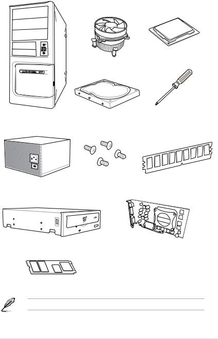
Installation tools and components
Intel® LGA1151 CPU
Intel® LGA1151 compatible CPU Fan
SATA hard disk drive |
Phillips (cross) screwdriver |
PC chassis |
|
1 bag of screws |
DIMM |
|
Power supply unit
SATA optical disc drive (optional)
Graphics card (optional)
M.2 SSD module (optional)
The tools and components above are not included in the motherboard package.
xv

xvi

Product Introduction |
1 |
1.1Motherboard overview
1.1.1Before you proceed
Take note of the following precautions before you install motherboard components or change any motherboard settings.
•Unplug the power cord from the wall socket before touching any component.
•Before handling components, use a grounded wrist strap or touch a safely grounded object or a metal object, such as the power supply case, to avoid damaging them due to static electricity.
•Hold components by the edges to avoid touching the ICs on them.
•Whenever you uninstall any component, place it on a grounded antistatic pad or in the bag that came with the component.
•Before you install or remove any component, ensure that the ATX power supply is switched off or the power cord is detached from the power supply. Failure to do so may cause severe damage to the motherboard, peripherals, or components.
Chapter 1
ASUS PRIME Z390-A |
1-1 |

1.1.2Motherboard layout
1 Chapter
Refer to 1.1.9 Internal connectors and 2.2.1 Rear I/O connection for more information about rear panel connectors and internal connectors.
1-2 |
Chapter 1: Product Introduction |

Layout contents
Connectors/Jumpers/Buttons and switches/Slots |
Page |
|
|
|
|
1. |
ATX power connectors (24-pin EATXPWR; 8-pin EATX12V) |
1-20 |
2. |
LGA1151 CPU Socket |
1-4 |
3. |
Fan and pump connectors (4-pin CPU_FAN; 4-pin CPU_OPT; 5-pin |
|
|
EXT_FAN; 4-pin W_PUMP+; 4-pin AIO_PUMP; 4-pin CHA_FAN1-2; 4-pin |
1-18 |
|
M.2_FAN) |
|
4. |
AURA RGB headers (4-pin RGB_HEADER1-2) |
1-23 |
5. |
DDR4 DIMM slots |
1-5 |
6. |
Power-on button (PWR_SW) |
1-9 |
7. |
MemOK! II switch (MemOK!_II) |
1-10 |
8. |
USB 3.1 Gen 1 Type-C™ front panel connector (U31G1_C5) |
1-15 |
9. |
Intel® Z390 Serial ATA 6 Gb/s connectors (7-pin SATA6G_12; SATA6G_34; |
1-14 |
|
SATA6G_56) |
|
|
|
|
10. |
Thermal sensor connector (2-pin T_SENSOR) |
1-17 |
11. |
Thunderbolt header (5-pin TB_HEADER) |
1-24 |
12. |
System panel connector (20-3 pin PANEL) |
1-21 |
13. |
Clear RTC RAM jumper (2-pin CLRTC) |
1-11 |
14. |
USB 2.0 connectors (10-1 pin USB_E12; USB_E34; USB_1112) |
1-17 |
15. |
USB 3.1 Gen 1 connector (20-1 pin U31G1_78) |
1-16 |
16. |
TPM connector (14-1 pin TPM) |
1-19 |
17. |
Node connector (12-1 pin NODE) |
1-19 |
18. |
Serial port connector (10-1 pin COM) |
1-24 |
19. |
Front panel audio connector (10-1 pin AAFP) |
1-15 |
20. |
M.2 sockets (M.2_1 (Socket 3); M.2_2 (Socket 3)) |
1-22 |
21. |
LED connector (8-pin LED1_CON) |
1-25 |
22. |
CPU Over Voltage jumper (3-pin CPU_OV) |
1-12 |
Chapter 1
ASUS PRIME Z390-A |
1-3 |
1 Chapter
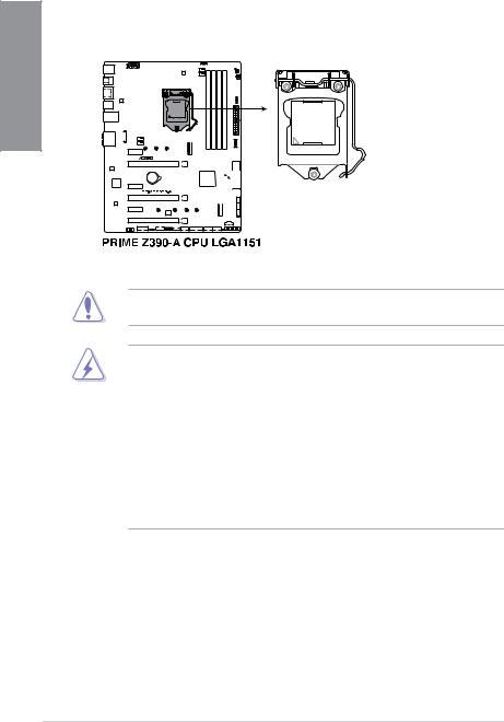
1.1.3Central Processing Unit (CPU)
This motherboard supports the Intel® Socket 1151 for Intel® Core™ 9000 series, 8th Generation Core™ i7/ i5/ i3, Pentium® and Celeron® processors, with memory and PCI Express controllers integrated to support dual-channel (4 DIMM) DDR4 memory and 16 PCI Express 3.0/2.0 lanes.
Ensure that you install the correct CPU designed for LGA1151 socket only. DO NOT install a CPU designed for LGA1150, LGA1155, and LGA1156 sockets in the LGA1151 socket.
•Ensure that all power cables are unplugged before installing the CPU.
•Upon purchase of the motherboard, ensure that the PnP cap is on the socket and the socket contacts are not bent. Contact your retailer immediately if the PnP cap is missing, or if you see any damage to the PnP cap/socket contacts/motherboard components. ASUS will shoulder the cost of repair only if the damage is shipment/ transit-related.
•Keep the cap after installing the motherboard. ASUS will process Return Merchandise Authorization (RMA) requests only if the motherboard comes with the cap on the LGA1151 socket.
•The product warranty does not cover damage to the socket contacts resulting from incorrect CPU installation/removal, or misplacement/loss/incorrect removal of the PnP cap.
1-4 |
Chapter 1: Product Introduction |
1.1.4System memory
The motherboard comes with four Double Data Rate 4 (DDR4) Dual Inline Memory Modules (DIMM) slots.
A DDR4 module is notched differently from a DDR, DDR2, or DDR3 module. DO NOT install a DDR, DDR2, or DDR3 memory module to the DDR4 slot.
Recommended memory configurations
Chapter 1
ASUS PRIME Z390-A |
1-5 |

1 Chapter
Memory configurations
You may install 2 GB, 4 GB, 8 GB and 16 GB unbuffered and non ECC DDR4 DIMMs into the DIMM sockets.
• The default memory operation frequency is dependent on its Serial Presence Detect (SPD), which is the standard way of accessing information from a memory module. Under the default state, some memory modules for overclocking may operate at a lower frequency than the vendor-marked value.
•For system stability, use a more efficient memory cooling system to support a full memory load (4 DIMMs) or overclocking condition.
•Always install the DIMMS with the same CAS Latency. For an optimum compatibility, we recommend that you install memory modules of the same version or data code (D/C) from the same vendor. Check with the vendor to get the correct memory modules.
•Visit the ASUS website for the latest QVL.
1-6 |
Chapter 1: Product Introduction |
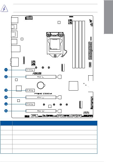
1.1.5Expansion slots
Unplug the power cord before adding or removing expansion cards. Failure to do so may cause you physical injury and damage motherboard components.
Slot No. Slot Description
1PCIe 3.0 x1_1 slot
2PCIe 3.0 x16_1 slot
3PCIe 3.0 x1_2 slot 4 PCIe 3.0 x16_2 slot 5 PCIe 3.0 x1_3 slot
6PCIe 3.0 x16_3 slot
Chapter 1
ASUS PRIME Z390-A |
1-7 |
1 Chapter
|
PCIe operating mode |
|
|
VGA Configuration |
|
|
|
PCIEX16_1 |
|
PCIEX16_2 |
|
|
|
||
|
|
|
|
Single VGA/PCIe card |
x16 (Recommend for single VGA) |
|
N/A |
|
|
|
|
Dual VGA/PCIe card |
x8 |
|
x8 |
|
|
|
|
•We recommend that you provide sufficient power when running CrossFireX™ or SLI® mode.
•Connect a chassis fan to the motherboard connector labeled CHA_FAN1-2 when using multiple graphics cards for better thermal environment.
•The PCIe x16_3 slot shares bandwidth with SATA6G_56. The PCIe x16_3 is set at x2 mode by default.
Hyper M.2 X16 series card |
PCI Express 3.0 operating mode |
|
|
|
|
|
|
|
configuration |
PCIEX16_1 |
PCIEX16_2 |
|
||
|
|
|
2 Intel® SSD on CPU support |
- |
x4+x4 |
3 Intel® SSD on CPU support |
x8+x4+x4 |
- |
• Hyper M.2 X16 series card sold separately
•Enable the Hyper M.2 X16 series card under BIOS settings.
1-8 |
Chapter 1: Product Introduction |
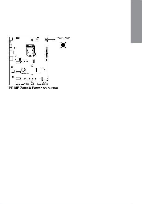
1.1.6Onboard buttons and switches
Onboard buttons and switches allow you to fine-tune performance when working on a bare or open-case system. This is ideal for overclockers and gamers who continually change settings to enhance system performance.
1. |
Power-on button (PWR_SW) |
1 |
|||||||||||||||||||||||||||||||||||||||
Chapter |
|||||||||||||||||||||||||||||||||||||||||
|
The motherboard comes with a power-on button that allows you to power up or wake |
||||||||||||||||||||||||||||||||||||||||
|
|
||||||||||||||||||||||||||||||||||||||||
|
up the system. The LED near the button also lights up when the system is plugged to |
|
|||||||||||||||||||||||||||||||||||||||
|
a power source indicating that you should shut down the system and unplug the power |
|
|||||||||||||||||||||||||||||||||||||||
|
cable before removing or installing any motherboard component. |
|
|||||||||||||||||||||||||||||||||||||||
|
|
|
|
|
|
|
|
|
|
|
|
|
|
|
|
|
|
|
|
|
|
|
|
|
|
|
|
|
|
|
|
|
|
|
|
|
|
|
|
|
|
|
|
|
|
|
|
|
|
|
|
|
|
|
|
|
|
|
|
|
|
|
|
|
|
|
|
|
|
|
|
|
|
|
|
|
|
|
|
|
|
|
|
|
|
|
|
|
|
|
|
|
|
|
|
|
|
|
|
|
|
|
|
|
|
|
|
|
|
|
|
|
|
|
|
|
|
|
|
|
|
|
|
|
|
|
|
|
|
|
|
|
|
|
|
|
|
|
|
|
|
|
|
|
|
|
|
|
|
|
|
|
|
|
|
|
|
|
|
|
|
|
|
|
|
|
|
|
|
|
|
|
|
|
|
|
|
|
|
|
|
|
|
|
|
|
|
|
|
|
|
|
|
|
|
|
|
|
|
|
|
|
|
|
|
|
|
|
|
|
|
|
|
|
|
|
|
|
|
|
|
|
|
|
|
|
|
|
|
|
|
|
|
|
|
|
|
|
|
|
|
|
|
|
|
|
|
|
|
|
|
|
|
|
|
|
|
|
|
|
|
|
|
|
|
|
|
|
|
|
|
|
|
|
|
|
|
|
|
|
|
|
|
|
|
|
|
|
|
|
|
|
|
|
|
|
|
|
|
|
|
|
|
|
|
|
|
|
|
|
|
|
|
|
|
|
|
|
|
|
|
|
|
|
|
|
|
|
|
|
|
|
|
|
|
|
|
|
|
|
|
|
|
|
|
|
|
|
|
|
|
|
|
|
|
|
|
|
|
|
|
|
|
|
|
|
|
|
|
|
|
|
|
|
|
|
|
|
|
|
|
|
|
|
|
|
|
|
|
|
|
|
|
|
|
|
|
|
|
|
|
|
|
|
|
|
|
|
|
|
|
|
|
|
|
|
|
|
|
|
|
|
|
|
|
|
|
|
|
|
|
|
|
|
|
|
|
|
|
|
|
|
|
|
|
|
|
|
|
|
|
|
|
|
|
|
|
|
|
|
|
|
|
|
|
|
|
|
|
|
|
|
|
|
|
|
|
|
|
|
|
|
|
|
|
|
|
|
|
|
|
|
|
|
|
|
|
|
|
|
|
|
|
|
|
|
|
|
|
|
|
|
|
|
|
|
|
|
|
|
|
|
|
|
|
|
|
|
|
|
|
|
|
|
|
|
|
|
|
|
|
|
|
|
|
|
|
|
|
|
|
|
|
|
|
|
|
|
|
|
|
|
|
|
|
|
|
|
|
|
|
|
|
|
|
|
|
|
|
|
|
|
|
|
|
|
|
|
|
|
|
|
|
|
|
|
|
|
|
|
|
|
|
|
|
|
|
|
|
|
|
|
|
|
|
|
|
|
|
|
|
|
|
|
|
|
|
|
|
|
|
|
|
|
|
|
|
|
|
|
|
|
|
|
|
|
|
|
|
|
|
|
|
|
|
|
|
|
|
|
|
|
|
|
|
|
|
|
|
|
|
|
|
|
|
|
|
|
|
|
|
|
|
|
|
|
|
|
|
|
|
|
|
|
|
|
|
|
|
|
|
|
|
|
|
|
|
|
|
|
|
|
|
|
|
|
|
|
|
|
|
|
|
|
|
|
|
|
|
|
|
|
|
|
|
|
|
|
|
|
|
|
|
|
|
|
|
|
|
|
|
|
|
|
|
|
|
|
|
|
|
|
|
|
|
|
|
|
|
|
|
|
|
|
|
|
|
|
|
|
|
|
|
|
|
|
|
|
|
|
|
|
|
|
|
|
|
|
|
|
|
|
|
|
|
|
|
|
|
|
|
|
|
|
|
|
|
|
|
|
|
|
|
|
|
|
|
|
|
|
|
|
|
|
|
|
|
|
|
|
|
|
|
|
|
|
|
|
|
|
|
|
|
|
|
|
|
|
|
|
|
|
|
|
|
|
|
|
|
|
|
|
|
|
|
|
|
|
|
|
|
|
|
|
|
|
|
|
|
|
|
|
|
|
|
|
|
|
|
|
|
|
|
|
|
|
|
|
|
|
|
|
|
|
|
|
|
|
|
|
|
|
|
ASUS PRIME Z390-A |
1-9 |
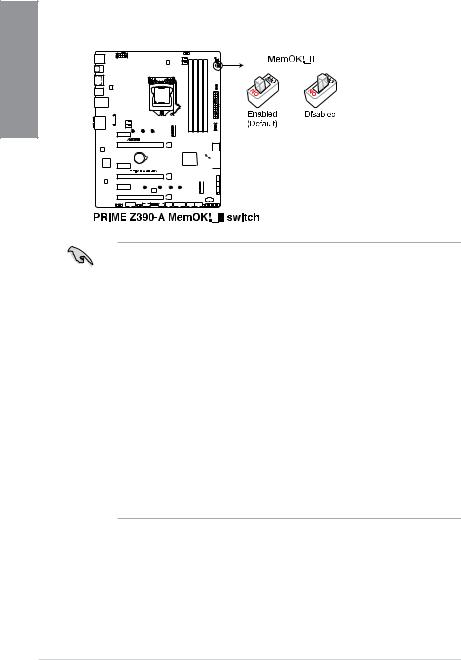
2. |
MemOK! II switch (MemOK!_II) |
|
Installing DIMMs that are not compatible with the motherboard may cause system |
|
boot failure. The switch is enabled by default, allowing memory re-training when the |
1 Chapter |
motherboard is unresponsive due to memory problems. The Mem_LED will light up |
while re-training, and turn off when the re-training is complete. |
|
|
•Refer to section 1.1.8 Onboard LEDs for the exact location of the Mem_LED.
•The DRAM LED also lights up when the DIMM is not properly installed. Turn off the system and reinstall the DIMM before using the MemOK! II function.
•The MemOK! II switch does not function under Windows® OS environment.
•During the tuning process, the system loads and tests pretest profiles. It takes about 30 seconds for the system to test one set of profiles. If the test fails, the system reboots and tests the next set of profiles. The system will reboot multiple times when training, once the system has completed the training process the Mem_LED will turn off, please refrain from doing anything before the Mem_LED turns off.
•Due to memory tuning requirement, the system automatically reboots when each profile is tested.
•If you turn off the computer and replace DIMMs during the tuning process, the system continues memory tuning after turning on the computer. To stop memory tuning, turn off the computer and unplug the power cord for about 5–10 seconds, then set the MemOK! II switch to disabled.
•Ensure to replace the DIMMs with ones recommended in the Memory QVL (Qualified Vendors Lists) at www.asus.com.
•We recommend that you download and update to the latest BIOS version from www.asus.com after using the MemOK! II function.
1-10 |
Chapter 1: Product Introduction |
1.1.7Jumper
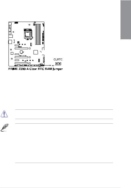
1. Clear RTC RAM jumper (2-pin CLRTC) |
|
|
This jumper allows you to clear the Real Time Clock (RTC) RAM in CMOS. You can |
|
|
clear the CMOS memory of date, time, and system setup parameters by erasing the |
1 |
|
CMOS RTC RAM data. The onboard button cell battery powers the RAM data in |
||
Chapter |
||
CMOS, which include system setup information such as system passwords. |
||
|
To erase the RTC RAM:
1.Turn OFF the computer and unplug the power cord.
2.Short-circuit pin 1-2 with a metal object or jumper cap for about 5-10 seconds.
3.Plug the power cord and turn ON the computer.
4.Hold down the <Delete> key during the boot process and enter BIOS setup to re-enter data.
Except when clearing the RTC RAM, never place a metal object or jumper cap on the
CLRTC jumper. Placing a metal object or jumper cap will cause system boot failure!
•If the steps above do not help, remove the onboard battery and place a metal object or jumper cap again to clear the CMOS RTC RAM data. After the CMOS clearance, reinstall the battery.
•You do not need to clear the RTC when the system hangs due to overclocking. For system failure due to overclocking, use the C.P.R. (CPU Parameter Recall) feature. Shut down and reboot the system so the BIOS can automatically reset parameter settings to default values.
•Due to the chipset behavior, AC power off is required to enable C.P.R. function. You must turn off and turn on the power supply or unplug and plug the power cord before rebooting the system.
ASUS PRIME Z390-A |
1-11 |
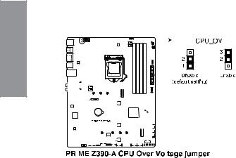
2. |
CPU Over Voltage jumper (3-pin CPU_OV) |
|
The CPU Over Voltage jumper allows you to set a higher CPU voltage for a flexible |
|
overclocking system, depending on the type of the installed CPU. To gain more CPU |
1 Chapter |
voltage setting, insert the jumper to pins 2-3. To go back to its default CPU voltage |
setting, insert the jumper to pins 1-2. |
|
|
|
|
|
|
|
|
|
|
|
|
|
|
|
|
|
|
|
|
|
|
|
|
|
|
|
|
|
|
|
|
|
|
|
|
|
|
|
|
|
|
|
|
|
|
|
|
|
|
|
|
|
|
|
|
|
|
|
|
|
|
|
|
|
|
|
|
|
|
|
|
|
|
|
|
|
|
|
|
|
|
|
|
|
|
|
|
|
|
|
|
|
|
|
|
|
|
|
|
|
|
|
|
|
|
|
|
|
|
|
|
|
|
|
|
|
|
|
|
|
|
|
|
|
|
|
|
|
|
|
|
|
|
|
|
|
|
|
|
|
|
|
|
|
|
|
|
|
|
|
|
|
|
|
|
|
|
|
|
|
|
|
|
|
|
|
|
|
|
|
|
|
|
|
|
|
|
|
|
|
|
|
|
|
|
|
|
|
|
|
|
|
|
|
|
|
|
|
|
|
|
|
|
|
|
|
|
|
|
|
|
|
|
|
|
|
|
|
|
|
|
|
|
|
|
|
|
|
|
|
|
|
|
|
|
|
|
|
|
|
|
|
|
|
|
|
|
|
|
|
|
|
|
|
|
|
|
|
|
|
|
|
|
|
|
|
|
|
|
|
|
|
|
|
|
|
|
|
|
|
|
|
|
|
|
|
|
|
|
|
|
|
|
|
|
|
|
|
|
|
|
|
|
|
|
|
|
|
|
|
|
|
|
|
|
|
|
|
|
|
|
|
|
|
|
|
|
|
|
|
|
|
|
|
|
|
|
|
|
|
|
|
|
|
|
|
|
|
|
|
|
|
|
|
|
|
|
|
|
|
|
|
|
|
|
|
|
|
|
|
|
|
|
|
|
|
|
|
|
|
|
|
|
|
|
|
|
|
|
|
|
|
|
|
|
|
|
|
|
|
|
|
|
|
|
|
|
|
|
|
|
|
|
|
|
|
|
|
|
|
|
|
|
|
|
|
|
|
|
|
|
|
|
|
|
|
|
|
|
|
|
|
|
|
|
1-12 |
|
|
|
|
|
|
|
|
|
|
|
|
|
|
|
|
|
|
|
|
|
|
|
|
|
|
|
|
|
|
|
|
|
|
|
Chapter 1: Product Introduction |
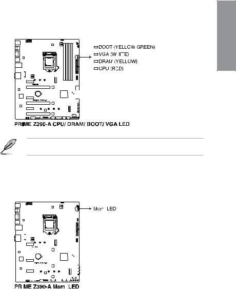
1.1.8Onboard LEDs
1. |
Q LEDs (BOOT_LED, VGA_LED, DRAM_LED, CPU_LED) |
|
|
Q LEDs check key components (CPU, DRAM, VGA card, and booting devices) in |
|
|
sequence during motherboard booting process. If an error is found, the corresponding |
1 |
|
LED remains lit until the problem is solved. This user-friendly design provides an |
|
|
Chapter |
|
|
intuitive way to locate the root problem within seconds. |
|
|
|
The Q LEDs provide the most probable cause of an error code as a starting point for troubleshooting. The actual cause may vary from case to case.
2.Memory LED (Mem_LED)
The Mem_LED will light up and remain lit while the MemOK! II function is in use. When the re-training is complete, the Mem_LED will turn off.
|
|
|
|
|
|
|
|
|
|
|
|
|
|
|
|
|
|
|
|
|
|
|
|
|
|
|
|
|
|
|
|
|
|
|
|
|
|
|
|
|
|
|
|
|
|
|
|
|
|
|
|
|
|
|
|
|
|
|
|
|
|
|
|
|
|
|
|
|
|
|
|
|
|
|
|
|
|
|
|
|
|
|
|
|
|
|
|
|
|
|
|
|
|
|
|
|
|
|
|
|
|
|
|
|
|
|
|
|
|
|
|
|
|
|
|
|
|
|
|
|
|
|
|
|
|
|
|
|
|
|
|
|
|
|
|
|
|
|
|
|
|
|
|
|
|
|
|
|
|
|
|
|
|
|
|
|
|
|
|
|
|
|
|
|
|
|
|
|
|
|
|
|
|
|
|
|
|
|
|
|
|
|
|
|
|
|
|
|
|
|
|
|
|
|
|
|
|
|
|
|
|
|
|
|
|
|
|
|
|
|
|
|
|
|
|
|
|
|
|
|
|
|
|
|
|
|
|
|
|
|
|
|
|
|
|
|
|
|
|
|
|
|
|
|
|
|
|
|
|
|
|
|
|
|
|
|
|
|
|
|
|
|
|
|
|
|
|
|
|
|
|
|
|
|
|
|
|
|
|
|
|
|
|
|
|
|
|
|
|
|
|
|
|
|
|
|
|
|
|
|
|
|
|
|
|
|
|
|
|
|
|
|
|
|
|
|
|
|
|
|
|
|
|
|
|
|
|
|
|
|
|
|
|
|
|
|
|
|
|
|
|
|
|
|
|
|
|
|
|
|
|
|
|
|
|
|
|
|
|
|
|
|
|
|
|
|
|
|
|
|
|
|
|
|
|
|
|
|
|
|
|
|
|
|
|
|
|
|
|
|
|
|
|
|
|
|
|
|
|
|
|
|
|
|
|
|
|
|
|
|
|
|
|
|
|
|
|
|
|
|
|
|
|
|
|
|
|
|
|
|
|
|
|
|
|
|
|
|
|
|
|
|
|
|
|
|
|
|
|
|
|
|
|
|
|
|
|
|
|
|
|
|
|
|
|
|
|
|
|
|
|
|
|
|
|
|
|
|
|
|
|
|
|
|
|
|
|
|
|
|
|
|
|
|
|
|
|
|
|
|
|
|
|
|
|
|
|
|
|
|
|
|
|
|
|
|
|
|
|
|
|
|
|
|
|
|
|
|
|
|
|
|
|
|
|
|
|
|
|
|
|
|
|
|
|
|
|
|
|
|
|
|
|
|
|
|
|
|
|
|
|
|
|
|
|
|
|
|
|
|
|
|
|
|
|
|
|
|
|
|
|
|
|
|
|
|
|
|
|
|
|
|
|
|
|
|
|
|
|
|
|
|
|
|
|
|
|
|
|
|
|
|
|
|
|
|
|
|
|
|
|
|
|
|
|
|
|
|
|
|
|
|
|
|
|
|
|
|
|
|
|
|
|
|
|
|
|
|
|
|
|
|
|
|
|
|
|
|
|
|
|
|
|
|
|
|
|
|
|
|
|
|
|
|
|
|
|
|
|
|
|
|
|
|
|
|
|
|
|
|
|
|
|
|
|
|
|
|
|
|
|
|
|
|
|
|
|
|
|
|
|
|
|
|
|
|
|
|
|
|
|
|
|
|
|
|
|
|
|
|
|
|
|
|
|
|
|
|
|
|
|
|
|
|
|
|
|
|
|
|
|
|
|
|
|
|
|
|
|
|
|
|
|
|
|
|
|
|
|
|
|
|
|
|
|
|
|
|
|
|
|
|
|
|
|
|
|
|
|
|
|
|
|
|
|
|
|
|
|
|
|
|
|
|
|
|
|
|
|
|
|
|
|
|
|
|
|
|
|
|
|
|
|
|
|
|
|
|
|
|
|
|
|
|
|
ASUS PRIME Z390-A |
1-13 |
||||||||||||||||||||||||||||||||||||
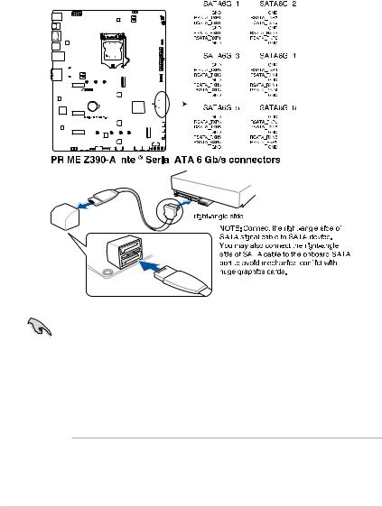
1.1.9Internal connectors
|
1. |
Intel® Z390 Serial ATA 6 Gb/s connectors (7-pin SATA6G_12; SATA6G_34; |
|||||||||||||||||||||||||||||||||||||||||||||||
|
|
SATA6G_56) |
|||||||||||||||||||||||||||||||||||||||||||||||
1Chapter |
|
These connectors connect to Serial ATA 6 Gb/s hard disk drives via Serial ATA 6 Gb/s |
|||||||||||||||||||||||||||||||||||||||||||||||
|
signal cables. |
||||||||||||||||||||||||||||||||||||||||||||||||
|
|
||||||||||||||||||||||||||||||||||||||||||||||||
|
|
If you installed Serial ATA hard disk drives, you can create a RAID 0, 1, 5, and 10 |
|||||||||||||||||||||||||||||||||||||||||||||||
|
|
configuration with the Intel® Rapid Storage Technology through the onboard Intel® |
|||||||||||||||||||||||||||||||||||||||||||||||
|
|
Z390 chipset. |
|||||||||||||||||||||||||||||||||||||||||||||||
|
|
|
|
|
|
|
|
|
|
|
|
|
|
|
|
|
|
|
|
|
|
|
|
|
|
|
|
|
|
|
|
|
|
|
|
|
|
|
|
|
|
|
|
|
|
|
|
|
|
|
|
|
|
|
|
|
|
|
|
|
|
|
|
|
|
|
|
|
|
|
|
|
|
|
|
|
|
|
|
|
|
|
|
|
|
|
|
|
|
|
|
|
|
|
|
|
|
|
|
|
|
|
|
|
|
|
|
|
|
|
|
|
|
|
|
|
|
|
|
|
|
|
|
|
|
|
|
|
|
|
|
|
|
|
|
|
|
|
|
|
|
|
|
|
|
|
|
|
|
|
|
|
|
|
|
|
|
|
|
|
|
|
|
|
|
|
|
|
|
|
|
|
|
|
|
|
|
|
|
|
|
|
|
|
|
|
|
|
|
|
|
|
|
|
|
|
|
|
|
|
|
|
|
|
|
|
|
|
|
|
|
|
|
|
|
|
|
|
|
|
|
|
|
|
|
|
|
|
|
|
|
|
|
|
|
|
|
|
|
|
|
|
|
|
|
|
|
|
|
|
|
|
|
|
|
|
|
|
|
|
|
|
|
|
|
|
|
|
|
|
|
|
|
|
|
|
|
|
|
|
|
|
|
|
|
|
|
|
|
|
|
|
|
|
|
|
|
|
|
|
|
|
|
|
|
|
|
|
|
|
|
|
|
|
|
|
|
|
|
|
|
|
|
|
|
|
|
|
|
|
|
|
|
|
|
|
|
|
|
|
|
|
|
|
|
|
|
|
|
|
|
|
|
|
|
|
|
|
|
|
|
|
|
|
|
|
|
|
|
|
|
|
|
|
|
|
|
|
|
|
|
|
|
|
|
|
|
|
|
|
|
|
|
|
|
|
|
|
|
|
|
|
|
|
|
|
|
|
|
|
|
|
|
|
|
|
|
|
|
|
|
|
|
|
|
|
|
|
|
|
|
|
|
|
|
|
|
|
|
|
|
|
|
|
|
|
|
|
|
|
|
|
|
|
|
|
|
|
|
|
|
|
|
|
|
|
|
|
|
|
|
|
|
|
|
|
|
|
|
|
|
|
|
|
|
|
|
|
|
|
|
|
|
|
|
|
|
|
|
|
|
|
|
|
|
|
|
|
|
|
|
|
|
|
|
|
|
|
|
|
|
|
|
|
|
|
|
|
|
|
|
|
|
|
|
|
|
|
|
|
|
|
|
|
|
|
|
|
|
|
|
|
|
|
|
|
|
|
|
|
|
|
|
|
|
|
|
|
|
|
|
|
|
|
|
|
|
|
|
|
|
|
|
|
|
|
|
|
|
|
|
|
|
|
|
|
|
|
|
|
|
|
|
|
|
|
|
|
|
|
|
|
|
|
|
|
|
|
|
|
|
|
|
|
|
|
|
|
|
|
|
|
|
|
|
|
|
|
|
|
|
|
|
|
|
|
|
|
|
|
|
|
|
|
|
|
|
|
|
|
|
|
|
|
|
|
|
|
|
|
|
|
|
|
|
|
|
|
|
|
|
|
|
|
|
|
|
|
|
|
|
|
|
|
|
|
|
|
|
|
|
|
|
|
|
|
|
|
|
|
|
|
|
|
|
|
|
|
|
|
|
|
|
|
|
|
|
|
|
|
|
|
|
|
|
|
|
|
|
|
|
|
|
|
|
|
|
|
|
|
|
|
|
|
|
|
|
|
|
|
|
|
|
|
|
|
|
|
|
|
|
|
|
|
|
|
|
|
|
|
|
|
|
|
|
|
|
|
|
|
|
|
|
|
|
|
|
|
|
|
|
|
|
|
|
|
|
|
|
|
|
|
|
|
|
|
|
|
|
|
|
|
|
|
|
|
|
|
|
|
|
|
|
|
|
|
|
|
|
|
|
|
|
|
|
|
|
|
|
|
|
|
|
|
|
|
|
|
|
|
|
|
|
|
|
|
|
|
|
|
|
|
|
|
|
|
|
|
|
|
|
|
|
|
|
|
|
|
|
|
|
|
|
|
|
|
|
|
|
|
|
|
|
|
|
|
|
|
|
|
|
|
|
|
|
|
|
|
|
|
|
|
|
|
|
|
|
|
|
|
|
|
|
|
|
|
|
|
|
|
|
|
|
|
|
|
|
|
|
|
|
|
|
|
|
|
|
|
|
|
|
|
|
|
|
|
|
|
|
|
|
|
|
|
|
|
|
|
|
|
|
|
|
|
|
|
|
|
|
|
|
|
|
|
|
|
|
|
|
|
|
|
|
|
|
|
|
|
|
|
|
|
|
|
|
|
|
|
|
|
|
|
|
|
|
|
|
|
|
|
|
|
|
|
|
|
|
|
|
|
|
|
|
|
|
|
|
|
|
|
|
|
|
|
|
|
|
|
|
|
|
|
|
|
|
|
|
|
|
|
|
|
|
|
|
|
|
|
|
|
|
|
|
|
|
|
|
|
|
|
|
|
|
|
|
|
|
|
|
|
|
|
|
|
|
|
|
|
|
|
|
|
|
|
|
|
|
|
|
|
|
|
|
|
|
|
|
|
|
|
|
|
|
|
|
|
|
|
|
|
|
|
|
|
|
|
|
|
|
•The PCIe x16_3 slot shares bandwidth with SATA6G_56. The PCIe x16_3 is set at x2 mode by default.
•The M.2_1 socket shares bandwidth with SATA6G_2 port when using M.2 SATA devices. Adjust BIOS settings to use a SATA device.
•These connectors are set to [AHCI] by default. If you intend to create a Serial ATA RAID set using these connectors, set the SATA Mode Selection item in the BIOS to [Intel RST Premium With Intel Optane System Acceleration (RAID)].
•For more information on configuring your RAID sets, please refer to the RAID Configuration Guide which you can find at https://www.asus.com/support.
1-14 |
Chapter 1: Product Introduction |
Loading...