


Z77-A
Motherboard

E8090 First Edition
January 2013
Copyright © 2013 ASUSTeK Computer Inc. All Rights Reserved.
No part of this manual, including the products and software described in it, may be reproduced, transmitted, transcribed, stored in a retrieval system, or translated into any language in any form or by any means, except documentation kept by the purchaser for backup purposes, without the express written permission of ASUSTeK Computer Inc. (“ASUS”).
Product warranty or service will not be extended if: (1) the product is repaired, modified or altered, unless such repair, modification of alteration is authorized in writing byASUS; or (2) the serial number of the product is defaced or missing.
ASUS PROVIDES THIS MANUAL “AS IS” WITHOUT WARRANTY OF ANY KIND, EITHER EXPRESS OR IMPLIED, INCLUDING BUT NOT LIMITED TO THE IMPLIED WARRANTIES OR CONDITIONS OF MERCHANTABILITY OR FITNESS FOR A PARTICULAR PURPOSE. IN NO EVENT SHALL ASUS, ITS DIRECTORS, OFFICERS, EMPLOYEES OR AGENTS BE LIABLE FOR ANY INDIRECT, SPECIAL, INCIDENTAL, OR CONSEQUENTIAL DAMAGES (INCLUDING DAMAGES FOR LOSS OF PROFITS, LOSS OF BUSINESS, LOSS OF USE OR DATA, INTERRUPTION OF BUSINESS AND THE LIKE), EVEN IF ASUS HAS BEEN ADVISED OF THE POSSIBILITY OF SUCH DAMAGES ARISING FROM ANY DEFECT OR ERROR IN THIS MANUAL OR PRODUCT.
SPECIFICATIONS AND INFORMATION CONTAINED IN THIS MANUAL ARE FURNISHED FOR INFORMATIONAL USE ONLY, AND ARE SUBJECT TO CHANGE AT ANY TIME WITHOUT NOTICE, AND SHOULD NOT BE CONSTRUED AS A COMMITMENT BY ASUS. ASUS ASSUMES NO RESPONSIBILITY OR LIABILITY FOR ANY ERRORS OR INACCURACIES THAT MAY APPEAR IN THIS MANUAL, INCLUDING THE PRODUCTS AND SOFTWARE DESCRIBED IN IT.
Products and corporate names appearing in this manual may or may not be registered trademarks or copyrights of their respective companies, and are used only for identification or explanation and to the owners’ benefit, without intent to infringe.
Offer to Provide Source Code of Certain Software
This product may contain copyrighted software that is licensed under the General Public License (“GPL”) and under the Lesser General Public License Version (“LGPL”). The GPL and LGPL licensed code in this product is distributed without any warranty. Copies of these licenses are included in this product.
You may obtain the complete corresponding source code (as defined in the GPL) for the GPL Software, and/or the complete corresponding source code of the LGPL Software (with the complete machinereadable “work that uses the Library”) for a period of three years after our last shipment of the product including the GPL Software and/or LGPL Software, which will be no earlier than December 1, 2011, either
(1)for free by downloading it from http://support.asus.com/download;
or
(2)for the cost of reproduction and shipment, which is dependent on the preferred carrier and the location where you want to have it shipped to, by sending a request to:
ASUSTeK Computer Inc.
Legal Compliance Dept.
15 Li Te Rd.,
Beitou, Taipei 112
Taiwan
In your request please provide the name, model number and version, as stated in the About Box of the product for which you wish to obtain the corresponding source code and your contact details so that we can coordinate the terms and cost of shipment with you.
The source code will be distributed WITHOUT ANY WARRANTY and licensed under the same license as the corresponding binary/object code.
This offer is valid to anyone in receipt of this information.
ASUSTeK is eager to duly provide complete source code as required under various Free Open Source Software licenses. If however you encounter any problems in obtaining the full corresponding source code we would be much obliged if you give us a notification to the email address gpl@asus.com, stating the product and describing the problem (please do NOT send large attachments such as source code archives etc to this email address).
ii

Contents
Safety information....................................................................................... |
vi |
About this guide......................................................................................... |
vii |
Z77-A specifications summary................................................................... |
ix |
Package contents....................................................................................... |
xii |
Product introduction
1.1 |
Product highlights........................................................................ |
1-1 |
|
1.2 |
Before you proceed...................................................................... |
1-4 |
|
1.3 |
Motherboard overview................................................................. |
1-5 |
|
|
1.3.1 |
Placement direction ......................................................... |
1-5 |
|
1.3.2 |
Screw holes ..................................................................... |
1-5 |
|
1.3.3 |
Motherboard layout .......................................................... |
1-6 |
|
1.3.4 |
Layout contents . .............................................................. |
1-7 |
1.4 |
Intel® CPU LGA1155 socket......................................................... |
1-7 |
|
|
1.4.1 |
CPU installation ............................................................... |
1-8 |
|
1.4.2 |
CPU heatsink and fan assembly installation ................... |
1-9 |
1.5 |
System memory.......................................................................... |
1-11 |
|
|
1.5.1 |
Overview ......................................................................... |
1-11 |
|
1.5.2 |
Memory configurations . ................................................. |
1-12 |
|
1.5.3 |
Installing a DIMM ........................................................... |
1-19 |
1.6 |
Expansion slots.......................................................................... |
1-20 |
|
1.7 |
Jumpers |
....................................................................................... |
1-22 |
1.8 |
Connectors.................................................................................. |
1-24 |
|
|
1.8.1 ............................................................ |
Rear panel ports |
1-24 |
|
1.8.2 ........................................................ |
Internal connectors |
1-26 |
1.9 |
Software ........................................................................support |
1-34 |
|
|
1.9.1 ....................................... |
Installing an operating system |
1-34 |
|
1.9.2 ............................................... |
Support DVD information |
1-34 |
iii

Contents
BIOS information
2.1 |
Managing and updating your BIOS............................................. |
2-1 |
|
|
2.1.1 |
ASUS Update utility......................................................... |
2-1 |
|
2.1.2 |
ASUS EZ Flash 2............................................................ |
2-2 |
|
2.1.3 |
ASUS CrashFree BIOS 3 utility....................................... |
2-3 |
|
2.1.4 |
ASUS BIOS Updater....................................................... |
2-4 |
2.2 |
BIOS setup program..................................................................... |
2-7 |
|
2.3 |
Main menu................................................................................... |
2-11 |
|
|
2.3.1 |
System Language [English]............................................ |
2-11 |
|
2.3.2 |
System Date [Day xx/xx/xxxx]........................................ |
2-11 |
|
2.3.3 |
System Time [xx:xx:xx]................................................... |
2-11 |
|
2.3.4 |
Security........................................................................... |
2-11 |
2.4 |
Ai Tweaker menu........................................................................ |
2-13 |
|
|
2.4.1 |
Ai Overclock Tuner [Auto].............................................. |
2-14 |
|
2.4.2 |
ASUS MultiCore Enhancement [Enabled]..................... |
2-14 |
|
2.4.3 |
Turbo Ratio [Auto].......................................................... |
2-14 |
|
2.4.4 |
Internal PLL Overvoltage [Auto]..................................... |
2-14 |
|
2.4.5 |
Memory Frequency [Auto]............................................. |
2-15 |
|
2.4.6 |
iGPU Max. Frequency [Auto]......................................... |
2-15 |
|
2.4.7 |
EPU Power Saving Mode [Disabled]............................. |
2-15 |
|
2.4.8 |
OC Tuner....................................................................... |
2-15 |
|
2.4.9 |
DRAM Timing Control.................................................... |
2-15 |
|
2.4.10 |
CPU Power Management.............................................. |
2-15 |
|
2.4.11 |
DIGI+ VRM.................................................................... |
2-16 |
2.5 |
Advanced menu.......................................................................... |
2-20 |
|
|
2.5.1 |
CPU Configuration......................................................... |
2-20 |
|
2.5.2 |
PCH Configuration......................................................... |
2-23 |
|
2.5.3 |
SATAConfiguration........................................................ |
2-24 |
|
2.5.4 |
SystemAgent Configuration.......................................... |
2-25 |
|
2.5.5 |
USB Configuration......................................................... |
2-26 |
|
2.5.6 |
Onboard Devices Configuration.................................... |
2-27 |
|
2.5.7 |
APM............................................................................... |
2-28 |
|
2.5.8 |
Network Stack............................................................... |
2-29 |
iv

Contents
2.6 |
Monitor menu.............................................................................. |
2-30 |
|
|
2.6.1 |
CPU Temperature / MB Temperature [xxxºC/xxxºF]...... |
2-31 |
|
2.6.2 |
CPU / Chassis Fan 1/2 / PWR Fan Speed ................... |
2-31 |
|
2.6.3 |
CPU Voltage, 3.3V Voltage, 5V Voltage, 12V Voltage... |
2-31 |
|
2.6.4 |
CPU Q-Fan Control [Enabled]....................................... |
2-31 |
|
2.6.5 |
CPU Fan Speed Low Limit [200 RPM].......................... |
2-31 |
|
2.6.6 |
Chassis1/2 Q-Fan Control [Enabled]............................. |
2-32 |
|
2.6.7 |
Chassis Fan Speed Low Limit [600 RPM]..................... |
2-32 |
|
2.6.8 |
Anti Surge Support [Enabled]........................................ |
2-33 |
2.7 |
Boot menu................................................................................... |
2-34 |
|
|
2.7.1 |
Fast Boot [Enabled]....................................................... |
2-35 |
|
2.7.2 |
Full Screen Logo [Enabled]........................................... |
2-35 |
|
2.7.3 |
Post Delay Time [3 sec]................................................. |
2-36 |
|
2.7.4 |
Bootup NumLock State [On].......................................... |
2-36 |
|
2.7.5 |
Wait for ‘F1’ If Error [Enabled]....................................... |
2-36 |
|
2.7.6 |
Option ROM Messages [Force BIOS]........................... |
2-36 |
|
2.7.7 |
Interrupt 19 Capture [Postponed].................................. |
2-36 |
|
2.7.8 |
Setup Mode [EZ Mode].................................................. |
2-36 |
|
2.7.9 |
CSM (Compatibility Support Module)............................ |
2-36 |
|
2.7.10 |
Secure Boot................................................................... |
2-38 |
|
2.7.11 |
Boot Option Priorities..................................................... |
2-39 |
|
2.7.12 |
Boot Override................................................................ |
2-39 |
2.8 |
Tools menu.................................................................................. |
2-40 |
|
|
2.8.1 |
ASUS EZ Flash 2 Utility................................................. |
2-40 |
|
2.8.2 |
ASUS O.C. Profile......................................................... |
2-40 |
|
2.8.3 |
ASUS SPD Information................................................. |
2-40 |
2.9 |
Exit menu..................................................................................... |
2-41 |
|
Appendices
Notices....................................................................................................... |
A-1 |
ASUS contact information........................................................................ |
A-3 |

Safety information
Electrical safety
•To prevent electric shock hazard, disconnect the power cable from the electric outlet before relocating the system.
•When adding or removing devices to or from the system, ensure that the power cables for the devices are unplugged before the signal cables are connected. If possible, disconnect all power cables from the existing system before you add a device.
•Before connecting or removing signal cables from the motherboard, ensure that all power cables are unplugged.
•Seek professional assistance before using an adapter or extension cord. These devices could interrupt the grounding circuit.
•Ensure that your power supply is set to the correct voltage in your area. If you are not sure about the voltage of the electrical outlet you are using, contact your local power company.
•If the power supply is broken, do not try to fix it by yourself. Contact a qualified service technician or your retailer.
Operation safety
•Before installing the motherboard and adding devices on it, carefully read all the manuals that came with the package.
•Before using the product, ensure that all cables are correctly connected and the power cables are not damaged. If you detect any damage, contact your dealer immediately.
•To avoid short circuits, keep paper clips, screws, and staples away from connectors, slots, sockets and circuitry.
•Avoid dust, humidity, and temperature extremes. Do not place the product in any area where it may become wet.
•Place the product on a stable surface.
•If you encounter technical problems with the product, contact a qualified service technician or your retailer.
vi

About this guide
This user guide contains the information you need when installing and configuring the motherboard.
How this guide is organized
This guide contains the following parts:
•Chapter 1: Product introduction
This chapter describes the features of the motherboard and the new technology it supports.
•Chapter 2: BIOS information
This chapter tells how to change system settings through the BIOS Setup menus. Detailed descriptions of the BIOS parameters are also provided.
Where to find more information
Refer to the following sources for additional information and for product and software updates.
1.ASUS websites
The ASUS website provides updated information on ASUS hardware and software products. Refer to the ASUS contact information.
2.Optional documentation
Your product package may include optional documentation, such as warranty flyers, that may have been added by your dealer. These documents are not part of the standard package.
vii

Conventions used in this guide
To ensure that you perform certain tasks properly, take note of the following symbols used throughout this manual.
DANGER/WARNING: Information to prevent injury to yourself when trying to complete a task.
CAUTION: Information to prevent damage to the components when trying to complete a task
IMPORTANT: Instructions that you MUST follow to complete a task .
NOTE: Tips and additional information to help you complete a task.
Typography
Bold text |
Indicates a menu or an item to select. |
Italics |
Used to emphasize a word or a phrase. |
<Key> |
Keys enclosed in the less-than and greater-than sign |
|
means that you must press the enclosed key. |
|
Example: <Enter> means that you must press the Enter or |
|
Return key. |
<Key1> + <Key2> + <Key3> |
If you must press two or more keys simultaneously, the key |
|
names are linked with a plus sign (+). |
viii

Z77-A specifications summary
CPU
Chipset
Memory
Expansion slots
Graphics
Multi-GPU support Storage
LAN
LGA1155 socket for Intel® 3rd / 2nd Generation Core™ i7 / Core™ i5 / Core™ i3, Pentium®, and Celeron® processors
Supports 32nm and 22nm CPU
Supports Intel® Turbo Boost technology 2.0*
*The Intel® Turbo Boost technology 2.0 support depends on the CPU types.
*Refer to http://www.asus.com for Intel® support list.
Intel® Z77 Express Chipset
4 x DIMMs, maximum 32GB, DDR3 2400(O.C.) / 2200(O.C.) / 2133(O.C.) /
1866(O.C.) / 1600 / 1333 1066MHz, non-ECC, un-buffered memory
Dual-channel memory architecture
Supports Intel Extreme Memory profile (XMP)
•Refer to http://www.asus.com for the latest Memory QVL (Qualified Vendors
List).
•Hyper DIMM support is subject to the physical characteristics of individual
CPUs. Refer the the Memory QVL (Qualified Vendors List) for details.
•When you install a total memory of 4GB capacity or more, Windows® 32-bit operating system may only recognize less than 3GB. We recommend
a maximum of 3GB system memory if you are using a Windows® 32-bit operating system.
1 x PCI Express 3.0*/2.0 x16 slot (16x mode)
1 x PCI Express 2.0 x16 slot (maximum at 4x mode, compatible ith PCIe x1 and x4 devices)
2 x PCI Express 2.0 x1 slot
2 x PCI slot
* PCIe 3.0 speed is supported by Intel® 3rd generation Core™ processors.
Intel® HD Integrated Graphics support Multi-VGA output support: HDMI, DVI, RGB port
-Supports HDMI with max. resolution 1920x1200@60Hz.
-Supports DVI with max. resolution 1920x1200@60Hz.
-Supports RGB with max. resolution 2048x1536@75Hz.
-maximum shared memory of 1696MB.
Supports ATI® Quad-GPU CrossFireX™ Technology
Intel® Z77 Express Chipset
-2 x SATA 6.0 Gb/s ports with RAID 0, 1, 5, 10 support
-4 x SATA 3.0 Gb/s ports with RAID 0, 1, 5, 10 support
-Supports Intel® Smart Response Technology, Intel® Rapid Start Technology, Intel® Smart Connect Technology*
*Supported on PCs using an Intel® Core™ processor and Windows 7™ operating system.
Realtek® 8111F Gigabit LAN controller
(continued on the next page)
ix

Z77-A specifications summary
Audio |
Realtek® ALC887 8-Channel High DefinitionAudio CODEC* |
|
|
- Supports Jack-Detection, Multi-streaming, and Front Panel Jack- |
|
|
|
Retasking |
|
*Use a chassis with an HD audio module in the front panel to support an 8- |
|
USB |
|
channel audio output. |
Intel® Z77 Express Chipset |
||
|
- 4 x USB 3.0 / 2.0 ports (2 ports at the mid-board and 2 ports at the |
|
|
|
rear panel) |
|
- 8 x USB 2.0 (4 ports at the mid-board and 4 ports at the rear panel) |
|
|
- Supports ASUS USB 3.0 Boost UASP Mode* |
|
|
*USB 3.0 ports only support Windows® 7™ or later versions. UASP standards |
|
ASUS Unique |
|
are only supported on Windows® 8™. |
ASUS DIGI+ VRM |
||
Features |
- |
Digital Power Control: Digital power Design for the CPU and iGPU |
|
- ASUS 4+1 Phase Power Design |
|
|
ASUS EPU |
|
|
- |
EPU |
|
ASUS Exclusive Features |
|
|
- |
Network iControl |
|
- |
USB 3.0 Boost |
|
- |
TurboV |
|
- |
GPU Boost |
|
- |
AI Charger |
|
- |
Disk Unlocker |
|
- |
AI Suite II |
|
- |
Anti Surge |
|
- |
Low EMI Solution |
|
- |
100% Solid Capacitors |
|
ASUS Quiet Thermal Solution |
|
|
- ASUS Fanless Design: Stylish Heatsink solution |
|
|
- |
ASUS Fan Xpert+ |
|
ASUS EZ DIY |
|
|
- |
ASUS UEFI BIOS |
|
- ASUS CrashFree BIOS 3 |
|
|
- ASUS EZ Flash 2 |
|
|
- ASUS My Logo 2 |
|
(continued on the next page)
Z77-A specifications summary
ASUS Exclusive
Overclocking
Features
Rear Panel I/O Ports
Internal I/O
Connectors
BIOS
Manageability
Support DVD
Form Factor
Precision Tweaker 2
-vCore: Adjustable CPU voltage at 0.005V increment
-vCCSA: 190-step system agent voltage control
-vDRAM Bus: 190-step Memory voltage control
-vPCH: 190-step Chipset voltage control
-iGPU: 127-step iGPU voltage control
SFS (Stepless Frequency Selection)
-BCLK/PCIE frequency tuning from 80MHz up to 300MHz at 0.1MHz increment
Overclocking Protection
- ASUS C.P.R.(CPU Parameter Recall)
1 x PS/2 keyboard port
1 x PS/2 mouse port
1 x HDMI port
1 x DVI port
1 x RGB port
1 x LAN (RJ-45) port
2 x USB 3.0/2.0 ports
4 x USB 2.0/1.1 ports
3-jack 8-channel audio I/O ports
2 x USB 2.0/1.1 connectors support an additional 4 USB ports 1 x USB 3.0/2.0 connector supports an additional 2 USB ports 2 x SATA 6.0Gb/s connectors
4 x SATA 3.0Gb/s connectors
1 x CPU Fan connector (4-pin)
1 x Power Fan connector (3-pin)
2 x Chassis Fan connectors (4-pin)
1 x Front panel audio connector
1 x S/PDIF Out Header
1 x 24-pin ATX Power connector
1 x 8-pin ATX 12V Power connector
1 x System Panel
1 x COM port connector
1 x Clear CMOS jumper
64 Mb Flash ROM, UEFI AMI BIOS, PnP, DMI2.0, WfM2.0, SM BIOS 2.7, ACPI 4.0a, Multi-language BIOS, ASUS EZ Flash 2, ASUS CrashFree BIOS 3, F12 PrintScreen, F3 Shotcut Function and ASUS DRAM SPD (Serial Presence Detect) memory information
WfM 2.0, DMI 2.0, WOL by PME, WOR by PME, PXE
Drivers
ASUS Utilities
ASUS Update
Anti-virus software (OEM version)
ATX Form Factor, 12.0” x 8.4” (30.5cm x 21.3xm)
* Specifications are subject to change without notice.
xi
Package contents
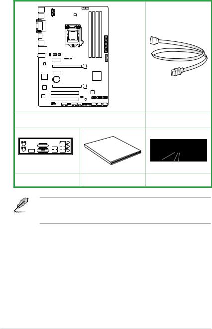
Check your motherboard package for the following items.
|
Z77-A |
|
|
ASUS Z77-A motherboard |
2 x Serial ATA 6.0 Gb/s |
||
cables |
|||
|
|
||
|
Guide |
|
|
|
User |
|
|
1 x I/O Shield |
User Guide |
Support DVD |
|
•If any of the above items is damaged or missing, contact your retailer.
•The illustrated items above are for reference only.Actual product specifications may vary with different models.
xii
Product introduction |
1 |
1.1Product highlights
LGA1155 socket for Intel® 2nd/3rd Generation Core™ i7 / Core™ i5 / Core™ i3, Pentium®, and Celeron® Processors
This motherboard supports Intel 2nd/3rd generation Core™ i7/i5/i3, Pentium®, and Celeron® processors in the LGA1155 package. It provides great graphics and system performance with its GPU, dual-channel DDR3 memory slots, and PCI Express 2.0/3.0 expansion slots.
Intel® Z77 Express Chipset
Intel® Z77 Express Chipset is a single-chipset that supports the 1155 socket Intel® 2nd/3rd generation Core™ i7/i5/ i3, Pentium®, and Celeron® processors. It utilizes the serial point-to- point links, which increases bandwidth and enhances the system’s performance. It natively supports four USB 3.0 ports for up to ten times faster transfer rate than USB 2.0, and enables the iGPU function for Intel® integrated graphics performance.
Dual-Channel DDR3 2400(O.C.)* / 2200(O.C.)* / 2133(O.C) / 1866(O.C.) / 1600 / 1333 / 1066 Support
This motherboard supports DDR3 memory that features data transfer rates of 2400(O.C.)* /
2200(O.C.)* / 2133(O.C.) / 1866(O.C.)/ 1600 / 1333 / 1066 MHz to meet the higher bandwidth requirements of the latest 3D graphics, multimedia, and Internet applications. The dualchannel DDR3 architecture enlarges the bandwidth of your system memory to boost system performance.
Complete USB 3.0 Integration
ASUS facilitates strategic USB 3.0 accessibility for both the front and rear panel - 4 USB 3.0 ports in total. Experience the latest plug & play connectivity at speeds up to 10 times faster than USB 2.0.
Quad-GPU CrossFireX™ Support
This motherboard’s powerful Intel® Z77 platform optimizes PCIe allocation in multiple-GPU
configurations of CrossFireX™. This allows you to enjoy a never before-experienced brand new gaming style.
ASUS Z77-A |
1-1 |

Intel® Smart Response Technology
Intel® Smart Response Technology, an important part of Green ASUS eco-friendly computing, reduces load and wait time, eliminates unecessary hard drive spin thus lowering power usage, and uses an installed SSD (requires 18.6 GB available space) as a cache for frequently accessed data or applications. It combines SSD performance and hard drive capacity, operating up to six times faster than a hard-drive-only system, to boost the system’s overall performance.
*Intel® 2nd/3rd generation Core™ processors on Windows® 7™ operating systems support Intel® Smart Response Technology.
*An operating system must be installed on the HDD to launch Intel® Smart Response Technology.
*The SSD is reserved for caching function.
Intel® Smart Connect Technology
Your computer can receive fresh updates for selected applications, even when the system is in sleep mode. This means less time waiting for applications to update and sync with the cloud, leading to a more efficient computing experience.
Intel® Rapid Start Technology
Intel® Rapid Start Technology allows your system to receive updates for your web applications in real-time even when your system is in sleep mode, saving wait time and power usage.
PCIe 3.0 Ready
PCI Express® 3.0 (PCIe 3.0) is the latest PCI Express bus standard with improved encoding schemes that provide twice the performance of current PCIe 2.0. Total bandwidth for a x16 link reaches a maximum of 32GB/s, double the 16GB/s of PCIe 2.0 (in x16 mode). As such, PCIe 3.0 provides users unprecedented data speeds, combined with the convenience and seamless transition offered by complete backward compatibility with PCIe 1.0 and PCIe 2.0 devices. PCIe 3.0 will become a must-have feature for users who wish to improve and optimize graphic performance, as well as have the latest technology available to them.
PCIe 3.0 speed is supported by Intel® 3rd generation processors.
Gigabit LAN solution
The onboard LAN controller is a highly integrated Gb LAN controller. It is enhanced with an
ACPI management function to provide efficient power management for advanced operating systems.
1-2 |
Chapter 1: Product introduction |
8-channel high definition audio
The onboard 8-channel HD audio (High DefinitionAudio, previously codenamedAzalia) CODEC enables high-quality 192KHz/24-bit audio output and jack-detect feature that automatically detects and identifies what types of peripherals are plugged into the audio I/O jacks and notifies users of inappropriate connection, which means there will be no more confusion of Line-in, Line-out, and Mic jacks.
100% All High-quality Conductive Polymer Capacitors
This motherboard uses all high-quality conductive polymer capacitors for durability, improved lifespan, and enhanced thermal capacity.
ErP ready
This motherboard is European Union´s Energy-related Products (ErP) ready. ErP requires products to meet certain energy efficiency requirements with regard to energy usage.
ASUS Z77-A |
1-3 |
1.2Before you proceed
Take note of the following precautions before you install motherboard components or change any motherboard settings.
• Unplug the power cord from the wall socket before touching any component.
• Before handling components, use a grounded wrist strap or touch a safely grounded object or a metal object, such as the power supply case, to avoid damaging them due to static electricity.
•Hold components by the edges to avoid touching the ICs on them.
•Whenever you uninstall any component, place it on a grounded antistatic pad or in the bag that came with the component.
•Before you install or remove any component, switch off the ATX power supply and detach its power cord. Failure to do so may cause severe damage to the motherboard, peripherals, or components.
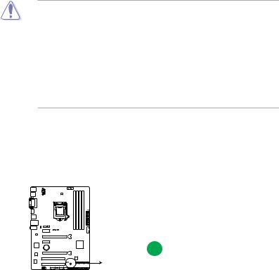
Standby Power LED
The motherboard comes with a standby power LED that lights up to indicate that the system is ON, in sleep mode, or in soft-off mode. This is a reminder that you should shut down
the system and unplug the power cable before removing or plugging in any motherboard component. The illustration below shows the location of the onboard LED.
Z77-A |
SB_PWR |
|
|
ON |
OFF |
|
Standby Power |
Powered Off |
Z77-A Onboard LED
1-4 |
Chapter 1: Product introduction |
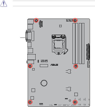
1.3Motherboard overview
1.3.1Placement direction
When installing the motherboard, ensure that you place it into the chassis in the correct orientation. The edge with external ports goes to the rear part of the chassis as indicated in the image below.
1.3.2Screw holes
Place six screws into the holes indicated by circles to secure the motherboard to the chassis.
DO NOT overtighten the screws! Doing so can damage the motherboard.
Place this side towards |
the rear of the chassis. |
Z77-A
|
|
|
|
|
|
|
|
|
|
|
|
|
|
|
|
|
|
|
|
|
|
|
|
|
|
|
|
|
|
|
|
|
|
|
|
|
|
|
|
|
|
|
|
|
|
|
|
|
|
|
|
|
|
|
|
|
|
|
|
|
|
|
|
|
|
|
|
|
|
|
|
|
|
|
|
|
|
|
|
|
|
|
|
|
|
|
|
|
|
|
|
|
|
|
|
|
|
|
|
|
|
|
|
|
|
|
|
|
|
|
|
|
|
|
|
|
|
|
|
|
|
|
|
|
|
|
|
|
|
|
|
|
|
|
|
|
|
|
|
|
|
|
|
|
|
|
|
|
|
|
|
|
|
|
|
|
|
|
|
|
|
|
|
|
|
|
|
|
|
|
|
|
|
|
|
|
|
|
|
|
|
|
|
|
|
|
|
|
|
|
|
|
|
|
|
|
|
|
|
|
|
|
|
|
|
|
|
|
|
|
|
|
|
|
|
|
|
|
|
|
|
|
|
|
|
|
|
|
|
|
|
|
|
|
|
|
|
|
|
|
|
|
|
|
|
|
|
|
|
|
|
|
|
|
|
|
|
|
|
|
|
|
|
|
|
|
|
|
|
|
|
|
|
|
|
|
|
|
|
|
|
|
|
|
|
|
|
|
|
|
|
|
|
|
|
|
|
|
|
|
|
|
|
|
|
|
|
|
|
|
|
|
|
|
|
|
|
|
|
|
|
|
|
|
|
|
|
|
|
|
|
|
|
|
|
|
|
|
|
|
|
|
|
|
|
|
|
|
|
|
|
|
|
|
|
|
|
|
|
|
|
|
|
|
|
|
|
|
|
|
|
|
|
|
|
|
|
|
|
|
|
|
|
|
|
|
|
|
|
|
|
|
|
|
|
|
|
|
|
|
|
|
|
|
|
|
|
|
|
|
|
|
|
|
|
|
|
|
|
|
|
|
|
|
|
|
|
|
|
|
|
|
|
|
|
|
|
|
|
|
|
|
|
|
|
|
|
|
|
|
|
|
|
|
|
|
|
|
|
|
|
|
|
|
|
|
|
|
|
|
|
|
|
|
|
|
|
|
|
|
|
|
|
|
|
|
|
|
|
|
|
|
|
|
|
|
|
|
|
|
|
|
|
|
|
|
|
|
|
|
|
|
|
|
|
|
|
|
|
|
|
|
|
|
|
|
|
|
|
|
|
|
|
|
|
|
|
|
|
|
|
|
|
|
|
|
|
|
|
|
|
|
|
|
|
|
|
|
|
|
|
|
|
|
|
|
|
|
|
|
|
|
|
|
|
|
|
|
|
|
|
|
|
|
|
|
|
|
|
|
|
|
|
|
|
|
|
|
|
|
|
|
|
|
|
|
|
|
|
|
|
|
|
|
|
|
|
|
|
|
|
|
|
|
|
|
|
|
|
|
|
|
|
|
|
|
|
|
|
|
|
|
|
|
|
|
|
|
|
|
|
|
|
|
|
|
|
|
|
|
|
|
|
|
|
|
|
|
|
|
|
|
|
|
|
|
|
|
|
|
|
|
|
|
|
|
|
|
|
|
|
|
|
|
|
|
|
|
|
|
|
|
|
|
|
|
|
|
|
|
|
|
|
|
ASUS Z77-A |
1-5 |
|||||||||||||||||||||||||||||||||||||||||||||||||||||
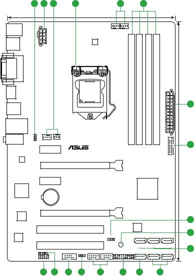
1.3.3Motherboard layout
1 |
2 |
3 |
|
4 |
|
|
3 |
|
5 |
|
|
|
|
|
|
|
|
21.3cm(8.4in) |
|
|
|
|
|
|
|
KBMS |
|
|
|
|
CPU_FAN |
|
|
|
|
|
|
|
|
|
|
|
|
|
CHA_FAN2 |
|
|
|
|
|
|
|
|
|
|
|
|
|
|
|
|
|
|
|
|
|
|
|
|
DIGI |
|
|
|
|
|
|
|
USB34 |
|
|
|
|
+VRM |
|
|
|
|
|
|
|
|
|
|
|
|
|
|
|
|
|
|
|
|
|
EATX12V |
|
|
|
|
|
|
|
|
|
|
|
DVI VGA |
|
|
|
|
|
|
pinmodule) |
pinmodule) |
pinmodule) |
pinmodule) |
|
|
HDMI |
|
|
|
LGA1155 |
|
|
(64bit, 240- |
(64bit, 240- |
(64bit, 240- |
(64bit, 240- |
|
|
USBPWBKB |
|
|
|
|
|
|
A1 |
A2 |
B1 |
B2 |
34 |
30.5cm(12.0in) |
|
|
|
|
|
|
DDR3DIMM |
DDR3DIMM |
DDR3DIMM |
DDR3DIMM |
|||
USB3_12 |
|
|
|
|
|
|
|
|
|
|
|
2 |
|
|
|
|
|
|
|
|
|
|
EATXPWR |
|
|
|
|
|
|
|
|
|
|
|
|
|
|
|
LAN_USB12 |
|
|
|
|
|
|
|
|
|
|
|
|
AUDIO |
CHA_FAN1 PWR_FAN |
|
|
|
|
|
|
|
|
|
||
|
|
|
|
|
|
|
|
|
6 |
|||
|
PCIEX1_1 |
|
|
|
|
|
|
|
|
USB3 |
||
|
|
|
|
|
|
|
|
|
|
|||
|
|
|
|
|
|
|
|
|
|
|
||
RTL |
|
|
Z77-A |
|
|
|
|
|
|
|
||
8111F |
|
|
|
|
|
|
|
|
|
|
|
|
|
|
|
PCIEX16_1 |
|
|
|
|
|
|
|
|
|
|
PCIEX1_2 |
|
|
|
|
|
|
|
|
|
|
|
ASM |
|
|
|
|
|
|
|
|
Intel® |
|
|
|
|
|
|
|
|
|
|
|
Z77 |
|
|
|
|
1083 |
|
|
|
|
|
|
|
|
|
|
|
|
|
BATTERY |
|
|
|
|
|
|
|
|
|
|
|
Super |
|
|
PCIEX16_2 |
|
|
|
|
|
|
|
|
|
|
|
|
|
|
|
|
|
|
|
|
|
|
I/O |
|
|
|
|
|
|
|
|
|
|
|
7 |
|
|
|
|
|
|
|
|
|
|
|
|
|
|
|
|
|
|
|
|
|
8Mb |
|
|
|
|
|
|
|
PCI1 |
|
|
|
|
BIOS |
|
|
|
8 |
ALC |
|
|
|
|
|
USBPWF |
|
|
|
|
|
|
|
|
|
|
|
|
|
|
|
|
|
||
887 |
|
|
|
|
|
|
|
|
|
|
|
|
|
|
|
PCI2 |
|
|
|
|
SATA3G_3 SATA3G_2ZSATA3G_1 |
9 |
|||
SPDIF_OUT |
|
COM |
|
USB78 |
USB56 |
SB_PWR |
|
|
|
|
||
|
CLRTC |
PANEL SATA3G_4 SATA6G_2 SATA6G_1 |
||||||||||
|
|
|
|
|||||||||
|
AAFP |
|
|
|
|
|
|
|
|
|
|
|
|
16 |
15 |
14 |
13 |
|
12 |
11 |
9 |
|
|
10 |
|
1-6 |
Chapter 1: Product introduction |
1.3.4Layout contents
Connectors/Jumpers/Slots/LED |
Page |
|
1. |
Keyboard power (3-pin KB_USBPWB) |
1-23 |
2. |
EATX power connectors (24-pin EATXPWR, 8-pin EATX12V) |
1-27 |
3. |
CPU, Chassis and power fan connectors |
1-26 |
|
(4-pin CPU_FAN, 4-pin CHA_FAN1/2, 3-pin PWR_FAN) |
|
4. |
Intel® CPU socket |
1-7 |
5. |
DDR3 DIMM sockets |
1-11 |
6. |
USB 3.0 connector (20-1 pin USB3_34) |
1-32 |
7. |
USB device wake-up (3-pin USBPWF) |
1-23 |
8. |
Onboard LED (SB_PWR) |
1-4 |
9. |
Intel® Z77 Serial ATA 3.0 Gb/s connectors (7-pin SATA3G_1–4 [blue]) |
1-28 |
10. |
Intel® Z77 Serial ATA 6.0 Gb/s connectors (7-pin SATA6G_1/2 [gray]) |
1-29 |
11. |
System panel connector (20-8 pin F_PANEL) |
1-30 |
12. |
USB 2.0 connectors (10-1 pin USB56, USB78) |
1-32 |
13. |
Clear RTC RAM (3-pin CLRTC) |
1-22 |
14. |
Serial port connectors (10-1 pin COM1) |
1-33 |
15. |
Digital audio connector (4-1 pin SPDIF_OUT) |
1-31 |
16. |
Front panel audio connector (10-1 pin AAFP) |
1-31 |
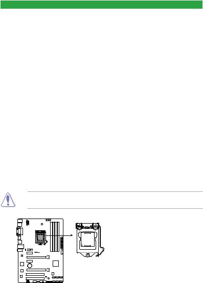
1.4Intel® CPU LGA1155 socket
This motherboard comes with a LGA1155 socket designed for 2nd/3rd generation Core™ i7/i5/i3, Pentium®, and Celeron® processors.
The LGA1156 CPU is incompatible with the LGA1155 socket. DO NOT install a LGA1156 CPU on the LGA1155 socket.
Z77-A
Z77-A CPU socket LGA1155
ASUS Z77-A |
1-7 |

1.4.1CPU installation
The LGA1156 CPU is incompatible with the LGA1155 socket. DO NOT install a LGA1156 CPU on the LGA1155 socket.
1 |
3 |
2
A
4
B
C
A
5
1-8 |
Chapter 1: Product introduction |
1.4.2CPU heatsink and fan assembly installation
Apply the Thermal Interface Material to the CPU heatsink and CPU before you install the heatsink and fan if necessary.
To install the CPU heatsink and fan assembly
1 A B 3
B
A
2 |
4 |
ASUS Z77-A |
1-9 |
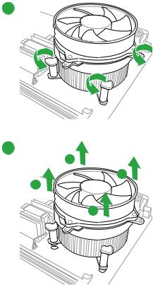
To uninstall the CPU heatsink and fan assembly
1
2
A
B
B
A
1-10 |
Chapter 1: Product introduction |
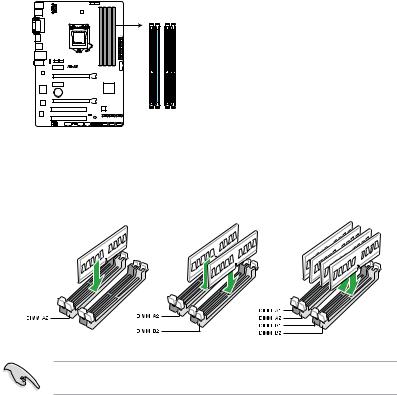
1.5System memory
1.5.1Overview
This motherboard comes with four Double Data Rate 3 (DDR3) Dual Inline Memory Modules (DIMM) sockets.
A DDR3 module has the same physical dimensions as a DDR2 DIMM but is notched differently to prevent installation on a DDR2 DIMM socket. DDR3 modules are developed for better performance with less power consumption.
The figure illustrates the location of the DDR3 DIMM sockets:
DIMM_A1 DIMM_A2
DIMM_B1 DIMM_B2
Z77-A
Z77-A 240-pin DDR3 DIMM sockets
Recommended memory configurations
We recommend that you install the memory modules from the blue slots for better overclocking ability.
ASUS Z77-A |
1-11 |

1.5.2Memory configurations
You may install 1GB, 2GB, 4GB and 8GB unbuffered non ECC DDR3 DIMMs into the DIMM sockets.
•You may install varying memory sizes in ChannelAand Channel B. The system maps the total size of the lower-sized channel for the dual-channel configuration.Any excess memory from the higher-sized channel is then mapped for single-channel operation.
•According to Intel® CPU specifications, DIMM voltage below 1.65V is recommended to protect the CPU.
•Always install DIMMs with the same CAS latency. For optimum compatibility, we recommend that you obtain memory modules from the same vendor.
•Due to the memory address limitation on 32-bit Windows OS, when you install 4GB or more memory on the motherboard, the actual usable memory for the OS can be about 3GB or less. For effective use of memory, we recommend that you do any of the following:
-Use a maximum of 3GB system memory if you are using a 32-bit Windows OS.
-Install a 64-bit Windows OS when you want to install 4GB or more on the motherboard.
-For more details, refer to the Microsoft® support site at http://support.microsoft.com/kb/929605/en-us.
•This motherboard does not support DIMMs made up of 512Mb (64MB) chips or less (Memory chip capacity counts in Megabit, 8 Megabit/Mb = 1 Megabyte/MB).
• The default memory operation frequency is dependent on its Serial Presence Detect (SPD), which is the standard way of accessing information from a memory module. Under the default state, some memory modules for overclocking may operate at a lower frequency than the vendor-marked value. To operate at the vendor-marked
or at a higher frequency, refer to section 2.4 Ai Tweaker menu for manual memory frequency adjustment.
•For system stability, use a more efficient memory cooling system to support a full memory load (4 DIMMs) or overclocking condition.
Visit the ASUS website for the latest QVL.
Z77-A Series Motherboard Qualified Vendors Lists (QVL)
DDR3 2400MHz capability
Vendors |
Part No. |
Size |
SS/DS |
C h i p |
Chip |
Timing |
Voltage |
Brand |
NO. |
||||||
Transcend |
TX2400KLU-4GK (381850)(XMP) |
4GB(2x 2GB) |
SS |
- |
- |
9 |
1.65V |
D I M M s o c k e t s u p p o r t (Optional)
1 DIMM 2 DIMMs 4 DIMMs
••
*The 2400MHz memory modules above are supported on Intel® 3rd generation processors by this motherboard; however, the actual frequency support varied depending on the O.C. margin of the installed CPU.
1-12 |
Chapter 1: Product introduction |

DDR3 2250MHz capability
Vendors |
Part No. |
Size |
S S / |
C h i p |
C h i p |
Timing |
Voltage |
DIMM socket support (Optional) |
||
|
|
|
DS |
Brand |
NO. |
|
|
1 DIMM |
2 DIMMs |
4 DIMMs |
Kingston |
KHX2250C9D3T1K2/4GX(XMP) |
4GB(2x 2GB) |
DS |
- |
- |
- |
1.65V |
• |
• |
• |
*The 2250MHz memory modules above are supported on Intel® 3rd generation processors by this motherboard; however, the actual frequency support varied depending on the O.C. margin of the installed CPU.
DDR3 2200MHz capability
Vendors |
Part No. |
Size |
S S / |
C h i p |
C h i p |
Timing |
Voltage |
DIMM socket support (Optional) |
|
|
|
DS |
Brand |
NO. |
|
|
1 DIMM 2 DIMMs 4 DIMMs |
G.SKILL |
F3-17600CL8D-4GBPS(XMP) |
4GB(2x 2GB) |
DS |
- |
- |
8-8-8-24 |
1.65V |
• |
KINGMAX |
FLKE85F-B8KJAFEIH(XMP) |
4GB(2x 2GB) |
DS |
- |
- |
- |
1.5V-1.7V |
• |
*The 2200MHz memory modules above are supported on Intel® 3rd generation processors by this motherboard; however, the actual frequency support varied depending on the O.C. margin of the installed CPU.
DDR3 2133MHz capability
Vendors |
Part No. |
Size |
S S / |
C h i p |
Chip |
Timing |
Voltage |
DIMM socket support (Optional) |
||
DS |
Brand |
NO. |
1 DIMM |
2 DIMMs |
4 DIMMs |
|||||
|
|
|
|
|
|
|
|
|||
A-DATA |
AX3U2133GC2G9B-DG2(XMP) |
2GB |
SS |
- |
- |
9-11-9-27 |
1.55~1.75V |
• |
|
|
CORSAIR |
CMT4GX3M2A2133C9(XMP) |
4GB(2x 2GB) |
DS |
- |
- |
9-10-9-24 |
1.65V |
• |
|
|
CORSAIR |
CMT4GX3M2B2133C9(XMP) |
4GB(2x 2GB) |
DS |
- |
- |
9-10-9-27 |
1.50V |
• |
• |
|
GEIL |
GE34GB2133C9DC(XMP) |
2GB |
DS |
- |
- |
9-9-9-28 |
1.65V |
• |
• |
|
GEIL |
GU34GB2133C9DC(XMP) |
4GB(2 x 2GB) |
DS |
- |
- |
9-9-9-28 |
1.65V |
• |
• |
• |
KINGSTON |
KHX2133C9AD3T1K2/4GX(XMP) |
4GB(2x 2GB ) |
DS |
- |
- |
- |
1.65V |
• |
• |
• |
KINGSTON |
KHX2133C9AD3X2K2/4GX(XMP) |
4GB(2 x 2GB) |
DS |
- |
- |
9-11-9-27 |
1.65V |
• |
• |
• |
KINGSTON |
KHX2133C9AD3T1K4/8GX(XMP) |
8GB(4 x 2GB) |
DS |
- |
- |
9-11-9-27 |
1.65V |
• |
• |
• |
KINGSTON |
KHX2133C9AD3T1FK4/8GX(XMP) |
8GB(4x 2GB) |
DS |
- |
- |
- |
1.65V |
• |
• |
• |
DDR3 2000MHz capability
Vendors |
Part No. |
Size |
S S / C h i p |
Chip |
Timing |
Voltage |
DIMM socket support (Optional) |
|||
DS |
Brand |
NO. |
1 DIMM |
2 DIMMs |
4 DIMMs |
|||||
Apacer |
78.AAGD5.9KD(XMP) |
6GB(3 x 2GB) |
DS |
- |
- |
9-9-9-27 |
1.65V |
• |
• |
• |
CORSAIR |
CMZ4GX3M2A2000C10(XMP) |
4GB(2 x 2GB) |
SS |
- |
- |
10-10-10-27 |
1.50V |
• |
• |
• |
CORSAIR |
CMT6GX3M3A2000C8(XMP) |
6GB(3 x 2GB) |
DS |
- |
- |
8-9-8-24 |
1.65V |
• |
• |
|
G.SKILL |
F3-16000CL9D-4GBFLS(XMP) |
4GB(2 x 2GB) |
DS |
- |
- |
9-9-9-24 |
1.65V |
• |
• |
• |
G.SKILL |
F3-16000CL9D-4GBTD(XMP) |
4GB(2 x 2GB) |
DS |
- |
- |
9-9-9-27 |
1.65V |
• |
• |
• |
G.SKILL |
F3-16000CL6T-6GBPIS(XMP) |
6GB(3x 2GB ) |
DS |
- |
- |
6-9-6-24 |
1.65V |
• |
• |
|
GEIL |
GUP34GB2000C9DC(XMP) |
4GB(2 x 2GB) |
DS |
- |
- |
9-9-9-28 |
1.65V |
|
|
|
KINGSTON |
KHX2000C9AD3T1K2/ |
4GB(2x 2GB ) |
DS |
- |
- |
- |
1.65V |
• |
• |
• |
4GX(XMP) |
||||||||||
KINGSTON |
KHX2000C9AD3W1K2/ |
4GB(2x 2GB ) |
DS |
- |
- |
- |
1.65V |
• |
• |
|
4GX(XMP) |
|
|||||||||
KINGSTON |
KHX2000C9AD3T1K2/ |
4GB(2 x 2GB) |
DS |
- |
- |
9 |
1.65V |
• |
• |
• |
4GX(XMP) |
||||||||||
KINGSTON |
KHX2000C9AD3W1K3/ |
6GB(3x 2GB ) |
DS |
- |
- |
- |
1.65V |
• |
• |
|
6GX(XMP) |
|
|||||||||
KINGSTON |
KHX2000C9AD3T1K3/ |
6GB(3x 2GB ) |
DS |
- |
- |
- |
1.65V |
• |
• |
|
6GX(XMP) |
|
|||||||||
Transcend |
TX2000KLN-8GK(XMP) |
8GB(2 x 4GB) |
DS |
- |
- |
- |
1.6V |
• |
• |
• |
ASUS Z77-A |
1-13 |

DDR3 1866MHz capability
Vendors |
Part No. |
Size |
S S / |
C h i p |
Chip |
Timing |
Voltage |
DIMM socket support (Optional) |
|||
|
|
|
DS |
Brand |
NO. |
|
|
1 DIMM |
2 DIMMs |
4 DIMMs |
|
CORSAIR |
CMT4GX3M2A1866C9(XMP) |
4GB(2 x 2GB) |
DS |
- |
- |
9-9-9-24 |
1.65V |
• |
• |
• |
|
CORSAIR |
CMT6GX3MA1866C9(XMP) |
6GB(3 x 2GB) |
DS |
- |
- |
9-9-9-24 |
1.65V |
• |
• |
|
|
CORSAIR |
CMZ8GX3M2A1866C9(XMP) |
8GB(2 x 4GB) |
DS |
- |
- |
9-10-9-27 |
1.50V |
• |
• |
• |
|
G.SKILL |
F3-14900CL9D- |
8GB(2 x 4GB) |
DS |
- |
- |
9-10-9-28 |
1.5V |
• |
• |
• |
|
8GBXL(XMP) |
|||||||||||
|
|
|
|
|
|
|
|
|
|
||
G.SKILL |
F3-14900CL9Q- |
8GB(2GB x 4) |
DS |
- |
- |
9-9-9-24 |
1.6V |
• |
• |
• |
|
8GBXL(XMP) |
|||||||||||
|
|
|
|
|
|
|
|
|
|
||
KINGSTON |
KHX1866C9D3T1K3/ |
3GB(3 x 1GB) |
SS |
- |
- |
- |
1.65V |
• |
• |
• |
|
3GX(XMP) |
|||||||||||
|
|
|
|
|
|
|
|
|
|
||
KINGSTON |
KHX1866C9D3T1K3/ |
6GB(3 x 2GB) |
DS |
- |
- |
- |
1.65V |
• |
• |
• |
|
6GX(XMP) |
|||||||||||
|
|
|
|
|
|
|
|
|
|
||
DDR3 1600MHz capability
Vendors |
Part No. |
Size |
SS/ |
C h i |
p Chip NO. |
Timing |
Voltage |
D I M M s o c k e t s u p p o r t |
|||
(Optional) |
|
||||||||||
|
|
|
DS |
Brand |
|
|
|
1 DIMM |
2 DIMMs |
4 DIMMs |
|
|
|
|
|
|
|
|
|
||||
A-DATA |
AM2U16BC2P1 |
2GB |
SS |
A-DATA |
3CCD-150 |
- |
- |
• |
• |
• |
|
9A EL1126T |
|||||||||||
A-DATA |
AD31600E001GM(O)U3K |
3GB(3 x 1GB) |
SS |
- |
- |
8-8-8-24 |
1.65V- |
• |
• |
|
|
1.85V |
|
||||||||||
|
|
|
|
|
|
|
|
|
|
||
A-DATA |
AM2U16BC4P2 |
4GB |
DS |
A-DATA |
3CCD-150 |
- |
- |
• |
• |
• |
|
9A EL1126T |
|||||||||||
A-DATA |
AX3U1600GC4G9-2G(XMP) |
8GB(2 x 4GB) |
DS |
- |
- |
9-9-9-24 |
1.55V- |
• |
• |
• |
|
1.75V |
|||||||||||
|
|
|
|
|
|
|
|
|
|
||
A-DATA |
AX3U1600XC4G79-2X(XMP) |
8GB(2 x 4GB) |
DS |
- |
- |
7-9-7-21 |
1.55V- |
• |
• |
• |
|
1.75V |
|||||||||||
|
|
|
|
|
|
|
|
|
|
||
CORSAIR |
TR3X3G1600C8D(XMP) |
3GB(3 x 1GB) |
SS |
- |
- |
8-8-8-24 |
1.65V |
• |
• |
|
|
CORSAIR |
CMD12GX3M6A1600C8(XMP) |
12GB(6x2GB) |
DS |
- |
- |
8-8-8-24 |
1.65V |
• |
• |
• |
|
CORSAIR |
CMP4GX3M2A1600C8(XMP) |
4GB(2 x 2GB) |
DS |
- |
- |
8-8-8-24 |
1.65V |
• |
• |
• |
|
CORSAIR |
CMP4GX3M2A1600C9(XMP) |
4GB(2 x 2GB) |
DS |
- |
- |
9-9-9-24 |
1.65V |
• |
• |
• |
|
CORSAIR |
CMP4GX3M2C1600C7(XMP) |
4GB(2 x 2GB) |
DS |
- |
- |
7-8-7-20 |
1.65V |
• |
• |
• |
|
CORSAIR |
CMX4GX3M2A1600C9(XMP) |
4GB(2 x 2GB) |
DS |
- |
- |
9-9-9-24 |
1.65V |
• |
• |
|
|
CORSAIR |
CMX4GX3M2A1600C9(XMP) |
4GB(2 x 2GB) |
DS |
- |
- |
9-9-9-24 |
1.65V |
• |
• |
• |
|
CORSAIR |
TR3X6G1600C8 G(XMP) |
6GB(3 x 2GB) |
DS |
- |
- |
8-8-8-24 |
1.65V |
• |
• |
• |
|
CORSAIR |
TR3X6G1600C8D G(XMP) |
6GB(3 x 2GB) |
DS |
- |
- |
8-8-8-24 |
1.65V |
• |
• |
• |
|
CORSAIR |
TR3X6G1600C9 G(XMP) |
6GB(3 x 2GB) |
DS |
- |
- |
9-9-9-24 |
1.65V |
• |
• |
• |
|
CORSAIR |
CMP8GX3M2A1600C9(XMP) |
8GB(2 x 4GB) |
DS |
- |
- |
9-9-9-24 |
1.65V |
• |
• |
• |
|
CORSAIR |
CMZ8GX3M2A1600C7R(XMP) |
8GB(2 x 4GB) |
DS |
- |
- |
7-8-7-20 |
1.50V |
• |
• |
• |
|
CORSAIR |
CMX8GX3M4A1600C9(XMP) |
8GB(4 x 2GB) |
DS |
- |
- |
9-9-9-24 |
1.65V |
• |
• |
• |
|
Crucial |
BL25664BN1608.16FF(XMP) |
6GB(3 x 2GB) |
DS |
- |
- |
- |
- |
• |
• |
• |
|
G.SKILL |
F3-12800CL9D-2GBNQ(XMP) |
2GB(2 x 1GB) |
SS |
- |
- |
9-9-9-24 |
1.5V |
• |
• |
• |
|
G.SKILL |
F3-12800CL7D-4GBRH(XMP) |
4GB(2 x 2GB) |
SS |
- |
- |
7-7-7-24 |
1.6V |
• |
• |
• |
|
G.SKILL |
F3-12800CL7D-4GBRM(XMP) |
4GB(2 x 2GB) |
DS |
- |
- |
7-8-7-24 |
1.6V |
• |
• |
• |
|
G.SKILL |
F3-12800CL8D-4GBRM(XMP) |
4GB(2 x 2GB) |
DS |
- |
- |
8-8-8-24 |
1.60V |
• |
• |
• |
|
G.SKILL |
F3-12800CL9D-4GBECO(XMP) |
4GB(2 x 2GB) |
DS |
- |
- |
9-9-9-24 |
XMP 1.35V |
• |
• |
• |
|
G.SKILL |
F3-12800CL9D-4GBRL(XMP) |
4GB(2 x 2GB) |
DS |
- |
- |
9-9-9-24 |
1.5V |
• |
• |
• |
|
G.SKILL |
F3-12800CL9T-6GBNQ(XMP) |
6GB(3 x 2GB) |
DS |
- |
- |
9-9-9-24 |
1.5V~1.6V |
• |
• |
• |
|
G.SKILL |
F3-12800CL7D-8GBRH(XMP) |
8GB(2 x 4GB) |
DS |
- |
- |
7-8-7-24 |
1.6V |
• |
• |
• |
|
G.SKILL |
F3-12800CL8D-8GBECO(XMP) |
8GB(2 x 4GB) |
DS |
- |
- |
8-8-8-24 |
XMP 1.35V |
• |
• |
• |
|
G.SKILL |
F3-12800CL9D-8GBRL(XMP) |
8GB(2 x 4GB) |
DS |
- |
- |
9-9-9-24 |
1.5V |
• |
• |
• |
|
GEIL |
GET316GB1600C9QC(XMP) |
16GB(4x |
DS |
- |
- |
9-9-9-28 |
1.6V |
• |
• |
• |
|
4GB) |
|||||||||||
|
|
|
|
|
|
|
|
|
|
||
GEIL |
GV34GB1600C8DC(XMP) |
2GB |
DS |
- |
- |
8-8-8-28 |
1.6V |
• |
• |
• |
|
KINGMAX |
FLGD45F-B8MF7 MAEH(XMP) |
1GB |
SS |
- |
- |
7 |
- |
• |
• |
|
|
KINGMAX |
FLGE85F-B8KJ9A FEIS(XMP) |
2GB |
DS |
- |
- |
- |
- |
• |
• |
• |
|
KINGMAX |
FLGE85F-B8MF7 MEEH(XMP) |
2GB |
DS |
- |
- |
7 |
- |
• |
|
|
|
KINGSTON |
KHX1600C9D3P1K2/4G |
4GB(2 x 2GB) |
SS |
- |
- |
- |
1.5V |
• |
• |
• |
|
KINGSTON |
KHX1600C9D3K3/12GX(XMP) |
12GB(3x4GB) |
DS |
- |
- |
9-9-9-27 |
1.65V |
• |
• |
• |
|
1-14 |
Chapter 1: Product introduction |

DDR3 1600MHz capability
Vendors |
Part No. |
Size |
SS/ |
C h i p |
Chip NO. |
Timing |
Voltage |
D I M M s o c k e t s u p p o r t |
|||
(Optional) |
|
||||||||||
|
|
|
DS |
Brand |
|
|
|
1 DIMM |
2 DIMMs |
4 DIMMs |
|
|
|
|
|
|
|
|
|
||||
KINGSTON |
KHX1600C9D3T1BK3/ |
12GB(3x4GB) |
DS |
- |
- |
9-9-9-27 |
1.65V |
• |
• |
• |
|
12GX(XMP) |
|||||||||||
|
|
|
|
|
|
|
|
|
|
||
KINGSTON |
KHX1600C9AD3/2G |
2GB |
DS |
- |
- |
- |
1.65V |
• |
• |
• |
|
KINGSTON |
KVR1600D3N11/2G-ES |
2GB |
DS |
KTC |
D1288JPN |
11-11- |
1.35V-1.5V |
• |
• |
• |
|
DPLD9U |
11-28 |
||||||||||
|
|
|
|
|
|
|
|
|
|||
KINGSTON |
KHX1600C7D3K2/4GX(XMP) |
4GB(2x 2GB ) |
DS |
- |
- |
- |
1.65V |
• |
• |
• |
|
KINGSTON |
KHX1600C8D3K2/4GX(XMP) |
4GB(2 x 2GB) |
DS |
- |
- |
8 |
1.65V |
• |
• |
• |
|
KINGSTON |
KHX1600C8D3T1K2/4GX(XMP) |
4GB(2 x 2GB) |
DS |
- |
- |
8 |
1.65V |
• |
• |
• |
|
KINGSTON |
KHX1600C9D3K2/4GX(XMP) |
4GB(2 x 2GB) |
DS |
- |
- |
9 |
1.65V |
• |
• |
• |
|
KINGSTON |
KHX1600C9D3LK2/4GX(XMP) |
4GB(2 x 2GB) |
DS |
- |
- |
9 |
XMP 1.35V |
• |
• |
• |
|
KINGSTON |
KHX1600C9D3X2K2/4GX(XMP) |
4GB(2 x 2GB) |
DS |
- |
- |
9-9-9-27 |
1.65V |
• |
• |
• |
|
KINGSTON |
KHX1600C9D3T1K3/6GX(XMP) |
6GB(3x 2GB ) |
DS |
- |
- |
- |
1.65V |
• |
• |
• |
|
KINGSTON |
KHX1600C9D3K3/6GX(XMP) |
6GB(3 x 2GB) |
DS |
- |
- |
9 |
1.65V |
• |
• |
• |
|
KINGSTON |
KHX1600C9D3T1BK3/6GX |
6GB(3 x 2GB) |
DS |
- |
- |
9-9-9-27 |
1.65V |
• |
• |
• |
|
(XMP) |
|||||||||||
|
|
|
|
|
|
|
|
|
|
||
KINGSTON |
KHX1600C9D3K2/8GX(XMP) |
8GB(2 x 4GB) |
DS |
- |
- |
9-9-9-27 |
1.65V |
• |
• |
• |
|
KINGSTON |
KHX1600C9D3P1K2/8G |
8GB(2 x 4GB) |
DS |
- |
- |
- |
1.5V |
• |
• |
• |
|
Super Talent |
WA160UX6G9 |
6GB(3 x 2GB) |
DS |
- |
- |
9 |
- |
• |
• |
|
|
Transcend |
JM1600KLN-8GK |
8GB(4GBx2) |
DS |
Transcend |
TK483 |
- |
- |
• |
• |
• |
|
PCW3 |
|||||||||||
Asint |
SLZ3128M8-EGJ1D(XMP) |
2GB |
DS |
Asint |
3128M8 |
9-9-9-24 |
1.6V |
• |
• |
• |
|
-GJ1D |
|||||||||||
|
|
|
|
|
|
|
|
|
|
||
Elixir |
M2P2G64CB8HC9N-DG(XMP) |
2GB |
DS |
- |
- |
- |
- |
• |
• |
• |
|
Mushkin |
998659(XMP) |
6GB(3 x 2GB) |
DS |
- |
- |
9-9-9-24 |
1.5~1.6V |
• |
• |
• |
|
DDR3 1333MHz capability
Vendors |
Part No. |
Size |
S S / |
Chip Brand |
Chip NO. |
Timing |
Voltage |
D I M M s o c k e t s u p p o r t |
|||
(Optional) |
|
||||||||||
|
|
|
DS |
|
|
|
|
1 DIMM |
2 DIMMs |
4 DIMMs |
|
A-DATA |
AD31333001GOU |
1GB |
SS |
A-Data |
AD30908C8D-151C |
- |
- |
• |
• |
• |
|
E0906 |
|||||||||||
|
|
|
|
|
|
|
|
|
|
||
A-DATA |
AD3U1333C2G9 |
2GB |
SS |
A-DATA |
3CCD-1509HNA1126L |
- |
- |
• |
• |
• |
|
A-DATA |
AD63I1B0823EV |
2GB |
SS |
A-Data |
3CCA-1509A |
- |
- |
• |
• |
• |
|
A-DATA |
AM2U139C2P1 |
2GB |
SS |
ADATA |
3CCD-1509A EL1127T |
- |
- |
• |
• |
• |
|
A-DATA |
AX3U1333C2G9-BP |
2GB |
SS |
- |
- |
- |
- |
• |
• |
• |
|
A-DATA |
AD31333G001GOU |
3GB |
SS |
- |
- |
8-8-8-24 |
1.65- |
• |
• |
• |
|
(3 x 1GB) |
1.85V |
||||||||||
|
AXDU1333GC2 |
4GB |
|
|
|
|
1.25V- |
|
|
|
|
A-DATA |
SS |
- |
- |
9-9-9-24 |
1.35V(low |
• |
• |
• |
|||
G9-2G(XMP) |
(2 x 2GB) |
||||||||||
|
|
|
|
|
voltage) |
|
|
|
|||
|
|
|
|
|
|
|
|
|
|
||
A-DATA |
AD31333G002GMU |
2GB |
DS |
- |
- |
8-8-8-24 |
1.65- |
• |
• |
|
|
1.85V |
|
||||||||||
A-DATA |
AD63I1C1624EV |
4GB |
DS |
A-Data |
3CCA-1509A |
- |
- |
• |
• |
• |
|
A-DATA |
AM2U139C4P2 |
4GB |
DS |
ADATA |
3CCD-1509A EL1127T |
- |
- |
• |
• |
• |
|
A-DATA |
SU3U1333W8G9-B |
8GB |
DS |
ELPIDA |
J4208BASE-DJ-F |
- |
- |
• |
|
|
|
Apacer |
78.A1GC6.9L1 |
2GB |
DS |
Apacer |
AM5D5808DEWSBG |
- |
- |
• |
• |
• |
|
Apacer |
78.A1GC6.9L1 |
2GB |
DS |
Apacer |
AM5D5808FEQSBG |
9 |
- |
• |
• |
• |
|
Apacer |
AU02GFA33C9NBGC |
2GB |
DS |
Apacer |
AM5D5808APQSBG |
- |
- |
• |
• |
• |
|
Apacer |
78.B1GDE.9L10C |
4GB |
DS |
Apacer |
AM5D5908CEHSBG |
- |
- |
• |
• |
• |
|
CORSAIR |
CM3X1024-1333C9 |
1GB |
SS |
- |
- |
9-9-9-24 |
1.60V |
• |
• |
• |
|
CORSAIR |
TR3X3G1333C9 G |
3GB |
SS |
- |
- |
9-9-9-24 |
1.50V |
• |
• |
• |
|
(3 x 1GB) |
|||||||||||
|
|
|
|
|
|
|
|
|
|
||
CORSAIR |
TR3X6G1333C9 G |
6GB |
SS |
- |
- |
9-9-9-24 |
1.50V |
• |
• |
|
|
(3x 2GB) |
|
||||||||||
|
|
|
|
|
|
|
|
|
|
||
CORSAIR |
CMD24GX3M6A |
24GB |
DS |
- |
- |
9-9-9-24 |
1.60V |
• |
• |
• |
|
1333C9(XMP) |
(6 x 4GB) |
||||||||||
|
|
|
|
|
|
|
|
|
|||
CORSAIR |
TW3X4G1333C9D G |
4GB |
DS |
- |
- |
9-9-9-24 |
1.50V |
• |
• |
• |
|
(2 x 2GB) |
|||||||||||
|
|
|
|
|
|
|
|
|
|
||
CORSAIR |
CM3X4GA1333C9N2 |
4GB |
DS |
CORSAIR |
256MBDCJ |
9-9-9-24 |
- |
• |
• |
• |
|
GELC0401136 |
|||||||||||
|
|
|
|
|
|
|
|
|
|
||
CORSAIR |
CMX4GX3M1A1333C9 |
4GB |
DS |
- |
- |
9-9-9-24 |
1.50V |
• |
• |
• |
|
CORSAIR |
CMD8GX3M4A1333C7 |
8GB |
DS |
- |
- |
7-7-7-20 |
1.60V |
• |
• |
• |
|
(4 x 2GB) |
|||||||||||
|
|
|
|
|
|
|
|
|
|
||
ASUS Z77-A |
1-15 |

Vendors |
Part No. |
Size |
S S / |
Chip Brand |
Chip NO. |
Timing |
Voltage |
D I M M s o c k e t s u p p o r t |
|||
(Optional) |
|
||||||||||
|
|
|
DS |
|
|
|
|
1 DIMM |
2 DIMMs |
4 DIMMs |
|
|
|
|
|
|
|
|
|
||||
Crucial |
CT12864BA1339.8FF |
1GB |
SS |
Micron |
9FF22D9KPT |
9 |
- |
• |
• |
• |
|
Crucial |
CT25664BA1339.16FF |
2GB |
DS |
Micron |
9KF27D9KPT |
9 |
- |
• |
• |
• |
|
Crucial |
BL25664BN13 |
6GB |
DS |
- |
- |
7-7-7-24 |
1.65V |
• |
• |
• |
|
37.16FF (XMP) |
(3 x 2GB) |
||||||||||
|
|
|
|
|
|
|
|
|
|||
ELPIDA |
EBJ10UE8EDF0-DJ-F |
1GB |
SS |
ELPIDA |
J1108EDSE-DJ-F |
- |
1.35V(low |
• |
• |
• |
|
voltage) |
|||||||||||
|
|
|
|
|
|
|
|
|
|
||
ELPIDA |
EBJ21UE8EDF0-DJ-F |
2GB |
DS |
ELPIDA |
J1108EDSE-DJ-F |
- |
1.35V(low |
• |
• |
|
|
voltage) |
|
||||||||||
|
|
|
|
|
|
|
|
|
|
||
G.SKILL |
F3-10600CL8 |
1GB |
SS |
G.SKILL |
- |
- |
- |
• |
• |
• |
|
D-2GBHK(XMP) |
|||||||||||
|
|
|
|
|
|
|
|
|
|
||
G.SKILL |
F3-10600CL |
2GB |
SS |
- |
- |
9-9-9-24 |
1.5V |
• |
• |
• |
|
9D-2GBNQ |
(2 x 1GB) |
||||||||||
|
|
|
|
|
|
|
|
|
|||
G.SKILL |
F3-10666CL7 |
3GB |
SS |
- |
- |
7-7-7-18 |
1.5~1.6V |
• |
• |
• |
|
T-3GBPK(XMP) |
(3 x 1GB) |
||||||||||
|
|
|
|
|
|
|
|
|
|||
G.SKILL |
F3-10666CL8D- |
4GB |
DS |
- |
- |
8-8-8- |
XMP |
• |
• |
• |
|
4GBECO(XMP) |
(2 x 2GB) |
8-24 |
1.35V |
||||||||
|
|
|
|
|
|
|
|||||
G.SKILL |
F3-10666CL |
6GB |
DS |
- |
- |
7-7-7-18 |
1.5~1.6V |
• |
• |
|
|
7T-6GBPK(XMP) |
(3 x 2GB) |
|
|||||||||
|
|
|
|
|
|
|
|
|
|||
G.SKILL |
F3-10666C |
8GB |
DS |
- |
- |
7-7-7-21 |
1.5V |
• |
• |
• |
|
L7D-8GBRH(XMP) |
(2 x 4GB) |
||||||||||
|
|
|
|
|
|
|
|
|
|||
GEIL |
GET316GB1333C9QC |
16GB |
DS |
- |
- |
9-9-9-24 |
1.5V |
• |
|
|
|
(4 x 4GB) |
|
|
|||||||||
|
|
|
|
|
|
|
|
|
|
||
GEIL |
GV32GB1333C9DC |
2GB |
DS |
- |
- |
9-9-9-24 |
1.5V |
• |
• |
• |
|
(2 x 1GB) |
|||||||||||
|
|
|
|
|
|
|
|
|
|
||
GEIL |
GG34GB1333C9DC |
4GB |
DS |
GEIL |
GL1L128M88BA12N |
9-9-9-24 |
1.3V(low |
• |
• |
• |
|
(2 x 2GB) |
voltage) |
||||||||||
GEIL |
GV34GB1333C9DC |
4GB |
DS |
- |
- |
9-9-9-24 |
1.5V |
• |
• |
• |
|
(2 x 2GB) |
|||||||||||
|
|
|
|
|
|
|
|
|
|
||
GEIL |
GVP34GB1333C7DC |
4GB |
DS |
- |
- |
7-7-7-24 |
1.5V |
• |
• |
• |
|
(2 x 2GB) |
|||||||||||
|
|
|
|
|
|
|
|
|
|
||
Hynix |
HMT112U6TFR8A-H9 |
1GB |
SS |
Hynix |
H5TC1G83TFRH9A |
- |
1.35V(low |
• |
• |
• |
|
voltage) |
|||||||||||
|
|
|
|
|
|
|
|
|
|
||
Hynix |
HMT325U6BFR8C-H9 |
2GB |
SS |
Hynix |
H5TQ2G83BFRH9C |
- |
- |
• |
• |
• |
|
Hynix |
HMT125U6TFR8A-H9 |
2GB |
DS |
Hynix |
H5TC1G83TFRH9A |
- |
1.35V(low |
• |
• |
• |
|
voltage) |
|||||||||||
|
|
|
|
|
|
|
|
|
|
||
Hynix |
HMT351U6BFR8C-H9 |
4GB |
DS |
Hynix |
H5TQ2G83BFRH9C |
- |
- |
• |
• |
• |
|
KINGMAX |
FLFD45F-B8KL9 NAES |
1GB |
SS |
KINGMAX |
KKB8FNWBFGNX-27A |
- |
- |
• |
• |
• |
|
KINGMAX |
FLFE85F-C8KF9 CAES |
2GB |
SS |
KINGMAX |
KFC8FMFXF-DXX-15A |
- |
- |
• |
• |
• |
|
KINGMAX |
FLFE85F-C8KL9 NAES |
2GB |
SS |
KINGMAX |
KFC8FNLXF-DXX-15A |
- |
- |
• |
• |
• |
|
KINGMAX |
FLFE85F-C8KM9 NAES |
2GB |
SS |
KINGMAX |
KFC8FNMXF-BXX-15A |
- |
- |
• |
• |
• |
|
KINGMAX |
FLFE85F-B8KL9 NEES |
2GB |
DS |
KINGMAX |
KKB8FNWBFGNX-26A |
- |
- |
• |
• |
• |
|
KINGMAX |
FLFF65F-C8KL9 NEES |
4GB |
DS |
KINGMAX |
KFC8FNLXF-DXX-15A |
- |
- |
• |
• |
• |
|
KINGMAX |
FLFF65F-C8KM9 NEES |
4GB |
DS |
KINGMAX |
KFC8FNMXF-BXX-15A |
- |
- |
• |
• |
• |
|
KINGSTON |
KVR1333D3 |
1GB |
SS |
ELPIDA |
J1108BDBG-DJ-F |
9 |
1.5V |
• |
• |
• |
|
N9/1G(low profile) |
|||||||||||
KINGSTON |
KVR1333D3 |
2GB |
SS |
Hynix |
H5TQ2G83AFRH9C |
9 |
- |
• |
• |
• |
|
N9/2G(low profile) |
|||||||||||
KINGSTON |
KVR1333D3S8N9/2G |
2GB |
SS |
Micron |
IID77 D9LGK |
- |
1.5V |
• |
• |
• |
|
KINGSTON |
KVR1333D3S |
2GB |
SS |
ELPIDA |
J2108BCSE-DJ-F |
- |
1.5V |
• |
• |
• |
|
8N9/2G-SP(low profile) |
|||||||||||
KINGSTON |
KVR1333D3 |
2GB |
DS |
ELPIDA |
J1108BFBG-DJ-F |
9 |
1.5V |
• |
• |
• |
|
N9/2G(low profile) |
|||||||||||
KINGSTON |
KVR1333D3N9/2G |
2GB |
DS |
KTC |
D1288JPNDPLD9U |
9 |
1.5V |
• |
• |
• |
|
KINGSTON |
KVR1333D3N9/2G |
2GB |
DS |
ELPIDA |
J1108BDSE-DJ-F |
9 |
1.5V |
• |
• |
• |
|
KINGSTON |
KVR1333D3 |
2GB |
DS |
KTC |
D1288JEMFNGD9U |
- |
1.5V |
• |
• |
• |
|
N9/2G-SP(low profile) |
|||||||||||
KINGSTON |
KVR1333D3N9/2G- |
2GB |
DS |
KINGSTON |
D1288JPSFPGD9U |
- |
1.5V |
• |
• |
• |
|
SP(low profile) |
|||||||||||
KINGSTON |
KHX1333C7 |
4GB |
DS |
- |
- |
7 |
1.65V |
• |
• |
• |
|
D3K2/4GX(XMP) |
(2 x 2GB) |
||||||||||
|
|
|
|
|
|
|
|
|
|||
KINGSTON |
KHX1333C9D3UK2/ |
4GB |
DS |
- |
- |
9 |
XMP |
• |
|
|
|
4GX(XMP) |
(2 x 2GB) |
1.25V |
|
|
|||||||
|
|
|
|
|
|
|
|
||||
KINGSTON |
KVR1333D |
4GB |
DS |
ELPIDA |
J2108BCSE-DJ-F |
9 |
1.5V |
• |
• |
• |
|
3N9/4G(low profile) |
|||||||||||
KINGSTON |
KVR1333D |
4GB |
DS |
ELPIDA |
J2108BCSE-DJ-F |
- |
1.5V |
• |
• |
• |
|
3N9/4G(low profile) |
|||||||||||
KINGSTON |
KVR1333D3N9/4G |
4GB |
DS |
KTC |
D2568JENCNGD9U |
- |
1.5V |
• |
• |
• |
|
KINGSTON |
KVR1333D3N9/4G |
4GB |
DS |
Hynix |
H5TQ2G83AFR |
- |
- |
• |
• |
• |
|
KINGSTON |
KVR1333D3N9/4G- |
4GB |
DS |
KINGSTON |
D2568JENCPGD9U |
- |
1.5V |
• |
• |
• |
|
SP(low profile) |
|||||||||||
Micron |
MT4JTF12864AZ- |
1GB |
SS |
Micron |
OJD12D9LGQ |
- |
- |
• |
• |
• |
|
1G4D1 |
|||||||||||
|
|
|
|
|
|
|
|
|
|
||
Micron |
MT8JTF12864AZ- |
1GB |
SS |
Micron |
9FF22D9KPT |
9 |
- |
• |
• |
• |
|
1G4F1 |
|||||||||||
|
|
|
|
|
|
|
|
|
|
||
1-16 |
Chapter 1: Product introduction |
 Loading...