


X99-A II
<![endif]>Motherboard

E11090
First Edition
April 2016
Copyright© 2016 ASUSTeK COMPUTER INC. All Rights Reserved.
No part of this manual, including the products and software described in it, may be reproduced, transmitted, transcribed, stored in a retrieval system, or translated into any language in any form or by any means, except documentation kept by the purchaser for backup purposes, without the express written permission of ASUSTeK COMPUTER INC. (“ASUS”).
Product warranty or service will not be extended if: (1) the product is repaired, modified or altered, unless such repair, modification of alteration is authorized in writing by ASUS; or (2) the serial number of the product is defaced or missing.
ASUS PROVIDES THIS MANUAL “AS IS” WITHOUT WARRANTY OF ANY KIND, EITHER EXPRESS OR IMPLIED, INCLUDING BUT NOT LIMITED TO THE IMPLIED WARRANTIES OR CONDITIONS OF MERCHANTABILITY OR FITNESS FOR A PARTICULAR PURPOSE. IN NO EVENT SHALL ASUS, ITS DIRECTORS, OFFICERS, EMPLOYEES OR AGENTS BE LIABLE FOR ANY INDIRECT, SPECIAL, INCIDENTAL, OR CONSEQUENTIAL DAMAGES (INCLUDING DAMAGES FOR LOSS OF PROFITS, LOSS OF BUSINESS, LOSS OF USE OR DATA, INTERRUPTION OF BUSINESS AND THE LIKE), EVEN IF ASUS HAS BEEN ADVISED OF THE POSSIBILITY OF SUCH DAMAGES ARISING FROM ANY DEFECT OR ERROR IN THIS MANUAL OR PRODUCT.
SPECIFICATIONS AND INFORMATION CONTAINED IN THIS MANUAL ARE FURNISHED FOR INFORMATIONAL USE ONLY, AND ARE SUBJECT TO CHANGE AT ANY TIME WITHOUT NOTICE, AND SHOULD NOT BE CONSTRUED AS A COMMITMENT BY ASUS. ASUS ASSUMES NO RESPONSIBILITY OR LIABILITY FOR ANY ERRORS OR INACCURACIES THAT MAY APPEAR IN THIS MANUAL, INCLUDING THE PRODUCTS AND SOFTWARE DESCRIBED IN IT.
Products and corporate names appearing in this manual may or may not be registered trademarks or copyrights of their respective companies, and are used only for identification or explanation and to the owners’ benefit, without intent to infringe.
Offer to Provide Source Code of Certain Software
This product contains copyrighted software that is licensed under the General Public License (“GPL”), under the Lesser General Public License Version (“LGPL”) and/or other Free Open Source Software Licenses. Such software in this product is distributed without any warranty to the extent permitted by the applicable law. Copies of these licenses are included in this product.
Where the applicable license entitles you to the source code of such software and/or other additional data, you may obtain it for a period of three years after our last shipment of the product, either
(1)for free by downloading it from https://www.asus.com/support/
or
(2)for the cost of reproduction and shipment, which is dependent on the preferred carrier and the location where you want to have it shipped to, by sending a request to:
ASUSTeK Computer Inc.
Legal Compliance Dept.
15 Li Te Rd.,
Beitou, Taipei 112
Taiwan
In your request please provide the name, model number and version, as stated in the About Box of the product for which you wish to obtain the corresponding source code and your contact details so that we can coordinate the terms and cost of shipment with you.
The source code will be distributed WITHOUT ANY WARRANTY and licensed under the same license as the corresponding binary/object code.
This offer is valid to anyone in receipt of this information.
ASUSTeK is eager to duly provide complete source code as required under various Free Open Source Software licenses. If however you encounter any problems in obtaining the full corresponding source code we would be much obliged if you give us a notification to the email address gpl@asus.com, stating the product and describing the problem (please DO NOT send large attachments such as source code archives, etc. to this email address).
ii

Contents
Safety information...................................................................................................... |
vi |
About this guide......................................................................................................... |
vii |
X99-A II specifications summary............................................................................... |
ix |
Package contents...................................................................................................... |
xv |
Installation tools and components.......................................................................... |
xvi |
Chapter 1: |
Product Introduction |
|
|
1.1 |
Motherboard overview............................................................................... |
1-1 |
|
|
1.1.1 |
Before you proceed..................................................................... |
1-1 |
|
1.1.2 |
Motherboard layout...................................................................... |
1-2 |
|
1.1.3 |
Central Processing Unit (CPU).................................................... |
1-4 |
|
1.1.4 |
System memory........................................................................... |
1-5 |
|
1.1.5 |
Expansion slots............................................................................ |
1-7 |
|
1.1.6 |
Onboard buttons and switches.................................................... |
1-9 |
|
1.1.7 |
Jumpers..................................................................................... |
1-12 |
|
1.1.8 |
Onboard LEDs........................................................................... |
1-14 |
|
1.1.9 |
Internal connectors.................................................................... |
1-21 |
Chapter 2: |
Basic installation |
|
|
2.1 |
Building your PC system........................................................................... |
2-1 |
|
|
2.1.1 |
Motherboard installation.............................................................. |
2-1 |
|
2.1.2 |
CPU installation........................................................................... |
2-3 |
|
2.1.3 |
CPU heatsink and fan assembly installation................................ |
2-6 |
|
2.1.4 |
DIMM installation......................................................................... |
2-7 |
|
2.1.5 |
ATX Power connection................................................................ |
2-8 |
|
2.1.6 |
SATA device connection.............................................................. |
2-9 |
|
2.1.7 |
Front I/O Connector................................................................... |
2-10 |
|
2.1.8 |
Expansion Card installation....................................................... |
2-11 |
2.2 |
BIOS update utility.................................................................................... |
2-12 |
|
2.3 |
Motherboard rear and audio connections.............................................. |
2-13 |
|
|
2.3.1 |
Rear I/O connection................................................................... |
2-13 |
|
2.3.2 |
Audio I/O connections................................................................ |
2-15 |
2.4 |
Starting up for the first time.................................................................... |
2-17 |
|
2.5 |
Turning off the computer......................................................................... |
2-18 |
|
iii

Chapter 3: |
BIOS setup |
|
|
3.1 |
Knowing BIOS............................................................................................. |
3-1 |
|
3.2 |
BIOS setup program................................................................................... |
3-2 |
|
|
3.2.1 |
EZ Mode...................................................................................... |
3-3 |
|
3.2.2 |
Advanced Mode........................................................................... |
3-4 |
|
3.2.3 |
QFan Control............................................................................... |
3-7 |
|
3.2.4 |
EZ Tuning Wizard........................................................................ |
3-9 |
3.3 |
My Favorites.............................................................................................. |
3-12 |
|
3.4 |
Main menu................................................................................................. |
3-14 |
|
3.5 |
Ai Tweaker menu...................................................................................... |
3-15 |
|
3.6 |
Advanced menu........................................................................................ |
3-18 |
|
|
3.6.1 |
CPU Configuration..................................................................... |
3-19 |
|
3.6.2 |
PCH Configuration..................................................................... |
3-20 |
|
3.6.3 |
PCH Storage Configuration....................................................... |
3-21 |
|
3.6.4 |
System Agent Configuration...................................................... |
3-23 |
|
3.6.5 |
USB Configuration..................................................................... |
3-23 |
|
3.6.6 |
Platform Misc Configuration....................................................... |
3-24 |
|
3.6.7 |
Onboard Devices Configuration................................................. |
3-24 |
|
3.6.8 |
APM Configuration..................................................................... |
3-26 |
|
3.6.9 |
Network Stack Configuration..................................................... |
3-26 |
|
3.6.10 |
HDD/SSD SMART Information.................................................. |
3-27 |
3.7 |
Monitor menu............................................................................................ |
3-28 |
|
3.8 |
Boot menu................................................................................................. |
3-29 |
|
3.9 |
Tool menu.................................................................................................. |
3-32 |
|
|
3.9.1 |
ASUS EZ Flash 3 Utility............................................................. |
3-32 |
|
3.9.2 |
Secure Erase............................................................................. |
3-33 |
|
3.9.3 |
ASUS Overclocking Profile........................................................ |
3-34 |
|
3.9.4 |
ASUS SPD Information.............................................................. |
3-35 |
3.10 |
Exit menu................................................................................................... |
3-36 |
|
3.11 |
Updating BIOS.......................................................................................... |
3-37 |
|
|
3.11.1 |
EZ Update.................................................................................. |
3-37 |
|
3.11.2 |
ASUS EZ Flash 3....................................................................... |
3-38 |
|
3.11.3 |
ASUS CrashFree BIOS 3.......................................................... |
3-40 |
iv

Chapter 4: |
RAID Support |
|
|
4.1 |
RAID configurations................................................................................... |
4-1 |
|
|
4.1.1 |
RAID definitions........................................................................... |
4-1 |
|
4.1.2 |
Installing Serial ATA hard disks................................................... |
4-2 |
|
4.1.3 |
Intel® Rapid Storage Technology in UEFI BIOS.......................... |
4-2 |
|
4.1.4 |
Intel® Rapid Storage Technology Option ROM utility................... |
4-6 |
4.2 |
Creating a RAID driver disk..................................................................... |
4-10 |
|
|
4.2.1 |
Creating a RAID driver disk in Windows®.................................. |
4-10 |
Appendix |
|
|
|
Notices |
..................................................................................................................... |
|
A-1 |
ASUS contact information...................................................................................... |
A-5 |
||
v

Safety information
Electrical safety
•To prevent electrical shock hazard, disconnect the power cable from the electrical outlet before relocating the system.
•When adding or removing devices to or from the system, ensure that the power cables for the devices are unplugged before the signal cables are connected. If possible, disconnect all power cables from the existing system before you add a device.
•Before connecting or removing signal cables from the motherboard, ensure that all power cables are unplugged.
•Seek professional assistance before using an adapter or extension cord. These devices could interrupt the grounding circuit.
•Ensure that your power supply is set to the correct voltage in your area. If you are not sure about the voltage of the electrical outlet you are using, contact your local power company.
•If the power supply is broken, do not try to fix it by yourself. Contact a qualified service technician or your retailer.
Operation safety
•Before installing the motherboard and adding devices on it, carefully read all the manuals that came with the package.
•Before using the product, ensure all cables are correctly connected and the power cables are not damaged. If you detect any damage, contact your dealer immediately.
•To avoid short circuits, keep paper clips, screws, and staples away from connectors, slots, sockets and circuitry.
•Avoid dust, humidity, and temperature extremes. Do not place the product in any area where it may become wet.
•Place the product on a stable surface.
•If you encounter technical problems with the product, contact a qualified service technician or your retailer.
vi

About this guide
This user guide contains the information you need when installing and configuring the motherboard.
How this guide is organized
This guide contains the following parts:
1.Chapter 1: Product Introduction
This chapter describes the features of the motherboard and the new technology it supports. It includes description of the switches, jumpers, and connectors on the motherboard.
2.Chapter 2: Basic Installation
This chapter lists the hardware setup procedures that you have to perform when installing system components.
3.Chapter 3: BIOS Setup
This chapter tells how to change system settings through the BIOS Setup menus. Detailed descriptions of the BIOS parameters are also provided.
4.Chapter 4: Raid Support
This chapter describes the RAID configurations.
Where to find more information
Refer to the following sources for additional information and for product and software updates.
1.ASUS website
The ASUS website (www.asus.com) provides updated information on ASUS hardware and software products.
2.Optional documentation
Your product package may include optional documentation, such as warranty flyers, that may have been added by your dealer. These documents are not part of the standard package.
vii
Conventions used in this guide
To ensure that you perform certain tasks properly, take note of the following symbols used throughout this manual.
DANGER/WARNING: Information to prevent injury to yourself when trying to complete a task.
CAUTION: Information to prevent damage to the components when trying to complete a task.
IMPORTANT: Instructions that you MUST follow to complete a task.
NOTE: Tips and additional information to help you complete a task.
Typography
Bold text |
Indicates a menu or an item to select. |
Italics |
Used to emphasize a word or a phrase. |
<Key> |
Keys enclosed in the less-than and greater-than sign |
|
means that you must press the enclosed key. |
|
Example: <Enter> means that you must press the Enter or |
|
Return key. |
<Key1> + <Key2> + <Key3> |
If you must press two or more keys simultaneously, the key |
|
names are linked with a plus sign (+). |
viii

X99-A II specifications summary
|
New Intel® Core™ i7 X-Series Processors on LGA 2011-3 socket |
|
|
Supports 14nm CPU |
|
CPU |
Supports Intel® Turbo Boost Technology 3.0* |
|
|
* The Intel® Turbo Boost Technology 2.0 support depends on the CPU |
|
|
types. |
|
Chipset |
Intel® X99 Chipset |
|
|
8 x DIMM, max. 128GB, DDR4 3333(O.C.) / 3300(O.C.) / |
|
|
3200(O.C.) / 3000(O.C.) / 2800(O.C.)* / 2666(O.C.)* / 2400(O.C.)* / |
|
|
2133 MHz, non-ECC, un-buffered memory |
|
Memory |
Quad channel memory architecture |
|
Supports Intel® Extreme Memory Profile (XMP) |
||
|
||
|
* Hyper DIMM support is subject to the physical characteristics of |
|
|
individual CPUs. Please refer to Memory QVL (Qualified Vendors List) |
|
|
for details. |
|
|
|
|
|
40-Lane CPU |
|
|
3 x PCI Express 3.0/2.0 x16 slots* (single at x16, dual at x16/x16, |
|
|
triple at x8/x16/x8) |
|
|
1 x PCI Express 2.0 x16 slot** (PCIe x16_2, max. at x4 mode, |
|
|
compatible with PCIe x1 and x4 devices) |
|
|
2 x PCI Express 2.0 x1 slots** (compatible with PCIe x1 devices) |
|
|
28-Lane CPU |
|
|
3 x PCI Express 3.0/2.0 x16 slots* (single@x16, dual@x16/x8, |
|
Expansion Slots |
triple@x8/x8***/x8) |
|
|
1 x PCI Express 2.0 x16 slot** (PCIe x16_2, max. at x4 mode, |
|
|
compatible with PCIe x1 and x4 devices) |
|
|
2 x PCI Express 2.0 x1 slots** (compatible with PCIe x1 devices) |
|
|
* PCIe x16_1 and PCIe x16_4 slots share the same bandwidth. PCIe |
|
|
x16_4 slot support up to x8 mode. |
|
|
** The PCIe x16_2 slot shares bandwidth with USB 3.1 and PCIe x1_2 |
|
|
slots. By default, the PCIe x16_2 slot automatically runs at x1 mode. |
|
|
*** When using a 28-lane CPU, the PCIe x16_3 slot support up to x8 mode. |
|
|
|
|
|
Supports NVIDIA® 3-Way/Quad-GPU SLI™ Technology (with 2 |
|
Multi-GPU Support |
PCIe x16 graphics card) |
|
Supports AMD® 3-Way/Quad-GPU CrossFireX™ Technology (with |
||
|
||
|
2 PCIe x16 graphics card) |
|
|
|
|
|
New Intel® Core™ i7 X-Series Processors |
|
|
- 1 x M.2 PCIe 3.0 x4 Socket 3 with M Key, type |
|
|
2242/2260/2280/22110 (support PCIe storage device only)* |
|
Storage |
- 1 x U.2 port (support PCIe 3.0 x4 NVM Express storage)* |
|
Intel® X99 Chipset with RAID 0, 1, 5, 10 and Intel Rapid Storage |
||
|
||
|
Technology 14 support |
|
|
- 1 x SATA Express port (compatible with 2 x SATA 6.0 Gb/s ports) |
|
|
- 8 x SATA 6.0 Gb/s ports** |
|
|
(continued on the next page) |
ix

X99-A II specifications summary
Storage
LAN
Audio
USB
- Supports Intel® Smart Response Technology***
*M.2 shares bandwidth with U.2. Only one device can be activated at a time.
**Due to chipset behavior, The SATA6G_78, SATA6G_910 ports (black) do not support IRST including RAID configuration.
***These functions will work depending on the CPU installed.
Gigabit Intel® LAN connection - 802.3az Energy Efficient Ethernet
(EEE) appliance
Intel® I218-V Gigabit LANDual interconnect between the integrated Media Access Controller (MAC) and physical layer (PHY)
ASUS LAN Guard ASUS Turbo LAN Utility
Realtek® ALC1150 8-channel high definition audio CODEC featuring
Crystal Sound 3
-Power pre-regulator: Reduces power input noise to ensure consistent performance
-Separate layer for left and right track, ensuring both sound deliver equal quality
-Top notch audio sensation delivers according to the audio configuration
-Audio shielding ensures precision analog/digital separation and greatly reduced multi-lateral interference
-EMI protection cover to prevent electrical noise to affect the amplifier quality
-Audio Amplifier to enhance the highest quality sound for headphone and speakers
-Unique de-pop circuit to reduce start-up popping noise to audio outputs
-Premium Japan-made audio capacitors provide warm, natural, and immersive sound with exceptional clarity and fidelity
-High quality 112 dB SNR stereo playback output (Line-out at back) and 104 dB SNR recording input (Line-in) support
-Absolute Pitch 192 khz/24 bit True BD Lossless Sound
-BD audio layer content protection
-DTS Studio Sound
-DTS Connect
-Supports jack-detection, multi-streaming and front panel jackretasking (MIC)
-Optical S/PDIF out ports at rear I/O
Intel® X99 Chipsetsupports ASUS USB 3.1 Boost
-4 x USB 3.0/2.0 ports at mid-board for front panel support
-1 x USB 3.0/2.0 port at rear panel (Supports USB BIOS Flashback)
-8 x USB 2.0/1.1 ports (4 ports at mid-board, 4 ports at rear panel)
ASMedia® USB 3.1 controllerssupports ASUS USB 3.1 Boost
-2 x USB 3.1/3.0/2.0 ports at back panel (Type-A and Type-C)
ASMedia® USB 3.0 controllerssupports ASUS USB 3.1 Boost
-3 x USB 3.0/2.0 ports at back panel (blue)
x
X99-A II specifications summary
ASUS Exclusive
Features
Performance
5-Way Optimization by Dual Intelligent Processors 5
-Whole system optimization with a single click! Perfectly consolidates better CPU performance, power saving, digital power control, system cooling and app usages.
DIGI+ Power Control
-CPU Power: Digital 8-phase power design
-DRAM Power: Digital 4-phase power design
TPU
- Auto Tuning, TPU
EPU
Fan Xpert4
Turbo Core App
UEFI BIOS
EZ Tuning Wizard
S.M.A.R.T.
Secure Erase
GPU Post
AURA Lighting Effect
CrashFree BIOS 3
EZ Flash 3
32Gb/s U.2 & M.2 onboard
- PCIe 3.0 x4
Special Memory O.C. Design
-Superb memory O.C. capability under full load by minimizing the coupling noise and signal reflection effect
Gaming
AURA
Turbo LAN
- Fast and smooth online gaming with lower pings and less lags
Crystal Sound 3
- Hear the cleanest sound with dedicated audio design onboard!
Connectivity
32Gb/s U.2 & M.2 onboard
- PCIe 3.0 x4
Thunderbolt 3 Support
-Blistering-fast 40Gb/s data transfers upgrades with ThunderboltEX 3 Card.
(continued on the next page)
xi

X99-A II specifications summary
ASUS Exclusive
Features
Entertainment
Remote GO!
-Remote GO! Function: Cloud GO!, Remote Desktop, Remote
Keyboard & Mouse, File Transfer
-Wi-Fi GO! & NFC Remote app for portable smartphone/tablet, supporting iOS 9 and Android™ 4.0 systems
Media Streamer
-Pipe music or movies from your PC to a smart TV, your entertainment goes wherever you go!
-Media Streamer app for portable smartphone/tablet, supporting iOS 9 and Android™ 4.0 systems
HyStream
-Stream iOS devices’ screen on your PC screen*
*Contact your device vendor for supporting information.
Mobo Connect
EZ DIY
Push Notice
- Monitor your PC status with smart devices in real time
USB BIOS Flashback
PC Cleaner
- Fast and easy way to get rid of unnecessary junk files
Q-Design
-Q-Code
-Q-Connector
-Q-DIMM
-Q-LED (CPU, DRAM, VGA, BOOT, PCIE_LED)
-Q-Shield
-Q-Slot
ASUS 5X Protection II:
|
|
- |
ASUS LANGuard - 2.5X higher surge tolerance |
|
|
|
- ASUS Overvoltage Protection - World-class circuit-protecting |
||
|
|
|
power design |
|
|
|
- |
ASUS DIGI+ VRM - 8 Phase digital power design |
|
|
|
- |
ASUS DRAM Overcurrent Protection - Prevents damage from |
|
|
|
|
short circuits |
|
|
|
- ASUS Stainless-Steel Back I/O - 3X corrosion-resistance for |
||
ASUS Special Features |
|
|
greater durability |
|
- |
Mobo Connect |
|||
|
||||
|
- |
LAN Guard |
||
|
- |
USB 3.1 Boost |
||
|
- |
Ai Charger+ |
||
|
- |
Disk Unlocker |
||
|
- |
AI Suite 3 |
||
|
- MemOK! |
|||
|
- EZ XMP |
|||
xii

X99-A II specifications summary
ASUS Quiet Thermal
Solution
ASUS Exclusive
Overclocking Features
Quiet Thermal Design
-ASUS Fan Xpert 3
-ASUS Fanless Design: Heatsink solution
Precision Tweaker 2
-vCore: Adjustable CPU Core voltage at 0.001 V increment
-vCache: Adjustable CPU Cache voltage at 0.001 V increment
-vCCIN: Adjustable CPU Input voltage at 0.01 V increment
-vCCSA: Adjustable CPU System Agent voltage at 0.001 V increment
-vDRAM Bus: 110-step Memory voltage control
-vPCH: 176-step Chipset voltage control
SFS (Stepless Frequency Selection)
- BCLK/PCIE frequency tuning from 80 MHz up to 300 MHz at 0.1 MHz increment.
Overclocking Protection
- ASUS C.P.R. (CPU Parameter Recall)
|
|
1 x BIOS Flashback button |
|
|
|
1 x Optical S/PDIF out port |
|
|
|
1 x Intel® LAN (RJ45) port |
|
|
|
1 x USB 3.1/3.0 port (Type-A, Teal blue) |
|
|
Rear Panel I/O Ports |
1 x USB 3.1/3.0 port (Type-C) |
|
|
4 x USB 3.0/2.0 ports (Blue, right bottom port supports USB BIOS |
|
|
|
|
|
|
|
|
Flashback) |
|
|
|
4 x USB 2.0/1.1 ports |
|
|
|
1 x PS/2 Keyboard/Mouse combo port |
|
|
|
8-channel Audio I/O ports |
|
|
|
|
|
|
|
2 x USB 3.0/2.0 connectors, support additional 4 USB ports (19-pin) |
|
|
|
2 x USB 2.0/1.1 connectors, support additional 4 USB ports |
|
|
|
1 x U.2 connector |
|
|
|
1 x M.2 Socket 3 with M Key design, type 2242/2260/2280/22110 |
|
|
|
storage devices support (supports PCIE SSD only) |
|
|
|
1 x SATA Express connector (gray) |
|
|
|
8 x SATA 6.0 Gb/s connectors (2 from SATA Express) |
|
|
Internal I/O Connectors |
1 x CPU Fan connector (4-pin) for both 3-pin (DC mode) and 4-pin |
|
|
|
(PWM mode) CPU coolers control with auto detection support |
|
|
|
1 x CPU_OPT Fan connector (4-pin) |
|
|
|
1 x W_Pump connector (4-pin) |
|
|
|
1 x High AMP Fan connector (4-pin) |
|
|
|
2 x Chassis Fan connectors (4-pin) for both 3-pin (DC Mode) and |
|
|
|
4-pin (PWM Mode) fans control |
|
|
|
1 x Front panel audio connector (AAFP) |
|
|
|
|
|
|
|
(continued on the next page) |
|
xiii

X99-A II specifications summary
1 x S/PDIF Out header
1 x Thunderbolt header (5-pin) for ASUS ThunderboltEX series support
1 x TPM connector
1 x Serial port (COM) header
1 x RGB header
1 x 24-pin EATX Power connector
1 x 8-pin EATX 12V Power connector
1 x 4-pin EATX 12V Power connector
1 x System Panel (Q-Connector)
Internal I/O Connectors |
1 x 5-pin EXT_FAN (Extension Fan) connector |
|
|
||
|
1 x 3-pin CHASSIS (Chassis intrusion) connector |
|
|
1 x 2-pin Thermal sensor header |
|
|
1 x 3-pin CPU OverVoltage (OV) header |
|
|
1 x MemOK! button |
|
|
1 x Clear CMOS jumper |
|
|
1 x DRCT (Direct Key) connector |
|
|
1 x EZ XMP switch |
|
|
1 x Power-on button |
|
|
1 x Reset button |
|
|
|
|
|
128 Mb Flash ROM, UEFI AMI BIOS, PnP, WfM2.0, SM BIOS 3.0, |
|
BIOS Features |
ACPI 5.0, Multi-language BIOS, ASUS EZ Flash 3, CrashFree BIOS |
|
3, F11 EZ Tuning Wizard, F6 Qfan Control, F3 My Favorites, Quick |
||
|
Note, Last Modified log, F12 PrintScreen and ASUS DRAM SPD |
|
|
(Serial Presence Detect) memory information |
|
Manageability |
WfM 2.0, WOL by PME, PXE |
|
|
Drivers |
|
Support DVD |
ASUS Utilities |
|
EZ Update |
||
|
||
|
Anti-virus software (OEM version) |
|
|
|
|
|
Windows® 10* |
|
Operating System |
Windows® 8.1 / Windows® 8 |
|
Windows® 7 |
||
|
*64-bit only |
|
|
|
|
Form Factors |
ATX Form Factor, 12 in. x 9.6 in. (30.5 cm x 24.4 cm) |
Specifications are subject to change without notice.
xiv
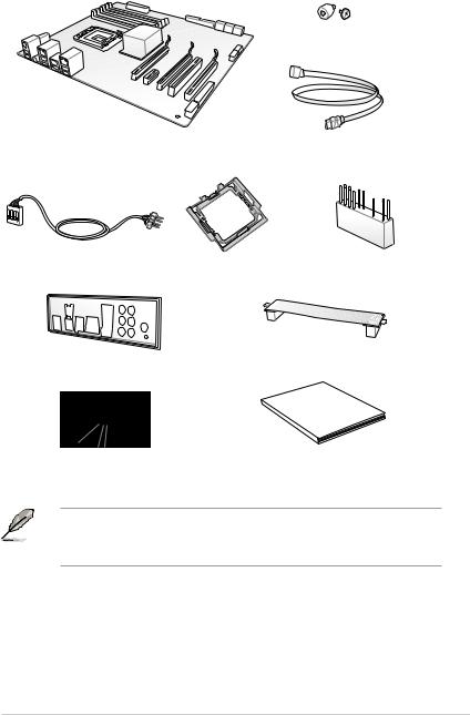
Package contents
Check your motherboard package for the following items
1 x M.2 screws package
ASUS X99-A II motherboard |
4 x Serial ATA 6 Gb/s cables |
1 x RGB LED extension cable |
1 x CPU installation tool |
1 x ASUS Q-Connector |
1 x ASUS Q-Shield |
1 x ASUS SLI™ bridge connector |
|
Manual |
|
User |
1 x Support DVD |
1 x User Manual |
•If any of the above items is damaged or missing, contact your retailer.
•The illustrated items above are for reference only. Actual product specifications may vary with different models.
xv
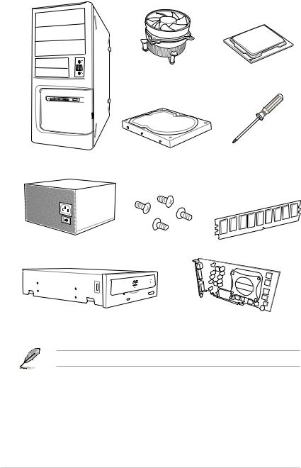
Installation tools and components
Intel® LGA2011-3 compatible CPU Fan |
Intel® LGA2011-3 CPU |
PC chassis |
SATA hard disk drive |
Philips (cross) screwdriver |
Power supply unit |
1 bag of screws |
DIMM |
SATA optical disc drive (optional) |
Graphics card |
The tools and components in the table above are not included in the motherboard package.
xvi
Product Introduction |
1 |
1.1Motherboard overview
1.1.1Before you proceed
Take note of the following precautions before you install motherboard components or change any motherboard settings.
• Unplug the power cord from the wall socket before touching any component.
•Before handling components, use a grounded wrist strap or touch a safely grounded object or a metal object, such as the power supply case, to avoid damaging them due to static electricity.
•Hold components by the edges to avoid touching the ICs on them.
•Whenever you uninstall any component, place it on a grounded antistatic pad or in the bag that came with the component.
•Before you install or remove any component, ensure that the ATX power supply is switched off or the power cord is detached from the power supply. Failure to do so may cause severe damage to the motherboard, peripherals, or components.
<![if ! IE]><![endif]>Chapter 1
ASUS X99-A II |
1-1 |

<![endif]>1 Chapter
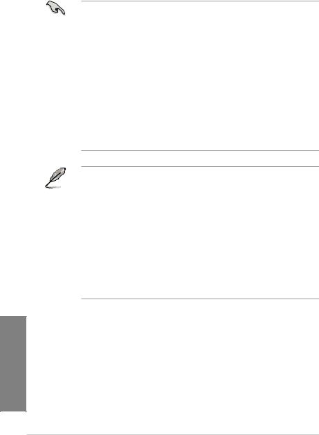
1.1.2Motherboard layout
Refer to 1.1.9 Internal connectors and 2.3.1 Rear I/O connection for more information about rear panel connectors and internal connectors.
1-2 |
Chapter 1: Product Introduction |

Layout contents
Connectors/Jumpers/Buttons and switches/Slots |
Page |
|
1. |
DDR4 DIMM slots |
1-5 |
2. |
CPU, CPU optional, extension, and chassis fan connectors (4-pin |
1-25 |
|
CPU_FAN; 4-pin CPU_OPT; 4-pin W_PUMP; 4-pin H_AMP_FAN; 5-pin |
|
|
EXT_FAN, 4-pin CHA_FAN1-2) |
|
3. |
LGA2011-3 CPU socket |
1-4 |
4. |
ATX power connectors (24-pin EATXPWR; 8-pin EATX12V_1; 4-pin |
1-26 |
|
EZTX12V_2) |
|
5. |
MemOK! button |
1-10 |
6. |
Intel® X99 Serial ATA 6 Gb/s connectors (7-pin SATA6G_12, SATA6G_34, |
1-21 |
|
SATA6G_56/SATAEXPRESS, SATA6G_78, SATA6G_910) |
|
7. |
USB 3.0 connectors (20-1 pin USB3_12, USB3_34) |
1-23 |
8. |
CPU Over Voltage jumper (3-pin CPU_OV) |
1-13 |
9. |
U.2 connector (U.2) |
1-33 |
10. |
EZ XMP switch |
1-11 |
11. |
Thunderbolt header (5-pin TB_HEADER) |
1-29 |
12. |
Clear RTC RAM jumper (2-pin CLRTC) |
1-12 |
13. |
System panel connector (20-8 pin PANEL) |
1-27 |
14. |
DirectKey connector (2-pin DRCT) |
1-28 |
15. |
USB 2.0 connectors (10-1 pin USB1112; USB1314) |
1-24 |
16. |
T_Sensor connector (2-pin T_SENSOR1) |
1-29 |
17. |
M.2 socket 3 |
1-22 |
18. |
TPM connector (14-1 pin TPM) |
1-28 |
19. |
Q-Code LEDs |
1-15 |
20. |
Reset button |
1-9 |
21. |
Power-on button |
1-9 |
22. |
Aura Strip Headers (4-pin RGB_HEADER) |
1-32 |
23. |
Serial port connector (10-1 pin COM) |
1-30 |
24. |
Front panel audio connector (10-1 pin AAFP) |
1-31 |
|
|
|
25. |
Digital audio connector (4-1 pin SPDIF_OUT) |
1-22 |
<![endif]>Chapter 1
ASUS X99-A II |
1-3 |
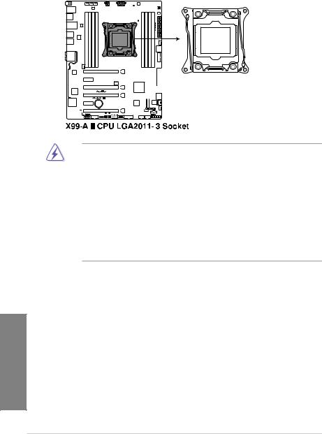
1.1.3Central Processing Unit (CPU)
The motherboard comes with a surface mount LGA2011-3 socket designed for Intel® Core™ i7 processors.
• Ensure that all power cables are unplugged before installing the CPU.
•Upon purchase of the motherboard, ensure that the PnP cap is on the socket and the socket contacts are not bent. Contact your retailer immediately if the PnP cap is missing, or if you see any damage to the PnP cap/socket contacts/motherboard components. ASUS will shoulder the cost of repair only if the damage is shipment/ transit-related.
•Keep the cap after installing the motherboard. ASUS will process Return Merchandise Authorization (RMA) requests only if the motherboard comes with the cap on the LGA2011-3 socket.
•The product warranty does not cover damage to the socket contacts resulting from incorrect CPU installation/removal, or misplacement/loss/incorrect removal of the PnP cap.
<![if ! IE]><![endif]>1 Chapter
1-4 |
Chapter 1: Product Introduction |
1.1.4System memory
The motherboard comes with eight (8) DDR4 (Double Data Rate 4) Quad Inline Memory Modules (DIMM) slots.
A DDR4 module is notched differently from a DDR, DDR2, or DDR3 module. DO NOT install a DDR, DDR2, or DDR3 memory module to the DDR4 slot.
Recommended memory configurations
<![if ! IE]><![endif]>Chapter 1
ASUS X99-A II |
1-5 |
Memory configurations
You may install 2 GB, 4 GB and 8 GB unbuffered and non ECC DDR4 DIMMs into the DIMM sockets.
• You may install varying memory sizes in Channel A, Channel B, Channel C, and Channel D. The system maps the total size of the lower-sized channel for the dualchannel configuration. Any excess memory from the higher-sized channel is then mapped for single-channel operation.
•According to Intel® CPU spec, DIMM voltage below 1.65 V is recommended to protect the CPU.
•Due to the memory address limitation on 32-bit Windows® OS, when you install 4GB or more memory on the motherboard, the actual usable memory for the OS can be about 3GB or less. For effective use of memory, we recommend that you do any of the following:
a)Use a maximum of 3GB system memory if you are using a 32-bit Windows® OS.
b)Install a 64-bit Windows® OS when you want to install 4 GB or more on the motherboard.
c)For more details, refer to the Microsoft® support site at http://support.microsoft. com/kb/929605/en-us.
• The default memory operation frequency is dependent on its Serial Presence Detect (SPD), which is the standard way of accessing information from a memory module. Under the default state, some memory modules for overclocking may operate at a lower frequency than the vendor-marked value. To operate at the vendor-marked or at a higher frequency, refer to section 3.5 Ai Tweaker menu for manual memory frequency adjustment.
•For system stability, use a more efficient memory cooling system to support a full memory load (8 DIMMs) or overclocking condition.
•Always install the DIMMS with the same CAS Latency. For an optimum compatibility, we recommend that you install memory modules of the same version or data code (D/C) from the same vendor. Check with the vendor to get the correct memory modules.
•The design of the DIMM fan may vary. Ensure that the DIMM fan fits to the motherboard.
<![if ! IE]><![endif]>1 Chapter
1-6 |
Chapter 1: Product Introduction |
1.1.5Expansion slots
Unplug the power cord before adding or removing expansion cards. Failure to do so may cause you physical injury and damage motherboard components.
|
|
|
|
|
|
|
|
|
|
|
|
|
|
|
|
|
|
|
|
|
|
|
|
|
|
|
|
|
|
|
|
|
|
|
|
|
|
|
|
|
|
|
|
|
|
|
|
|
|
|
|
|
|
|
|
|
|
|
|
|
|
|
|
|
|
|
|
|
|
|
|
|
|
|
|
|
|
|
|
|
|
|
|
|
|
|
|
|
|
|
|
|
|
|
|
|
|
|
|
|
|
|
|
|
|
|
|
|
|
|
|
|
|
|
|
|
|
|
|
|
|
|
|
|
|
|
|
|
|
|
|
|
|
|
|
|
|
|
|
|
|
|
|
|
|
|
|
|
|
|
|
|
|
|
|
|
|
|
|
|
|
|
|
|
|
|
|
|
|
|
|
|
|
|
|
|
|
|
|
|
|
|
|
|
|
|
|
|
|
|
|
|
|
|
|
|
|
|
|
|
|
|
|
|
|
|
|
|
|
|
|
|
|
|
|
|
|
|
|
|
|
|
|
|
|
|
|
|
|
|
|
|
|
|
|
|
|
|
|
|
|
|
|
|
|
|
|
|
|
|
|
|
|
|
|
|
|
|
|
|
|
|
|
|
|
|
|
|
|
|
|
|
|
|
|
|
|
|
|
|
|
|
|
|
|
|
|
|
|
|
|
|
|
|
|
|
|
|
|
|
|
|
|
|
|
|
|
|
|
|
|
|
|
|
|
|
|
|
|
|
|
|
|
|
|
|
|
|
|
|
|
|
|
|
|
|
|
|
|
|
|
|
|
|
|
|
|
|
|
|
|
|
|
|
|
|
|
|
|
|
|
|
|
|
|
|
|
|
|
|
|
|
|
|
|
|
|
|
|
|
|
|
|
|
|
|
|
|
|
|
|
|
|
|
|
|
|
|
|
|
|
|
|
|
|
|
|
|
|
|
|
|
|
|
|
|
|
|
|
|
|
|
|
|
|
|
|
|
|
|
|
|
|
|
|
|
|
|
|
|
|
|
|
|
|
|
|
|
|
|
|
|
|
|
|
|
|
|
|
|
|
|
|
|
|
|
|
|
|
|
|
|
|
|
|
|
|
|
|
|
|
|
|
|
|
|
|
|
|
|
|
|
|
|
|
|
|
|
|
|
|
|
|
|
|
|
|
|
|
|
|
|
|
|
|
|
|
|
|
|
|
|
|
|
|
|
|
|
|
|
|
|
|
|
|
|
|
|
|
|
|
|
|
|
|
|
|
|
|
|
|
|
|
|
|
|
|
|
|
|
|
|
|
|
|
|
|
|
|
|
|
|
|
|
|
|
|
|
|
|
|
|
|
|
|
|
|
|
|
|
|
|
|
|
|
|
|
|
|
|
|
|
|
|
|
|
|
|
|
|
|
|
|
|
|
|
|
|
|
|
|
|
|
|
|
|
|
|
|
|
|
|
|
|
|
|
|
|
|
|
|
|
|
|
|
|
|
|
|
|
|
|
|
|
|
|
|
|
|
|
|
|
|
|
|
|
|
|
|
|
|
|
|
|
|
|
|
|
|
|
|
|
|
|
|
|
|
|
|
|
|
|
|
|
|
|
|
|
|
|
|
|
|
|
|
|
|
|
|
|
|
|
|
|
|
|
|
|
|
|
|
|
|
|
|
|
|
|
|
|
|
|
|
|
|
|
|
|
|
|
|
|
|
|
|
|
|
|
|
|
|
|
|
|
|
|
|
|
|
|
|
|
|
|
|
|
|
|
|
|
|
|
|
|
|
|
|
|
|
|
|
|
|
|
|
|
|
|
|
|
|
|
|
|
|
|
|
|
|
|
|
|
|
|
|
|
|
|
|
|
|
|
|
|
|
|
|
|
|
|
|
|
|
|
|
|
|
|
|
|
|
|
|
|
|
|
|
|
|
|
|
|
|
|
|
|
|
|
|
|
|
|
|
|
|
|
|
|
|
|
|
|
|
|
|
|
|
|
|
|
|
|
|
|
|
|
|
|
|
|
|
|
|
|
|
|
|
|
|
|
|
|
|
|
|
|
|
|
|
|
|
|
|
|
|
|
|
|
|
|
|
|
|
|
|
|
|
|
|
|
|
|
|
|
|
|
|
|
|
|
|
|
|
|
|
|
|
|
|
|
|
|
|
|
|
|
|
|
|
|
|
|
|
|
|
|
|
|
|
|
|
|
|
|
|
|
|
|
|
|
|
|
|
|
|
|
|
|
|
|
|
|
|
|
|
|
|
|
|
|
|
|
|
|
|
|
|
|
|
|
|
|
|
|
|
|
|
|
|
|
|
|
|
|
|
|
|
|
|
|
|
|
|
|
|
|
|
|
|
|
|
|
|
|
|
|
|
|
|
|
|
|
|
|
|
|
|
|
|
|
|
|
|
|
|
|
|
|
|
|
|
|
|
|
|
|
|
|
|
|
|
|
|
|
|
|
|
|
|
|
|
|
|
|
|
|
|
|
|
|
|
|
|
|
|
|
|
|
|
|
|
|
|
|
|
|
|
|
|
|
|
|
|
|
|
|
|
|
|
|
|
|
|
|
|
|
|
|
|
|
|
|
|
|
|
|
|
|
|
|
|
|
|
|
|
|
|
|
|
|
|
|
|
|
|
|
|
|
|
|
|
|
|
|
|
|
|
|
|
|
|
|
|
|
|
|
|
|
|
|
|
|
|
|
|
|
|
|
|
|
|
|
|
|
|
|
|
|
|
|
|
|
|
|
|
|
|
|
|
|
|
|
|
|
|
|
|
|
|
|
|
|
|
|
|
|
|
|
|
|
|
|
|
|
|
|
|
|
|
|
|
|
|
|
|
|
|
|
|
|
|
|
|
|
|
|
|
|
|
|
|
|
|
|
|
|
|
|
|
|
|
|
|
|
|
|
|
|
|
|
|
|
|
|
|
|
|
|
|
|
|
|
|
|
|
|
|
|
|
|
|
|
|
|
|
|
|
|
|
|
|
|
|
|
|
|
|
|
|
|
|
|
|
|
|
|
|
|
|
|
|
|
|
|
|
|
|
|
|
|
|
|
|
|
|
|
|
|
|
|
|
|
|
|
|
|
|
|
|
|
|
|
|
|
|
|
|
|
|
|
|
|
|
|
|
|
|
|
|
|
|
|
|
|
|
|
|
|
|
|
|
|
|
|
|
|
|
|
|
|
|
|
|
|
|
|
|
|
|
|
|
|
|
|
|
|
|
|
|
|
|
|
|
|
|
|
|
|
|
|
|
|
|
|
|
|
|
|
|
|
|
|
|
|
|
|
|
|
|
|
|
|
|
|
|
|
|
|
|
|
|
|
|
|
|
|
|
|
|
|
|
|
|
|
|
|
|
|
|
|
|
|
|
|
|
|
|
|
|
|
|
|
|
|
|
|
|
|
|
|
|
|
|
|
|
|
|
|
|
|
|
|
|
|
|
|
|
|
|
|
|
|
|
|
|
|
|
|
|
|
|
|
|
|
|
|
|
|
|
|
|
|
|
|
|
|
|
|
|
|
|
|
|
|
|
|
|
|
|
|
|
|
|
|
|
|
|
|
|
|
|
|
|
|
|
|
|
|
|
|
|
|
|
|
|
|
|
|
|
|
|
|
|
|
|
|
|
|
|
|
|
|
|
|
|
|
|
|
|
|
|
|
|
|
|
|
|
|
|
|
|
|
|
|
|
|
|
|
|
|
|
|
|
|
|
|
|
|
|
|
|
|
|
|
|
|
|
|
|
|
|
|
|
|
|
|
|
|
|
|
|
|
|
|
|
|
|
|
|
|
|
|
|
|
|
|
|
|
|
|
|
|
|
|
|
|
|
|
|
|
|
|
|
|
|
|
|
|
|
|
|
|
|
|
|
|
|
|
|
|
|
|
|
|
|
|
|
|
|
|
|
|
|
|
|
|
|
|
|
|
|
|
|
|
|
|
|
|
|
|
|
|
|
|
|
|
|
|
|
|
|
|
|
|
|
|
|
|
|
|
|
|
|
|
|
|
|
|
|
|
|
|
|
|
|
|
|
|
|
|
|
|
|
|
|
|
|
|
|
|
|
|
|
|
|
|
|
|
|
|
|
|
|
|
|
|
|
|
|
|
|
|
|
|
|
|
|
|
|
|
|
|
|
|
|
|
|
|
|
|
|
|
|
|
|
|
|
|
|
|
|
|
|
|
|
|
|
|
|
|
|
|
|
|
|
|
|
|
|
|
|
|
|
|
|
|
|
|
|
|
|
|
|
|
|
|
|
|
|
|
|
|
|
|
|
|
|
|
|
|
|
|
|
|
|
|
|
|
|
|
|
|
|
|
|
|
|
|
|
|
|
|
|
|
|
|
|
|
|
|
|
|
|
|
|
|
|
|
|
|
|
|
|
|
|
|
|
|
|
|
|
|
|
|
|
|
|
|
|
|
|
|
|
|
|
|
|
|
|
|
|
|
|
|
|
|
|
|
|
|
|
|
|
|
|
|
|
|
|
|
|
|
|
|
|
|
|
|
|
|
|
|
|
|
|
|
|
|
|
|
|
|
|
|
|
|
|
|
|
|
|
|
|
|
|
|
|
|
|
|
|
|
|
|
|
|
|
|
|
|
|
|
|
|
|
|
|
|
|
|
|
|
|
|
|
|
|
|
|
Slot No. |
|
|
|
|
|
|
|
|
|
|
|
|
|
|
|
|
|
|
|
|
|
|
|
|
Slot Description |
|
|||||||||||||||||||||||
40-LANE |
|
|
|
|
|
|
|
|
|
28-LANE |
|
||||||||||||||||||||||||||||||||||||||
|
|
|
|
|
|
|
|
|
|
|
|
|
|||||||||||||||||||||||||||||||||||||
1 |
|
|
PCIe 3.0/2.0 x16_1 slot |
|
|
|
|
|
|
|
|
|
PCIe 3.0/2.0 x16_1 slot |
|
|||||||||||||||||||||||||||||||||||
2 |
|
|
PCIe 2.0 x1_1 slot |
|
|
|
|
|
|
|
|
|
PCIe 2.0 x1_1 slot |
|
|||||||||||||||||||||||||||||||||||
3 |
|
|
PCIe 2.0 x16_2 slot |
|
|
|
|
|
|
|
|
|
PCIe 2.0 x16_2 slot |
|
|||||||||||||||||||||||||||||||||||
4 |
|
|
PCIe 3.0/2.0 x16_3 slot |
|
|
|
|
|
|
|
|
|
PCIe 3.0/2.0 x16_3 slot |
|
|||||||||||||||||||||||||||||||||||
5 |
|
|
PCIe 2.0 x1_2 slot |
|
|
|
|
|
|
|
|
|
PCIe 2.0 x1_2 slot |
|
|||||||||||||||||||||||||||||||||||
6 |
|
|
PCIe 3.0/2.0 x16_4 slot |
|
|
|
|
|
|
|
|
|
PCIe 3.0/2.0 x16_4 slot |
|
|||||||||||||||||||||||||||||||||||
<![endif]>Chapter 1
ASUS X99-A II |
1-7 |
40-LANE CPU |
PCI Express 3.0 operating mode |
|||
VGA |
PCIe 3.0/2.0 x16_1 |
PCIe 3.0/2.0 x16_3 |
PCIe 3.0/2.0 x16_4 |
|
configuration |
||||
Single VGA/ |
x16 (single VGA |
N/A |
N/A |
|
PCIe card |
recommended) |
|||
|
|
|||
|
|
|
|
|
Dual VGA/PCIe |
x16 |
x16 |
N/A |
|
cards |
||||
|
|
|
||
|
|
|
|
|
Triple VGA/ |
x8 |
x16 |
x8 |
|
PCIe cards |
||||
|
|
|
||
|
|
|
|
|
28-LANE CPU |
|
PCI Express 3.0 operating mode |
||||
VGA configuration |
|
PCIe 3.0/2.0 x16_1 |
|
PCIe 3.0/2.0 x16_3 |
|
PCIe 3.0/2.0 x16_4 |
Single VGA/PCIe card |
|
x16 (single VGA |
|
N/A |
|
N/A |
|
|
|
||||
|
recommended) |
|
|
|||
|
|
|
|
|
|
|
Dual VGA/PCIe cards |
|
x16 |
|
x8 |
|
N/A |
Triple VGA/PCIe cards |
|
x8 |
|
x8 |
|
x8 |
• We recommend that you provide sufficient power when running CrossFireX™ or SLI™ mode.
•Connect a chassis fan to the motherboard connector labeled CHA_FAN1-2 when using multiple graphics cards for better thermal environment.
<![if ! IE]><![endif]>1 Chapter
1-8 |
Chapter 1: Product Introduction |
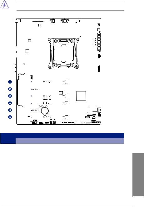
1.1.6Onboard buttons and switches
Onboard buttons and switches allow you to fine-tune performance when working on a bare or open-case system. This is ideal for overclockers and gamers who continually change settings to enhance system performance.
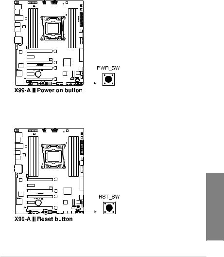
1.Power-on button
The motherboard comes with a power-on button that allows you to power up or wake up the system. The button also lights up when the system is plugged to a power source indicating that you should shut down the system and unplug the power cable before removing or installing any motherboard component.
2.Reset button
Press the reset button to reboot the system.
<![if ! IE]><![endif]>Chapter 1
ASUS X99-A II |
1-9 |

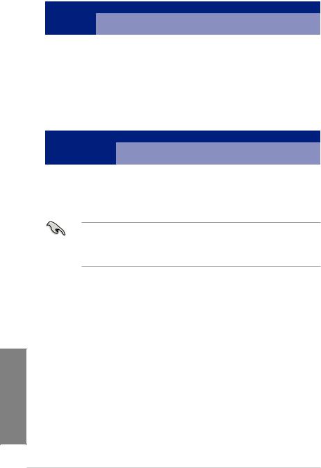
3.MemOK! button
Installing DIMMs that are not compatible with the motherboard may cause system boot failure. If the system fail to boot during POST stage and the DRAM_LED near the MemOK! button lights continuously, press the MemOK! button until the DRAM_LED starts blinking. System will begin automatic memory compatibility tuning and reboot for successful boot.
|
|
|
|
|
|
|
|
|
|
|
|
|
|
|
|
|
|
|
|
|
|
|
|
|
|
|
|
|
|
|
|
|
|
|
|
|
|
|
|
|
|
|
|
|
|
|
|
|
|
|
|
|
|
|
|
|
|
|
|
|
|
|
|
|
|
|
|
|
|
|
|
|
|
|
|
|
|
|
|
|
|
|
|
|
|
|
|
|
|
|
|
|
|
|
|
|
|
|
|
|
|
|
|
|
|
|
|
|
|
|
|
|
|
|
|
|
|
|
|
|
|
|
|
|
|
|
|
|
|
|
|
|
|
|
|
|
|
|
|
|
|
|
|
|
|
|
|
|
|
|
|
|
|
|
|
|
|
|
|
|
|
|
|
|
|
|
|
|
|
|
|
|
|
|
|
|
|
|
|
|
|
|
|
|
|
|
|
|
|
|
|
|
|
|
|
|
|
|
|
|
|
|
|
|
|
|
|
|
|
|
|
|
|
|
|
|
|
|
|
|
|
|
|
|
|
|
|
|
|
|
|
|
|
|
|
|
|
|
|
|
|
|
|
|
|
|
|
|
|
|
|
|
|
|
|
|
|
|
|
|
|
|
|
|
|
|
|
|
|
|
|
|
|
|
|
|
|
|
|
|
|
|
|
|
|
|
|
|
|
|
|
|
|
|
|
|
|
|
|
|
|
|
|
|
|
|
|
|
|
|
|
|
|
|
|
|
|
|
|
|
|
|
|
|
|
|
|
|
|
|
|
|
|
|
|
|
|
|
|
|
|
|
|
|
|
|
|
|
|
|
|
|
|
|
|
|
|
|
|
|
|
|
|
|
|
|
|
|
|
|
|
|
|
|
|
|
|
|
|
|
|
|
|
|
|
|
|
|
|
|
|
|
|
|
|
|
|
|
|
|
|
|
|
|
|
|
|
|
|
|
|
|
|
|
|
|
|
|
|
|
|
|
|
|
|
|
|
|
|
|
|
|
|
|
|
|
|
|
|
|
|
|
|
|
|
|
|
|
|
|
|
|
|
|
|
|
|
|
|
|
|
|
|
|
|
|
|
|
|
|
|
|
|
|
|
|
|
|
|
|
|
|
|
|
|
|
|
|
|
|
|
|
|
|
|
|
|
|
|
|
|
|
|
|
|
|
|
|
|
|
|
|
|
|
|
|
|
|
|
|
|
|
|
|
|
|
|
|
|
|
|
|
|
|
|
|
|
|
|
|
|
|
|
|
|
|
|
|
|
|
|
|
|
|
|
|
|
|
|
|
|
|
|
|
|
|
|
|
|
|
|
|
|
|
|
|
|
|
|
|
|
|
|
|
|
|
|
|
|
|
|
|
|
|
|
|
|
|
|
|
|
|
|
|
|
|
|
|
|
|
|
|
|
|
|
|
|
|
|
|
|
|
|
|
|
|
|
|
|
|
|
|
|
|
|
|
|
|
|
|
|
|
|
|
|
|
|
|
|
|
|
|
|
|
|
|
|
|
|
|
|
|
|
|
|
|
|
|
|
|
|
|
|
|
|
|
|
|
|
|
|
|
|
|
|
|
|
|
|
|
|
|
|
|
|
|
|
|
|
|
|
|
|
|
|
|
|
|
|
|
|
|
|
|
|
|
|
|
|
|
|
|
|
|
|
|
|
|
|
|
|
|
|
|
|
|
|
|
|
|
|
|
|
|
|
|
|
|
|
|
|
|
|
|
|
|
|
|
|
|
|
|
|
|
|
|
|
|
|
|
|
|
|
|
|
|
|
|
|
|
|
|
|
|
|
|
• |
|
|
Refer to section 1.1.8 Onboard LEDs for the exact location of the DIAG_DRAM LED. |
|||||||||||||||||||||||
|
|
|
|
|
|
|
|
|
|
• |
|
|
The DIAG_DRAM LED also lights up when the DIMM is not properly installed. Turn off |
|||||||||||||||||||||||
|
|
|
|
|
|
|
|
|
|
|
|
|
the system and reinstall the DIMM before using the MemOK! function. |
|||||||||||||||||||||||
|
|
|
|
|
|
|
|
|
|
• |
|
|
The MemOK! button does not function under Windows® OS environment. |
|||||||||||||||||||||||
|
|
|
|
|
|
|
|
|
|
• |
|
|
During the tuning process, the system loads and tests failsafe memory settings. It |
|||||||||||||||||||||||
|
|
|
|
|
|
|
|
|
|
|
|
|
takes about 30 seconds for the system to test one set of failsafe settings. If the test |
|||||||||||||||||||||||
|
|
|
|
|
|
|
|
|
|
|
|
|
fails, the system reboots and tests the next set of failsafe settings. The blinking speed |
|||||||||||||||||||||||
|
|
|
|
|
|
|
|
|
|
|
|
|
of the DIAG_DRAM LED increases, indicating different test processes. |
|||||||||||||||||||||||
|
|
|
|
|
|
|
|
|
|
• |
|
|
Due to memory tuning requirement, the system automatically reboots when each |
|||||||||||||||||||||||
|
|
|
|
|
|
|
|
|
|
|
|
|
timing set is tested. If the installed DIMMs still fail to boot after the whole tuning |
|||||||||||||||||||||||
|
|
|
|
|
|
|
|
|
|
|
|
|
process, the DIAG_DRAM LED lights continuously. Replace the DIMMs with ones |
|||||||||||||||||||||||
|
|
|
|
|
|
|
|
|
|
|
|
|
recommended in the Memory QVL (Qualified Vendors Lists) in this user manual or at |
|||||||||||||||||||||||
|
|
|
|
|
|
|
|
|
|
|
|
|
www.asus.com. |
|||||||||||||||||||||||
|
|
|
|
|
|
|
|
|
|
• |
|
|
If you turn off the computer and replace DIMMs during the tuning process, the system |
|||||||||||||||||||||||
|
|
|
|
|
|
|
|
|
|
|
|
|
continues memory tuning after turning on the computer. To stop memory tuning, turn |
|||||||||||||||||||||||
|
|
|
|
|
|
|
|
|
|
|
||||||||||||||||||||||||||
|
|
|
|
|
|
|
|
|
|
|
|
|
off the computer and unplug the power cord for about 5–10 seconds. |
|||||||||||||||||||||||
| <![if ! IE]> <![endif]>1Chapter |
|
|
|
|
|
|
|
|
|
• |
|
|
If your system fails to boot up due to BIOS overclocking, press the MemOK! button |
|||||||||||||||||||||||
|
|
|
|
|
|
|
|
|
|
|
|
to boot and load the BIOS default settings. A message will appear during POST |
||||||||||||||||||||||||
|
|
|
|
|
|
|
|
|
|
|
|
|
||||||||||||||||||||||||
|
|
|
|
|
|
|
|
|
|
|
|
|
reminding you that the BIOS has been restored to its default settings. |
|||||||||||||||||||||||
|
|
|
|
|
|
|
|
|
|
• |
|
|
We recommend that you download and update to the latest BIOS version from |
|||||||||||||||||||||||
|
|
|
|
|
|
|
|
|
|
|
|
|
www.asus.com after using the MemOK! function. |
|||||||||||||||||||||||
|
|
|
|
|
|
|
|
|
|
|
|
|
|
|
|
|
|
|
|
|
|
|
|
|
|
|
|
|
|
|
|
|
|
|
|
|
|
|
|
|
|
|
|
|
|
|
|
|
|
|
|
|
|
|
|
|
|
|
|
|
|
|
|
|
|
|
|
|
|
|
|
|
|
|
|
|
|
|
|
|
|
|
|
|
|
|
|
|
|
|
|
|
|
|
|
|
|
|
|
|
|
|
|
|
|
|
|
|
|
|
1-10 |
Chapter 1: Product Introduction |
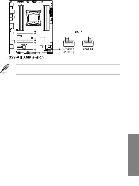
4.EZ XMP switch
Enable this switch to overclock the installed DIMMs, allowing you to enhance the DIMM’s speed and performance.
The EZ XMP LED (XLED1) lights up when you enable the EZ XMP switch. For the location of the EZ XMP LED, refer to section 1.1.8 Onboard LEDs.
<![if ! IE]><![endif]>Chapter 1
ASUS X99-A II |
1-11 |
<![endif]>1 Chapter
1.1.7Jumpers
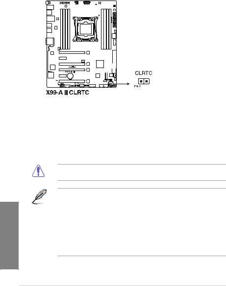
1.Clear RTC RAM jumper (2-pin CLRTC)
This jumper allows you to clear the Real Time Clock (RTC) RAM in CMOS. You can clear the CMOS memory of date, time, and system setup parameters by erasing the CMOS RTC RAM data. The onboard button cell battery powers the RAM data in CMOS, which include system setup information such as system passwords.
To erase the RTC RAM:
1.Turn OFF the computer and unplug the power cord.
2.Short-circuit pin 1-2 with a metal object or jumper cap for about 5-10 seconds.
3.Plug the power cord and turn ON the computer.
4.Hold down the <Delete> key during the boot process and enter BIOS setup to re-enter data.
Except when clearing the RTC RAM, never remove the cap on CLRTC jumper default position. Removing the cap will cause system boot failure!
• If the steps above do not help, remove the onboard battery and move the jumper again to clear the CMOS RTC RAM data. After the CMOS clearance, reinstall the battery.
•You do not need to clear the RTC when the system hangs due to overclocking. For system failure due to overclocking, use the C.P.R. (CPU Parameter Recall) feature. Shut down and reboot the system so the BIOS can automatically reset parameter settings to default values.
•Due to the chipset behavior, AC power off is required to enable C.P.R. function. You must turn off and on the power supply or unplug and plug the power cord before rebooting the system.
1-12 |
Chapter 1: Product Introduction |
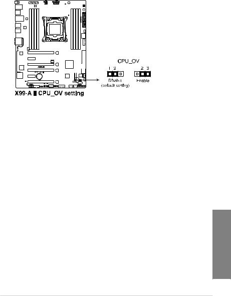
2.CPU Over Voltage jumper (3-pin CPU_OV)
The CPU Over Voltage jumper allows you to set a higher CPU voltage for a flexible overclocking system, depending on the type of the installed CPU. To gain more CPU voltage setting, insert the jumper to pins 2-3. To go back to its default CPU voltage setting, insert the jumper to pins 1-2.
<![if ! IE]><![endif]>Chapter 1
ASUS X99-A II |
1-13 |
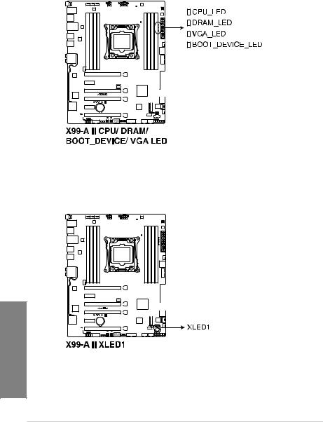
1.1.8Onboard LEDs
1.POST State LEDs
The POST State LEDs provide the status of these key components during POST (Power-On Self-Test): CPU, memory modules, VGA card, and hard disk drives. If an error is found, the critical component’s LED stays lit up until the problem is solved.
2.EZ XMP LED (XLED1)
This LED lights up when you enable the EZ XMP switch.
<![if ! IE]><![endif]>1 Chapter
1-14 |
Chapter 1: Product Introduction |
 Loading...