


Striker
Extreme
Motherboard

E2898
First Edition V1
October 2006
Copyright © 2006 ASUSTeK COMPUTER INC. All Rights Reserved.
No part of this manual, including the products and software described in it, may be reproduced, transmitted, transcribed, stored in a retrieval system, or translated into any language in any form or by any means, except documentation kept by the purchaser for backup purposes, without the express written permission of ASUSTeK COMPUTER INC. (“ASUS”).
Product warranty or service will not be extended if: (1) the product is repaired, modified or altered, unless such repair, modification of alteration is authorized in writing byASUS; or (2) the serial number of the product is defaced or missing.
ASUS PROVIDES THIS MANUAL “AS IS” WITHOUT WARRANTY OF ANY KIND, EITHER EXPRESS OR IMPLIED, INCLUDING BUT NOT LIMITED TO THE IMPLIED WARRANTIES OR CONDITIONS OF MERCHANTABILITY OR FITNESS FOR A PARTICULAR PURPOSE. IN NO EVENT SHALL ASUS, ITS DIRECTORS, OFFICERS, EMPLOYEES OR AGENTS BE LIABLE FOR ANY INDIRECT, SPECIAL, INCIDENTAL, OR CONSEQUENTIAL DAMAGES (INCLUDING DAMAGES FOR LOSS OF PROFITS, LOSS OF BUSINESS, LOSS OF USE OR DATA, INTERRUPTION OF BUSINESS AND THE LIKE), EVEN IF ASUS HAS BEEN ADVISED OF THE POSSIBILITY OF SUCH DAMAGES ARISING FROM ANY DEFECT OR ERROR IN THIS MANUAL OR PRODUCT.
SPECIFICATIONS AND INFORMATION CONTAINED IN THIS MANUAL ARE FURNISHED FOR INFORMATIONAL USE ONLY, AND ARE SUBJECT TO CHANGE AT ANY TIME WITHOUT NOTICE, AND SHOULD NOT BE CONSTRUED AS A COMMITMENT BY ASUS. ASUS ASSUMES NO RESPONSIBILITY OR LIABILITY FOR ANY ERRORS OR INACCURACIES THAT MAY APPEAR IN THIS MANUAL, INCLUDING THE PRODUCTS AND SOFTWARE DESCRIBED IN IT.
Products and corporate names appearing in this manual may or may not be registered trademarks or copyrights of their respective companies, and are used only for identification or explanation and to the owners’ benefit, without intent to infringe.
ii

Contents
Notices........................................................................................................ |
vii |
Safety information..................................................................................... |
viii |
About this guide.......................................................................................... |
ix |
Striker Extreme specifications summary.................................................. |
xi |
Chapter 1: |
Product introduction |
|
|
1.1 |
Welcome!....................................................................................... |
1-1 |
|
1.2 |
Package contents......................................................................... |
1-1 |
|
1.3 |
Special features............................................................................ |
1-2 |
|
|
1.3.1 |
Product highlights............................................................ |
1-2 |
|
1.3.2 |
ASUS AI Lifestyle features ............................................. |
1-4 |
Chapter 2: |
Hardware information |
|
|
2.1 |
Before you proceed...................................................................... |
2-1 |
|
2.2 |
Motherboard overview................................................................. |
2-2 |
|
|
2.2.1 |
Placement direction......................................................... |
2-2 |
|
2.2.2 |
Screw holes..................................................................... |
2-2 |
|
2.2.3 |
ASUS Stack Cool 2......................................................... |
2-3 |
|
2.2.4 |
Motherboard layout.......................................................... |
2-4 |
|
2.2.5 |
Layout contents............................................................... |
2-5 |
2.3 |
Central Processing Unit (CPU).................................................... |
2-7 |
|
|
2.3.1 |
Installing the CPU............................................................ |
2-8 |
|
2.3.2 |
Installing the CPU heatsink and fan.............................. |
2-10 |
|
2.3.3 |
Uninstalling the CPU heatsink and fan.......................... |
2-12 |
|
2.3.4 |
Installing the optional fan............................................... |
2-14 |
2.4 |
System memory.......................................................................... |
2-15 |
|
|
2.4.1 |
Overview........................................................................ |
2-15 |
|
2.4.2 |
Memory configurations.................................................. |
2-16 |
|
2.4.3 |
Installing a DIMM........................................................... |
2-17 |
|
2.4.4 |
Removing a DIMM......................................................... |
2-17 |
2.5 |
Expansion slots.......................................................................... |
2-18 |
|
|
2.5.1 |
Installing an expansion card.......................................... |
2-18 |
|
2.5.2 |
Configuring an expansion card...................................... |
2-18 |
|
2.5.3 |
Interrupt assignments.................................................... |
2-19 |
|
2.5.4 |
PCI slots........................................................................ |
2-20 |
iii

Contents
|
2.5.5 |
PCI Express x1 slot . ...................................................... |
2-20 |
|
2.5.6 |
PCI Express x16 slots ................................................... |
2-20 |
2.6 |
Jumper |
......................................................................................... |
2-21 |
2.7 |
Audio Card ............................................and EL I/O Installation |
2-22 |
|
|
2.7.1 .................................................. |
Audio Card Installation |
2-22 |
|
2.7.2 .......................................................... |
EL I/O Installation |
2-22 |
2.8 |
Connectors.................................................................................. |
2-23 |
|
|
2.8.1 .................................................. |
Rear panel connectors |
2-23 |
|
2.8.2 ........................................................ |
Internal connectors |
2-26 |
|
2.8.3 .......................................................... |
Onboard switches |
2-37 |
Chapter 3: |
Powering up |
|
|
3.1 |
Starting up for the first time........................................................ |
3-1 |
|
3.2 |
Turning off the computer............................................................. |
3-2 |
|
|
3.2.1 |
Using the OS shut down function.................................... |
3-2 |
|
3.2.2 |
Using the dual function power switch.............................. |
3-2 |
Chapter 4: |
BIOS setup |
|
|
4.1 |
Managing and updating your BIOS............................................. |
4-1 |
|
|
4.1.1 |
ASUS Update utility......................................................... |
4-1 |
|
4.1.2 |
Creating a bootable floppy disk....................................... |
4-4 |
|
4.1.3 |
ASUS EZ Flash 2 utility................................................... |
4-5 |
|
4.1.4 |
Updating the BIOS........................................................... |
4-6 |
|
4.1.5 |
Saving the current BIOS file............................................ |
4-8 |
4.2 |
BIOS setup program..................................................................... |
4-9 |
|
|
4.2.1 |
BIOS menu screen........................................................ |
4-10 |
|
4.2.2 |
Menu bar....................................................................... |
4-10 |
|
4.2.3 |
Legend bar..................................................................... |
4-11 |
|
4.2.4 |
Menu items..................................................................... |
4-11 |
|
4.2.5 |
Sub-menu items............................................................. |
4-11 |
|
4.2.6 |
Configuration fields......................................................... |
4-11 |
|
4.2.7 |
Pop-up window.............................................................. |
4-12 |
|
4.2.8 |
General help.................................................................. |
4-12 |
4.3 |
Main menu................................................................................... |
4-13 |
|
|
4.3.1 |
System Time.................................................................. |
4-13 |
iv

Contents
|
4.3.2 |
System Date.................................................................. |
4-13 |
|
4.3.3 |
Language....................................................................... |
4-13 |
|
4.3.4 |
Legacy Diskette A ......................................................... |
4-13 |
|
4.3.5 |
Primary IDE Master/Slave............................................. |
4-14 |
|
4.3.6 |
SATA 1 ~ 6...................................................................................... |
4-16 |
|
4.3.7 |
HDD SMART Monitoring................................................ |
4-17 |
|
4.3.8 |
Installed Memory........................................................... |
4-17 |
|
4.3.9 |
Usable Memory............................................................. |
4-17 |
4.4 |
Extreme Tweaker menu.............................................................. |
4-18 |
|
|
4.4.1 |
AI Tuning....................................................................... |
4-18 |
|
4.4.2 |
Overclocking.................................................................. |
4-21 |
|
4.4.3 |
Over Voltage.................................................................. |
4-23 |
|
4.4.4 |
NVIDIA GPU Ex............................................................. |
4-24 |
|
4.4.5 |
SLI-Ready Memory........................................................ |
4-24 |
|
4.4.6 |
SLI-Ready Memory CPUOC.......................................... |
4-24 |
4.5 |
Advanced menu.......................................................................... |
4-25 |
|
|
4.5.1 |
AI NET2......................................................................... |
4-25 |
|
4.5.2 |
PCIPnP.......................................................................... |
4-26 |
|
4.5.3 |
Onboard Device Configuration...................................... |
4-27 |
4.6 |
Power menu................................................................................ |
4-30 |
|
|
4.6.1 |
ACPI Suspend Type [S1&S3]........................................ |
4-30 |
|
4.6.2 |
ACPI APIC Support [Enabled]....................................... |
4-30 |
|
4.6.3 |
APM Configuration........................................................ |
4-31 |
|
4.6.4 |
Hardware Monitor.......................................................... |
4-33 |
4.7 |
Boot menu................................................................................... |
4-37 |
|
|
4.7.1 |
Boot Device Priority....................................................... |
4-37 |
|
4.7.2 |
Removable Drives......................................................... |
4-38 |
|
4.7.3 |
Hard Disk Drives............................................................ |
4-38 |
|
4.7.4 |
CDROM Drives.............................................................. |
4-38 |
|
4.7.5 |
Boot Settings Configuration .......................................... |
4-39 |

Contents
|
4.7.6 |
Security.......................................................................... |
4-40 |
4.8 |
Tools menu.................................................................................. |
4-42 |
|
|
4.8.1 |
ASUS Music Alarm........................................................ |
4-42 |
|
4.8.2 |
ASUS O.C. Profile......................................................... |
4-43 |
|
4.8.3 ASUS EZ Flash 2.......................................................... |
4-45 |
|
4.9 |
Exit menu..................................................................................... |
4-46 |
|
Chapter 5: |
Software support |
|
|
5.1 |
Installing an operating system.................................................... |
5-1 |
|
5.2 |
Support CD information............................................................... |
5-1 |
|
|
5.2.1 |
Running the support CD.................................................. |
5-1 |
|
5.2.2 |
Drivers menu................................................................... |
5-2 |
|
5.2.3 |
Utilities menu................................................................... |
5-3 |
|
5.2.4 |
Make Disk menu.............................................................. |
5-5 |
|
5.2.5 |
Manuals menu................................................................. |
5-6 |
|
5.2.6 |
ASUS Contact information............................................... |
5-6 |
|
5.2.7 |
Other information............................................................. |
5-7 |
5.3 |
Software information.................................................................... |
5-9 |
|
|
5.3.1 |
ASUS MyLogo3™........................................................... |
5-9 |
|
5.3.2 |
SoundMAX® High DefinitionAudio utility........................ |
5-11 |
|
5.3.3 |
ASUS PC Probe II......................................................... |
5-16 |
|
5.3.4 |
ASUS Music Alarm........................................................ |
5-22 |
|
5.3.5 |
ASUS Ai Booster........................................................... |
5-25 |
5.4 |
RAID configurations................................................................... |
5-26 |
|
|
5.4.1 |
RAID definitions............................................................. |
5-26 |
|
5.4.2 |
NVIDIA® RAID configurations........................................ |
5-27 |
|
5.4.3 |
Silicon Image® RAID configurations .............................. |
5-34 |
5.5 |
Creating a RAID driver disk....................................................... |
5-41 |
|
Chapter 6: |
NVIDIA® SLI™ technology support |
|
|
6.1 |
Overview........................................................................................ |
6-1 |
|
6.2 |
Dual graphics card setup............................................................. |
6-2 |
|
|
6.2.1 |
Installing SLI-ready graphics cards................................. |
6-2 |
|
6.2.2 |
Installing the device drivers............................................. |
6-5 |
|
6.2.3 |
Enabling the multi-GPU feature in Windows®.................. |
6-5 |
vi

Notices
Federal Communications Commission Statement
This device complies with Part 15 of the FCC Rules. Operation is subject to the following two conditions:
•This device may not cause harmful interference, and
•This device must accept any interference received including interference that may cause undesired operation.
This equipment has been tested and found to comply with the limits for a Class B digital device, pursuant to Part 15 of the FCC Rules. These limits are designed to provide reasonable protection against harmful interference in a residential installation. This equipment generates, uses and can radiate radio
frequency energy and, if not installed and used in accordance with manufacturer’s instructions, may cause harmful interference to radio communications. However, there is no guarantee that interference will not occur in a particular installation. If this equipment does cause harmful interference to radio or television reception, which can be determined by turning the equipment off and on, the user is encouraged to try to correct the interference by one or more of the following measures:
•Reorient or relocate the receiving antenna.
•Increase the separation between the equipment and receiver.
•Connect the equipment to an outlet on a circuit different from that to which the receiver is connected.
•Consult the dealer or an experienced radio/TV technician for help.
The use of shielded cables for connection of the monitor to the graphics card is required to assure compliance with FCC regulations. Changes or modifications to this unit not expressly approved by the party responsible for compliance could void the user’s authority to operate this equipment.
Canadian Department of Communications Statement
This digital apparatus does not exceed the Class B limits for radio noise emissions from digital apparatus set out in the Radio Interference Regulations of the Canadian Department of Communications.
This class B digital apparatus complies with Canadian ICES-003.
vii
Safety information
Electrical safety
•To prevent electrical shock hazard, disconnect the power cable from the electrical outlet before relocating the system.
•When adding or removing devices to or from the system, ensure that the power cables for the devices are unplugged before the signal cables are connected. If possible, disconnect all power cables from the existing system before you add a device.
•Before connecting or removing signal cables from the motherboard, ensure that all power cables are unplugged.
•Seek professional assistance before using an adapter or extension cord. These devices could interrupt the grounding circuit.
•Make sure that your power supply is set to the correct voltage in your area. If you are not sure about the voltage of the electrical outlet you are using, contact your local power company.
•If the power supply is broken, do not try to fix it by yourself. Contact a qualified service technician or your retailer.
Operation safety
•Before installing the motherboard and adding devices on it, carefully read all the manuals that came with the package.
•Before using the product, make sure all cables are correctly connected and the power cables are not damaged. If you detect any damage, contact your dealer immediately.
•To avoid short circuits, keep paper clips, screws, and staples away from connectors, slots, sockets and circuitry.
•Avoid dust, humidity, and temperature extremes. Do not place the product in any area where it may become wet.
•Place the product on a stable surface.
•If you encounter technical problems with the product, contact a qualified service technician or your retailer.
This symbol of the crossed out wheeled bin indicates that the product (electrical and electronic equipment) should not be placed in municipal waste. Check local regulations for disposal of electronic products.
viii

About this guide
This user guide contains the information you need when installing and configuring the motherboard.
How this guide is organized
This guide contains the following parts:
•Chapter 1: Product introduction
This chapter describes the features of the motherboard and the new technology it supports.
•Chapter 2: Hardware information
This chapter lists the hardware setup procedures that you have to perform when installing system components. It includes description of the jumpers and connectors on the motherboard.
•Chapter 3: Powering up
This chapter describes the power up sequence and ways of shutting down the system.
•Chapter 4: BIOS setup
This chapter tells how to change system settings through the BIOS Setup menus. Descriptions of the BIOS items are also provided.
•Chapter 5: Software support
This chapter describes the contents of the support CD that comes with the motherboard package.
•Chapter 6: NVIDIA® SLI™ technology support
This chapter tells how to install SLI-ready PCI Express graphics cards.
Where to find more information
Refer to the following sources for additional information and for product and software updates.
1.ASUS websites
The ASUS website provides updated information on ASUS hardware and software products. Refer to the ASUS contact information.
2.Optional documentation
Your product package may include optional documentation, such as warranty flyers, that may have been added by your dealer. These documents are not part of the standard package.
ix

Conventions used in this guide
To make sure that you perform certain tasks properly, take note of the following symbols used throughout this manual.
DANGER/WARNING: Information to prevent injury to yourself when trying to complete a task.
CAUTION: Information to prevent damage to the components when trying to complete a task.
IMPORTANT: Instructions that you MUST follow to complete a task.
NOTE: Tips and additional information to help you complete a task.
Typography
Bold text |
Indicates a menu or an item to select. |
Italics |
Used to emphasize a word or a phrase. |
<Key> |
Keys enclosed in the less-than and greater-than sign |
|
means that you must press the enclosed key. |
|
Example: <Enter> means that you must press the |
|
Enter or Return key. |
<Key1+Key2+Key3> |
If you must press two or more keys simultaneously, the |
|
key names are linked with a plus sign (+). |
|
Example: <Ctrl+Alt+D> |
Command |
Means that you must type the command exactly |
|
as shown, then supply the required item or value |
|
enclosed in brackets. |
|
Example: At the DOS prompt, type the command line: |
|
format A:/S |
Striker Extreme specifications summary
CPU
Chipset
Front Side Bus
Memory
SLI-Ready Memory
Expansion slots
Scalable Link Interface (SLI™)
Storage/RAID
LAN
LGA775 socket for Intel® Core™2 Extreme / Core™2 Duo / Pentium® Extreme / Pentium® D / Pentium® 4 / Celeron® D Processors
Intel® Quad-core CPU Ready
Compatible with Intel® 06/05B/05A processors
Note: Visit the ASUS website at www.asus.com for the Intel® CPU support list.
NVIDIA® nForce 680i SLI
- Supports SLI-Ready Memory Technology
1333** / 1066 / 800 / 533 MHz
Dual-channel memory architecture
- 4 x 240-pin DIMM sockets support non-ECC unbuffered DDR2 800/667/533 MHz memory modules
- Supports up to 8 GB system memory
Note: Visit theASUS website at www.asus.com for the latest Qualified
Vendors List (QVL).
1200 MHz
2 x PCI Express™ x16 slots support NVIDIA® SLI™ technology at full x16, x16 speed (blue)
1 x PCI Express™ 16, at x 8 speed (middle) 1 x PCI Express™ x1
2 x PCI 2.2
Supports two identical NVIDIA® SLI™-Ready graphics cards (both at x16 mode)
Note: The blue PCI Express x 16 slots support NVIDIA® SLI™ technology at full x16, x16 speed. The middle slot is for an add-on card at x8 speed.
Southbridge supports:
- 1 x Ultra DMA 133/100/66/33
- 6 x Serial ATA 3.0 Gb/s
- NVIDIA® MediaShield™ RAID supports RAID 0, 1,
0+1, 5 and JBOD configuration across SerialATA drives
Silicon Image® 3132 SATA controller supports: - 2 x External Serial ATA 3.0 Gb/s ports (SATA-on-the-Go) on the rear panel
NVIDIA® nForce 680i SLI built-in dual Gigabit MAC with external Marvell PHY
- Supports NVIDIA® DualNet®å Technology
(continued on the next page)
xi
Striker Extreme specifications summary
High Definition Audio
IEEE 1394
USB
ASUS Exclusive Overclocking features
ASUS Unique features
Rear panel
SupremeFX Audio Card
- ADI 1988B 8-channel High DefinitionAudio CODEC
- Supports Jack-Sensing, Enumeration,
Multi streaming and Jack-Retasking
- Noise Filter
Coaxial, Optical S/PDIF out
DTS® Connect
ASUS Array Mic
VIA6308P controller supports:
- 2 x IEEE 1394a connectors (1 at mid-board, 1 on the rear panel)
Supports up to 10 USB 2.0/1.1 ports (6 at mid-board, 4 on the rear panel)
Extreme Tweaker
Intelligent overclocking tools:
- AI NOS™ (Non-delay Overclocking System)
- AI Overclocking (intelligent CPU frequency tuner) - AI Booster
Overclocking protection:
- ASUS C.P.R. (CPU Parameter Recall)
LCD Poster
EL I/O
Onboard LED
Onboard Switches: Power / Reset / Clr CMOS
Q-Connector
Q-Fan Plus
ASUS EZ Flash 2
ASUS Music Alarm
ASUS MyLogo 3
1 x LCD Poster
1 x PS/2 Keyboard port (purple)
1 x PS/2 Mouse (green)
1 x Optical S/PDIF Output port
1 x Coaxial S/PDIF Output port
2 x External Serial ATA ports
2 x LAN (RJ45) port
4 x USB 2.0/1.1 ports
1 x IEEE1394a port
1 x Onboard LED switch
(continued on the next page)
xii

Striker Extreme specifications summary
Internal connectors
BIOS features
Manageability
Accessories
Support DVD contents
Form factor
1 x Floppy disk drive connector
1 x IDE connector for 2 devices
6 x Serial ATA connectors
3 x USB 2.0 connectors support six additional USB 2.0 ports
1 x IEEE 1394a port connector
1 x Chassis intrusion connector
1 x 24-pin ATX power connector
1 x 8-pin ATX 12V power connector
1 x S/PDIF output connector
3 x thermal sensor connectors
8 x Fan connectors: 1 x CPU / 1 x Power / 1 x Chassis / 5 x optional fan connectors
1 x EL I/O Shield connector System panel connector
8 Mb AWARD BIOS, PnP, DMI2.0, WfM2.0, SM BIOS 2.3, Multi-Language BIOS
WOL by PME, WOR by PME, Chasis Intrusion, PXE
SLI bridge
ASUS Array Mic
ASUS optional fan
ASUS Q-connector Kit
UltraDMA 133/100/66 cable
Floppy disk drive cable
SATA cables
SATA power cables
Thermal sensor cables
Cable ties
2-port USB2.0 module IEEE1394a module EL I/O Shield
ROG key ring
InterVideo® Media Launcher (OEM version only) User’s manual
The hottest 3D game: Ghost Recon
Device drivers
ASUS PC Probe II
ASUS Update
ASUS AI Booster
Futuremark® 3DMark® 06 Advanced Edition
Kaspersky® Anti-virus
NVIDIA® MediaShield™ RAID
ATX form factor: 12 in x 9.6 in (30.5 cm x 24.5 cm)
*Specifications are subject to change without notice.
** available when the installed CPU is supporting 1333MHz FSB.
xiii

xiv
This chapter describes the motherboard features and the new technologies
it supports.
Product1 introduction

|
Chapter summary |
1 |
|
|
|
||
|
|
|
|
|
|
|
|
1.1 |
Welcome!....................................................................................... |
1-1 |
1.2 |
Package contents......................................................................... |
1-1 |
1.3 |
Special features............................................................................ |
1-2 |
ASUS Striker Extreme

1.1Welcome!
Thank you for buying an ASUS® Striker Extreme motherboard!
The motherboard delivers a host of new features and latest technologies, making it another standout in the long line of ASUS quality motherboards!
Before you start installing the motherboard, and hardware devices on it, check the items in your package with the list below.
1.2Package contents
Check your motherboard package for the following items.
Motherboard |
ASUS Striker Extreme motherboard |
I/O modules |
1 x 1-port IEEE 1394a module |
|
1 x 2-port USB 2.0 module |
Cables |
Serial ATA power and signal cables for 6 devices |
|
1 x Ultra DMA 133/100/66 cable |
|
1 x Floppy disk drive cable |
|
3 x Thermal sensor cables |
|
Cable ties |
Accessories |
I/O shield with EL |
|
1 x ROG key ring |
|
ASUS Array Mic |
|
1 x ASUS Optional Fan |
|
1 x 3-in-1 ASUS Q-Connector Kit |
|
(USB, IEEE 1394, system panel; Retail version only) |
|
1 x ASUS SLI Bridge |
Application DVD |
ASUS motherboard support CD/DVD |
|
InterVideo® Media Launcher (OEM version) |
|
3D Game-Ghost ReconAdvanced Warfighter |
Documentation |
User guide |
If any of the above items is damaged or missing, contact your retailer.
ASUS Striker Extreme |
1- |

1.3Special features
1.3.1Product highlights
Republic of Gamers 
The Republic of Gamers consists only the best of the best. We offer the best hardware engineering, the fastest performance, the most innovating ideas, and we welcome the best gamers to join in.
In the Republic of Gamers, mercy rules are only for the weak, and bragging rights means everything. We believe in making statements and we excel in competitions. If your character matches our trait, then join the elite club, make your presence felt, in the Republic of Gamers.
Green ASUS
This motherboard and its packaging comply with the European Union’s Restriction on the use of Hazardous Substances (RoHS). This is in line with theASUS vision of creating environment-friendly and recyclable products/packaging to safeguard consumers’ health while minimizing the impact on the environment.
Intel® Core™2 / Quad-core Processor Ready
This motherboard supports the latest Intel® Core™2 processor in the LGA775 package. With the new Intel® Core™ microarchitecture technology and 1066 /
800 MHz FSB, the Intel® Core™2 is one of the most powerful and energy efficient
CPUs in the world. This motherboard also supports the latest Intel® Quad-core processor, which is excellent for multi-tasking, multi-media and enthusiastic gamers with 1066 / 800 MHz FSB. See page 2-7 for details.
NVIDIA® nForce® 680i SLI chipset
The NVIDIA® nForce 680i SLI chipset supports the NVIDIA® Scalable Link Interface (SLI™) technology that allows two graphics processing units (GPUs) in a single system. It’s designed for enthusiast, extreme overclocking capability, ultimate gaming performance with SLI technology support. It’s definitely one of the fastest platform in the world. See Chapter 6 for details. The NVIDIA® nForce 680i SLI chipset also supports six (6) Serial ATA 3.0 Gb/s devices, dual PCI Express™ x16 slots at with NVIDIA® SLI™ support at full x16, x16 mode, and up to 10 USB 2.0 ports.
NVIDIA® Scalable Link Interface (SLI™)
NVIDIA SLI™ (Scalable Link Interface) takes advantage of the increased bandwidth of the PCI Express bus architecture and features intelligent hardware and software that allows two GPUs to efficiently work together to deliver earthshattering, scalable performance.
1- |
Chapter 1: Product Introduction |

DDR2 memory support 
The motherboard supports DDR2 memory that features data transfer rates of 800/667/533 MHz to meet the higher bandwidth requirements of the latest
3D graphics, multimedia, and Internet applications. The dual-channel DDR2 architecture doubles the bandwidth of your system memory to boost system performance, eliminating bottlenecks with peak bandwidths of up to 12.8 GB/s. See page 215 for details.
Serial ATA I/II technology and SATA-On-The-Go 


The motherboard fully supports the Serial ATA II 3.0 Gb/s technology through the Serial ATA interfaces and the NVIDIA® nForce® 680i SLI™ chipset. The Serial
ATA3.0 Gb/s specification provides twice the bandwidth of the current SerialATA products with a host of new features, including Native Command Queueing (NCQ), and Power Management (PM) Implementation Algorithm. Serial ATA allows for thinner, more flexible cables with lower pin count and reduced voltage required.
See page 2-27 for details.
Leveraging these Serial ATA 3.0 Gb/s features is the SATA-On-The-Go. Supported by the Silicon Image® 3132 Serial ATA controller are two external Serial ATA 3.0 Gb/s ports on the rear panel that provide smart setup and hot-plug function. See page 2-24 for details.
Dual RAID solution
Onboard RAID controllers provide the motherboard with dual-RAID functionality that allows you to select the best RAID solution for Serial ATA devices.
The NVIDIA® MediaShield™ RAID controller integrated in the NVIDIA® nForce® 680i SLI™ chipset allows RAID 0, RAID 1, RAID 0+1, RAID 5, and JBOD configurations for six SATA3.0 Gb/s connectors. See pages 2-30 and 5-27 for details.
The Silicon Image® 3132 controller supports two additional external Serial ATA 3.0 Gb/s ports on the rear panel and allows RAID 0, RAID 1, and JBOD configurations through port multiplier functions. See page 5-34 for details.
IEEE 1394a support
The IEEE 1394a interface provides high speed digital interface for audio/video appliances such as digital television, digital video camcorders, storage peripherals & other PC portable devices. See pages 2-25 and 2-29 for details.
ASUS Striker Extreme |
1- |

S/PDIF digital sound ready
This motherboard provides convenient connectivity to external home theater audio systems via coaxial and optical S/PDIF-out (SONY/PHILIPS Digital Interface) jacks.It allows to transfer digital audio without converting to analog format and keeps the best signal quality. See pages 2-23, 2-25 and 2-28 for details.
Dual Gigabit LAN solution
The motherboard comes with dual Gigabit LAN controllers to provide the total solution for your networking needs. These network controllers use the PCI Express segment to provide faster data bandwidth for your wired or wireless
Internet, LAN, and file sharing requirements. See page 2-23 for details.
1- |
Chapter 1: Product Introduction |
1.3.2ASUS unique features
8-phase cap-less Power design
The 8-phase EL Capless Power Design demonstrates two hardcore commitments of ROG products: ultimate overclocking capability, and ultimate reliability. The 8- phase power design yields unparalleled superiority in the overclocking arena, while the cap-less design removes any worries of capacitor problems once and for all.
Fanless Design
TheASUS fanless design allows multi-directional heat flow from major thermal sources in the motherboard to lower overall system temperature, resulting in quieter operation and longer system life. ASUS has devoted special efforts to address the thermal issues across the motherboard, and most notably in the following areas: CPU, power, VGA, Northbridge and Southbridge. The heat pipe, heatsink, and strategic board layout were tailor made to dissipate heat in the most efficient manner.
AI NOS™ (Non-Delay Overclocking System)
ASUS Non-delay Overclocking System™ (NOS) is a technology that auto detects the CPU loading and dynamically overclocks the CPU speed only when needed. See page 4-18 for details.
Extreme Tweaker 
This feature allows you to fine tune the CPU/memory voltage and gradually increase the memory Front Side Bus (FSB) and PCI Express frequency at 1MHz increment to achieve maximum system performance.
ASUS Q-Connector 
The ASUS Q-Connector allows you to connect or disconnect chassis front panel cables in one easy step. This unique adapter eliminates the trouble of plugging in one cable at a time, making connection quick and error-free. See pages 2-36 for details.
ASUS Striker Extreme |
1- |

ASUS LCD Poster 
The LCD Poster displays actual boot error messages instead of codes that other debug cards show. This unique feature allows you to easily find out which devices fail during the boot process, eliminating guesswork and allowing you to solve the
problem immediately.
Onboard LEDs
This motherboard features onboard LEDs located near connector labels, allowing you to connect cables and devices without a flashlight. With thisASUS-patented feature, you can easily identify connector locations to make sure that cables and devices are plugged in and installed correctly.
Onboard Switches 
A power-on button, a resetbutton, and a clear CMOS button are onboard to provide overclockers and gamers the convenience of fine-tuning performance when working on a bare (open-case) system. Press the power-on button to wake up the system, the reset button to reboot, and the clear CMOS button to clear setup information when the system hangs due to overclocking. See page 2-37 for details.
ASUS Q-Fan plus technology 
The ASUS Q-Fan plus technology smartly adjusts the CPU and chassis fan
1 speeds according to the system loading to ensure quiet, cool, and efficient operation. See page 4 35 for details.
ASUS Multi-language BIOS
The multi-language BIOS allows you to select the language of your choice from the available options. The localized BIOS menus allow easier and faster configuration.
See page 4-13 for details.
ASUS MyLogo3 
This new feature present in the motherboard allows you to personalize and add style to your system with customizable boot logos. See page 5-9 for details.
1- |
Chapter 1: Product Introduction |

C.P.R. (CPU Parameter Recall)
The C.P.R. feature of the motherboard BIOS allows automatic re-setting to the BIOS default settings in case the system hangs due to overclocking. When the system hangs due to overclocking, C.P.R. eliminates the need to open the system chassis and clear the RTC data. Simply shut down and reboot the system, and the BIOS automatically restores the CPU default setting for each parameter.
ASUS Music Alarm 
Wake up to the music of your choice instead of the irritating sound of an alarm clock. The ASUS Music Alarm gives you a personal wake-up call with your favorite CD music without having to enter the OS. See pages 4-42 and 5-22 for details.
Supreme FX features 
This feature can enhance speech-centric applications like Skype, online game, video conference and recording.
ASUS Array Mic 
The Bundled Superbeam Array Microphone receives only the sound coming from the reception cone and ignores the sounds coming from other directions. This mechanism eliminates a large number of interferences, including neighboring speakers and reverberations. It also uses advanced de-reverberation techniques to reduce echo and minimize its effect on the speech engine. This feature can enchance speech-centric applications like Skype, online game, video conference, and recording. See page 5-15 for details.
Noise Filter 
This feature detects repetitive and stationary noises (non-voice signals) like computer fans, air conditioners, and other background noises then eliminates
it in the incoming audio stream while recording. See page 5-15 for details.
DTS® Connect 
This feature is consists of two elements: DTS interactive and DTS NEO:PC. DTS interactive re-encodes your stereo or multi-channel sound into a DTS audio signal and send it out from your PC to any DTS enabled system. While DTS NEO:PC turns your stereo audio such as MP3, WMA, CD, and other sound format into a convincing multi-channel audio experience. See page 5-14 for details.
ASUS Striker Extreme |
1- |

1- |
Chapter 1: Product Introduction |
This chapter lists the hardware setup procedures that you have to perform when installing system components. It includes description of the jumpers and connectors on the motherboard.
Hardware2 information

|
Chapter summary |
2 |
|
|
|
||
|
|
|
|
|
|
|
|
2.1 |
Before you proceed...................................................................... |
2-1 |
2.2 |
Motherboard overview................................................................. |
2-2 |
2.3 |
Central Processing Unit (CPU).................................................... |
2-7 |
2.4 |
System memory.......................................................................... |
2-15 |
2.5 |
Expansion slots.......................................................................... |
2-18 |
2.6 |
Jumper......................................................................................... |
2-21 |
2.7 |
Audio Card and EL I/O Installation............................................ |
2-22 |
2.8 |
Connectors.................................................................................. |
2-23 |
ASUS Extreme Striker
2.1Before you proceed
Take note of the following precautions before you install motherboard components or change any motherboard settings.
•Use a grounded wrist strap or touch a safely grounded object or to a metal object, such as the power supply case, before handling components to avoid damaging them due to static electricity.
•Hold components by the edges to avoid touching the ICs on them.
•Whenever you uninstall any component, place it on a grounded antistatic pad or in the bag that came with the component.
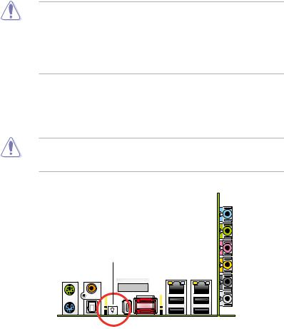
Onboard LED
Blue lights strategically located beside key motherboard connectors allow you to install components conveniently, even without a flashlight.
Before you install or remove any component, make sure to press the onboard
LED switch first and the standby power LED is off. Failure to do so may cause injury or severe damage to the motherboard, peripherals, and/or components.
On Board LED switch |
ASUS Striker Extreme |
2- |
2.2Motherboard overview
Before you install the motherboard, study the configuration of your chassis to ensure that the motherboard fits into it.
Make sure to unplug the power cord before installing or removing the motherboard. Failure to do so can cause you physical injury and damage motherboard components.
2.2.1Placement direction
When installing the motherboard, make sure that you place it into the chassis in the correct orientation. The edge with external ports goes to the rear part of the chassis as indicated in the image below.
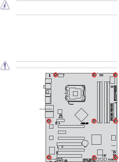
2.2.2Screw holes
Place nine (9) screws into the holes indicated by circles to secure the motherboard to the chassis.
Do not overtighten the screws! Doing so can damage the motherboard.
Place this side towards the rear of the chassis
® |
STRIKER EXTREME |
2- |
Chapter 2: Hardware information |

2.2.3ASUS Stack Cool 2
The motherboard comes with the ASUS Stack Cool 2 cooling solution that lowers the temperature of critical heat generating components. The motherboard uses a special design on the printed circuit board (PCB) to dissipate heat that critical components generate.
ASUS Striker Extreme |
2- |

2.2.4Motherboard layout
|
|
|
24.5cm (9.6in) |
|
|
|
|
|
|
|
P_ELJ1 |
ATX12V |
|
|
|
CPU_FAN |
|
|
Super |
|
|
T: Mouse |
|
|
|
|
|
|
|
|
|
|
PS/2KBMS |
|
|
|
|
|
|
|
|
I/O |
|
B: Keyboard |
|
|
|
|
|
|
|
|
|
|
|
|
|
|
|
|
|
|
|
|
|
SPDIF_O1 |
|
LGA775 |
|
module) |
module) |
|
module) |
module) |
PWR FAN |
|
|
|
|
|
|
||||||
1394a |
|
|
|
|
|
|||||
|
|
|
bit,240-pin |
bit,240-pin |
|
bit,240-pin |
bit,240-pin |
FLOPPY |
|
|
ESATA12 |
|
|
|
|
|
|||||
|
|
|
|
|
|
|
|
|
|
|
|
|
|
|
(64 |
(64 |
|
(64 |
(64 |
EATXPWR |
(12.0in) |
LAN1_USB12 |
|
|
|
DIMMDDR2A1 |
DIMMDDR2A2 |
|
DIMMDDR2B1 |
DIMMDDR2B2 |
||
|
|
|
|
|
|
|
|
|
|
|
|
Silicon Image® |
|
|
|
|
|
|
|
|
|
|
3132 |
|
NVIDIA® |
|
|
|
|
|
|
|
LAN2_USB34 |
CHA_FAN1 |
|
|
|
|
|
|
|
||
NFORCE® 680i SLI |
|
|
|
|
|
|
|
|||
OPT_FAN2 |
USB910 |
|
|
|
|
|
|
IDE |
30.5cm |
|
Audio slot |
|
|
® |
|
|
|
|
|||
|
|
|
|
|
|
|
|
|
|
|
|
OPT_TEMP2 |
|
|
|
|
|
|
|
PRI |
|
88E1116 |
|
PCIEX16_1 |
|
|
|
|
|
|
|
|
|
|
|
|
|
|
|
|
|
||
Marvell |
|
|
|
|
|
|
|
|
|
|
|
PCIEX1 |
|
|
|
|
|
|
|
|
|
Marvell |
|
PCIEX16_2 |
|
NFORCE® 680i SLI |
|
|
|
SATA56 |
|
|
88E1116 |
|
|
|
NVIDIA® |
|
|
|
|
|
|
|
STRIKER EXTREME |
|
|
|
|
|
SATA34 |
|
||
|
|
PCI1 |
CMOS Power |
|
|
|
|
|
|
|
|
|
|
CR2032 3V |
|
|
|
|
|
|
|
|
|
|
Lithium Cell |
|
|
|
|
|
|
|
OPT_TEMP1 |
SB_PWR |
|
|
|
|
|
|
SATA12 |
|
|
|
|
|
|
|
|
|
|
|||
VIA |
OPT_FAN1 |
|
|
BIOS |
CLRTC |
|
|
|||
VT6308P |
PCIEX16_3 |
|
|
|
|
|||||
|
|
|
|
8Mb |
|
|
OPT_FAN4 |
|
||
|
|
PCI2 |
|
CHASSIS |
|
|
|
|||
SPDIF_O2 |
|
|
|
|
OPT_FAN5 |
|
||||
|
|
|
|
|
|
|
|
|||
OPT_TEMP3 |
USB56 |
USB78 |
|
|
|
|
|
|
||
IE1394_2 |
|
|
|
|
|
|
||||
|
ADH |
OPT_FAN3 |
|
|
|
|
|
|
|
|
|
|
|
PWR_SW RST_SW |
CLR_CMOS |
PANEL |
|
||||
|
|
|
|
|
|
|
|
|
|
|
2- |
Chapter 2: Hardware information |
 Loading...