

ASUS P6X58-E PRO User Manual

P6X58-E PRO
Motherboard

ii
E6356
First Edition (V1)
March 2011
Copyright © 2011 ASUSTeK COMPUTER INC. All Rights Reserved.
No part of this manual, including the products and software described in it, may be reproduced,
transmitted, transcribed, stored in a retrieval system, or translated into any language in any form or by any
means, except documentation kept by the purchaser for backup purposes, without the express written
permission of ASUSTeK COMPUTER INC. (“ASUS”).
Product warranty or service will not be extended if: (1) the product is repaired, modied or altered, unless
such repair, modication of alteration is authorized in writing by ASUS; or (2) the serial number of the
product is defaced or missing.
ASUS PROVIDES THIS MANUAL “AS IS” WITHOUT WARRANTY OF ANY KIND, EITHER EXPRESS
OR IMPLIED, INCLUDING BUT NOT LIMITED TO THE IMPLIED WARRANTIES OR CONDITIONS OF
MERCHANTABILITY OR FITNESS FOR A PARTICULAR PURPOSE. IN NO EVENT SHALL ASUS, ITS
DIRECTORS, OFFICERS, EMPLOYEES OR AGENTS BE LIABLE FOR ANY INDIRECT, SPECIAL,
INCIDENTAL, OR CONSEQUENTIAL DAMAGES (INCLUDING DAMAGES FOR LOSS OF PROFITS,
LOSS OF BUSINESS, LOSS OF USE OR DATA, INTERRUPTION OF BUSINESS AND THE LIKE),
EVEN IF ASUS HAS BEEN ADVISED OF THE POSSIBILITY OF SUCH DAMAGES ARISING FROM ANY
DEFECT OR ERROR IN THIS MANUAL OR PRODUCT.
SPECIFICATIONS AND INFORMATION CONTAINED IN THIS MANUAL ARE FURNISHED FOR
INFORMATIONAL USE ONLY, AND ARE SUBJECT TO CHANGE AT ANY TIME WITHOUT NOTICE,
AND SHOULD NOT BE CONSTRUED AS A COMMITMENT BY ASUS. ASUS ASSUMES NO
RESPONSIBILITY OR LIABILITY FOR ANY ERRORS OR INACCURACIES THAT MAY APPEAR IN THIS
MANUAL, INCLUDING THE PRODUCTS AND SOFTWARE DESCRIBED IN IT.
Products and corporate names appearing in this manual may or may not be registered trademarks or
copyrights of their respective companies, and are used only for identication or explanation and to the
owners’ benet, without intent to infringe.
Offer to Provide Source Code of Certain Software
This product may contain copyrighted software that is licensed under the General Public License (“GPL”)
and under the Lesser General Public License Version (“LGPL”). The GPL and LGPL licensed code in this
product is distributed without any warranty. Copies of these licenses are included in this product.
You may obtain the complete corresponding source code (as dened in the GPL) for the GPL Software,
and/or the complete corresponding source code of the LGPL Software (with the complete machinereadable “work that uses the Library”) for a period of three years after our last shipment of the product
including the GPL Software and/or LGPL Software, which will be no earlier than December 1, 2011, either
(1) for free by downloading it from http://support.asus.com/download;
or
(2) for the cost of reproduction and shipment, which is dependent on the preferred carrier and the location
where you want to have it shipped to, by sending a request to:
ASUSTeK Computer Inc.
Legal Compliance Dept.
15 Li Te Rd.,
Beitou, Taipei 112
Taiwan
In your request please provide the name, model number and version, as stated in the About Box of the
product for which you wish to obtain the corresponding source code and your contact details so that we
can coordinate the terms and cost of shipment with you.
The source code will be distributed WITHOUT ANY WARRANTY and licensed under the same license as
the corresponding binary/object code.
This offer is valid to anyone in receipt of this information.
ASUSTeK is eager to duly provide complete source code as required under various Free Open Source
Software licenses. If however you encounter any problems in obtaining the full corresponding source code
we would be much obliged if you give us a notication to the email address gpl@asus.com, stating the
product and describing the problem (please do NOT send large attachments such as source code archives
etc to this email address).

iii
Contents
Notices .....................................................................................................................viii
Safety information ...................................................................................................... ix
About this guide .......................................................................................................... x
P6X58-E PRO specications summary ................................................................... xii
Chapter 1: Product introduction
1.1 Welcome! .................................................................................................... 1-1
1.2 Package contents.......................................................................................1-1
1.3 Special features..........................................................................................1-2
1.3.1 Product highlights........................................................................1-2
1.3.2 Dual Intelligent Processors 2 with DIGI+ VRM ........................... 1-3
1.3.3 ASUS Exclusive Features ........................................................... 1-3
1.3.4 ASUS Quiet Thermal Solutions ...................................................1-4
1.3.5 ASUS EZ DIY ..............................................................................1-4
1.3.6 Other special features ................................................................. 1-5
Chapter 2: Hardware information
2.1 Before you proceed ...................................................................................2-1
2.2 Motherboard overview ............................................................................... 2-2
2.2.1 Motherboard layout ..................................................................... 2-2
2.2.2 Layout contents ...........................................................................2-3
2.2.3 Placement direction.....................................................................2-4
2.2.4 Screw holes.................................................................................2-4
2.3 Central Processing Unit (CPU) .................................................................2-5
2.3.1 Installing the CPU ....................................................................... 2-5
2.3.2 Installing the CPU heatsink and fan ............................................ 2-8
2.3.3 Uninstalling the CPU heatsink and fan........................................2-9
2.4 System memory .......................................................................................2-10
2.4.1 Overview ................................................................................... 2-10
2.4.2 Memory congurations .............................................................. 2-11
2.4.3 Installing a DIMM ...................................................................... 2-17
2.4.4 Removing a DIMM .................................................................... 2-17
2.5 Expansion slots........................................................................................2-18
2.5.1 Installing an expansion card......................................................2-18
2.5.2 Conguring an expansion card ................................................. 2-18
2.5.3 Interrupt assignments................................................................2-19
2.5.4 PCI slots ....................................................................................2-20
2.5.5 PCI Express x1 slot ...................................................................2-20
2.5.6 PCI Express 2.0 x16 slots ......................................................... 2-20

iv
Contents
2.6 Jumpers .................................................................................................... 2-22
2.7 Onboard switches .................................................................................... 2-23
2.8 Onboard LEDs .......................................................................................... 2-26
2.9 Connectors ............................................................................................... 2-27
2.9.1 Rear panel connectors .............................................................. 2-27
2.8.2 Audio I/O connections ............................................................... 2-28
2.9.3 Internal connectors....................................................................2-31
2.9.4 ASUS Q-Connector (system panel) .......................................... 2-39
2.10 Starting up for the rst time .................................................................... 2-40
2.11 Turning off the computer ......................................................................... 2-40
Chapter 3: BIOS setup
3.1 Knowing BIOS ............................................................................................ 3-1
3.2 Updating BIOS ............................................................................................ 3-1
3.2.1 ASUS Update utility.....................................................................3-2
3.2.2 ASUS EZ Flash 2 utility ............................................................... 3-4
3.2.3 ASUS CrashFree BIOS 3 utility...................................................3-5
3.3 BIOS setup program .................................................................................. 3-6
3.3.1 BIOS menu screen ...................................................................... 3-6
3.3.2 Menu bar ..................................................................................... 3-6
3.3.3 Navigation keys ........................................................................... 3-7
3.3.4 Menu items..................................................................................3-7
3.3.5 Submenu items ........................................................................... 3-7
3.3.6 Conguration elds ..................................................................... 3-7
3.3.7 Pop-up window............................................................................3-7
3.3.8 Scroll bar ..................................................................................... 3-7
3.3.9 General help................................................................................3-7
3.4 Main menu ..................................................................................................3-8
3.4.1 SATA 1–6 .................................................................................... 3-8
3.4.2 Storage Conguration ............................................................... 3-10
3.4.3 AHCI Conguration ................................................................... 3-11
3.4.4 System Information ................................................................... 3-11
3.5 Ai Tweaker menu ...................................................................................... 3-12
3.5.1 Ai Overclock Tuner [Auto] .........................................................3-13
3.5.2 CPU Ratio Setting [Auto]...........................................................3-13
3.5.3 Intel(R) SpeedStep(TM) Tech [Enabled] ...................................3-13
3.5.4 Intel(R) TurboMode Tech [Enabled] .......................................... 3-13
3.5.5 Vcore Power Phase [Enabled] .................................................. 3-14

v
Contents
3.5.6 BCLK Frequency [XXX].............................................................3-14
3.5.7 PCIE Frequency [XXX]..............................................................3-14
3.5.8 DRAM Frequency [Auto] ........................................................... 3-14
3.5.9 UCLK Frequency [XXX] ............................................................ 3-14
3.5.10 QPI Link Data Rate [Auto] ......................................................... 3-14
3.5.11 Start auto tuning ........................................................................ 3-14
3.5.12 DRAM Timing Control [Auto] ..................................................... 3-14
3.5.13 CPU Voltage Control [Manual] ..................................................3-16
3.5.14 CPU Voltage [Auto] ..................................................................3-16
3.5.15 CPU PLL Voltage [Auto] ............................................................ 3-17
3.5.16 QPI/DRAM Core Voltage [Auto] ................................................3-17
3.5.17 IOH Voltage [Auto] ....................................................................3-17
3.5.18 IOH PCIE Voltage [Auto] ........................................................... 3-17
3.5.19 ICH Voltage [Auto]..................................................................... 3-17
3.5.20 ICH PCIE Voltage [Auto] ...........................................................3-17
3.5.21 DRAM Bus Voltage [Auto] ......................................................... 3-17
3.5.22 DRAM DATA REF Voltage on CHA/B/C [Auto] .........................3-18
3.5.23 DRAM CTRL REF Voltage on CHA/B/C [Auto] ......................... 3-18
3.5.24 Duty Control [T.Probe] ............................................................... 3-18
3.5.25 Phase Control [Extreme] ........................................................... 3-18
3.5.26 Load-Line Calibration [Auto]......................................................3-18
3.5.27 CPU Current Capability [100%].................................................3-19
3.5.28 VRM Frequency [Auto] .............................................................. 3-19
3.5.29 CPU Differential Amplitude [Auto] .............................................3-19
3.5.30 CPU Clock Skew [Auto] ............................................................ 3-19
3.5.31 CPU Spread Spectrum [Auto] ................................................... 3-19
3.5.32 IOH Clock Skew [Auto]..............................................................3-19
3.5.33 PCIE Spread Spectrum [Auto] .................................................. 3-19
3.6 Advanced menu .......................................................................................3-20
3.6.1 CPU Conguration .................................................................... 3-20
3.6.2 Chipset ...................................................................................... 3-23
3.6.3 Onboard Devices Conguration ................................................ 3-24
3.6.4 USB Conguration .................................................................... 3-26
3.6.5 PCIPnP ..................................................................................... 3-27
3.7 Power menu .............................................................................................. 3-28
3.7.1 Suspend Mode [Auto]................................................................3-28
3.7.2 Repost Video on S3 Resume [No] ............................................ 3-28
3.7.3 ACPI 2.0 Support [Disabled] ..................................................... 3-28

vi
Contents
3.7.4 ACPI APIC Support [Enabled] ................................................... 3-28
3.7.5 APM Conguration .................................................................... 3-29
3.7.6 Hardware Monitor......................................................................3-30
3.7.7 EuP Ready [Disabled] ............................................................... 3-31
3.8 Boot menu ................................................................................................3-32
3.8.1 Boot Device Priority...................................................................3-32
3.8.2 Boot Settings Conguration ...................................................... 3-33
3.8.3 Security ..................................................................................... 3-34
3.9 Tools menu ............................................................................................... 3-36
3.9.1 ASUS EZ Flash 2 ...................................................................... 3-36
3.9.2 ASUS O.C. Prole ..................................................................... 3-37
3.9.3 AI NET 2 .................................................................................... 3-38
3.9.4 Drive Xpert Conguration .......................................................... 3-39
3.10 Exit menu .................................................................................................. 3-40
Chapter 4: Software support
4.1 Installing an operating system .................................................................4-1
4.2 Support DVD information .......................................................................... 4-1
4.2.1 Running the support DVD ........................................................... 4-1
4.2.2 Obtaining the software manuals..................................................4-2
4.3 Software information ................................................................................. 4-3
4.3.1 AI Suite II.....................................................................................4-3
4.3.2 DIGI+ VRM .................................................................................. 4-4
4.3.3 BT GO! ........................................................................................ 4-5
4.3.4 TurboV EVO ................................................................................ 4-6
4.3.5 EPU ............................................................................................. 4-9
4.3.6 FAN Xpert.................................................................................. 4-10
4.3.7 Probe II...................................................................................... 4-11
4.3.8 Audio congurations..................................................................4-12
4.4 RAID congurations ................................................................................4-13
4.4.1 RAID denitions ........................................................................ 4-13
4.4.2 Installing Serial ATA hard disks ................................................. 4-14
4.4.3 Setting the RAID item in BIOS .................................................. 4-14
4.4.4 Intel® Rapid Storage Technology Option ROM utility ................4-15
4.5 Creating a RAID driver disk.....................................................................4-19
4.5.1 Creating a RAID driver disk without entering the OS ................ 4-19
4.5.2 Creating a RAID driver disk in Windows® .................................. 4-19
4.5.3 Installing the RAID driver during Windows® OS installation ...... 4-19
4.5.4 Using a USB oppy disk drive ................................................... 4-20

vii
Contents
Chapter 5: Multiple GPU technology support
5.1 ATI® CrossFireX™ technology .................................................................. 5-1
5.1.1 Requirements .............................................................................. 5-1
5.1.2 Before you begin ......................................................................... 5-1
5.1.3 Installing two CrossFireX™ graphics cards ................................ 5-2
5.1.4 Installing the device drivers ......................................................... 5-3
5.1.5 Enabling the ATI® CrossFireX™ technology ...............................5-3
5.2 NVIDIA® SLI™ technology ......................................................................... 5-4
5.2.1 Requirements .............................................................................. 5-4
5.2.2 Installing two SLI-ready graphics cards ...................................... 5-4
5.2.3 Installing the device drivers ......................................................... 5-5
5.2.4 Enabling the NVIDIA® SLI™ technology ..................................... 5-5
viii
Notices
Federal Communications Commission Statement
This device complies with Part 15 of the FCC Rules. Operation is subject to the following two
conditions:
• This device may not cause harmful interference, and
• This device must accept any interference received including interference that may cause
undesired operation.
This equipment has been tested and found to comply with the limits for a Class B digital
device, pursuant to Part 15 of the FCC Rules. These limits are designed to provide
reasonable protection against harmful interference in a residential installation. This
equipment generates, uses and can radiate radio frequency energy and, if not installed
and used in accordance with manufacturer’s instructions, may cause harmful interference
to radio communications. However, there is no guarantee that interference will not occur
in a particular installation. If this equipment does cause harmful interference to radio or
television reception, which can be determined by turning the equipment off and on, the user
is encouraged to try to correct the interference by one or more of the following measures:
•
Reorient or relocate the receiving antenna.
•
Increase the separation between the equipment and receiver.
•
Connect the equipment to an outlet on a circuit different from that to which the receiver is
connected.
•
Consult the dealer or an experienced radio/TV technician for help.
The use of shielded cables for connection of the monitor to the graphics card is required
to assure compliance with FCC regulations. Changes or modications to this unit not
expressly approved by the party responsible for compliance could void the user’s authority
to operate this equipment.
Canadian Department of Communications Statement
This digital apparatus does not exceed the Class B limits for radio noise emissions from
digital apparatus set out in the Radio Interference Regulations of the Canadian Department
of Communications.
This class B digital apparatus complies with Canadian ICES-003.
REACH
Complying with the REACH (Registration, Evaluation, Authorisation, and Restriction of
Chemicals) regulatory framework, we published the chemical substances in our products at
ASUS REACH website at http://csr.asus.com/english/REACH.htm.
DO NOT throw the motherboard in municipal waste. This product has been designed to
enable proper reuse of parts and recycling. This symbol of the crossed out wheeled bin
indicates that the product (electrical and electronic equipment) should not be placed in
municipal waste. Check local regulations for disposal of electronic products.
DO NOT throw the mercury-containing button cell battery in municipal waste. This symbol
of the crossed out wheeled bin indicates that the battery should not be placed in municipal
waste.

ix
ASUS Recycling/Takeback Services
ASUS recycling and takeback programs come from our commitment to the highest standards
for protecting our environment. We believe in providing solutions for you to be able to
responsibly recycle our products, batteries, other components as well as the packaging
materials. Please go to http://csr.asus.com/english/Takeback.htm for detailed recycling
information in different regions.
Safety information
Electrical safety
• To prevent electrical shock hazard, disconnect the power cable from the electrical outlet
before relocating the system.
• When adding or removing devices to or from the system, ensure that the power cables
for the devices are unplugged before the signal cables are connected. If possible,
disconnect all power cables from the existing system before you add a device.
• Before connecting or removing signal cables from the motherboard, ensure that all
power cables are unplugged.
• Seek professional assistance before using an adapter or extension cord. These devices
could interrupt the grounding circuit.
• Ensure that your power supply is set to the correct voltage in your area. If you are not
sure about the voltage of the electrical outlet you are using, contact your local power
company.
• If the power supply is broken, do not try to x it by yourself. Contact a qualied service
technician or your retailer.
Operation safety
• Before installing the motherboard and adding devices on it, carefully read all the manuals
that came with the package.
• Before using the product, ensure all cables are correctly connected and the power
cables are not damaged. If you detect any damage, contact your dealer immediately.
• To avoid short circuits, keep paper clips, screws, and staples away from connectors,
slots, sockets and circuitry.
• Avoid dust, humidity, and temperature extremes. Do not place the product in any area
where it may become wet.
• Place the product on a stable surface.
• If you encounter technical problems with the product, contact a qualied service
technician or your retailer.

x
About this guide
This user guide contains the information you need when installing and conguring the motherboard.
How this guide is organized
This guide contains the following parts:
• Chapter 1: Product introduction
This chapter describes the features of the motherboard and the new technology it
supports.
• Chapter 2: Hardware information
This chapter lists the hardware setup procedures that you have to perform when
installing system components. It includes description of the switches, jumpers, and
connectors on the motherboard.
• Chapter 3: BIOS setup
This chapter tells how to change system settings through the BIOS Setup menus.
Detailed descriptions of the BIOS parameters are also provided.
• Chapter 4: Software support
This chapter describes the contents of the support DVD that comes with the
motherboard package and the software.
• Chapter 5: Multiple GPU technology support
This chapter describes how to install and congure multiple ATI® CrossFireX™ and
NVIDIA® SLI™ graphics cards.
Where to nd more information
Refer to the following sources for additional information and for product and software updates.
1. ASUS websites
The ASUS website provides updated information on ASUS hardware and software
products. Refer to the ASUS contact information.
2. Optional documentation
Your product package may include optional documentation, such as warranty yers,
that may have been added by your dealer. These documents are not part of the
standard package.

xi
Conventions used in this guide
To ensure that you perform certain tasks properly, take note of the following symbols used
throughout this manual.
DANGER/WARNING: Information to prevent injury to yourself when trying to
complete a task.
CAUTION: Information to prevent damage to the components when trying to
complete a task.
IMPORTANT: Instructions that you MUST follow to complete a task.
NOTE: Tips and additional information to help you complete a task.
Typography
Bold text Indicates a menu or an item to select.
Italic
s Used to emphasize a word or a phrase.
<Key> Keys enclosed in the less-than and greater-than sign means
that you must press the enclosed key.that you must press the enclosed key.
Example: <Enter> means that you must press the Enter or
Return key.Return key.
<Key1> + <Key2> + <Key3> If you must press two or more keys simultaneously, the key
names are linked with a plus sign (+).
Example: <Ctrl> + <Alt> + <Del>
xii
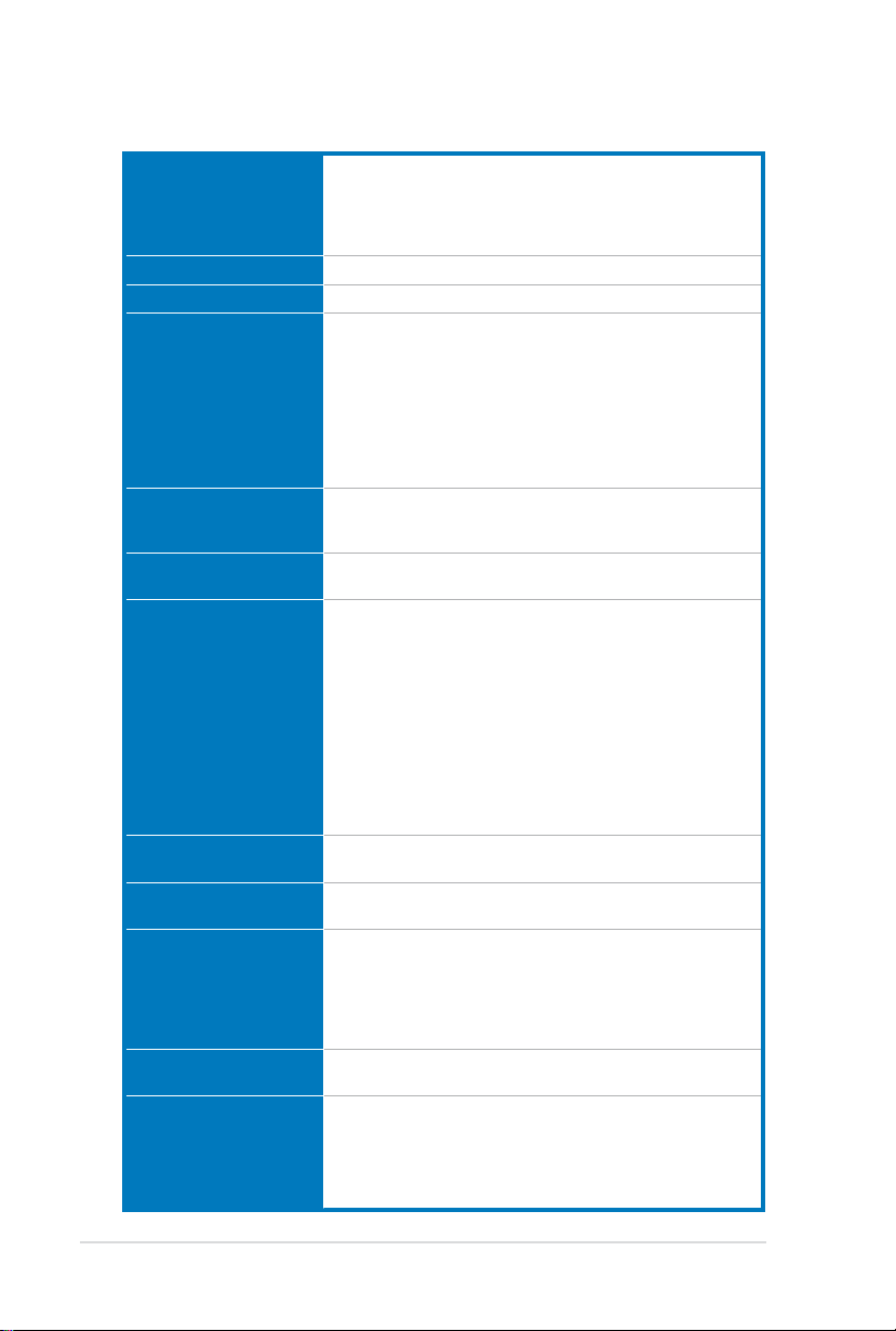
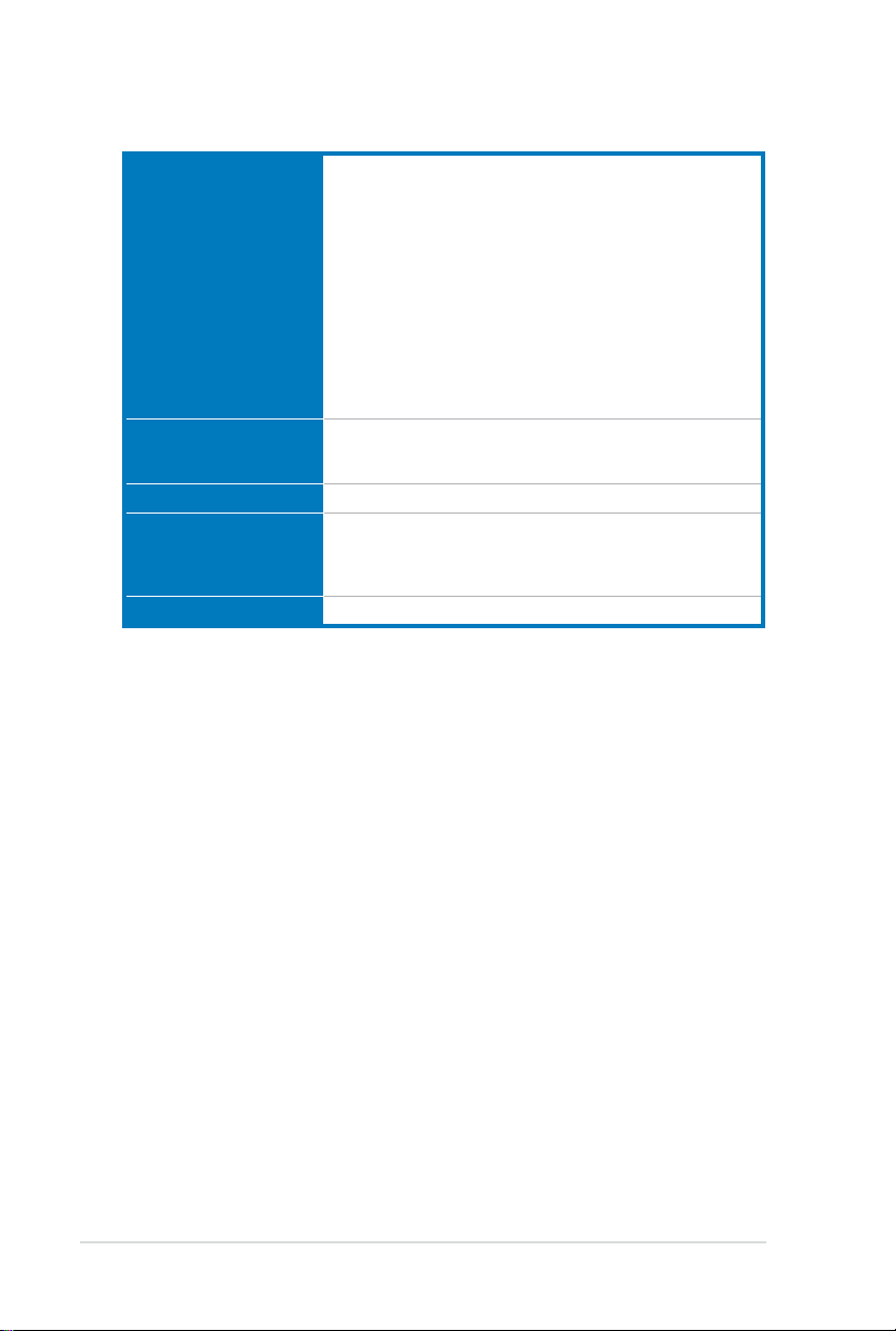
P6X58-E PRO specications summary
CPU Intel® Socket 1366 Core™ i7 Processor Extreme Edition/
Chipset Intel® X58 / ICH10R
System bus Up to 6.4GT/s; Intel® QuickPath Interconnect
Memory 6 x DIMM, max. 48GB*, DDR3 2200(O.C.)**/ 2133(O.C.)/
Expansion slots 3 x PCI Express 2.0 x16 slots (at x16/x8/x8 or x16/x16/x1 mode)
Multi-GPU support Supports NVIDIA® 3-Way SLI™ Technology
Storage Intel® ICH10R Southbridge
LAN Intel® 82567 Gigabit LAN- Dual interconnect between the
Bluetooth Bluetooth v2.1 + EDR
Audio Realtek® ALC889 8-channel High Denition Audio CODEC
IEEE 1394 VIA® 6308P controller supports 2 x IEEE 1394a ports (one at mid-
USB NEC® USB 3.0 controller
Core™ i7 Processors
Supports Intel® 32nm CPU
Supports Intel® Turbo Boost Technology
* Refer to www.asus.com for Intel CPU support list
2000(O.C.)/ 1866(O.C.)/ 1600/ 1333/1066 MHz, non-ECC,
un-buffered memory
Triple channel memory architecture
Supports Intel® Extreme Memory Prole (XMP)
* Refer to www.asus.com or this user manual for the Memory
QVL (Qualied Vendors Lists).
** Hyper DIMM support is subject to the physical characteristics
of individual CPUs.
1 x PCI Express x1 slot
2 x PCI slots
Supports ATI® Quad-GPU CrossFireX™ Technology
- 6 x SATA 3.0 Gb/s ports (blue)
- Intel® Rapid Storage Technology supports SATA RAID 0, 1,
5, and 10
Marvell® PCIe 9128 SATA 6Gb/s controller with Hyper Duo
function
- 2 x SATA 6.0 Gb/s ports (navy blue)
JMicron® JMB362 SATA controller*
- 2 x eSATA 3.0 Gb/s ports
*These SATA ports are for data hard drives only. ATAPI devices
are not supported.
Integrated LAN controller and Physical Layer (PHY)Integrated LAN controller and Physical Layer (PHY)
ASUS BT GO! Utility
- DTS Surround Sensation UltraPC
- BD audio layer Content Protection
- Supports Jack-Detection, Multi-streaming, and Front
Panel Jack-Retasking
- Optical S/PDIF out ports at back I/O
board; one at back panel)board; one at back panel)
- 2 x USB 3.0 ports (at back panel)
Intel® ICH10R Southbridge
- 10 x USB 2.0/1.1 ports
(4 ports at midboard; 6 ports at back panel)
(continued on the next page)

xiii
P6X58-E PRO specications summary
ASUS unique features ASUS Dual Intelligent Processors II:
ASUS Q-Design ASUS Q-LED (DRAM LED)
Back panel I/O ports 1 x PS/2 Keyboard/Mouse combo port
ASUS Digital Power Design
- Industry leading Digital 8+2 Phase Power Design
- ASUS DIGI+ VRM Utility
ASUS TPU
- Auto Tuning, TurboV, TPU switch
ASUS EPU
- EPU
ASUS BT GO!
- Folder Sync, BT Transfer, Shot & Send, BT to Net, Music
Player, Personal Manager
ASUS BT Turbo Remote
- Exclusive Smartphone Interface supporting iPhone,
Android, Windows Mobile, and Symbian systems
ASUS Exclusive Features
- MemOK!
- AI Suite II
- AI Charger
ASUS Quiet Thermal Solution
- ASUS Fanless Design: Heat-pipe solution
- ASUS Fan Xpert
ASUS EZ DIY
- ASUS Q-Shield
- ASUS Q-Connector
- ASUS CrashFree BIOS 3
- ASUS EZ Flash 2
- ASUS MyLogo 2
- Multi-language BIOS
- ASUS C.P.R.(CPU Parameter Recall)
ASUS Q-Slot
1 x Optical S/PDIF Output port
1 x Bluetooth module
2 x eSATA ports
1 x IEEE1394a
1 x RJ45 ports
2 x USB 3.0/2.0 ports (blue)
6 x USB 2.0/1.1 ports
8-channel Audio I/O ports
(continued on the next page)
P6X58-E PRO specications summary
Internal I/O connectors 2 x USB 2.0/1/1 connectors support additional 4 USB ports
BIOS features 16 Mb Flash ROM, AMI BIOS, PnP, DMI 2.0, WfM 2.0,
Manageability WfM 2.0, DMI 2.0, WOL by PME, WOR by PME, PXE
Support DVD contents Drivers
Form factor ATX Form Factor, 12”x 9.6” (30.5cm x 24.4cm)
2 x SATA 6.0Gb/s connectors (navy blue)
6 x SATA 3.0Gb/s connectors (blue)
2 x CPU Fan connectors (2 x 4-pin)
3 x Chassis Fan connectors (3 x 4-pin)
1 x Power Fan connectors (3-pin)
1 x IEEE1394a connector
1 x Front panel audio connector
1 x S/PDIF Out Header
1 x 24-pin EATX Power connector
1 x 8-pin EATX 12V Power connector
1 x System Panel (Q-Connector)
1 x MemOK! Button
1 x TPU switch
SM BIOS 2.3, ACPI 2.0a, Multi-language BIOS,
ASUS EZ Flash 2, ASUS CrashFree BIOS 3
ASUS Utilities
ASUS Update
Anti-virus software (OEM version)
*Specications are subject to change without notice.
xiv
Chapter 1
User Manual
Chapter 1: Product introduction
1.1 Welcome!
Thank you for buying an ASUS® P6X58-E PRO motherboard!
The motherboard delivers a host of new features and latest technologies, making it another
standout in the long line of ASUS quality motherboards!
Before you start installing the motherboard, and hardware devices on it, check the items in
your package with the list below.
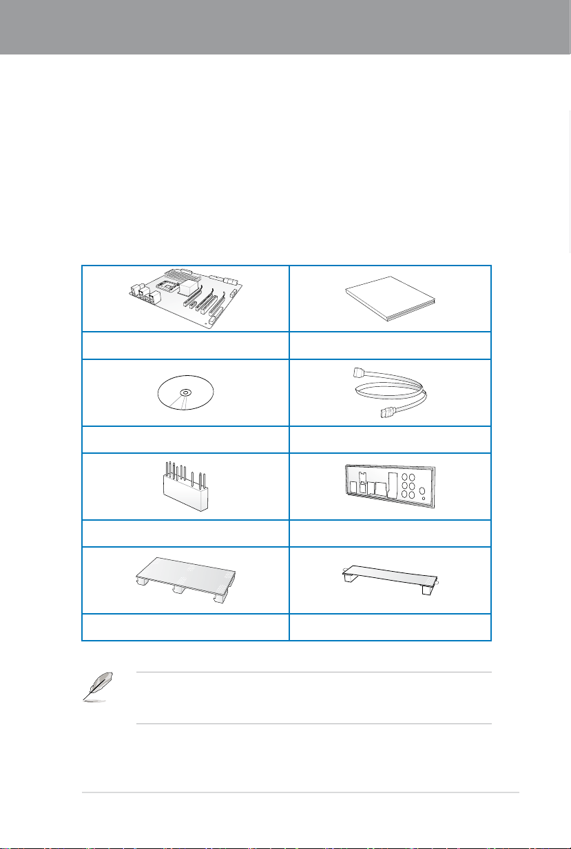
1.2 Package contents
Check your motherboard package for the following items.
1 x ASUS P6X58-E PRO motherboard 1 x User guide
1 x Support DVD
1 x 2-in-1 ASUS Q-Connector kit 1 x Q-shield
2 x Serial ATA 6Gb/s cables
2 x Serial ATA 3Gb/s cables
Chapter 1
1 x 3-way SLI Bridge 1 x SLI Bridge
• If any of the above items is damaged or missing, contact your retailer.
• The illustrated items above are for reference only. Actual product specications may
vary with different models.
ASUS P6X58-E PRO 1-1

1-2 Chapter 1: Product Introduction
Chapter 1
1.3 Special features
1.3.1 Product highlights
Intel® Core™ i7 Processor Extreme Edition / Core™ i7 Processor support
This motherboard supports the latest Intel® Core™ i7 processors in LGA1366 package with
integrated memory controller to support 3-channel (6 DIMMs) DDR3 memory. Supports Intel®
QuickPath Interconnect (QPI) with a system bus of up to 6.4 GT/s and a max bandwidth of
up to 25.6 GB/s. Intel® Core™ i7 processor is one of the most powerful and energy efcient
CPUs in the world.
Intel® X58 Chipset
The Intel® X58 Express Chipset is one of the most powerful chipset designed to support
the Intel® Core™ i7 Processors with LGA1366 package and Intel® next generation system
interconnect interface, Intel® QuickPath Interconnect (QPI), providing improved performance
by utilizing serial point-to-point links, allowing increased bandwidth and stability. It also
supports up to 36 PCI Express 2.0 lanes providing better graphics performance.
Triple-Channel DDR3 2200(O.C.)/ 2133(O.C.)/ 2000(O.C.)/ 1866(O.C.)/ 1600/
1333/ 1066 support
The motherboard supports DDR3 memory that features data transfer rates of
2200(O.C.)/ 2133(O.C.)/ 2000(O.C.)/ 1866(O.C.)/ 1600/ 1333/ 1066MHz to meet the higher
bandwidth requirements of the latest 3D graphics, multimedia, and Internet applications. The
triple-channel DDR3 architecture enlarges the bandwidth of your system memory to boost
system performance.
PCIe 2.0
This motherboard supports the latest PCIe 2.0 devices for double speed and bandwidth
which enhances system performance.
3-Way SLI™ and Quad-GPU CrossFireX™ support
The P6X58-E PRO breaks the boundaries to bring you the multi-GPU choice of either SLI™
or CrossFireX™. The motherboard features a dedicated graphics engine on the most powerful
Intel® X58 platform to optimize PCIe allocation in multiple GPU congurations. Expect a brandnew gaming style you’ve never experienced before! Refer to chapter 5 for details.
True USB 3.0 Support
Experience ultra-fast data transfers at 5.0 Gb/s with USB 3.0–the latest connectivity standard.
Built to connect easily with next-generation components and peripherals, USB 3.0 transfers
data 10X faster and is also backward compatible with USB 2.0 components.
True Serial ATA 6Gb/s support
Supporting the next-generation Serial ATA (SATA) storage interface, this motherboard
delivers up to 6Gb/s data transfer rates. Additionally, get enhanced scalability, faster data
retrieval, double the bandwidth of current bus systems.

ASUS P6X58-E PRO 1-3
Chapter 1
1.3.2 Dual Intelligent Processors 2 with DIGI+ VRM
The world’s rst Dual Intelligent Processors from ASUS pioneered the use of two onboard
chips—EPU (Energy Processing Unit) and TPU (TurboV Processing Unit). New generation
Dual Intelligent Processors 2 with DIGI+ VRM digital power design launch control into a new
era, empowering users with superior exibility and perfect precision to ensure optimized
performance and greater power efciency
DIGI+ VRM
The new ASUS DIGI+ VRM design upgrades motherboard power delivery to a digital
standard. The 8+2 digital architecture delivers precision power, intelligently adjusting PWM
voltage and frequency modulation with minimal power loss. Users can increase overclocking
range and maximize performance through BIOS tuning and exclusive user interface features.
Super Alloy Power chokes contain a metal compound instead of standard iron, supporting
of up to a massive 40A of rated current, or 25% higher than conventional chokes. Unibodyconstructed chokes also eliminate vibration noise, delivering improved performance and
durability even under extreme conditions. DIGI+ VRM digital power design with Super Alloy
Power enables users through superior exibility and perfect precision to ensure optimized
performance and greater power efciency.
TPU
Unleash your performance with ASUS' simple onboard switch or AI Suite II utility. The TPU
chip offers precise voltage control and advanced monitoring through Auto Tuning and TurboV
functions. Auto Tuning offers a user friendly way to automatically optimize the system for fast,
yet stable clock speeds, while TurboV enables unlimited freedom to adjust CPU frequencies
and ratios for optimized performance in diverse situations.
EPU
Tap into the world's rst real-time PC power saving chip through a user-friendly interface.
Get total system-wide energy optimization by automatically detecting current PC loadings
and intelligently moderating power consumption. This also reduces fan noise and extends
component longevity!
1.3.3 ASUS Exclusive Features
BT GO! (Bluetooth)
Onboard Bluetooth wireless design enables smart connectivity to Bluetooth devices with
no additional adapter. ASUS BT GO! comes with 7 special functions that offer signicant
breakthrough in Bluetooth evolution, including Folder Sync, BT Transfer, BT Turbo Remote,
BT-to-Net, Music Player, Shot and Send, and Personal Manager. All are accessible through
the exclusive, user-friendly ASUS interface.
MemOK!
Memory compatibility is among the top concerns during computer upgrades. Worry no more.
MemOK! is the fastest memory booting solution today. This remarkable memory rescue tool
requires nothing but a push of a buttton to patch memory issues and get your system up and
running in no time. The technology is able to determine failsafe settings that can dramatically
improve your system booting success.

1-4 Chapter 1: Product Introduction
Chapter 1
AI Suite II
With its user-friendly interface, ASUS AI Suite II consolidates all the exclusive ASUS features
into one simple to use software package. It allows users to supervise overclocking, energy
management, fan speed control, voltage and sensor readings, and even interact with mobile
devices via Bluetooth. This all-in-one software offers diverse and ease to use functions, with
no need to switch back and forth between different utilities.
1.3.4 ASUS Quiet Thermal Solutions
Fanless Design—Heat-pipe solution
The Heat Pipe design effectively directs the heat generated by the chipsets to the heatsink
near the back IO ports, where it can be carried away by existing airow from CPU fan. The
purpose of the innovative heat pipe design on this motherboard is that the groundbreaking
fanless design does not have lifetime problems as a chipset fan does. Furthermore, it
provides options for users to install side-ow fan or passive cooler. The Heat Pipe design is
the most reliable fanless thermal solution to date.
Fan Xpert
ASUS Fan Xpert intelligently allows you to adjust both the CPU and chassis fan speeds
according to different ambient temperatures caused by different climate conditions in different
geographic regions and your PC’s loading. The built-in variety of useful proles offer exible
controls of fan speed to achieve a quiet and cool environment.
1.3.5 ASUS EZ DIY
ASUS Onboard Switch
With an easy press during overclocking, the exclusive onboard switches allow gamers to
effortless ne-tune the performance without having to short the pins! Refer to page 2-23 for
details.
DO NOT uninstall the heat-pipe by yourself. Doing so may bend the tubing and affect the
heat dissipation performance.
ASUS Q-Design
ASUS Q-Design enhances your DIY experience. All of Q-LED and Q-Slot design speed up
and simplify the DIY process!
ASUS Q-Connector
ASUS Q-Connector allows you to easily connect or disconnect the chassis front panel cables
to the motherboard. This unique module eliminates the trouble of connecting the system
panel cables one at a time and avoiding wrong cable connections.
ASUS EZ Flash 2
ASUS EZ Flash 2 is a user-friendly utility that allows you to update the BIOS without using a
bootable oppy disk or an OS-based utility.

ASUS P6X58-E PRO 1-5
Chapter 1
ASUS O.C. Prole
The motherboard features the ASUS O.C. Prole that allows you to conveniently store or
load multiple BIOS settings. The BIOS settings can be stored in the CMOS or a separate le,
giving you the freedom to share and distribute your favorite settings.
1.3.6 Other special features
DTS Surround Sensation Ultra PC
DTS Surround Sensation UltraPC delivers exceptional 5.1 surround experience through the
most common PC audio setups - your existing stereo speakers or headphones. In addition
to virtual surround, “Bass enhancement” provides stronger low frequency bass sound, and
“Voice clarication” provides clear human dialogue even with loud background sound. With
these technologies, you may experience a better home-theater audio with ease.
ErP Ready
The motherboard is European Union’s Energy-related Products (ErP) ready, and ErP requires
products to meet certain energy efciency requirements in regards to energy consumptions.
This is in line with ASUS vision of creating environment-friendly and energy-efcient products
through product design and innovation to reduce carbon footprint of the product and thus
mitigate environmental impacts.

Chapter 1
1-6 Chapter 1: Product Introduction

Chapter 2
Chapter 2: Hardware information
2.1 Before you proceed
Take note of the following precautions before you install motherboard components or change
any motherboard settings.
• Unplug the power cord from the wall socket before touching any component.
• Before handling components, use a grounded wrist strap or touch a safely grounded
object or a metal object, such as the power supply case, to avoid damaging them due
to static electricity.
• Hold components by the edges to avoid touching the ICs on them.
• Whenever you uninstall any component, place it on a grounded antistatic pad or in the
bag that came with the component.
• Before you install or remove any component, ensure that the ATX power supply is
switched off or the power cord is detached from the power supply. Failure to do so
may cause severe damage to the motherboard, peripherals, or components.
Chapter 2
ASUS P6X58-E PRO 2-1
2-2 Chapter 2: Hardware information
Chapter 2
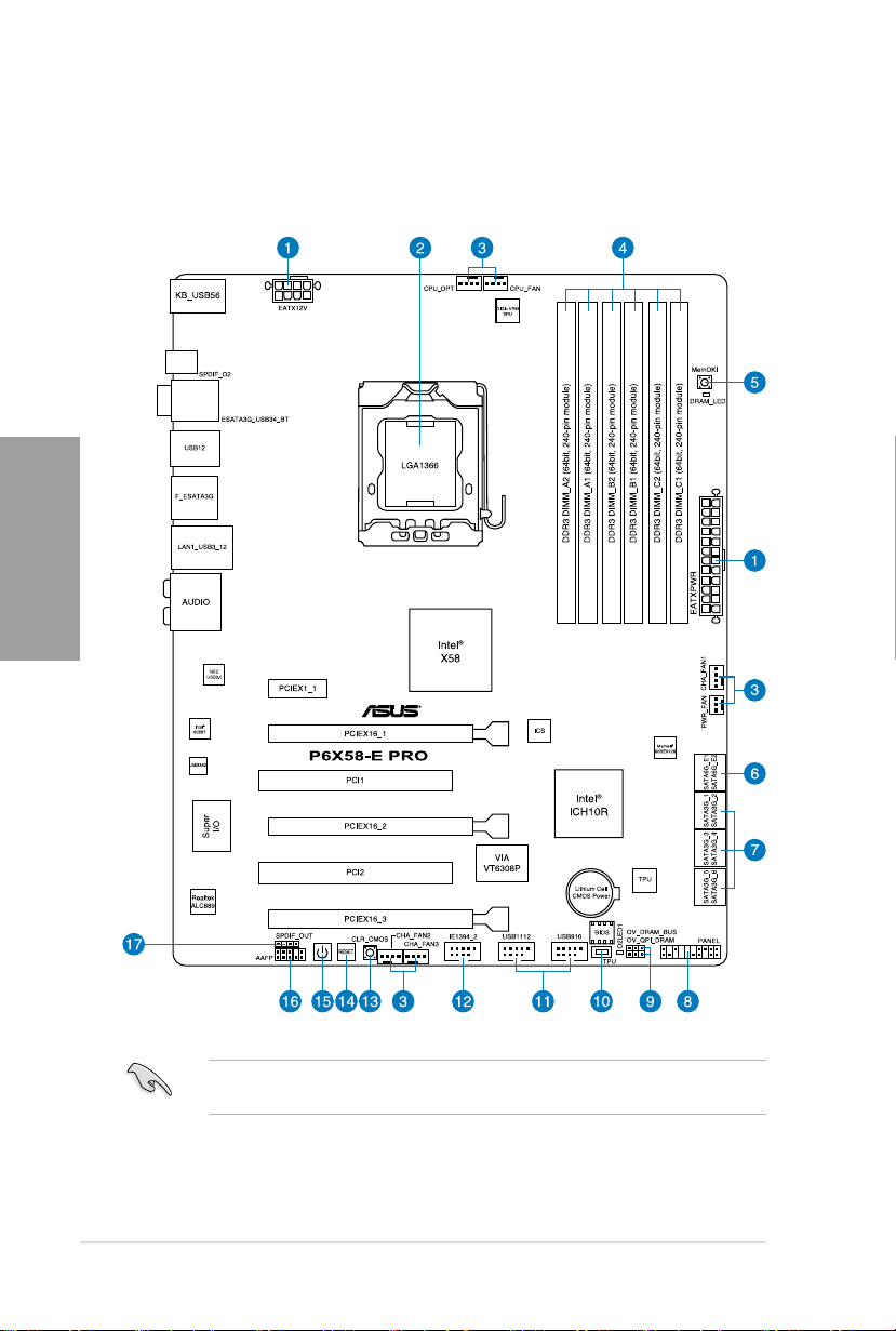
2.2 Motherboard overview
2.2.1 Motherboard layout
Refer to
2.9 Connectors
connectors.
for more information about rear panel connectors and internal

ASUS P6X58-E PRO 2-3
Chapter 2
2.2.2 Layout contents
Connectors/Jumpers/Slots Page
1. ATX power connectors (24-pin EATXPWR, 8-pin EATX12V) 2-37
2. LGA1366 CPU Socket 2-5
3. CPU, chassis, and power fan connectors (4-pin CPU_FAN, 4-pin CPU_OPT,
4-pin CHA_FAN1–3, 3-pin PWR_FAN)
4. DDR3 DIMM slots 2-10
5. MemOK! switch 2-25
6. Marvell® Serial ATA 6.0 Gb/s connectors
(7-pin SATA_6G_E1, 7-pin SATA_6G_E2 [navy blue])
7. ICH10R Serial ATA 3.0 Gb/s connectors (7-pin SATA1–6 [blue]) 2-31
8. System panel connector (20-8 pin PANEL)
9. DRAM Bus / QPI DRAM overvoltage settings ( 3-pin OV_DRAM_BUS;
3-pin OV_QPI_DRAM)
10. TPU switch 2-24
11. USB connectors (10-1 pin USB910, USB1112) 2-33
12. IEEE 1394a port connector (10-1 pin IE1394_2) 2-34
13. Clear RTC RAM switch 2-24
14. Rest switch 2-23
15. Power-on switch 2-23
16. Front panel audio connector (10-1 pin AAFP) 2-36
17. Digital audio connector (4-1 pin SPDIF_OUT) 2-36
2-35
2-32
2-38
2-22
2-4 Chapter 2: Hardware information
Chapter 2
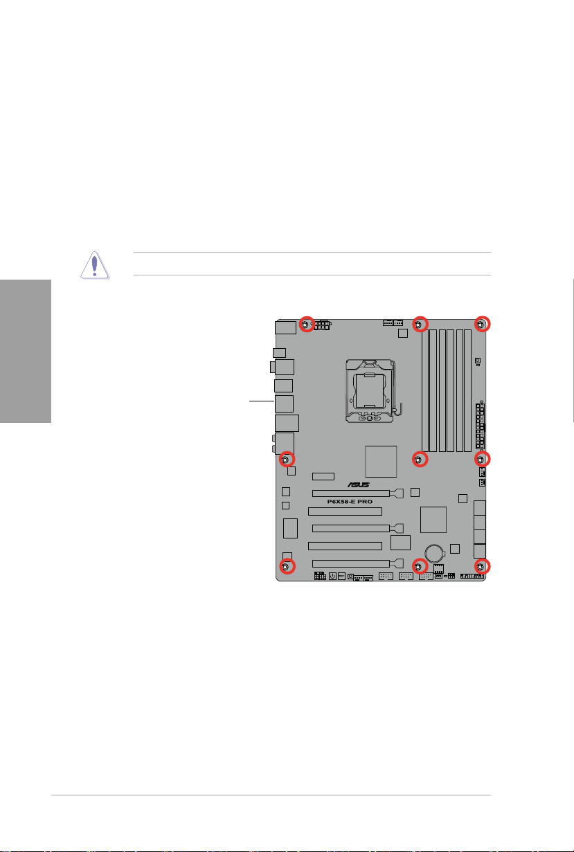
2.2.3 Placement direction
When installing the motherboard, ensure that you place it into the chassis in the correct
orientation. The edge with external ports goes to the rear part of the chassis as indicated in
the image below.
2.2.4 Screw holes
Place nine screws into the holes indicated by circles to secure the motherboard to the
chassis.
DO NOT overtighten the screws! Doing so can damage the motherboard.
Place this side towards
the rear of the chassis
ASUS P6X58-E PRO 2-5
Chapter 2
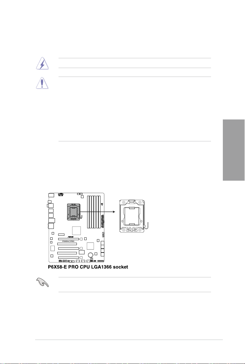
2.3 Central Processing Unit (CPU)
The motherboard comes with a surface mount LGA1366 socket designed for the Intel®
Core™ i7 Processor Extreme Edition / Core™ i7 Processor.
Ensure that all power cables are unplugged before installing the CPU.
• Upon purchase of the motherboard, ensure that the PnP cap is on the socket and
the socket contacts are not bent. Contact your retailer immediately if the PnP cap
is missing, or if you see any damage to the PnP cap/socket contacts/motherboard
components. ASUS will shoulder the cost of repair only if the damage is shipment/
transit-related.
• Keep the cap after installing the motherboard. ASUS will process Return Merchandise
Authorization (RMA) requests only if the motherboard comes with the cap on the
LGA1366 socket.
• The product warranty does not cover damage to the socket contacts resulting from
incorrect CPU installation/removal, or misplacement/loss/incorrect removal of the PnP
cap.
2.3.1 Installing the CPU
To install a CPU:
1. Locate the CPU socket on the motherboard.
Before installing the CPU, ensure that the cam box is facing towards you and the load lever
is on your left.
2-6 Chapter 2: Hardware information
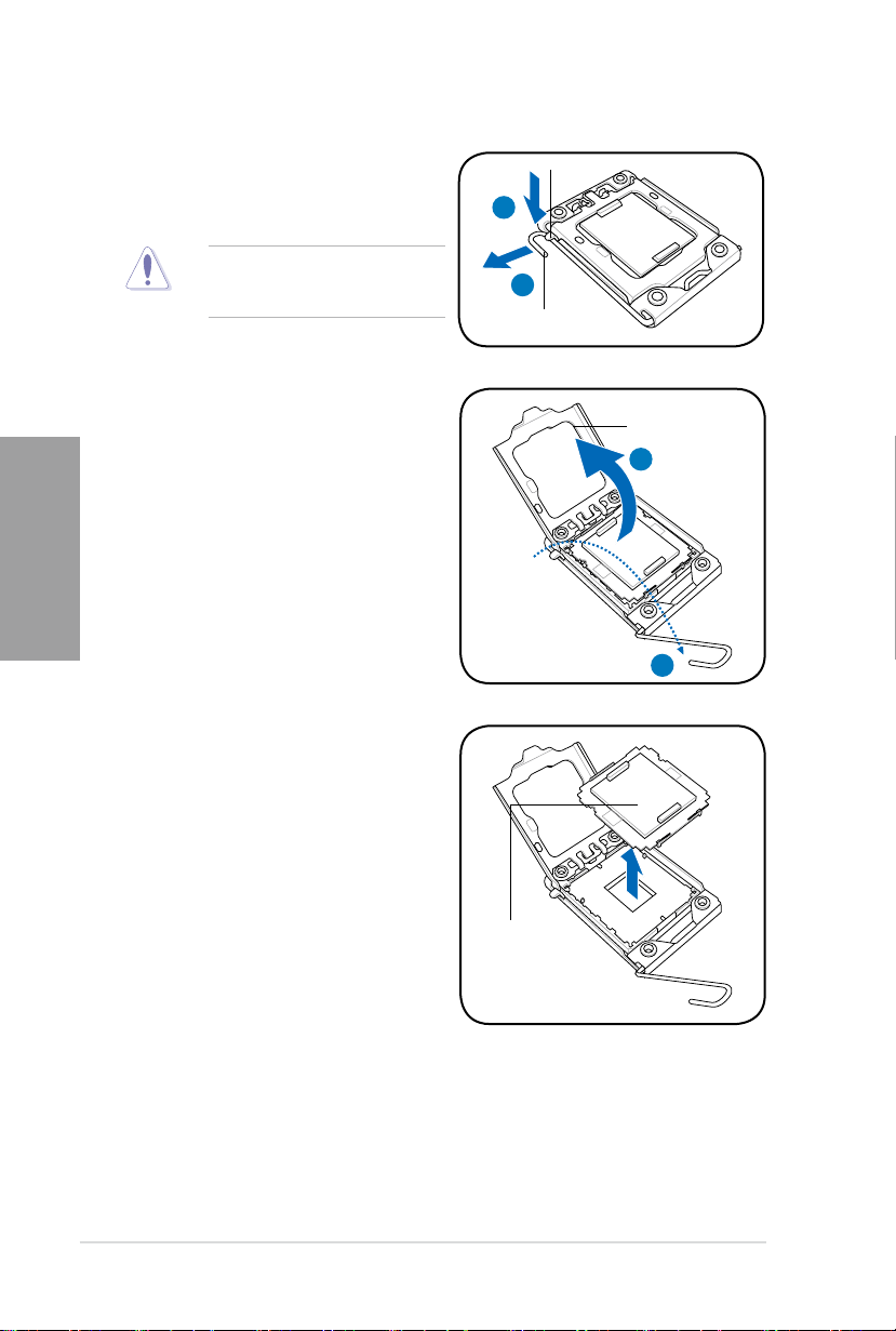
Chapter 2
2. Press the load lever with your thumb
(A), then move it to the left (B) until it is
released from the retention tab.
3. Lift the load lever in the direction of the
arrow to a 135º angle.
4. Lift the load plate with your thumb and
forenger to a 100º angle.
5. Remove the PnP cap from the CPU
socket.
To prevent damage to the socket pins,
do not remove the PnP cap unless
you are installing a CPU.
Retention tab
A
B
Load lever
Load plate
4
3
PnP cap
ASUS P6X58-E PRO 2-7
Chapter 2
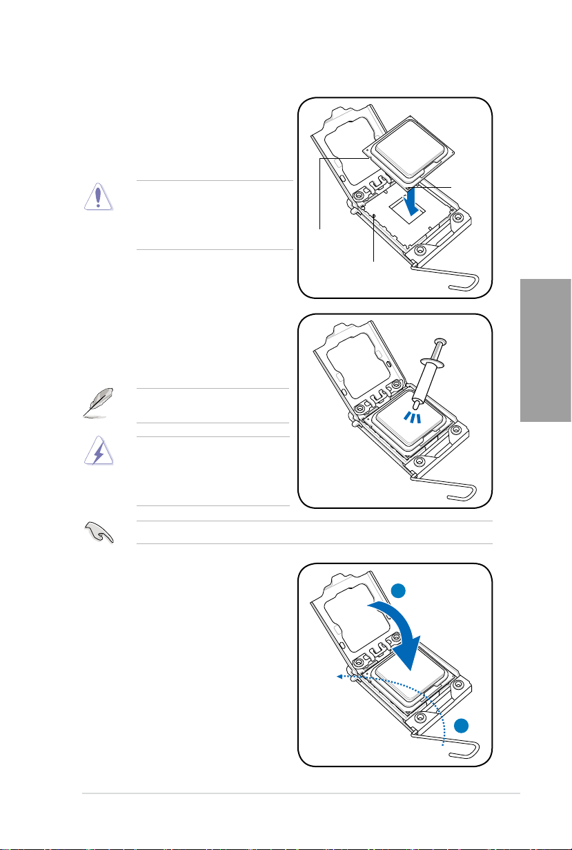
6. Position the CPU over the socket,
ensuring that the gold triangle is on the
bottom-left corner of the socket, and then
t the socket alignment key into the CPU
notch.
The CPU ts in only one correct
orientation. DO NOT force the CPU
into the socket to prevent bending
the connectors on the socket and
damaging the CPU!
7. Apply some Thermal Interface Material
to the exposed area of the CPU that the
heatsink will be in contact with, ensuring
that it is spread in an even thin layer.
CPU notch
Alignment key
Gold
triangle
mark
Some heatsinks come with pre-applied
thermal paste. If so, skip this step.
The Thermal Interface Material is
toxic and inedible. DO NOT eat it. If
it gets into your eyes or touches your
skin, wash it off immediately, and seek
professional medical help.
To prevent contaminating the paste, DO NOT spread the paste with your nger directly.
8. Close the load plate (A), then push
the load lever (B) until it snaps into the
retention tab.
A
B
2-8 Chapter 2: Hardware information
Chapter 2
2.3.2 Installing the CPU heatsink and fan
The Intel® LGA1366 processor requires a specially designed heatsink and fan assembly to
ensure optimum thermal condition and performance.
• When you buy a boxed Intel® processor, the package includes the CPU fan and
heatsink assembly. If you buy a CPU separately, ensure that you use only Intel®-certied
multi-directional heatsink and fan.
• Your Intel® LGA1366 heatsink and fan assembly comes in a push-pin design and
requires no tool to install.
If you purchased a separate CPU heatsink and fan assembly, ensure that the Thermal
Interface Material is properly applied to the CPU heatsink or CPU before you install the
heatsink and fan assembly.
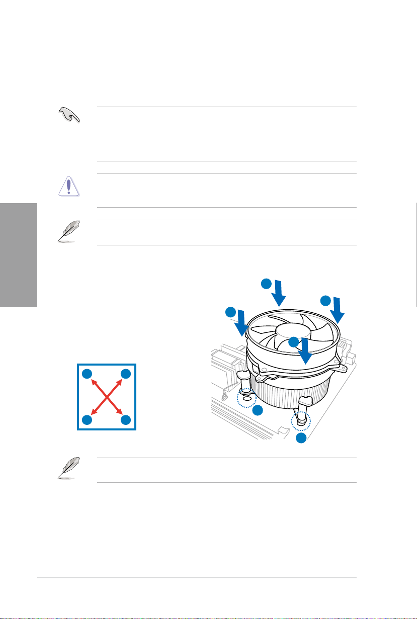
To install the CPU heatsink and fan:
1. Place the heatsink on top of the installed
CPU, ensuring that the four fasteners
match the holes on the motherboard.
2. Push down two fasteners at a time in
a diagonal sequence to secure the
heatsink and fan assembly in place.
Ensure that you have installed the motherboard to the chassis before you install the CPU
fan and heatsink assembly.
A
B
B
A
A
B
B
1
A
1
Orient the heatsink and fan assembly such that the CPU fan cable is closest to the CPU fan
connector.
ASUS P6X58-E PRO 2-9
Chapter 2
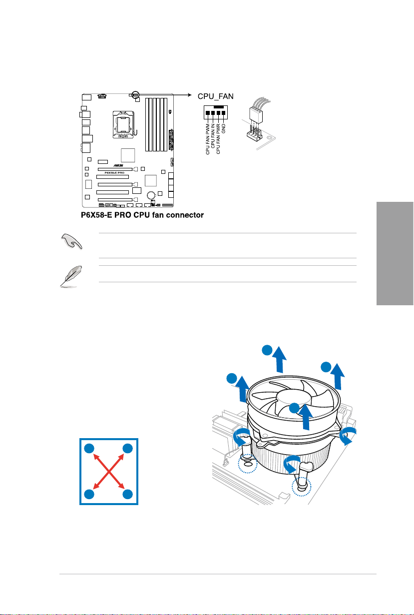
3. Connect the CPU fan cable to the connector on the motherboard labeled CPU_FAN.
DO NOT forget to connect the CPU fan connector! Hardware monitoring errors can occur if
you fail to plug this connector.
Refer to page 2-35 for details.
2.3.3 Uninstalling the CPU heatsink and fan
To uninstall the CPU heatsink and fan:
1. Disconnect the CPU fan cable from the
connector on the motherboard.
2. Rotate each fastener counterclockwise.
B
3. Pull up two fasteners at a time in a
diagonal sequence to disengage the
heatsink and fan assembly from the
motherboard.
A
B
B
A
4. Carefully remove the heatsink and fan assembly from the motherboard.
A
A
B
2-10 Chapter 2: Hardware information
Chapter 2
2.4 System memory
DIMM A1
DIMM B1
DIMM A1
DIMM B1
DIMM C1
DIMM A1
DIMM B1
DIMM A1
DIMM B1
DIMM C1
DIMM A1
DIMM A2
DIMM B2
DIMM B1
DIMM C2
DIMM C1
DIMM A1
DIMM B1
DIMM C1
DIMM A2
DIMM A1
DIMM B1
DIMM C1
DIMM A1
DIMM B1
DIMM C1
DIMM A1
DIMM A2
DIMM B2
DIMM B1
DIMM C2
DIMM C1
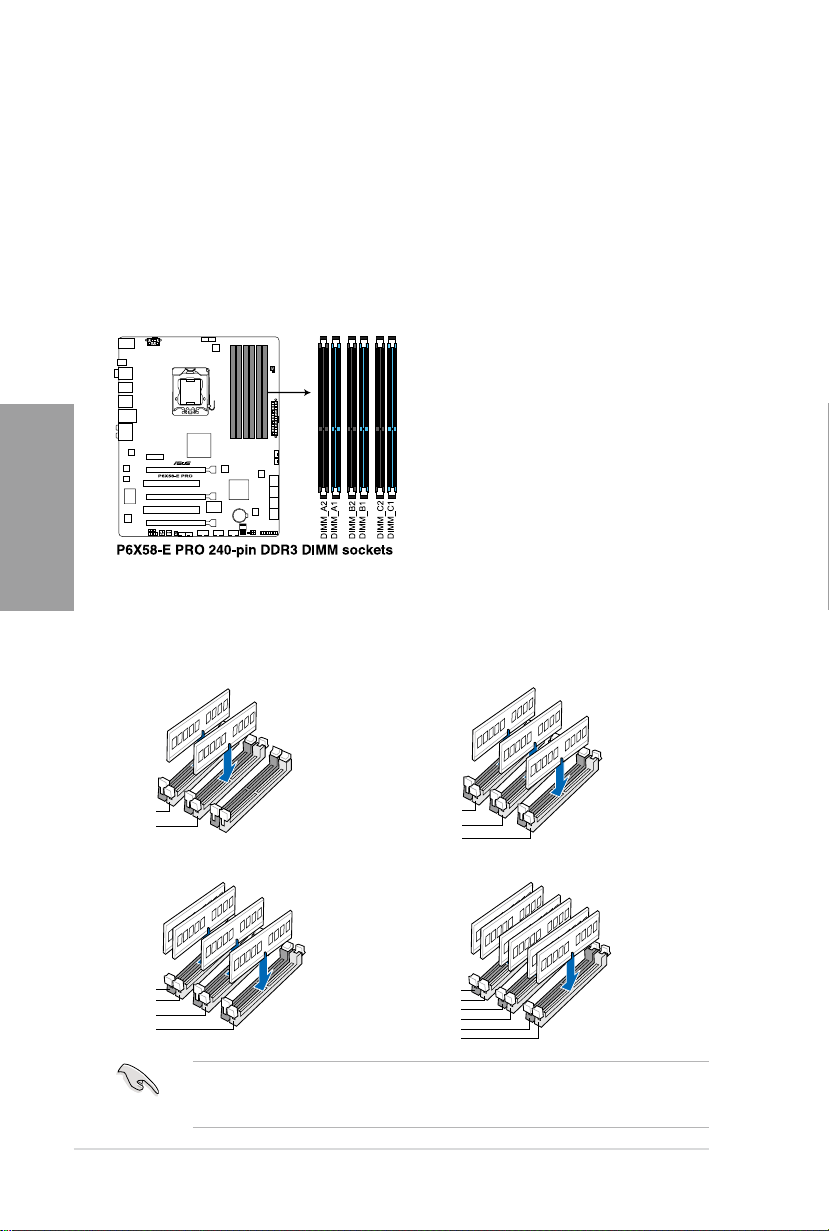
2.4.1 Overview
The motherboard comes with six Double Data Rate 3 (DDR3) Dual Inline Memory Modules
(DIMM) sockets.
A DDR3 module has the same physical dimensions as a DDR2 DIMM but is notched
differently to prevent installation on a DDR2 DIMM socket. DDR3 modules are developed for
better performance with less power consumption.
The gure illustrates the location of the DDR3 DIMM sockets:
Recommended memory congurations
One DIMM:
You may install one memory module in slot A1, B1 or C1 as a single-channel operation.
Two DIMMs (dual-channel operation): Three DIMMs (triple-channel operation):
Four DIMMs (triple-channel operation):
Six DIMMs (triple-channel operation):
Due to Intel CPU spec denition, the system will not boot if only one DIMM is installed
in DIMM slot A2, B2, or C2. Follow the illustrations above for recommended memory
conguration.
 Loading...