

Page 1

P5VDC-TVM
Motherboard
Page 2

E256 9
Firs t E diti o n
Apri l 2 006
Cop y r i ght © 2 0 06 AS U S T eK C O M P U TER I N C . All R i g hts R e s e rved .
No part of this manual, including the products and software described in it, may be reproduced,
transmitted, transcribed, stored in a retrieval system, or translated into any language in any form
or by any means, except documentation kept by the purchaser for backup purposes, without the
express written permission of ASUSTeK COMPUTER INC. (“ASUS”).
Product warranty or service will not be extended if: (1) the product is repaired, modied or
altered, unless such repair, modication of alteration is authorized in writing by ASUS; or (2)
the serial number of the product is defaced or missing.
ASUS PROVIDES THIS MANUAL “AS IS” WITHOUT WARRANTY OF ANY KIND, EITHER
EXPRESS OR IMPLIED, INCLUDING BUT NOT LIMITED TO THE IMPLIED WARRANTIES
OR CONDITIONS OF MERCHANTABILITY OR FITNESS FOR A PARTICULAR PURPOSE.
IN NO EVENT SHALL ASUS, ITS DIRECTORS, OFFICERS, EMPLOYEES OR AGENTS BE
LIABLE FOR ANY INDIRECT, SPECIAL, INCIDENTAL, OR CONSEQUENTIAL DAMAGES
(INCLUDING DAMAGES FOR LOSS OF PROFITS, LOSS OF BUSINESS, LOSS OF USE
OR DATA, INTERRUPTION OF BUSINESS AND THE LIKE), EVEN IF ASUS HAS BEEN
ADVISED OF THE POSSIBILITY OF SUCH DAMAGES ARISING FROM ANY DEFECT OR
ERROR IN THIS MANUAL OR PRODUCT.
SPECIFICATIONS AND INFORMATION CONTAINED IN THIS MANUAL ARE FURNISHED
FOR INFORMATIONAL USE ONLY, AND ARE SUBJECT TO CHANGE AT ANY TIME
WITHOUT NOTICE, AND SHOULD NOT BE CONSTRUED AS A COMMITMENT BY
ASUS. ASUS ASSUMES NO RESPONSIBILITY OR LIABILITY FOR ANY ERRORS OR
INACCURACIES THAT MAY APPEAR IN THIS MANUAL, INCLUDING THE PRODUCTS
AND SOFTWARE DESCRIBED IN IT.
Products and corporate names appearing in this manual may or may not be registered
trademarks or copyrights of their respective companies, and are used only for identication or
explanation and to the owners’ benet, without intent to infringe.
ii
Page 3

Contents
Notices ................................................................................................. v
Safety information .............................................................................. vi
P5VDC-TVM specications summary ..................................................vii
Cha p te r 1: Pro d uc t in t ro d uct i on
1.1 Before you proceed .............................................................. 1-2
1.2 Motherboard overview .......................................................... 1-3
1.2.1 Placement direction ................................................ 1-3
1.2.2 Screw holes ............................................................. 1-3
1.2.3 Motherboard layout ................................................ 1-4
1.2.4 Layout contents ..................................................... 1-5
1.3 Central Processing Unit (CPU) .............................................. 1-6
1.3.1 Installing the CPU .................................................... 1-6
1.3.2 Installing the CPU heatsink and fan ......................... 1-9
1.3.3 Uninstalling the CPU heatsink and fan ...................1-11
1.4 System memory .................................................................. 1-13
1.4.1 DIMM sockets location .......................................... 1-13
1.4.2 Memory Congurations ......................................... 1-13
1.4.3 Installing a DDR2 DIMM ......................................... 1-15
1.4.4 Removing a DDR2 DIMM ........................................ 1-15
1.5 Expansion slots ................................................................... 1-16
1.5.1 Installing an expansion card .................................. 1-16
1.5.2 Conguring an expansion card .............................. 1-16
1.5.3 Interrupt assignments ........................................... 1-17
1.5.4 PCI slots ................................................................ 1-18
1.6 Jumpers .............................................................................. 1-19
1.7 Connectors .........................................................................1-21
1.7.1 Rear panel connectors .......................................... 1-21
1.7.2 Internal connectors ............................................... 1-22
iii
Page 4
Contents
Cha p te r 2: B I OS S et u p
2.1 BIOS setup program .............................................................. 2-2
2.2 BIOS menu screen ................................................................. 2-3
2.3 Standard BIOS Features ........................................................ 2-5
2.4 Advanced BIOS Features ....................................................... 2-9
2.5 Integrated Peripherals ......................................................... 2-11
2.6 Power Management Setup .................................................. 2-15
2.7 PC Health Status ................................................................. 2-17
2.8 Other items ......................................................................... 2-18
iv
Page 5
Notices
Fed er al Co mm un ica ti on s C om mi ssi on S tat em en t
This device complies with Part 15 of the FCC Rules. Operation is subject to
the following two conditions:
•
This device may not cause harmful interference, and
•
This device must accept any interference received including
interference that may cause undesired operation.
This equipment has been tested and found to comply with the limits for a
Class B digital device, pursuant to Part 15 of the FCC Rules. These limits
are designed to provide reasonable protection against harmful interference
in a residential installation. This equipment generates, uses and can radiate
radio frequency energy and, if not installed and used in accordance with
manufacturer’s instructions, may cause harmful interference to radio
communications. However, there is no guarantee that interference will
not occur in a particular installation. If this equipment does cause harmful
interference to radio or television reception, which can be determined by
turning the equipment off and on, the user is encouraged to try to correct
the interference by one or more of the following measures:
•
Reorient or relocate the receiving antenna.
•
Increase the separation between the equipment and receiver.
•
Connect the equipment to an outlet on a circuit different from that to
which the receiver is connected.
•
Consult the dealer or an experienced radio/TV technician for help.
The use of shielded cables for connection of the monitor to the graphics
card is required to assure compliance with FCC regulations. Changes
or modications to this unit not expressly approved by the party
responsible for compliance could void the user’s authority to operate
this equipment.
Can ad ia n D ep ar tme nt o f C om mu nic at io ns St at eme nt
This digital apparatus does not exceed the Class B limits for radio noise
emissions from digital apparatus set out in the Radio Interference
Regulations of the Canadian Department of Communications.
This class B digital apparatus complies with Canadian
ICES-003.
v
Page 6
Safety information
Ele ct ri cal s af ety
•
To prevent electrical shock hazard, disconnect the power cable from
the electrical outlet before relocating the system.
•
When adding or removing devices to or from the system, ensure that
the power cables for the devices are unplugged before the signal
cables are connected. If possible, disconnect all power cables from the
existing system before you add a device.
•
Before connecting or removing signal cables from the motherboard,
ensure that all power cables are unplugged.
•
Seek professional assistance before using an adapter or extension
cord. These devices could interrupt the grounding circuit.
•
Make sure that your power supply is set to the correct voltage in your
area. If you are not sure about the voltage of the electrical outlet you
are using, contact your local power company.
•
If the power supply is broken, do not try to fix it by yourself. Contact
a qualified service technician or your retailer.
Ope ra ti on sa fe ty
•
Before installing the motherboard and adding devices on it, carefully
read all the manuals that came with the package.
•
Before using the product, make sure all cables are correctly connected
and the power cables are not damaged. If you detect any damage,
contact your dealer immediately.
•
To avoid short circuits, keep paper clips, screws, and staples away from
connectors, slots, sockets and circuitry.
•
Avoid dust, humidity, and temperature extremes. Do not place the
product in any area where it may become wet.
•
Place the product on a stable surface.
•
If you encounter technical problems with the product, contact a
qualified service technician or your retailer.
The symbol of the crossed out wheeled bin indicates that the product
(electrical and electronic equipment) should not be placed in municipal
waste. Check local regulations for disposal of electronic products.
vi
Page 7
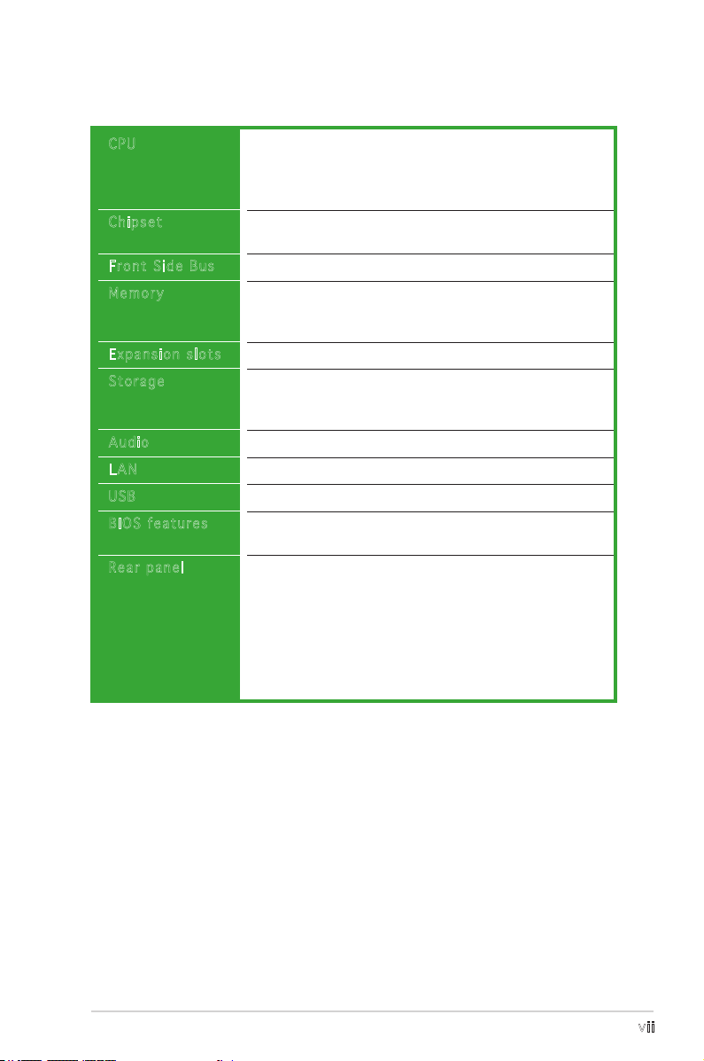
P5VDC-TVM specications summary
CPU
Chipset
Front Side Bus
Memory
Expansion slots
Storage
Audio
LAN
USB
BIOS features
Rear panel
LGA775 socket for Intel® Pentium® 4/Celeron processor
Compatible with Intel® Mainstream/Value FMB
processors
Supports Intel® Hyper-Threading Technology
Northbridge: VIA P4M800 PRO
Southbridge: VIA VT8237R Plus
800/533 MHz
2 x 240-pin DIMM sockets support unbufferred and
non-ECC
533 MHz DDR memory modules
3 x PCI slots
VIA VT8237R Plus Southbridge supports:
- 4 x Ultra ATA 133/100/66 hard disk drives
- 2 x Serial ATA hard disk drives
Realtek® ALC655 6-channel CODEC
Realtek® RTL 8110C 10/100 Mbps LAN controller
Supports up to 8 USB 2.0 ports
4 MB LPC Flash ROM, Award BIOS, Green, PnP, DMI, WfM
2.0, ACPI 2.0a, SM BIOS 2.3
1 x PS/2 mouse port
1 x Parallel port
1 x LAN (RJ-45) port
6-channel audio ports
4 x USB 2.0 ports
1 x VGA port
1 x Serial port
1 x PS/2 keyboard port
(continued on the next page)
vii
Page 8
P5VDC-TVM specications summary
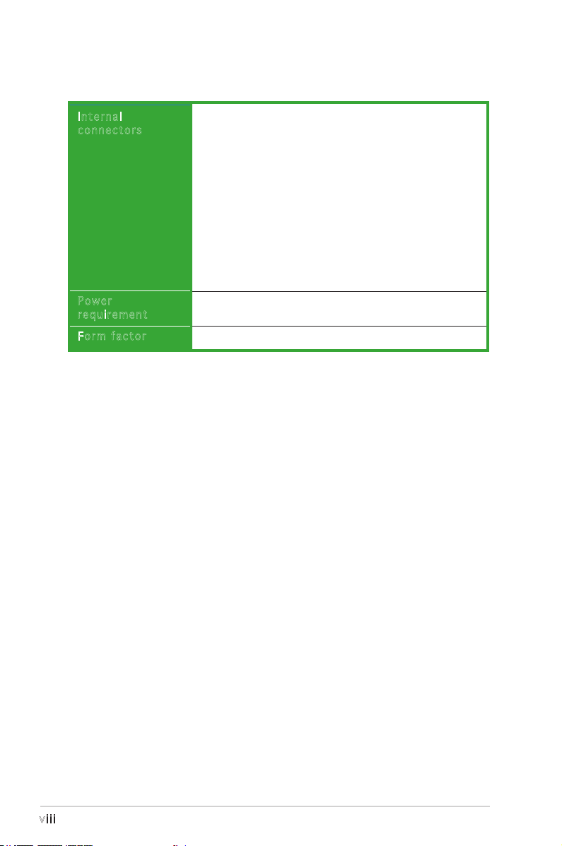
Internal
connectors
Power
requirement
Form factor
1 x Floppy disk drive connector
2 x IDE connectors
2 x Serial ATA connectors
1 x CPU fan connector
1 x Chassis fan connector
4 x USB 2.0 connectors
1 x 20-pin ATX power connector
1 x 4-pin ATX 12 V power connector
1 x Front panel audio connector
1 x CD/AUX audio connector
1 x S/PDIF Out connector
1 x Serial port connector
System panel connector
ATX power supply (with 20-pin and 4-pin 12 V plugs)
ATX 12 V 2.0 compliant
Micro ATX form factor: 9.6 in x 9.0 in (24.5 cm x 23.0 cm)
*Specications are subject to change without notice.
viii
Page 9

This chapter describes the motherboard
features and the new technologies
it supports.
introduction
Product
1
1-1ASUS P5VDC-TVM
Page 10
1.1 Before you proceed
P5VDC-TVM Onboard LED
SB_PWR
ON
Standby
Power
OFF
Powered
Off
P5VDC-TVM
®
Take note of the following precautions before you install components into
the system.
•
Unplug the power cord from the wall socket before touching any
component.
•
Use a grounded wrist strap or touch a safely grounded object or
a metal object, such as the power supply case, before handling
components to avoid damaging them due to static electricity.
•
Hold components by the edges to avoid touching the ICs on them.
•
Whenever you uninstall any component, place it on a grounded
antistatic pad or in the bag that came with the component.
•
Before you install or remove any component, ensure that the ATX
power supply is switched off or the power cord is detached from
the power supply. Failure to do so may cause severe damage to the
motherboard, peripherals, and/or components.
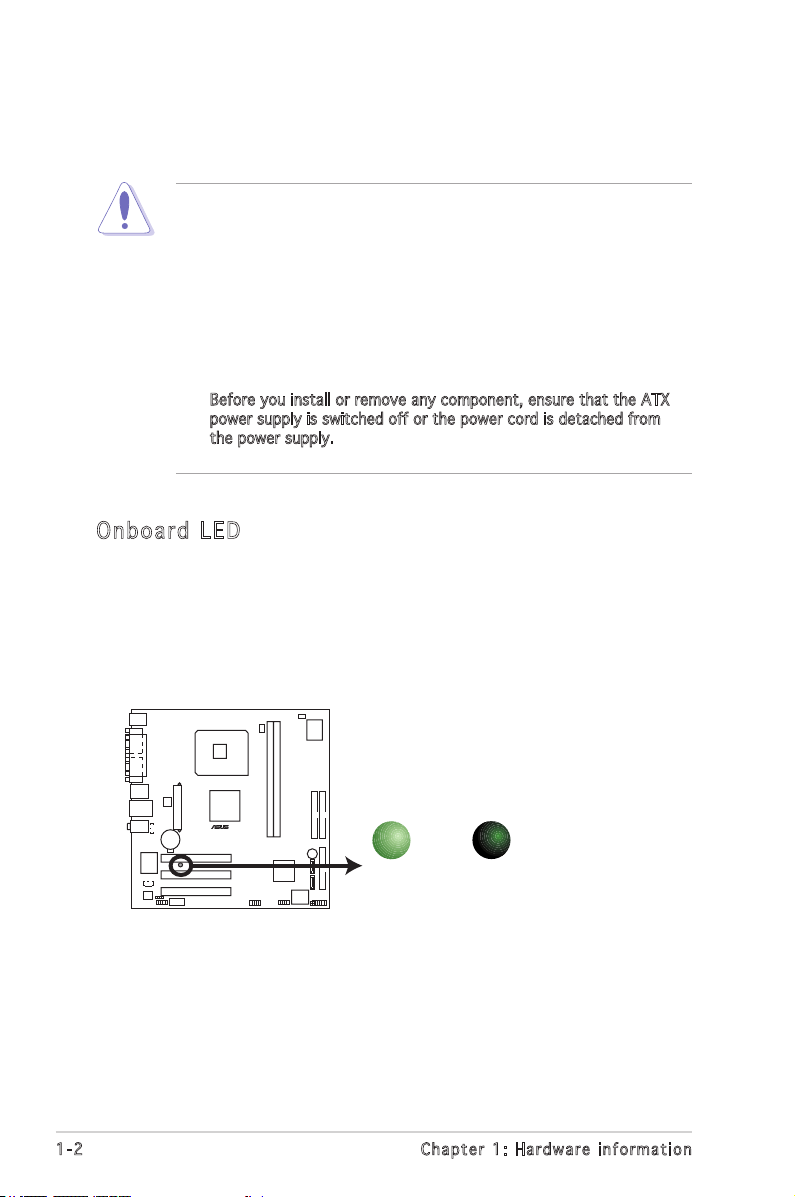
Onb oa rd LE D
The motherboard comes with a standby power LED that lights up to
indicate that the system is ON, in sleep mode, or in soft-off mode.
This is a reminder that you should shut down the system and unplug
the power cable before removing or plugging in any motherboard
component. The illustration below shows the location of the onboard
LED.
1-2 Chapter 1: Hardware information
Page 11
1.2 Motherboard overview
P5VDC-TVM
®
Before you install the motherboard, study the conguration of your chassis
to ensure that the motherboard ts into it.
Make sure to unplug the power cord before installing or removing the
motherboard. Failure to do so can cause you physical injury and damage
motherboard components.
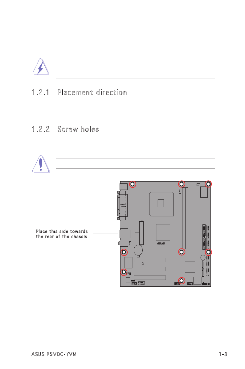
1.2 .1 Pla ce me nt di re cti on
When installing the motherboard, make sure that you place it into the
chassis in the correct orientation. The edge with external ports goes to the
rear part of the chassis as indicated in the image below.
1.2 .2 Scr ew h ole s
Place eight (8) screws into the holes indicated by circles to secure the
motherboard to the chassis.
Do not overtighten the screws! Doing so can damage the motherboard.
Pla c e this s i d e tow a r d s
the r e ar of t h e cha s s i s
1-3ASUS P5VDC-TVM
Page 12
F_PANEL
FWP
CLRTC1
LGA775
DDR2 DIMM_A1 (128 bit,240-pin module)
DDR2 DIMM_B1 (128 bit,240-pin module)
Super
I/O
VIA VT837R
Plus
VIA P4M800
PRO
PCI1
PCI2
PCI3
RTL8100C
4Mb BIOS
BUZZER
CR2032 3V
Lithium Cell
CMOS Power
ATXPWR
ATX12V
ALC655
PRI_IDE
SEC_IDE
FLOPPY
USB78
USB56
SPDIF_OUT
FP_AUDIO
AUX
CD
SB_PWR
CHA_FAN
CPU_FAN
SATA2
SATA1
Below:
Center/Subwoofer
Center:
Side Speaker Out
Top:Rear Speaker Out
LAN_USB34
USB1
USB2
COM1
PARALLEL PORT
VGA
PS/2KBMS
T: Mouse
B: Keyboard
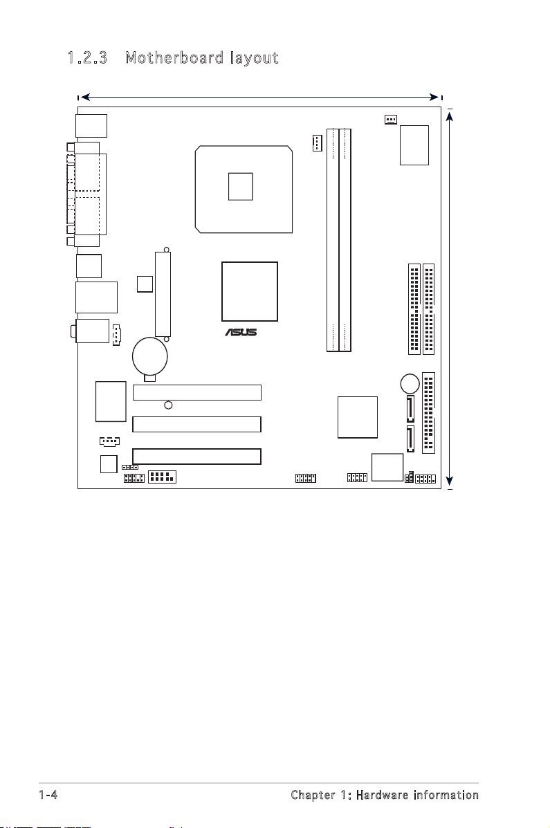
24.5cm (9.6in)
P5VDC-TVM
22.9cm (9.0in)
®
COM1
1.2 .3 Mot he rb oar d la you t
1-4 Chapter 1: Hardware information
Page 13
1.2 .4 Lay ou t con te nt s
Slo t s Pag e
1. PCI slots 1-20
Jum p e r s Pag e
1. Clear RTC RAM (3-pin CLRTC) 1-21
2 Flash Write Protection (2-pin FWP) 1-22
Rea r p anel c o n n ecto r s Pag e
1. PS/2 mouse port (green) 1-23
2. Parallel port 1-23
3. LAN (RJ-45) port 1-23
4. Line In port (light blue) 1-23
5. Line Out port (lime) 1-23
6. Microphone port (pink) 1-23
7. USB 2.0 ports 3 and 4 1-24
8. USB 2.0 ports 1 and 2 1-24
9. Video Graphics Adapter (VGA) port 1-24
10. Serial port 1-24
11. PS/2 keyboard port (purple) 1-24
Int e r n a l co n n e c tors Pag e
1. Floppy disk drive connector (34-1 pin FLOPPY) 1-24
2. IDE connector (40-1 pin PRI_IDE, SEC_IDE) 1-25
3. Serial ATA connectors (7-pin SATA1, SATA2) 1-26
4. CPU and Chassis Fan connectors (4-pin CPU_FAN, 3-pin CHA_FAN) 1-27
5. USB connectors (10-1 pin USB56, USB78) 1-28
6. ATX power connectors (20-pin ATXPWR, 4-pin ATX12V) 1-29
7. Front panel audio connector (10-1 pin FP_AUDIO) 1-30
8. Serial port connector (10-1 pin COM2) 1-30
9. Internal audio connector (4-pin CD, AUX) 1-31
10. Digital audio connector (4-1 pin SPDIF_OUT) 1-31
11. System panel connector (10-1 pin PANEL) 1-34
System power LED (2-pin PLED)
Hard disk drive activity LED (2-pin IDE_LED)
Power button/soft-off button (2-pin PWRSW)
Reset button (2-pin RESET)
1-5ASUS P5VDC-TVM
Page 14
P5DC-TVM CPU Socket 775
P5VDC-TVM
®
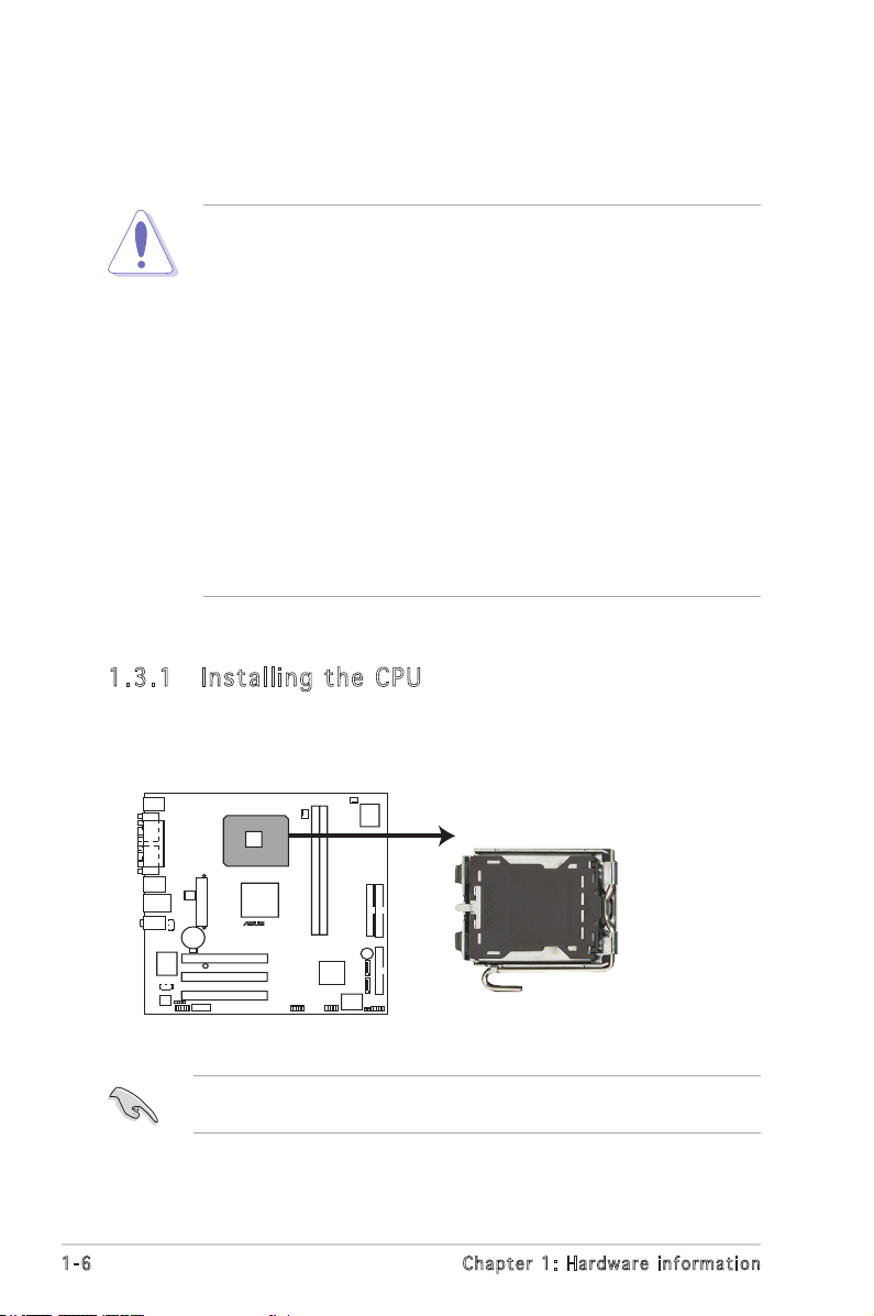
1.3 Central Processing Unit (CPU)
The motherboard comes with a surface mount LGA775 socket designed for
the Intel® Pentium® 4 processor in the 775-land package.
• Your boxed Intel® Pentium® 4 LGA775 processor package should
come with installation instructions for the CPU, heatsink, and the
retention mechanism. If the instructions in this section do not
match the CPU documentation, follow the latter.
• Upon purchase of the motherboard, make sure that the PnP cap
is on the socket and the socket contacts are not bent. Contact
your retailer immediately if the PnP cap is missing, or if you
see any damage to the PnP cap/socket contacts/motherboard
components. ASUS will shoulder the cost of repair only if the
damage is shipment/transit-related.
• Keep the cap after installing the motherboard. ASUS will process
Return Merchandise Authorization (RMA) requests only if the
motherboard comes with the cap on the LGA775 socket.
• The product warranty does not cover damage to the socket
contacts resulting from incorrect CPU installation/removal, or
misplacement/loss/incorrect removal of the PnP cap.
1.3 .1 Ins ta ll ing t he CP U
To install a CPU:
1. Locate the CPU socket on the motherboard.
Before installing the CPU, make sure that the socket box is facing
towards you and the load lever is on your left.
1-6 Chapter 1: Hardware information
Page 15
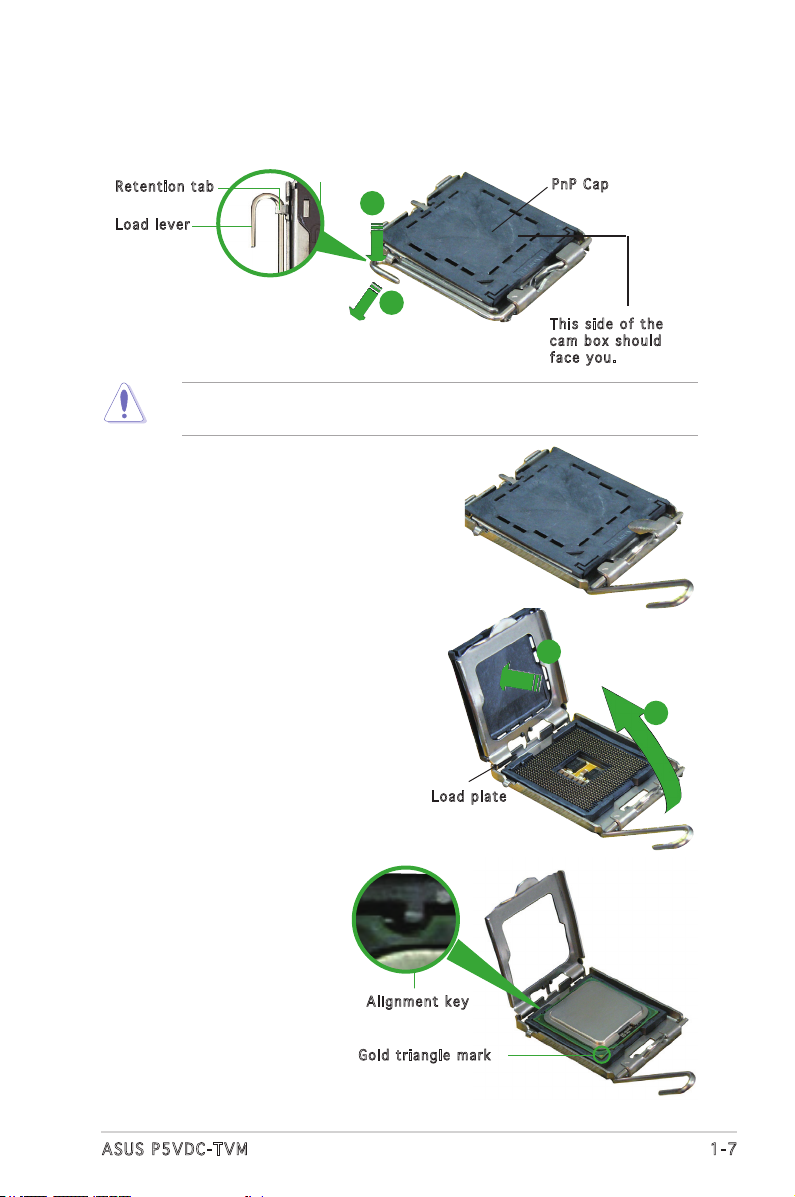
2. Press the load lever with your thumb (A) and move it to the left (B)
until it is released from the retention tab.
Ret e n t ion t a b
Loa d l ever
To prevent damage to the socket pins, do not remove the PnP cap
unless you are installing a CPU.
A
B
3. Lift the load lever in the direction
of the arrow to a 135º angle.
4. Lift the load plate with your
thumb and forenger to a 100º
angle (A), then push the PnP cap
from the load plate window to
remove (B).
PnP C a p
Thi s s ide o f t he
cam b o x sho u l d
fac e y ou.
B
A
5. Position the CPU on the
socket, making sure that
the gold triangle xes on
the bottom-left corner of
the socket. The socket
alignment keys should t
into the CPU notches.
Loa d p late
Ali g n m ent k e y
Gol d t riang l e mark
1-7ASUS P5VDC-TVM
Page 16
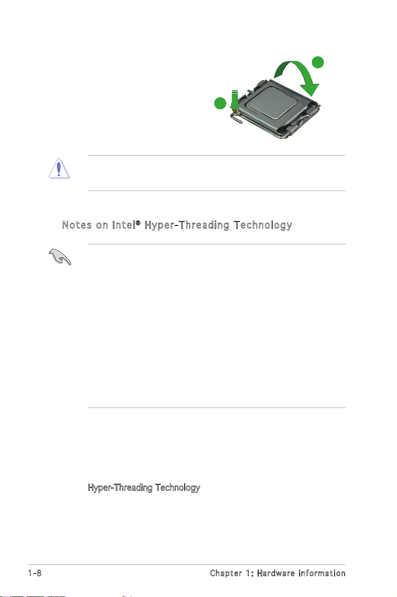
6. Close the load plate (A), then
push the load lever (B) until it
snaps into the retention tab.
B
The CPU ts in only one correct orientation. DO NOT force the CPU
into the socket to prevent benting the connectors on the socket and
damaging the CPU.
Not e s o n I n te l® Hy p er - Thr e ad i ng T ec h nol o gy
• This motherboard supports Intel® Pentium® 4 CPUs in the 775-land
package with Hyper-Threading Technology.
• Hyper-Threading Technology is supported under Windows® XP/2003
Server and Linux 2.4.x (kernel) and later versions only. Under Linux,
use the Hyper-Threading compiler to compile the code. If you are
using any other operating systems, disable the Hyper-Threading
Technology item in the BIOS to ensure system stability and
performance.
• Installing Windows
recommended.
• Make sure to enable the Hyper-Threading Technology item in BIOS
before installing a supported operating system.
• For more information on Hyper-Threading Technology, visit
www.intel.com/info/hyperthreading.
®
XP Service Pack 1 or later version is
A
To use the Hyper-Threading Technology on this motherboard:
1. Install an Intel® Pentium® 4 CPU that supports Hyper-Threading
Technology.
2. Power up the system and enter the BIOS Setup (see Chapter 2: BIOS
setup). Under the Advanced BIOS Features Menu, make sure that the
item Hyper-Threading Technology is set to Enabled. The item appears
only if you installed a CPU that supports Hyper-Threading Technology.
3. Reboot the computer.
1-8 Chapter 1: Hardware information
Page 17
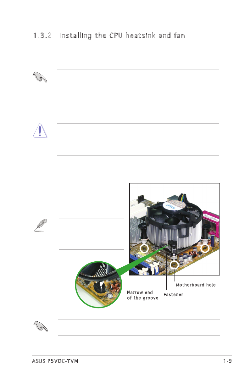
1.3 .2 Ins ta ll ing t he CP U he ats in k and f an
The Intel® Pentium® 4 LGA775 processor requires a specially designed
heatsink and fan assembly to ensure optimum thermal condition and
performance.
• Install the motherboard to the chassis before you install the CPU fan
and heatsink assembly.
• When you buy a boxed Intel® Pentium® 4 processor, the package
includes the CPU fan and heatsink assembly.
• Your Intel® Pentium® 4 LGA775 heatsink and fan assembly comes in
a push-pin design and requires no tool to install it.
• Make sure that you use Intel®-certied multi-directional heatsink and
fan only.
• Make sure that you have installed the motherboard to the chassis
before you install the CPU fan and heatsink assembly.
To install the CPU heatsink and fan:
1. Place the heatsink on top of the
installed CPU, and make sure
that the four fasteners match
the holes on the motherboard.
Orient the heatsink and fan
assembly such that the CPU
fan cable is closest to the
CPU fan connector.
Mot h e r board h o le
Nar r o w end
of t h e groo v e
Make sure to orient each fastener with the narrow end of the groove
pointing outward. (The photo shows the groove shaded for emphasis.)
Fas t e n er
1-9ASUS P5VDC-TVM
Page 18

2. Push down two fasteners at
P5VDC-TVM CPU FAN Connector
P5VDC-TVM
®
CPU_FAN
GND
CPU FAN PWR
CPU FAN IN
CPU FAN PWM
a time in a diagonal sequence
to secure the heatsink and
fan assembly in place.
B
A
A
A
B
B
A
B
3. Connect the CPU fan cable to the connector on the motherboard
labeled CPU_FAN.
Do not forget to connect the CPU fan connector! Hardware monitoring
errors can occur if you fail to plug this connector.
1-10 Chapter 1: Hardware information
Page 19

1.3 .3 Uni ns ta lli ng t he CP U hea ts in k a nd f an
To uninstall the CPU heatsink and fan:
1. Disconnect the CPU fan
cable from the connector
on the motherboard.
2. Rotate each fastener
counterclockwise.
3. Pull up two fasteners at a
time in a diagonal sequence
to disengage the heatsink
and fan assembly from the
motherboard.
A
B
A
B
B
A
B
A
1-11ASUS P5VDC-TVM
Page 20

4. Remove the heatsink and
fan assembly from the
motherboard.
5. Rotate each fastener
clockwise to reset the
orientation.
Nar r o w end o f the g r o o ve
When reset, each
fastener should be
oriented as shown,
with the narrow groove
directed outward.
1-12 Chapter 1: Hardware information
Page 21

1.4 System memory
P5VDC-TVM DDR2 DIMM Sockets
DDR2_A1
DDR2_B1
P5VDC-TVM
®
1.4 .1 DIM M so cke ts l oca ti on
The motherboard comes with two 240-pin Double Data Rate 2 (DDR2).
The following gure illustrates the location of the sockets:
1.4 .2 Mem or y Con fi gu rat io ns
You may install 256 MB, 512 MB and 1 GB unbuffered and non-ECC DDR2
DIMMs into the DIMM sockets using the memory congurations in this
section.
• Always install DIMMs with the same CAS latency. For optimum
compatibility, it is recommended that you obtain memory
modules from the same vendor. Refer to the DDR2 Qualied
Vendors List on the next page for details. Visit the system
builder’s website for the latest DDR2 Qualied Vendors List.
• Due to chipset resource allocation, the system may detect
less than 2 GB system memory when you installed two 1 GB
DDR2 memory modules.
• This motherboard does not support memory modules made
up of 128 Mb chips or double sided x16 memory modules.
1-13ASUS P5VDC-TVM
Page 22

DDR 2 ( 5 33 M Hz) Qu a lif i ed Ven d or s Li s t
Size Vendor Model Brand Side(s) Component DIMM supporpt
512MB Hynix HYMP564U64AP8-C3 Hynix SS HY5PS12821A •
512MB Hynix HYMP564U64AP8-Y4 AA Hynix SS HY5PS12821A •
256MB Inneon HYS64T32000HU-3.7-A N/A SS HYB18T512160AF-3.7 •
256MB Inneon HYS64T32000HU-3.7-B N/A SS HYB18T5121608BF-3.7 •
512MB Inneon HYS64000GU-3.7-A HY SS HYB18T512 •
512MB Inneon HYS64T64000GU-3.7-A N/A SS HYB18T512800AC37 •
512MB Inneon HYS64T64000HU-3.7-A N/A SS HYB18T512800AF37 •
1024MB Inneon HYS64T128020HU-3.7-A N/A DS HYB18T512800AF37 •
2048MB Inneon HYS64T256020HU-3.7-A N/A DS HYB18T1G800AF-3.7 •
512MB MDT M512-533-8 MDT SS 18D51280D-3.7 •
256MB Samsung M378T3253FG0-CD5 Samsung SS K4T560830QF-GC05 •
256MB Samsung M378T3253FG0-CCC Samsung SS K4T560830QF-GCCC •
256MB Samsung M378T3253FG0-CD5 Samsung SS K4T56083QF-GCD5 •
512MB Samsung M378T6553BG0-CD5 Samsung SS K4T51083QB-GCD5 •
512MB Samsung M378T6453FG0-CD5 Samsung DS K4T56083QF-GCD5 •
1024MB Samsung M378T2953BG0-CD5 Samsung DS K4T51083QB-GCD5 •
512MB NANYA NT512T64U88A0F-37B NANYA SS NT5TU64M8AF-37B •
256MB SimpleTech M2GSP2F3G3110A9B0E SimpleTech SS 858S032F25A •
512MB ELPIDA EBE51UD8ABFA-5C-E ELPIDA SS E5108AB-5C-E •
512MB Kingston KVR533D2N4/512 N/A DS HY5PS56821F-C4 •
1024MB Kingston KVR533D2N4/1G N/A DS D6408TE7BL-37 •
2048MB Kingston KVR533D2N4/2G N/A DS E1108AA-5C-E •
256MB Micron MT8HTF3264AY-53EB3 Micron SS 4FBIID9CHM •
512MB Micron MT16HTF6464AY-53EB2 Micron DS 4FBIID9CHM •
SS - Single-sided
DS - Double-sided
Visit the system builder’s website for the latest DDR2-533 Qualied
Vendors List.
1-14 Chapter 1: Hardware information
Page 23

1.4 .3 Ins ta ll ing a D DR2 D IM M
Unplug the power supply before inserting or removing DIMMs or other
system components. Failure to do so can cause severe damage to both
the motherboard and the components.
To install a DDR2 DIMM:
1. Unlock a DDR2 DIMM socket
by pressing the retaining
clips outward.
2. Align a DIMM on the socket
such that the notch on the
DIMM matches the break on
1
the socket.
3. Firmly insert the DIMM into
the socket until the retaining
clips snap back in place and
the DIMM is properly seated.
• A DDR2 DIMM is keyed with a notch so that it ts in only one
direction. Do not force a DIMM into a socket to avoid damaging the
DIMM.
• The DDR2 DIMM sockets do not support DDR DIMMs. DO not install
DDR DIMMs to the DDR2 DIMM sockets.
1.4 .4 Rem ov in g a D DR 2 D IM M
Follow these steps to remove a DDR2 DIMM.
1. Simultaneously press the
retaining clips outward to
unlock the DIMM.
3
DDR 2 D IMM n o t c h
Unl o c k ed re t a i ning c l i p
2
2
Support the DIMM lightly
with your ngers when
pressing the retaining
clips. The DIMM might get
damaged when it ips out
with extra force.
1
2. Remove the DIMM from the socket.
1
DDR 2 D IMM n o t c h
1-15ASUS P5VDC-TVM
Page 24

1.5 Expansion slots
In the future, you may need to install expansion cards. The following
sub-sections describe the slots and the expansion cards that they support.
Make sure to unplug the power cord before adding or removing
expansion cards. Failure to do so may cause you physical injury and
damage motherboard components.
1.5 .1 Ins ta ll ing a n ex p an si on ca rd
To install an expansion card:
1. Before installing the expansion card, read the documentation that
came with it and make the necessary hardware settings for the card.
2. Remove the system unit cover (if your motherboard is already
installed in a chassis).
3. Remove the bracket opposite the slot that you intend to use. Keep
the screw for later use.
4. Align the card connector with the slot and press rmly until the card is
completely seated on the slot.
5. Secure the card to the chassis with the screw you removed earlier.
6. Replace the system cover.
1.5 .2 Con fi gu rin g an e x pa ns io n c ar d
After installing the expansion card, congure it by adjusting the software
settings.
1. Turn on the system and change the necessary BIOS settings, if any.
See Chapter 2 for information on BIOS setup.
2. Assign an IRQ to the card. Refer to the tables on the next page.
3. Install the software drivers for the expansion card.
1-16 Chapter 1: Hardware information
Page 25

1.5 .3 Int er ru pt as si gnm en ts
Sta n da r d i n te r rup t a s sig n me n ts
IRQ Pri o r i ty S t anda r d F unct i o n
0 1 System Timer
1 2 Keyboard Controller
2 - Re-direct to IRQ#9
3 11 Communications Port (COM2)*
4 12 Communications Port (COM1)*
5 13 IRQ holder for PCI steering*
6 14 Floppy Disk Controller
7 15 Printer Port (LPT1)*
8 3 System CMOS/Real Time Clock
9 4 IRQ holder for PCI steering*
10 5 IRQ holder for PCI steering*
11 6 IRQ holder for PCI steering*
12 7 PS/2 Compatible Mouse Port*
13 8 Numeric Data Processor
14 9 Primary IDE Channel
15 10 Secondary IDE Channel
* T h e s e IRQ s a re us u a l l y av a i l a ble f o r ISA o r P CI d e v i c es.
IRQ as s ign m en t s f o r t his mo t her b oa r d
A B C D E F G H
PCI slot 1 shared — — — — — — —
PCI slot 2 — shared — — — — — —
PCI slot 3 — — shared — — — —
Onboard USB controller 0-1 shared — — — — — — —
Onboard USB controller 2-3 shared — — — — — — —
Onboard USB controller 4-5 — shared — — — — — —
Onboard USB controller 6-7 — shared — — — — — —
Onboard USB 2.0 controller — — shared — — — — —
Onboard AC `97 Audio — — shared — — — — —
Onboard PCI LAN (10/100 Mbps) — — — — shared — — —
Onboard PCI 1394 — — — — — shared — —
AGP Slot shared — — — — — — —
When using PCI cards on shared slots, ensure that the drivers support
“Share IRQ” or that the cards do not need IRQ assignments; otherwise,
conicts will arise between the two PCI groups, making the system
unstable and the card inoperable.
1-17ASUS P5VDC-TVM
Page 26
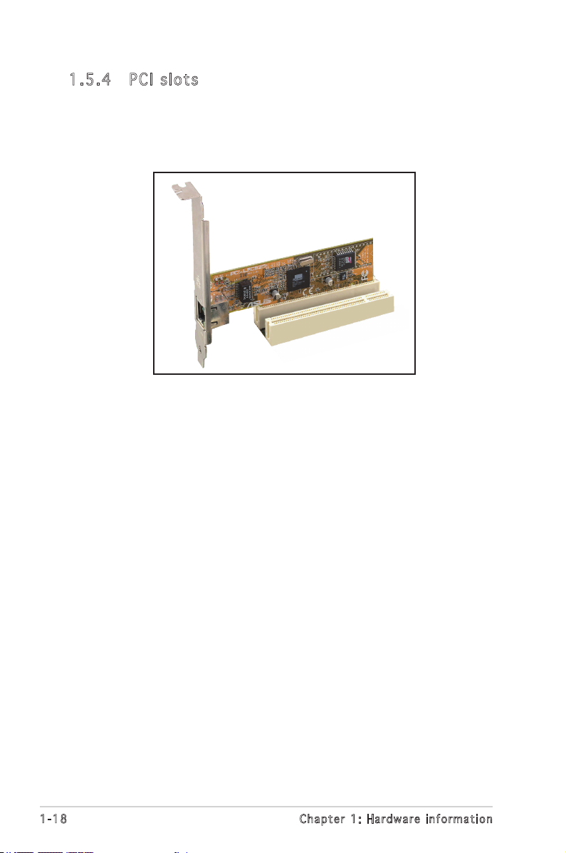
1.5 .4 PCI s lo ts
This motherboard has three PCI slots. The PCI slots support cards such
as a LAN card, SCSI card, USB card, and other cards that comply with PCI
specications. The gure shows a LAN card installed on a PCI slot.
1-18 Chapter 1: Hardware information
Page 27
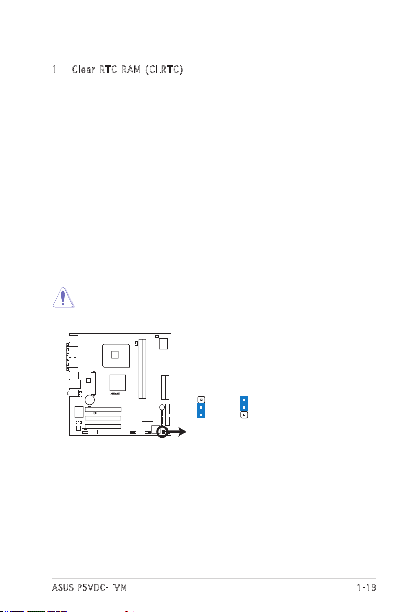
1.6 Jumpers
P5VDC-TVM Clear RTC RAM
CLRTC
Normal Clear CMOS
(Default)
1
2
2
3
P5VDC-TVM
®
1. C l e a r RT C R AM ( C L R TC)
This jumper allows you to clear the Real Time Clock (RTC) RAM in
CMOS. You can clear the CMOS memory of date, time, and system
setup parameters by erasing the CMOS RTC RAM data. The onboard
button cell battery powers the RAM data in CMOS, which include
system setup information such as system passwords.
To erase the RTC RAM:
1. Turn OFF the computer and unplug the power cord.
2. Remove the onboard battery.
3. Move the jumper cap from pins 1-2 (default) to pins 2-3. Keep
the cap on pins 2-3 for about 5~10 seconds, then move the cap
back to pins 1-2.
4. Re-install the battery.
5. Plug the power cord and turn ON the computer.
6. Hold down the <Del> key during the boot process and enter BIOS
setup to re-enter data.
Except when clearing the RTC RAM, never remove the cap on CLRTC
jumper default position. Removing the cap will cause system boot failure!
1-19ASUS P5VDC-TVM
Page 28

2. F l a s h Wr i t e Pro t e c tion ( F WP)
P5VDC-TVM BIOS_WP
(Default)
FWP
WRITE ENABLE WRITE PROTECT
P5VDC-TVM
®
Place the jumper cap on this jumper to write protect the BIOS. If you
need to update your BIOS, remove the jumper cap.
A warning message “Please make sure whether lockout jumper is set to
correct or not.” appears when you ash the BIOS with the jumper cap.
Remove the jumper cap before you update your BIOS.
1-20 Chapter 1: Hardware information
Page 29
1.7 Connectors
1
11 7
2 3
10
4
5
6
9
8
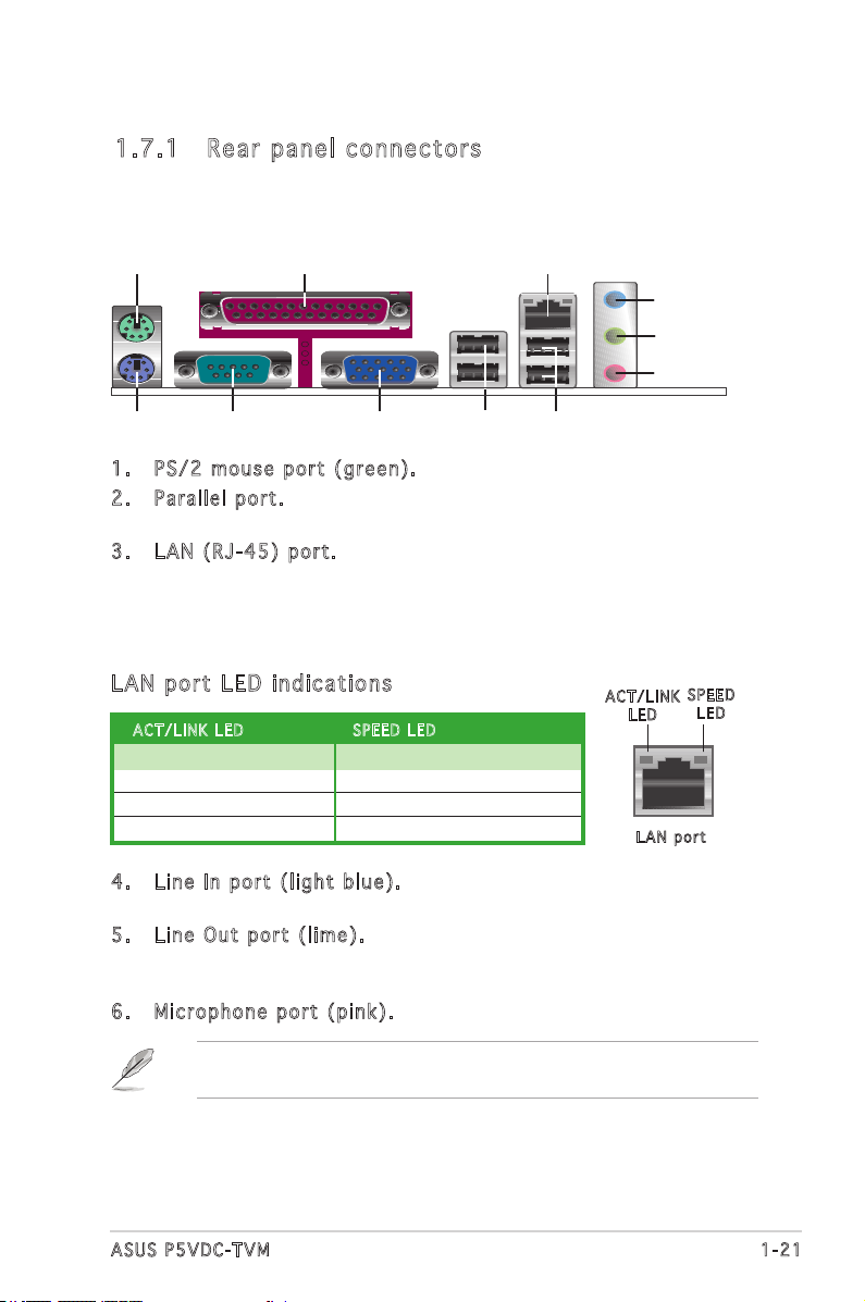
1.7 .1 Rea r pa nel c on nec to rs
1. P S / 2 mou s e port ( g reen ) . This port is for a PS/2 mouse.
2. P a r a llel p o rt. This 25-pin port connects a parallel printer, a scanner,
or other devices.
3. L A N (RJ- 4 5 ) por t . This port allows 10/100 Mbps connection to a
Local Area Network (LAN) through a network hub. Refer to the table
below for the LAN port LED indications.
The optional Gigabit LAN controller allows connection to the Local
Area Network (LAN) through a network hub.
LAN po r t L E D i ndi c at i ons
ACT / L I NK LE D S P EED L E D
Status Description Status Description
OFF No link OFF 10Mbps connection
GREEN Linked ORANGE 100Mbps connection
BLINKING Acting GREEN 1Gbps connection
4. L i n e In p o r t (l i g h t bl u e ) . This port connects a tape, CD, DVD
player, or other audio sources.
5. L i n e Out p o rt ( l i m e). This port connects a headphone or a
speaker. In 4-channel, and 6-channel conguration, the function of this
port becomes Front Speaker Out.
6. M i c r opho n e port ( p ink) . This port connects a microphone.
Refer to the audio conguration table on the next page for the function
of the audio ports with 6-channel conguration.
ACT / L I NK
LED
LAN p o rt
SPE E D
LED
1-21ASUS P5VDC-TVM
Page 30
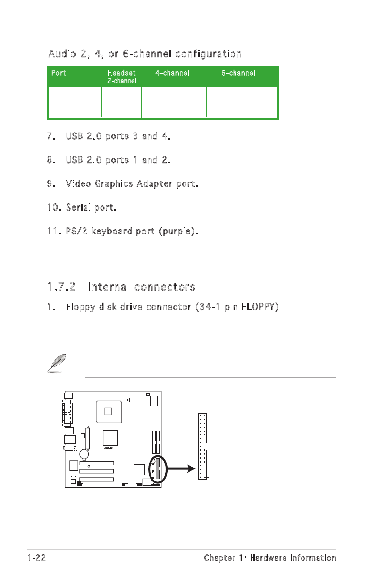
Aud i o 2 , 4 , o r 6- c han nel con fig u rat ion
P5VDC-TVM Floppy Disk Drive Connector
P5VDC-TVM
®
NOTE: Orient the red markings on
the floppy ribbon cable to PIN 1.
PIN 1
FLOPPY
Por t H e a dset 4-ch a n n el 6 -cha n n e l
2-channel
Light Blue Line In Rear Speaker Out Rear Speaker Out
Lime Line Out Front Speaker Out Front Speaker Out
Pink Mic In Mic In Center/Subwoofer
7. U S B 2.0 p o r ts 3 a n d 4. These two 4-pin Universal Serial Bus (USB)
ports are available for connecting USB 2.0 devices.
8. U S B 2.0 p o r ts 1 a n d 2. These two 4-pin Universal Serial Bus
(USB) ports are available for connecting USB 2.0 devices.
9. V i d e o Gr a p h ics A d a pter p o rt. This 15-pin port is for a VGA
monitor or other VGA-compatible devices.
10. S e r ial p o r t. This 9-pin COM1 port is for pointing devices or other
serial devices.
11. P S / 2 ke y b o ard p o r t (p u r p le). This port is for a PS/2 keyboard.
1.7 .2 Int er na l c on ne cto rs
1. F l o p py d i s k dri v e con n e c t or ( 3 4 - 1 pi n F LOPP Y )
This connector is for the provided oppy disk drive (FDD) signal cable.
Insert one end of the cable to this connector, then connect the other
end to the signal connector at the back of the oppy disk drive.
Pin 5 on the connector is removed to prevent incorrect cable connection
when using a FDD cable with a covered Pin 5.
1-22 Chapter 1: Hardware information
Page 31

2. I D E conn e c t ors ( 4 0 -1 p i n PRI_ I D E , SE C _ I DE)
P5VDC-TVM IDE Connectors
P5VDC-TVM
®
PRI_IDE
SEC_IDE
NOTE: Orient the red markings
(usually zigzag) on the ID
ribbon cable to PIN 1.
PIN 1
These connectors are for Ultra DMA 133/100/66 signal cables.
The Ultra DMA 133/100/66 signal cable has three connectors: a
blue connector for the primary IDE connector on the motherboard,
a black connector for an Ultra DMA 133/100/66 IDE slave device
(optical drive/hard disk drive), and a gray connector for an Ultra
DMA 133/100/66 IDE master device (hard disk drive). If you install
two hard disk drives, you must congure the second drive as a slave
device by setting its jumper accordingly. Refer to the hard disk
documentation for the jumper settings.
• Pin 20 on the IDE connector is removed to match the covered hole
on the Ultra DMA cable connector. This prevents incorrect insertion
when you connect the IDE cable.
• Use the 80-conductor IDE cable for Ultra DMA 133/100/66 IDE
devices.
1-23ASUS P5VDC-TVM
Page 32

3. S e r i al A T A conn e c t ors
P5VDC-TVM SATA Connectors
SATA2
GND
RSATA_TXP2
RSATA_TXN2
GND
RSATA_RXP2
RSATA_RXN2
GND
GND
RSATA_TXP1
RSATA_TXN1
GND
RSATA_RXP1
RSATA_RXN1
GND
P5VDC-TVM
®
SATA1
(7-p i n SATA 1 [ blac k ] , SAT A 2 [bla c k ] )
These connectors are for the Serial ATA signal cables for Serial ATA
hard disk drives.
Important notes on Serial ATA
• Install the Windows® 2000 Service Pack 4 or the Windows® XP
Service Pack1 before using Serial ATA.
• Plug your Serial ATA boot disk on the master port (SATA1 and
SATA2) to support S3 function. Refer to the table below for details.
Ser i al ATA Ma s ter / Sl a ve c on n ect o rs
Con n e c tor Col o r S e t t ing Use
SATA1 Black Master Boot Disk
SATA2 Black Slave Data Disk
1-24 Chapter 1: Hardware information
Page 33

4. C P U and C h a ssis F a n co n n e ctor s
P5VDC-TVM FAN Connectors
P5VDC-TVM
®
CPU_FAN
GND
CPU FAN PWR
CPU FAN IN
CPU FAN PWM
CHA_FAN
GND
Rotation
+12V
(4-p i n CPU_ F A N , 3- p i n CHA _ F A N )
The fan connectors support cooling fans of 350mA~740mA (8.88W
max.) or a total of 1A~2.22A (26.64W max.) at +12V. Connect the
fan cables to the fan connectors on the motherboard, making sure
that the black wire of each cable matches the ground pin of the
connector.
Do not forget to connect the fan cables to the fan connectors.
Insufcient air ow inside the system may damage the motherboard
components. These are not jumpers! Do not place jumper caps on the
fan connectors!
1-25ASUS P5VDC-TVM
Page 34

5. U S B conn e c t ors ( 1 0 -1 p i n USB5 6 , USB7 8 )
P5VDC-TVM USB 2.0 Connectors
P5VDC-TVM
®
USB56
USB+5V
USB_P6-
USB_P6+
GND
NC
USB+5V
USB_P5-
USB_P5+
GND
1
USB78
USB+5V
USB_P10-
USB_P10
GND
NC
USB+5V
USB_P9-
USB_P9+
GND
1
These connectors are for USB 2.0 ports. Connect the USB/GAME
module cable to any of these connectors, then install the module to a
slot opening at the back of the system chassis. These USB connectors
comply with USB 2.0 specication that supports up to 480 Mbps
connection speed.
Never connect a 1394 cable to the USB connectors. Doing so will
damage the motherboard!
The USB module is purchased separately.
1-26 Chapter 1: Hardware information
Page 35

6. A T X powe r c onne c t o rs ( 2 0 - pin A T X PWR, 4 - pin A T X 12V)
P5VDC-TVM ATX Power Connectors
P5VDC-TVM
®
ATX12V
+12V DC
GND
+12V DC
GND
ATXPWR
+3.3VDC
-12.0VDC
GND
PS_ON#
GND
GND
GND
-5.0VDC
+5.0VDC
+5.0VDC
PWR_OK
+12.0VDC
+3.3VDC
+3.3VDC
GND
+5.0VDC
GND
+5.0VDC
GND
+5VSB
These connectors are for ATX power supply plugs. The plugs from
the power supply are designed to t these connectors in only one
orientation. Find the proper orientation and push down rmly until the
connectors completely t.
•
You can also use a Power Supply Unit (PSU) with a 24-pin ATX power
connector on this motherboard.
•
Do not forget to connect the 4-pin ATX +12 V power plug;
otherwise, the system will not boot up.
• Use a PSU with a minimum power rating of 300 W on this
motherboard. We recommend that you use a PSU with a
higher power output when conguring a system with more
power-consuming devices. The system may become unstable or may
not boot up if the power is inadequate.
1-27ASUS P5VDC-TVM
Page 36

7. F r o n t pa n e l aud i o conn e c t or ( 1 0 - 1 pi n F P_AU D I O )
P5VDC-TVM Front Panel Audio Connector
P5VDC-TVM
®
BLINE_OUT_L
MIC2
Line out_R
Line out_L
BLINE_OUT_R
NC
MICPWR
+5VA
AGND
FP_AUDIO
P5VDC-TVM COM Port Connector
P5VDC-TVM
®
COM2
PIN1
This connector is for a chassis-mounted front panel audio I/O module
that supports legacy AC ‘97 audio standard. Connect one end of the
front panel audio I/O module cable to this connector.
8. S e r i al p o r t con n e c tor ( 1 0 -1 p i n COM2 )
This connector is for a serial (COM) port. Connect the serial port
module cable to this connector, then install the module to a slot
opening at the back of the system chassis.
Serial port module is purchased separately.
1-28 Chapter 1: Hardware information
Page 37

9. I n t e rnal a u dio c o nnec t o r s (4 - p i n CD , A U X)
P5VDC-TVM Internal Audio Connectors
P5VDC-TVM
®
AUX
(white)
CD
(black)
Right Audio Channel
Left Audio Channel
Ground
Ground
Right Audio Channel
Left Audio Channel
Ground
Ground
P5VDC-TVM Digital Audio Connector
P5VDC-TVM
®
+5V
SPDIFOUT
GND
SPDIF_OUT
These connectors allow you to receive stereo audio input from sound
sources such as a CD-ROM, TV tuner, or MPEG card.
10. D i g ital a u dio c o n nect o r (4-1 p i n SP D I F _OUT )
This connector is for additional Sony/Philips Digital Interface (S/PDIF)
port(s). Connect the S/PDIF module cable to this connector, then
install the module to a slot opening at the back of the system chassis.
The S/PDIF module is purchased separately.
1-29ASUS P5VDC-TVM
Page 38
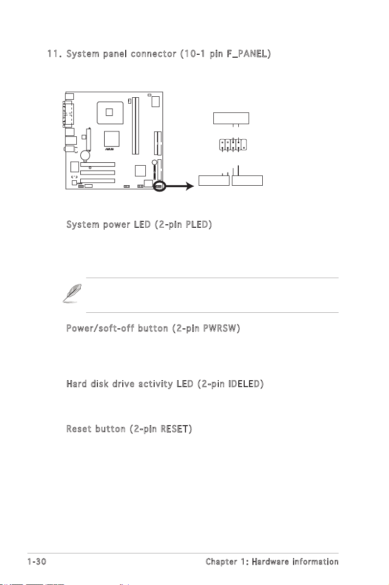
11. S y s tem p a n el c o n n ecto r ( 10-1 p i n F_ P A N EL)
P5VDC-TVM System Panel Connector
P5VDC-TVM
®
F_PANEL
PWRGround
GNDReset
IDE_LED+
IDE_LED-
RESETIDE LED
PWRSW
This connector supports several chassis-mounted functions.
•
Syst e m powe r L ED ( 2 - p in P L E D )
This 2-pin connector is for the system power LED. Connect the
chassis power LED cable to this connector. The system power LED
lights up when you turn on the system power, and blinks when the
system is in sleep mode.
Power LED may remain blinking after AC Power loss or when AC Power
cord is plugged in the rst time. Only if turing on-off system normally
one more time.Power Led will not blink afterwards.
•
Powe r / s oft- o f f but t o n (2- p i n PWR S W )
This connector is for the system power button. Pressing the power
button turns the system ON or puts the system in SLEEP or SOFT-OFF
mode depending on the BIOS settings. Pressing the power switch for
more than four seconds while the system is ON turns the system OFF.
•
Hard d i sk d r i v e ac t i v ity L E D (2- p i n IDE L E D )
This 2-pin connector is for the HDD Activity LED. Connect the HDD
Activity LED cable to this connector. The IDE LED lights up or ashes
when data is read from or written to the HDD.
•
Rese t b utto n ( 2-pi n R ESET )
This 2-pin connector is for the chassis-mounted reset button for
system reboot without turning off the system power.
1-30 Chapter 1: Hardware information
Page 39

This chapter tells how to change
the system settings through the BIOS
Setup menus. Detailed descriptions
of the BIOS parameters are also
provided.
BIOS setup
2
Page 40

2.1 BIOS setup program
This motherboard supports a programmable rmware chip that you can
update using the provided utility.
Use the BIOS Setup program when you are installing a motherboard,
reconguring your system, or prompted to “Run Setup.” This section
explains how to congure your system using this utility.
Even if you are not prompted to use the Setup program, you can change
the conguration of your computer in the future. For example, you can
enable the security password feature or change the power management
settings. This requires you to recongure your system using the BIOS Setup
program so that the computer can recognize these changes and record
them in the CMOS RAM of the rmware hub.
The rmware hub on the motherboard stores the Setup utility. When you
start up the computer, the system provides you with the opportunity to
run this program. Press <Del> during the Power-On Self-Test (POST) to
enter the Setup utility; otherwise, POST continues with its test routines.
If you wish to enter Setup after POST, restart the system by pressing
<Ctrl> + <Alt> + <Del>, or by pressing the reset button on the system
chassis. You can also restart by turning the system off and then back on.
Do this last option only if the rst two failed.
The Setup program is designed to make it as easy to use as possible. Being
a menu-driven program, it lets you scroll through the various sub-menus
and make your selections from the available options using the navigation
keys.
• The default BIOS settings for this motherboard apply for most
conditions to ensure optimum performance. If the system becomes
unstable after changing any BIOS settings, load the default settings
to ensure system compatibility and stability. Select the Load
Optimized Defaults from the BIOS menu screen. See section “2.2
BIOS menu screen.”
• The BIOS setup screens shown in this section are for reference
purposes only, and may not exactly match what you see on your
screen.
• Visit the system builder’s website to download the latest BIOS le
for this motherboard.
2-2 Chapter 2: BIOS setup
Page 41

2.2 BIOS menu screen
When you enter the BIOS, the following screen appears. The BIOS menu
screen displays the items that allow you to make changes to the system
conguration. To access the menu items, press the up/down/right/left
arrow key on the keyboard until the desired item is highlighted, then press
[Enter] to open the specic menu.
Phoenix - Award BIOS CMOS Setup Utility
Standard BIOS Features
Advanced BIOS Features
Integrated Peripherals
Power Management Setup
PC Health Status
Load Optimized Defaults
Set Supervisor Password
Esc : Quit : Select Item
F9: Optimized Defaults F10 : Save & Exit Setup
Time, Date, Hard Disk Type...
Leg e n d box
Lis t b ox
Set User Password
Save & Exit Setup
Exit Without Saving
Leg e nd box
The keys in the legend bar allow you to navigate through the various setup
menus.
Nav i g a tion K e y (s) Fun c t i on De s c r iptio n
<F1> Displays the General Help screen from anywhere in
<Esc> Returns to the main menu from a sub-menu or
Left or Right arrow Selects the menu item to the left or right
Up or Down arrow Moves the highlight up or down between elds
<Enter> Brings up a selection menu for the highlighted
<+> or <PgUp> Moves the cursor to the rst eld
<-> or <PgDn> Moves the cursor to the last eld
<F5> Loads the previous values
<F6> Loads the fail-safe defaults
<F9> Loads the optimized defaults
<F10> Saves changes and exits Setup
the BIOS Setup
prompts you to quit the setup program
eld
ASUS P5VDC-TVM 2-3
Page 42
Lis t b o x
This box appears only in the opening screen. The box displays an initial list
of congurable items in the menu you selected.
Sub - me n u
Note that a right pointer symbol ( ) appears to the left of certain elds.
This pointer indicates that you can display a sub-menu from this eld. A
sub-menu contains additional options for a eld parameter. To display a
sub-menu, move the highlight to the eld and press <Enter>. The sub-menu
appears. Use the legend keys to enter values and move from eld to eld
within a sub-menu as you would within a menu. Use the <Esc> key to
return to the main menu.
Take some time to familiarize yourself with the legend keys and their
corresponding functions. Practice navigating through the various menus
and sub-menus. If you accidentally make unwanted changes to any of
the elds, press <F6> to load the fail-safe default values. While moving
around through the Setup program, note that explanations appear in the
Item Specic Help window located to the right of each menu. This window
displays the help text for the currently highlighted eld.
2-4 Chapter 2: BIOS setup
Page 43

2.3 Standard BIOS Features
The Standard BIOS Features screen gives you an overview of the basic
system information.
Phoenix - Award BIOS CMOS Setup Utility
Standard BIOS Features
Date (mm:dd:yy) Mon, Jan 24 2005
Time (hh:mm:ss) 11 : 35 : 24
IDE Channel 0 Master [ST320410A]
IDE Channel 0 Slave [ASUS CD-S520/A]
IDE Channel 1 Master [None]
IDE Channel 1 Slave [None]
SATA Channel 2 Master [None]
SATA Channel 3 Master [None]
Drive A [1.44M, 3.5 in.]
Halt On [All, But Keyboard]
Base Memory 640K
Extended Memory 252928K
Total Memory 253952K
: Move Enter:Select +/-/PU/PD:Value F10:Save&Exit ESC:Exit F1:General Help
F5: Previous Values F6: Fail-Safe Defaults F9: Optimized Defaults
Dat e [ D ay, xx / xx/ x xx x ]
Allows you to set the system date.
Tim e [ x x:x x :x x ]
Allows you to set the system time.
IDE Ch a nne l 0 Mas t er / Sla v e
IDE Ch a nne l 1 Mas t er / Sla v e
While entering Setup, the BIOS automatically detects the presence of IDE
devices. There is a separate sub-menu for each IDE device. Select a device
item then press <Enter> to display the IDE device information.
Select Menu
Item Specic Help
Change the day, month,
year and century
Phoenix - Award BIOS CMOS Setup Utility
IDE HDD Auto-Detection [Press Enter]
IDE Channel 0 Master [Auto]
Access Mode [Auto]
Capacity 20021 MB
Cylinder 38792
Head 16
Precomp 0
Landing Zone 38791
Sector 63
: Move Enter:Select +/-/PU/PD:Value F10:Save&Exit ESC:Exit F1:General Help
F5: Previous Values F6: Fail-Safe Defaults F9: Optimized Defaults
IDE Channel 0 Master
Select Menu
Item Specic Help
To auto-detect the HDD’s
size, head... on this
channel
ASUS P5VDC-TVM 2-5
Page 44

IDE HDD Auto-Detection [Press Enter]
Allows auto-detection of the hard disk drive’s specications.
IDE Channel 0, 1 Master/Slave [Auto]
Sets the selected channel as Master or Slave.
Conguration options: [None] [Auto] [Manual]
Access Mode [Auto]
This item allows the user to select the sector addressing mode. CHS
mode supports 528 MB hard disks. LBA (logical block addressing)
mode supports hard disks up to 128 GB in size. Large mode (also
called extended CHS mode) supports hard disks above 528 MB in size,
but does not support LBA mode. Conguration options: [CHS] [LBA]
[Large] [Auto]
Before attempting to congure a hard disk drive, make sure you
have the correct conguration information supplied by the drive
manufacturer. Incorrect settings may cause the system to fail to
recognize the installed hard disk.
Capacity
Displays the auto-detected hard disk capacity. This item is not
congurable.
Cylinder
Shows the number of the hard disk cylinders. This item is not
congurable.
Head
Shows the number of the hard disk read/write heads. This item is not
congurable.
Precomp
Shows the number of precomp per track. This item is not congurable.
Landing Zone
Shows the number of landing zone per track. This item is not
congurable.
Sector
Shows the number of sectors per track. This item is not congurable.
After entering the IDE hard disk drive information into the BIOS, use a
disk utility, such as FDISK, to partition and format new IDE hard disk
drives. This is necessary so that you can write or read data from the
hard disk. Make sure to set the partition of the Primary IDE hard disk
drives to active.
2-6 Chapter 2: BIOS setup
Page 45

SAT A C h ann e l 2 , 3 Mas ter
While entering Setup, the BIOS automatically detects the presence of Serial
ATA devices. There is a separate sub-menu for each SATA device. Select a
device item then press <Enter> to display the SATA device information.
Phoenix - Award BIOS CMOS Setup Utility
SATA Channel 2 Master
IDE Auto-Detection [Press Enter]
Extended IDE Drive [Auto]
Access Mode [Auto]
Capacity 20021 MB
Cylinder 38792
Head 16
Precomp 0
Landing Zone 38791
Sector 63
: Move Enter:Select +/-/PU/PD:Value F10:Save&Exit ESC:Exit F1:General Help
F5: Previous Values F6: Fail-Safe Defaults F9: Optimized Defaults
Extended IDE Drive [Auto]
Select [Auto] to automatically detect a SATA hard disk drive. If
automatic detection is successful, Setup program automatically lls
in the correct values for the remaining elds (including Capacity,
Cylinder, Head, Precomp, Landing Zone, Sector) on this sub-menu.
Conguration options: [None] [Auto]
Access Mode [Auto]
Allows the user to select the sector addressing mode. Conguration
options: [Large] [Auto]
Select Menu
Item Specic Help
To auto-detect the HDD’s
size, head... on this
channel
Before attempting to congure a hard disk drive, make sure you
have the correct conguration information supplied by the drive
manufacturer. Incorrect settings may cause the system to fail to
recognize the installed hard disk.
Capacity
Displays the auto-detected hard disk capacity. This item is not
congurable.
Cylinder
Shows the number of the hard disk cylinders. This item is not
congurable.
ASUS P5VDC-TVM 2-7
Page 46

Head
Shows the number of the hard disk read/write heads. This item is not
congurable.
Precomp
Shows the number of precomp per track. This item is not congurable.
Landing Zone
Shows the number of landing zone per track. This item is not
congurable.
Sector
Shows the number of sectors per track. This item is not congurable.
After entering the IDE hard disk drive information into the BIOS, use a
disk utility, such as FDISK, to partition and format new IDE hard disk
drives. This is necessary so that you can write or read data from the
hard disk. Make sure to set the partition of the Primary IDE hard disk
drives to active.
Dri v e A [1 . 44M , 3 . 5 i n .]
Species the capacity and physical size of diskette drive A. Do not select
[None] if you are using a oppy disk drive. Conguration options: [None]
[1.2M , 5.25 in.] [720K , 3.5 in.] [1.44M, 3.5 in.]
Hal t O n [A l l , Bu t K eybo a r d ]
Sets the system to halt on errors according to the system functions
specied in each option. Conguration options: [All Errors] [No Errors]
[All, But Keyboard] [All, But Diskette] [All, But Disk/Key]
2-8 Chapter 2: BIOS setup
Page 47
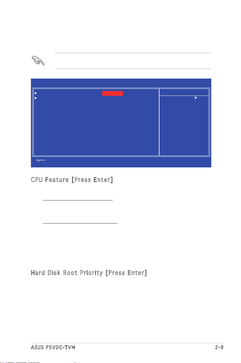
2.4 Advanced BIOS Features
The Advanced BIOS Features menu items allow you to change the advanced
BIOS settings.
Take caution when changing the settings of the Advanced BIOS Features
items. Incorrect eld values may cause the system to malfunction.
Phoenix - Award BIOS CMOS Setup Utility
Advanced BIOS Features
CPU Feature [Press Enter]
Hard Disk Boot Priority [Press Enter]
First Boot Device [Hard Disk]
Second Boot Device [CDROM]
Third Boot Device [Floppy]
Fourth Boot Device [LS120]
Boot Up Floppy Seek [Disabled]
Boot Up Num-Lock Status [On]
Virus Warning [Disabled]
Security Option [Setup]
HDD S.M.A.R.T. Capability [Disabled]
Full Screen LOGO Show [Disabled]
: Move Enter:Select +/-/PU/PD:Value F10:Save&Exit ESC:Exit F1:General Help
F5: Previous Values F6: Fail-Safe Defaults F9: Optimized Defaults
CPU Fe a tur e [ P res s E n ter ]
Allows you to view the CPU feature setup menu.
Execute Disable Bit [Enabled]
When disabled, the processor forces the XD feature ag to always
return 0. Conguration options: [Disabled] [Enabled]
CPU Hyper-Threading [Enabled]
Enables or disabled the processor Hyper-Threading technology.
Set this item to [Enabled] if you are using Windows® XP, Linux 2.4,
or other operating systems optimized for Intel® Hyper-Threading
technology. Set this item to [Disabled] if you are using other
operating systems that are not optimized for Intel® Hyper-Threading
technology. Conguration options: [Disabled] [Enabled]
Select Menu
Item Specic Help
CPU feature setup menu
Har d D i sk B oo t Pr i or i ty [ Pr e ss E nt e r]
Allows you to select the hard disk boot device priority. The number of
devices that appears on the screen depends on the number of devices
installed in the system.
ASUS P5VDC-TVM 2-9
Page 48

Fir s t/ S eco n d/ T hir d /F o urt h B o ot D ev i ce
Allows you to assign the boot device priority. Conguration options:
[Floppy] [LS120] [Hard Disk] [CDROM] [ZIP] [USB-FDD] [USB-ZIP]
[USB-CDROM] [LAN] [Disabled]
Boo t U p Fl o pp y Se e k [ Dis a bl e d]
When [Enabled], the BIOS will seek the opy disk drive to determine
whether the drive has 40 or 80 tracks.
Conguration options: [Disabled] [Enabled]
Boo t U p Nu m -L o ck S ta t us [ On ]
Allows you to select the power-on state for the NumLock.
Conguration options: [Off] [On]
Vir u s W arn i ng [Di s ab l ed]
When [Enabled], the BIOS will seek the opy disk drive to determine
whether the drive has 40 or 80 tracks.
Conguration options: [Disabled] [Enabled]
Sec u ri t y O p ti o n [ S et u p]
Select [Setup] to require the password before entering the BIOS Setup.
Select [System] to require the password before entering the system.
Conguration options: [Setup] [System]
HDD S. M .A. R .T . Ca p ab i lit y [ D isa b le d ]
Enables or disables Hard Disk SMART capability support.
Conguration options: [Disabled] [Enabled]
Ful l S c ree n L O GO S ho w [D i sa b led ]
Allows you to enable or disable the full screen logo display feature.
Conguration options: [Disabled] [Enabled]
2-10 Chapter 2: BIOS setup
Page 49

2.5 Integrated Peripherals
The Integrated Peripherals menu items allow you to change the onboard
devices conguration settings.
Phoenix - Award BIOS CMOS Setup Utility
Integrated Peripherals
Onchip IDE Device [Press Enter]
Onboard Device [Press Enter]
SuperIO Device [Press Enter]
: Move Enter:Select +/-/PU/PD:Value F10:Save&Exit ESC:Exit F1:General Help
F5: Previous Values F6: Fail-Safe Defaults F9: Optimized Defaults
Onc h ip IDE De v ice
This sub-menu contains IDE function-related items. Select an item then
press <Enter> to edit.
Phoenix - Award BIOS CMOS Setup Utility
IDE Primary Master PIO [Auto]
IDE Primary Slave PIO [Auto]
IDE Secondary Master PIO [Auto]
IDE Secondary Slave PIO [Auto]
IDE Primary Master UDMA [Auto]
IDE Primary Slave UDMA [Auto]
IDE Secondary Master UDMA [Auto]
IDE Secondary Slave UDMA [Auto]
On-Chip Serial ATA [Enabled]
SATA Mode [IDE]
: Move Enter:Select +/-/PU/PD:Value F10:Save&Exit ESC:Exit F1:General Help
F5: Previous Values F6: Fail-Safe Defaults F9: Optimized Defaults
Onchip IDE Device
Select Menu
Item Specic Help
Onchip IDE Device setup
menu
Select Menu
Item Specic Help
Set a PIO mode for
the IDE device.
Mode 0/through 4
successive increase in
performance.
ASUS P5VDC-TVM 2-11
Page 50

IDE Pr i mar y , S eco n da r y M a st e r/S l av e PI O [ A uto ]
This option lets you set a PIO (Programmed Input/Output) mode for the
IDE device. Modes 0 through 4 provide successive increase in performance.
Conguration options: [Auto] [Mode 0] [Mode 1] [Mode 2] [Mode 3] [Mode 4]
IDE Pr i mar y , S eco n da r y M a st e r/S l av e UD M A [ Aut o ]
Ultra DMA capability allows improved transfer speeds and data integrity for
compatible IDE devices. Set to [Disabled] to suppress Ultra DMA capability.
Conguration options: [Disabled] [Auto]
On- C hi p Se r ia l AT A [ E nab l ed ]
Conguration options: [Disabled] [Enabled]
SAT A M o de [ ID E ]
Conguration options: [IDE] [RAID]
2-12 Chapter 2: BIOS setup
Page 51

Onb o ar d De v ic e
This sub-menu allows you to set the congurations for onboard devices.
Select an item then press <Enter> to edit.
Phoenix - Award BIOS CMOS Setup Utility
USB Controller [Enabled]
USB 2.0 Controller [Enabled]
USB Keyboard Support [Enabled]
Onboard AC97 Audio [Enabled]
Onboard LAN Device [Enabled]
Onboard LAN Boot ROM [Disabled]
: Move Enter:Select +/-/PU/PD:Value F10:Save&Exit ESC:Exit F1:General Help
F5: Previous Values F6: Fail-Safe Defaults F9: Optimized Defaults
Onboard Device
Select Menu
Item Specic Help
Enable/Disable Onboard
1394 device support.
USB Co n tro l le r [E n ab l ed]
Allows you to enable or disable the USB 2.0 controller.
Conguration options: [Enabled] [Disabled]
USB 2.0 Co n tro lle r [E nab l ed]
Allows you to enable or disable the EHCI controller. If the BIOS has built-in
high speed USB support, this item will be enabled automatically when a high
speed device is attached. Conguration options: [Enabled] [Disabled]
USB Ke y boa r d S upp o rt [En a bl e d]
Allows you to enable or disable legacy USB device support.
Conguration options: [Disabled] [Enabled]
AC9 7 Au dio [Au to]
Allows the BIOS to automatically enable support for legacy AC`97 audio, or
disable the onboard AC`97 Audio controller.
Conguration options: [Enabled] [Disabled]
Onb o ar d LA N D e vic e [ E nab l ed ]
Allows you to enable or disable the onboard LAN device support.
Conguration options: [Disabled] [Enabled]
Onb o ar d LA N B o ot R OM [Di s ab l ed]
Allows you to enable or disable the boot ROM of the onboard LAN chip.
Conguration options: [Enabled] [Disabled]
ASUS P5VDC-TVM 2-13
Page 52

Sup e rI O De v ic e
This sub-menu allows you to set the congurations for SuperIO devices.
Select an item then press <Enter> to edit.
Phoenix - Award BIOS CMOS Setup Utility
Onboard Serial Port 1 [3F8/IRQ4]
Onboard Serial POrt 2 [2F8/IRQ3]
Onboard Parallel Port [378/IRQ7]
Parallel Port Mode [ECP]
ECP Mode Use DMA [3]
: Move Enter:Select +/-/PU/PD:Value F10:Save&Exit ESC:Exit F1:General Help
F5: Previous Values F6: Fail-Safe Defaults F9: Optimized Defaults
SuperIO Device
Select Menu
Item Specic Help
S e l e c t S e r i a l P o r t 1
base address.
Onb o ar d Se r ia l Po r t 1 [3 F 8/I RQ4 ]
A l l o w s y o u t o s e t t h e S e r i a l P o r t 1 b a s e a d d r e s s .
Conguration options: [Disabled] [3F8/IRQ4] [2F8/IRQ3] [3E8/IRQ4] [2E8/
IRQ3] [Auto]
Onb o ar d Se r ia l Po r t 2 [2 F 8/I RQ3 ]
A l l o w s y o u t o s e t t h e S e r i a l P o r t 2 b a s e a d d r e s s .
Conguration options: [Disabled] [3F8/IRQ4] [2F8/IRQ3] [3E8/IRQ4] [2E8/
IRQ3] [Auto]
Onb o ar d Pa r al l el P or t [3 7 8/I RQ7 ]
Allows you to set the base address of the onboard parallel port connector.
Conguration options: [Disabled] [378/IRQ7] [278/IRQ5] [3BC/IRQ7]
Onb o ar d Se r ia l Po r t 1 [3 F 8/I RQ4 ]
Allows you to set the Serial Port 1 base address.
Conguration options: [Disabled] [3F8/IRQ4] [2F8/IRQ3] [3E8/IRQ4]
[2E8/IRQ3] [Auto]
Onb o ar d Se r ia l Po r t 2 [2 F 8/I RQ3 ]
Allows you to set the Serial Port 2 base address.
Conguration options: [Disabled] [3F8/IRQ4] [2F8/IRQ3] [3E8/IRQ4]
[2E8/IRQ3] [Auto]
2-14 Chapter 2: BIOS setup
Page 53

2.6 Power Management Setup
The Power Management Setup menu items allow you to change the
settings for the Advanced Power Management (APM) and Advanced
Conguration and Power Interface (ACPI).
Phoenix - Award BIOS CMOS Setup Utility
Power Management Setup
ACPI Function [Enabled]
ACPI Suspend Type [S3(STR)]
Off by Power Button [Instant-Off]
Resume by PCI PME [Disabled]
Resume by Ring [Disabled]
Resume by USB (S3) [Enabled]
Resume by Alarm [Disabled]
x Date (of Month) Alarm 0
x Time (hh:mm:ss) Alarm 0 : 0 : 0
State after Power Failure [Off]
: Move Enter:Select +/-/PU/PD:Value F10:Save&Exit ESC:Exit F1:General Help
F5: Previous Values F6: Fail-Safe Defaults F9: Optimized Defaults
ACP I F u nct i on [En a bl e d]
Allows you to enable or disable the ACPI support for the operating system.
Conguration options: [Enabled] [Disabled]
ACP I S u spe n d T ype [S 1 (PO S )]
Allows you to select the ACPI state used for system suspend.
Conguration options: [S1(POS)] [S3(STR)]
Select Menu
Item Specic Help
Enable/Disable ACPI
support for operating
system.
Off by Pow e r B utt o n [ Ins t an t -Of f ]
When set to [Instant-Off], the system goes to soft-off when you press
the power button for less than 4 seconds. When set to [Delay 4 Sec],
press the power button for more than 4 seconds to power off the system.
Conguration options: [Instant-Off] [Delay 4 Sec]
Res u me by P CI PME [E n abl e d]
Enables or disables system wake-up by power management event (PME).
Conguration options: [Disabled] [Enabled]
ASUS P5VDC-TVM 2-15
Page 54

Res u me by R in g [E n ab l ed]
Allows you to enable or disable system power up when the external modem
receives a call while the computer is in soft-off mode.
Conguration options: [Disabled] [Enabled]
The computer cannot receive or transmit data until the computer and
applications are fully running. Thus, connection cannot be made on the
rst try. Turning an external modem off and then back on while the
computer is off causes an initialization string that turns the system
power on.
Res u me by U SB (S3 ) [E nab l ed]
Allows you to wake up the system using a USB mouse or keyboard.
Conguration options: [Disabled] [Enabled]
Res u me by A la r m [ D is a ble d ]
Allows you to enable or disable RTC to generate an event. When this item
is enabled, you can set the date and time of alarm using the two following
items. Conguration options: [Disabled] [Enabled]
The following items become congurable only when the Resume by
Alarm item is set to [Enabled].
Day of Mon t h A lar m [ N A]
To set the day of alarm, highlight this item and press <Enter> to display
a pop-up menu. Key in a value (Min=0, Max=31), then press <Enter>.
Selecting [0] means the alarm will set off everyday.
Tim e ( h h:m m :s s ) A l ar m [0 : 0 : 0 ]
To set the time of alarm:
1. Highlight this item and press <Enter> to display a pop-up menu for the
hour eld.
2. Key-in a value (Min=0, Max=23), then press <Enter>.
3. Press tab to move to the minutes eld, then press <Enter>.
4. Key-in a minute value (Min=0, Max=59), then press <Enter>.
5. Press tab to move to the seconds eld, then press <Enter>.
6. Key-in a value (Min=0, Max=59), then press <Enter>.
Sta t e a fte r P o wer Fa i lur e [ O ff]
When set to Off, the system goes into off state after an AC power loss.
When set to On, the system turns on after an AC power loss. When set to
Former-Sts, the system goes to its previous state before the AC power
loss. Conguration options: [Off] [On] [Former-Sts]
2-16 Chapter 2: BIOS setup
Page 55

2.7 PC Health Status
The PC Health Status screen shows the motherboard CPU and fan
temperatures, and allows you to set threshold levels for efcient system
operation.
Phoenix - Award BIOS CMOS Setup Utility
CPU Temperature 38oC
MB Temperature 37oC
CPU Fan Speed 3835 RPM
System Fan Speed 0 RPM
VCORE Voltage 1.50 V
3.3 V voltage 3.34 V
+5V in 5.19 V
+13V in 11.61 V
CPU FAN SPEED CONTROL [Enabled]
Start Up Temperature(ºC) [50]
Full Speed Temperature(ºC) [70]
Start Up PWM [60]
Slope Select PWM/ºC [4 PWM/ºC]
: Move Enter:Select +/-/PU/PD:Value F10:Save&Exit ESC:Exit F1:General Help
F5: Previous Values F6: Fail-Safe Defaults F9: Optimized Defaults
PC Health Status
Select Menu
Item Specic Help
Press <Enter> to enable
or disable.
The BIOS auto-detects the former eight items. The user cannot
congure these items.
CPU Te m per a tu r e [ x xx º C]
MB T em p era t ur e [x x xº C ]
The onboard hardware monitor automatically detects and displays the CPU
and motherboard temperatures.
CPU Fa n Sp e ed [xx x xR P M]
Sys t em Fan Sp e ed [ xx x xRP M ]
The onboard hardware monitor automatically detects and displays the
CPU and system fan speed in rotations per minute (RPM). If the fan is not
connected to the motherboard, the eld shows 0 RPM.
VCO R E V olt a ge , 3. 3 V V olt a ge, +5 V in , + 1 2V i n
The onboard hardware monitor automatically detects the voltage output
through the onboard voltage regulators.
CPU Fa n Sp e ed Con t ro l [E n ab l ed]
Allows you to enable or disable the CPU fan speed controller.
Conguration options: [Enabled] [Disabled]
ASUS P5VDC-TVM 2-17
Page 56

Sta r t U p T e mp e rat u re (ºC ) [ 5 0]
Allows you to set the fan start-up temperature.
Conguration options: [0] [1] ~ [100]
Ful l S p eed Te m per a tu r e ( º C) [70 ]
Allows you to set the threshold temperature before the fan begins running
at full speed. Conguration options: [0] [1] ~ [100]
Sta r t U p P W M [ 60]
Sets the start-up Pulse Width Modulation (PWM) value when the fan starts
running. Conguration options: [0] [1] ~ [127]
Slo p e S ele c t P WM/ º C [ 4 P W M/ º C]
Sets the PWM increase value per degree Celcius to control the fan speed
when the system temperature increases.
Conguration options: [0 PWM/ºC] [1 PWM/ºC] [2 PWM/ºC] [4 PWM/ºC]
[8 PWM/ºC] [16 PWM/ºC] [32 PWM/ºC] [64 PWM/ºC]
2.8 Other items
2.8 .1 Loa d Op tim iz ed De fa ul ts
Allows you to load the optimized defaults.
2.8 .2 Set S up erv is or Pa ss wo rd
Allows you to set the supervisor password. To set a password, press
<Enter>. Type in and conrm the password when prompted.
2.8 .3 Set U se r P as sw ord
Allows you to set a user password for access to system after boot-up.
2.8 .4 Sav e & Exi t Se tup
Once you are nished making your selections, choose this option to ensure
that the values you selected are saved to the CMOS RAM. When you select
this option, a conrmation window appears. Select Yes to save changes and
exit.
2.8 .5 Exi t Wi tho ut S avi ng
Select this option only if you do not want to save the changes that you
made to the Setup program.
2-18 Chapter 2: BIOS setup
 Loading...