


WS C246M PRO
Motherboard

E14689
Revised Edition V2
August 2018
Copyright© 2018 ASUSTeK COMPUTER INC. All Rights Reserved.
No part of this manual, including the products and software described in it, may be reproduced, transmitted, transcribed, stored in a retrieval system, or translated into any language in any form or by any means, except documentation kept by the purchaser for backup purposes, without the express written permission of ASUSTeK COMPUTER INC. (“ASUS”).
Product warranty or service will not be extended if: (1) the product is repaired, modified or altered, unless such repair, modification of alteration is authorized in writing by ASUS; or (2) the serial number of the product is defaced or missing.
ASUS PROVIDES THIS MANUAL “AS IS” WITHOUT WARRANTY OF ANY KIND, EITHER EXPRESS OR IMPLIED, INCLUDING BUT NOT LIMITED TO THE IMPLIED WARRANTIES OR CONDITIONS OF MERCHANTABILITY OR FITNESS FOR A PARTICULAR PURPOSE. IN NO EVENT SHALL ASUS, ITS DIRECTORS, OFFICERS, EMPLOYEES OR AGENTS BE LIABLE FOR ANY INDIRECT, SPECIAL, INCIDENTAL, OR CONSEQUENTIAL DAMAGES (INCLUDING DAMAGES FOR LOSS OF PROFITS, LOSS OF BUSINESS, LOSS OF USE OR DATA, INTERRUPTION OF BUSINESS AND THE LIKE), EVEN IF ASUS HAS BEEN ADVISED OF THE POSSIBILITY OF SUCH DAMAGES ARISING FROM ANY DEFECT OR ERROR IN THIS MANUAL OR PRODUCT.
SPECIFICATIONS AND INFORMATION CONTAINED IN THIS MANUAL ARE FURNISHED FOR INFORMATIONAL USE ONLY, AND ARE SUBJECT TO CHANGE AT ANY TIME WITHOUT NOTICE, AND SHOULD NOT BE CONSTRUED AS A COMMITMENT BY ASUS. ASUS ASSUMES NO RESPONSIBILITY OR LIABILITY FOR ANY ERRORS OR INACCURACIES THAT MAY APPEAR IN THIS MANUAL, INCLUDING THE PRODUCTS AND SOFTWARE DESCRIBED IN IT.
Products and corporate names appearing in this manual may or may not be registered trademarks or copyrights of their respective companies, and are used only for identification or explanation and to the owners’ benefit, without intent to infringe.
Offer to Provide Source Code of Certain Software
This product contains copyrighted software that is licensed under the General Public License (“GPL”), under the Lesser General Public License Version (“LGPL”) and/or other Free Open Source Software Licenses. Such software in this product is distributed without any warranty to the extent permitted by the applicable law. Copies of these licenses are included in this product.
Where the applicable license entitles you to the source code of such software and/or other additional data, you may obtain it for a period of three years after our last shipment of the product, either
(1)for free by downloading it from https://www.asus.com/support/
or
(2)for the cost of reproduction and shipment, which is dependent on the preferred carrier and the location where you want to have it shipped to, by sending a request to:
ASUSTeK Computer Inc.
Legal Compliance Dept.
15 Li Te Rd.,
Beitou, Taipei 112
Taiwan
In your request please provide the name, model number and version, as stated in the About Box of the product for which you wish to obtain the corresponding source code and your contact details so that we can coordinate the terms and cost of shipment with you.
The source code will be distributed WITHOUT ANY WARRANTY and licensed under the same license as the corresponding binary/object code.
This offer is valid to anyone in receipt of this information.
ASUSTeK is eager to duly provide complete source code as required under various Free Open Source Software licenses. If however you encounter any problems in obtaining the full corresponding source code we would be much obliged if you give us a notification to the email address gpl@asus.com, stating the product and describing the problem (please DO NOT send large attachments such as source code archives, etc. to this email address).
ii

Contents
Safety information...................................................................................................... |
vi |
About this guide......................................................................................................... |
vii |
WS C246M PRO specifications summary................................................................. |
ix |
Package contents....................................................................................................... |
xi |
Installation tools and components........................................................................... |
xii |
Chapter 1: |
Product Introduction |
|
|
1.1 |
Motherboard overview............................................................................... |
1-1 |
|
|
1.1.1 |
Before you proceed..................................................................... |
1-1 |
|
1.1.2 |
Motherboard layout...................................................................... |
1-2 |
|
1.1.3 |
Central Processing Unit (CPU).................................................... |
1-4 |
|
1.1.4 |
System memory........................................................................... |
1-5 |
|
1.1.5 |
Expansion slots............................................................................ |
1-7 |
|
1.1.6 |
Onboard buttons and switches.................................................... |
1-8 |
|
1.1.7 |
Jumpers....................................................................................... |
1-9 |
|
1.1.8 |
Onboard LEDs........................................................................... |
1-12 |
|
1.1.9 |
Internal connectors.................................................................... |
1-17 |
Chapter 2: |
Basic Installation |
|
|
2.1 |
Building your PC system........................................................................... |
2-1 |
|
|
2.1.1 |
CPU installation........................................................................... |
2-1 |
|
2.1.2 |
Cooling system installation.......................................................... |
2-3 |
|
2.1.3 |
Motherboard installation.............................................................. |
2-4 |
|
2.1.4 |
DIMM installation......................................................................... |
2-6 |
|
2.1.5 |
ATX power connection................................................................. |
2-7 |
|
2.1.6 |
SATA device connection.............................................................. |
2-7 |
|
2.1.7 |
Front I/O connector...................................................................... |
2-8 |
|
2.1.8 |
Expansion card installation.......................................................... |
2-9 |
|
2.1.9 |
M.2 installation........................................................................... |
2-10 |
2.13 |
BIOS update utility.................................................................................... |
2-11 |
|
2.3 |
Motherboard rear and audio connections.............................................. |
2-13 |
|
|
2.3.1 |
Rear I/O connection................................................................... |
2-13 |
|
2.3.2 |
Audio I/O connections................................................................ |
2-15 |
2.4 |
Starting up for the first time.................................................................... |
2-17 |
|
2.5 |
Turning off the computer......................................................................... |
2-17 |
|
iii

Contents
Chapter 3: |
BIOS Setup |
|
|
3.1 |
Managing and updating your BIOS........................................................... |
3-1 |
|
|
3.1.1 |
ASUS CrashFree BIOS 3 utility................................................... |
3-1 |
|
3.1.2 |
ASUS EzFlash Utility................................................................... |
3-2 |
|
3.1.3 |
BUPDATER utility........................................................................ |
3-3 |
3.2 |
BIOS setup program................................................................................... |
3-5 |
|
|
3.2.1 |
BIOS menu screen...................................................................... |
3-6 |
|
3.2.2 |
Menu bar...................................................................................... |
3-6 |
|
3.2.3 |
Menu items.................................................................................. |
3-7 |
|
3.2.4 |
Submenu items............................................................................ |
3-7 |
|
3.2.5 |
Navigation keys........................................................................... |
3-7 |
|
3.2.6 |
General help................................................................................ |
3-7 |
|
3.2.7 |
Configuration fields...................................................................... |
3-7 |
|
3.2.8 |
Pop-up window............................................................................ |
3-7 |
|
3.2.9 |
Scroll bar...................................................................................... |
3-7 |
3.3 |
Main menu................................................................................................... |
3-8 |
|
3.4 |
Advanced menu.......................................................................................... |
3-9 |
|
|
3.4.1 |
CPU Configuration..................................................................... |
3-10 |
|
3.4.2 |
Power & Performance................................................................ |
3-12 |
|
3.4.3 |
Server ME Configuration........................................................... |
3-14 |
|
3.4.4 |
Trusted Computing.................................................................... |
3-14 |
|
3.4.5 |
ACPI Settings............................................................................ |
3-15 |
|
3.4.6 |
APM Configuration..................................................................... |
3-15 |
|
3.4.7 |
Runtime Error Logging Settings................................................. |
3-16 |
|
3.4.8 |
Onboard LAN Configuration...................................................... |
3-16 |
|
3.4.9 |
Serial Port Console Redirection................................................. |
3-17 |
|
3.4.10 |
Intel TXT Information................................................................. |
3-20 |
|
3.4.11 |
PCI Subsystem Settings............................................................ |
3-20 |
|
3.4.12 |
USB Configuration..................................................................... |
3-21 |
|
3.4.13 |
Network Stack Configuration..................................................... |
3-22 |
|
3.4.14 |
CSM Configuration.................................................................... |
3-23 |
|
3.4.15 |
NVMe Configuration.................................................................. |
3-24 |
|
3.4.16 |
WHEA Configuration.................................................................. |
3-24 |
|
3.4.17 |
Tls Auth Configuration............................................................... |
3-24 |
|
3.4.18 |
iSCSI Configuration .................................................................. |
3-25 |
3.5 |
Chipset menu............................................................................................ |
3-26 |
|
|
3.5.1 |
System Agent (SA) Configuration.............................................. |
3-26 |
|
3.5.2 |
PCH-IO Configuration................................................................ |
3-28 |
iv

Contents
3.6 |
Security menu........................................................................................... |
3-32 |
|
3.7 |
Boot menu................................................................................................. |
3-35 |
|
3.8 |
Monitor menu............................................................................................ |
3-37 |
|
3.9 |
Tool menu.................................................................................................. |
3-37 |
|
3.10 |
Event Logs menu...................................................................................... |
3-38 |
|
|
3.10.1 Change Smbios Event Log Settings.......................................... |
3-38 |
|
|
3.10.2 View Smbios Event Log............................................................. |
3-39 |
|
3.11 |
Server Mgmt menu................................................................................... |
3-39 |
|
|
3.11.1 |
System Event Log...................................................................... |
3-41 |
|
3.11.2 Bmc self test log........................................................................ |
3-42 |
|
|
3.11.3 |
BMC network configuration........................................................ |
3-42 |
|
3.11.4 View System Event Log............................................................. |
3-44 |
|
|
3.11.5 |
BMC User Settings.................................................................... |
3-44 |
3.12 |
Save & Exit menu...................................................................................... |
3-44 |
|
Chapter 4: |
RAID Support |
|
|
4.1 |
RAID configurations................................................................................... |
4-1 |
|
|
4.1.1 |
RAID definitions ........................................................................... |
4-1 |
|
4.1.2 |
Installing Serial ATA hard disks ................................................... |
4-2 |
|
4.1.3 |
Setting the RAID item in BIOS ..................................................... |
4-2 |
|
4.1.4 |
RAID configuration utilities ........................................................... |
4-2 |
4.2 |
Intel® Rapid Storage Technology Option ROM utility............................. |
4-3 |
|
|
4.2.1 |
Creating a RAID set ..................................................................... |
4-4 |
|
4.2.2 |
Deleting a RAID set ..................................................................... |
4-6 |
|
4.2.3 |
Exiting the Intel ® Rapid Storage Technology Option |
|
|
|
ROM utility ................................................................................... |
4-7 |
4.3 |
Creating a RAID driver disk....................................................................... |
4-7 |
|
|
4.3.1 |
Creating a RAID driver disk in Windows ® ................................... |
4-7 |
4.4 |
Intel® Rapid Storage Technology (Windows)........................................... |
4-8 |
|
|
4.3.1 |
Creating a RAID set ..................................................................... |
4-9 |
|
4.3.2 |
Changing a Volume Type .......................................................... |
4-11 |
|
4.3.3 |
Deleting a volume ...................................................................... |
4-12 |
|
4.3.4 |
Preferences ............................................................................... |
4-13 |
Appendix |
|
|
|
WS C246M PRO block diagram.............................................................................. |
A-1 |
||
Q-Code table |
............................................................................................................. |
A-2 |
|
Notices |
..................................................................................................................... |
|
A-5 |
ASUS contact ......................................................................................information |
A-9 |
||
v

Safety information
Electrical safety
•To prevent electrical shock hazard, disconnect the power cable from the electrical outlet before relocating the system.
•When adding or removing devices to or from the system, ensure that the power cables for the devices are unplugged before the signal cables are connected. If possible, disconnect all power cables from the existing system before you add a device.
•Before connecting or removing signal cables from the motherboard, ensure that all power cables are unplugged.
•Seek professional assistance before using an adapter or extension cord. These devices could interrupt the grounding circuit.
•Ensure that your power supply is set to the correct voltage in your area. If you are not sure about the voltage of the electrical outlet you are using, contact your local power company.
•If the power supply is broken, do not try to fix it by yourself. Contact a qualified service technician or your retailer.
Operation safety
•Before installing the motherboard and adding devices on it, carefully read all the manuals that came with the package.
•Before using the product, ensure all cables are correctly connected and the power cables are not damaged. If you detect any damage, contact your dealer immediately.
•To avoid short circuits, keep paper clips, screws, and staples away from connectors, slots, sockets and circuitry.
•Avoid dust, humidity, and temperature extremes. Do not place the product in any area where it may become wet.
•Place the product on a stable surface.
•If you encounter technical problems with the product, contact a qualified service technician or your retailer.
vi

About this guide
This user guide contains the information you need when installing and configuring the motherboard.
How this guide is organized
This guide contains the following parts:
1.Chapter 1: Product Introduction
This chapter describes the features of the motherboard and the new technology it supports. It includes description of the switches, jumpers, and connectors on the motherboard.
2.Chapter 2: Basic Installation
This chapter lists the hardware setup procedures that you have to perform when installing system components.
3.Chapter 3: BIOS Setup
This chapter tells how to change system settings through the BIOS Setup menus. Detailed descriptions of the BIOS parameters are also provided.
4.Chapter 4: RAID Support
This chapter describes the RAID configurations.
Where to find more information
Refer to the following sources for additional information and for product and software updates.
1.ASUS website
The ASUS website (www.asus.com) provides updated information on ASUS hardware and software products.
2.Optional documentation
Your product package may include optional documentation, such as warranty flyers, that may have been added by your dealer. These documents are not part of the standard package.
vii

Conventions used in this guide
To ensure that you perform certain tasks properly, take note of the following symbols used throughout this manual.
DANGER/WARNING: Information to prevent injury to yourself when trying to complete a task.
CAUTION: Information to prevent damage to the components when trying to complete a task.
IMPORTANT: Instructions that you MUST follow to complete a task.
NOTE: Tips and additional information to help you complete a task.
Typography
Bold text |
Indicates a menu or an item to select. |
Italics |
Used to emphasize a word or a phrase. |
<Key> |
Keys enclosed in the less-than and greater-than sign |
|
means that you must press the enclosed key. |
|
Example: <Enter> means that you must press the Enter or |
|
Return key. |
<Key1> + <Key2> + <Key3> |
If you must press two or more keys simultaneously, the key |
|
names are linked with a plus sign (+). |
viii

WS C246M PRO specifications summary
|
LGA1151 socket for Intel® Xeon® Processor E Family (Coffee Lake) / |
|
|
Intel® Pentium™ processors / Intel® Celeron™ processors* |
|
CPU |
Supports Intel® Turbo Boost Technology |
|
|
* Refer to www.asus.com for Intel® CPU support list |
|
Chipset |
Intel® C246 Chipset |
|
|
4 x DIMM, Max 64GB, DDR4 2666 / 2400 / 2133 MHz, ECC/ non-ECC |
|
|
UDIMM* |
|
Memory |
Dual channel architecture |
|
|
||
|
* Refer to www.asus.com for the Memory QVL(Qualified Vendors List) |
|
|
|
|
|
PCIEX1_1: PCI-E x1 slot, x1 Gen3 Link, from PCH |
|
Expansion slots |
PCIEX16_1: PCI-E x16 slot, x16 Gen3 Link |
|
|
PCIEX8_1: PCI-E x8 slot, x4 Gen3 Link, from PCH |
|
|
|
|
|
Integrated Graphics Processor x 1 |
|
|
Multi-VGA output support: HDMI/DisplayPort/VGA |
|
VGA Output |
- Supports HDMI with Max resolution 4096 x 2160@24 Hz |
|
|
- Supports DisplayPort with Max resolution 4096 x 2304@60 Hz |
|
|
- Supports VGA with Max resolution 1920 x 1200@60 Hz |
|
|
|
|
|
Intel® C246 Chipset: |
|
|
- 8 x SATA 6Gb/s ports or |
|
Storage |
- 7 x SATA 6Gb/s with 1 x M.2 (SATA 6Gb/s & PCI-E Gen3 x4 link, |
|
NGFF 2280 / 2260 / 2242 / 2230) |
||
|
||
|
Intel® RST (Windows & Linux) |
|
|
(Support software RAID 0, 1, 10 & 5) |
|
|
|
|
|
1 x Intel® I210-AT GbE LAN |
|
LAN |
1 x Intel® I219-LM GbE LAN |
|
|
(Supports teaming function) |
|
|
|
|
|
Intel® C246 Chipset |
|
USB |
- 6 x USB 2.0 ports (4 from mid-board, 2 ports at back panel) |
|
- 4 x USB 3.1 Gen 1 ports (2 from mid-board, 2 ports at back panel) |
||
|
||
|
- 2 x USB 3.1 Gen 2 ports (2 Type-A ports at back panel) |
|
|
|
|
Audio |
Realtek® ALC887 8-channel high definition audio CODEC |
|
- Optical S/PDIF out port at back I/O |
||
|
||
|
(continued on the next page) |
ix

WS C246M PRO specifications summary
|
- 2 x USB 3.1 Gen 2 ports (Type-A) |
|
|
- 2 x USB 3.1 Gen 1 ports |
|
|
- 2 x USB 2.0 ports |
|
Rear Panel I/O Ports |
- 1 x HDMI |
|
- 1 x DisplayPort |
||
|
||
|
- 1 x VGA |
|
|
- 2 x RJ-45 ports |
|
|
- 8-channel Audio I/O ports (5+1 Audio jacks) |
|
|
|
|
|
- 2 x USB 2.0 connectors support additional 4 USB ports (9-pin) |
|
|
- 1 x USB 3.1 Gen 1 connectors support additional 2 USB ports (19-pin) |
|
|
- 8 x SATA 6.0 Gb/s ports |
|
|
- 1 x M.2 Socket |
|
|
- 24-pin EATX Power connector |
|
|
- 8-pin EATX 12V Power connector |
|
|
- CPU fan with PWM control |
|
Internal I/O |
- Front Fan 1~3 |
|
Connectors |
- Rear Fan 1 |
|
|
- 1 x AAFP connector |
|
|
- 1 x COM port header |
|
|
- 1 x TPM header |
|
|
- 1 x Chassis intrusion header |
|
|
- 1 x S/PDIF Out header |
|
|
- 19-pin front panel connector |
|
|
- 18-pin AUX panel connector |
|
|
|
|
BIOS Feature |
32 MB Flash ROM, EFI AMI BIOS, PnP, DMI3.0, WfM2.0, SM BIOS 3.0, |
|
ACPI 5.0a, ASUS EZ Flash Utility, ASUS CrashFree BIOS 3 |
||
|
||
|
|
|
Manageability |
WfM 2.0, DMI 3.0, WOL by PME, WOR by PME, PXE |
|
|
|
|
|
Windows 2016/64 bit |
|
OS |
Windows 10/64 bit |
|
RedHat® Enterprise Linux |
||
|
||
|
SUSE Linux Enterprise Server |
|
|
|
|
Form Factor |
Micro ATX Form Factor, 9.6” x 9.6” (244mm x 244mm) |
|
|
|
• Specifications are subject to change without notice.
•Visit the ASUS website for the software manual.
x
Package contents
Check your motherboard package for the following items.
Motherboard |
1 x WS C246M PRO motherboard |
|
Cables |
6 x Serial ATA 6Gb/s cables |
|
1 x USB 2.0 bracket cable |
||
|
||
|
2 x M.2 screws kits |
|
Accessories |
1 x COM port brackets |
|
|
1 X I/O shield |
|
|
|
|
Application DVD |
1 x Motherboard support DVD |
|
Documentation |
1 x User guide |
|
|
|
If any of the above items is damaged or missing, contact your retailer.
xi
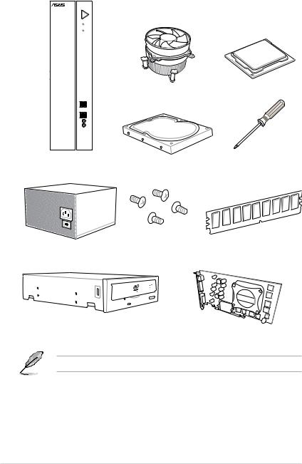
Installation tools and components
|
|
|
|
|
|
|
|
|
|
|
|
|
|
|
|
|
|
|
|
|
|
|
|
|
|
|
|
|
|
|
|
|
|
|
|
|
|
|
|
|
|
Intel® LGA1151 compatible CPU Fan |
Intel® LGA1151 CPU |
|
|
|
|
|
|
|
|
|
|
|
|
|
|
|
|
|
|
|
|
|
|
|
|
|
|
|
|
|
|
|
|
|
|
|
|
|
|
|
|
|
|
|
|
|
|
PC chassis |
SATA hard disk drive |
Phillips (cross) screwdriver |
Power supply unit |
1 bag of screws |
DIMM |
SATA optical disc drive (optional) |
Graphics card |
The tools and components in the table above are not included in the motherboard package.
xii

Product Introduction |
1 |
1.1Motherboard overview
1.1.1Before you proceed
Take note of the following precautions before you install motherboard components or change any motherboard settings.
•Unplug the power cord from the wall socket before touching any component.
•Before handling components, use a grounded wrist strap or touch a safely grounded object or a metal object, such as the power supply case, to avoid damaging them due to static electricity.
•Hold components by the edges to avoid touching the ICs on them.
•Whenever you uninstall any component, place it on a grounded antistatic pad or in the bag that came with the component.
•Before you install or remove any component, ensure that the ATX power supply is switched off or the power cord is detached from the power supply. Failure to do so may cause severe damage to the motherboard, peripherals, or components.
Chapter 1
ASUS WS C246M PRO |
1-1 |

1.1.2Motherboard layout
1 Chapter
Refer to 1.1.9 Internal connectors and 2.3.1 Rear I/O connection for more information about rear panel connectors and internal connectors.
1-2 |
Chapter 1: Product Introduction |

Layout contents
Connectors/Jumpers/Buttons and switches/Slots |
Page |
|
1. |
DDR4 DIMM slots |
1-5 |
2. |
ATX power connectors (24-pin EATXPWR1; 8-pin EATX12V1) |
1-24 |
3. |
Smart Ride Through (SmaRT) setting (3-pin SMART_PSU1) |
1-11 |
4. |
Power Supply SMBus connector (5-pin PSUSMB1) |
1-25 |
5. |
System Management Bus (SMBUS) connector (5-1 pin SMBUS1) |
1-26 |
6. |
Fan connectors (4-pin CPU_FAN1; 4-pin FRNT_FAN1-3; |
1-21 |
|
4-pin REAR_FAN1) |
|
7. |
M.2 (NGFF) connector (NGFF1) |
1-28 |
8. |
USB 2.0 connectors (10-1 pin USB34, USB78) |
1-20 |
9. |
BIOS Flashback button |
2-11 |
|
|
|
10. |
ME firmware force recovery setting (3-pin ME_RCVR1) |
1-10 |
11. |
Intel® Serial ATA 6 Gb/s connectors (7-pin SATA6G_1-8) |
1-17 |
12. |
Serial General Purpose Input/Output connector (6-1 pin SGPIO1) |
1-25 |
13. |
Auxiliary panel connector (20-2 pin AUX_PANEL1) |
1-23 |
14. |
System panel connector (20-1 pin PANEL1) |
1-22 |
15. |
PCH_MFG1 setting (3-pin PCH_MFG1) |
1-11 |
16. |
USB 3.1 Gen 1 connector (20-1 pin USB3_12) |
1-19 |
17. |
Storage device activity LED connector (4-pin HDLED1) |
1-20 |
18. |
Chassis Intrusion (2-pin INTRUSION1) |
1-26 |
19. |
Q-Code LED |
1-16 |
20. |
Serial port connector (10-1 pin COM1) |
1-19 |
21. |
TPM connector (14-1 pin TPM1) |
1-18 |
22. |
Digital audio connector (4-1 pin SPDIF_OUT1) |
1-21 |
23. |
Front panel audio connector (10-1 pin AAFP) |
1-18 |
24. |
Clear RTC RAM (3-pin CLRTC1) |
1-9 |
25. |
Thermal sensor cable connector (3-pin TR1) |
1-23 |
26. |
Power-on button |
1-8 |
27. |
LGA1151 CPU socket |
1-4 |
28. |
LAN controller setting (3-pin LAN_SW2) |
1-10 |
Chapter 1
ASUS WS C246M PRO |
1-3 |

1.1.3Central Processing Unit (CPU)
The motherboard comes with a surface mount LGA1151 socket designed for the Intel® Xeon® Processor E Family (Coffee Lake) / Intel® Pentium™ processors / Intel® Celeron™ processors.
1 Chapter
Ensure that you install the correct CPU designed for LGA1151 socket only. DO NOT install a CPU designed for other sockets on the LGA1151 socket.
•Ensure that all power cables are unplugged before installing the CPU.
•Upon purchase of the motherboard, ensure that the PnP cap is on the socket and the socket contacts are not bent. Contact your retailer immediately if the PnP cap is missing, or if you see any damage to the PnP cap/socket contacts/motherboard components. ASUS will shoulder the cost of repair only if the damage is shipment/ transit-related.
•Keep the cap after installing the motherboard. ASUS will process Return Merchandise Authorization (RMA) requests only if the motherboard comes with the cap on the LGA2066 socket.
•The product warranty does not cover damage to the socket contacts resulting from incorrect CPU installation/removal, or misplacement/loss/incorrect removal of the PnP cap.
1-4 |
Chapter 1: Product Introduction |
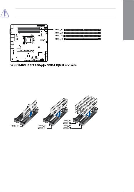
1.1.4System memory
The motherboard comes with four DDR 4 (Double Data Rate 4) Dual Inline Memory Modules (DIMM) slots.
A DDR4 module is notched differently from a DDR, DDR2 or DDR3 module. DO NOT install a DDR, DDR2 or DDR3 memory module to the DDR4 slot.
Recommended memory configurations
Chapter 1
ASUS WS C246M PRO |
1-5 |

1 Chapter
Memory configurations
You may install 2 GB, 4 GB, 8 GB and 16 GB unbuffered and ECC and non ECC DDR4 DIMMs into the DIMM sockets.
You may install varying memory sizes in Channel A and Channel B. The system maps the total size of the lower-sized channel for the dual-channel configuration. Any excess memory from the higher-sized channel is then mapped for single-channel operation.
• The default memory operation frequency is dependent on its Serial Presence Detect (SPD), which is the standard way of accessing information from a memory module. Under the default state, some memory modules for overclocking may operate at a lower frequency than the vendor-marked value.
•For system stability, use a more efficient memory cooling system to support a full memory load (8 DIMMs) or overclocking condition.
•Always install the DIMMS with the same CAS Latency. For an optimum compatibility, we recommend that you install memory modules of the same version or data code (D/C) from the same vendor. Check with the vendor to get the correct memory modules.
•Visit the ASUS website for the latest QVL.
1-6 |
Chapter 1: Product Introduction |

1.1.5Expansion slots
Unplug the power cord before adding or removing expansion cards. Failure to do so may cause you physical injury and damage motherboard components.
Chapter 1
|
|
|
|
|
|
|
|
|
|
|
|
|
|
|
|
|
|
|
|
|
|
|
|
|
|
|
|
|
|
|
|
|
|
|
|
|
|
|
|
|
|
|
|
|
|
|
|
|
|
|
|
|
|
|
|
|
|
|
|
|
|
|
|
|
|
|
|
|
|
|
|
|
|
|
|
|
|
|
|
|
|
|
|
|
|
|
|
|
|
|
|
|
|
|
|
|
|
|
|
|
|
|
|
|
|
|
|
|
|
|
|
|
|
|
|
|
|
|
|
|
|
|
|
|
|
|
|
|
|
|
|
|
|
|
|
|
|
|
|
|
|
|
|
|
|
|
|
|
|
|
|
|
|
|
|
|
|
|
|
|
|
|
|
|
|
|
|
|
|
|
|
|
|
|
|
|
|
|
|
|
|
|
|
|
|
|
|
|
|
|
|
|
|
|
|
|
|
|
|
|
|
|
|
|
|
|
|
|
|
|
|
|
|
|
|
|
|
|
|
|
|
|
|
|
|
|
|
|
|
|
|
|
|
|
|
|
|
|
|
|
|
|
|
|
|
|
|
|
|
|
|
|
|
|
|
|
|
|
|
|
|
|
|
|
|
|
|
|
|
|
|
|
|
|
|
|
|
|
|
|
|
|
|
|
|
|
|
|
|
|
|
|
|
|
|
|
|
|
|
|
|
|
|
|
|
|
|
|
|
|
|
|
|
|
|
|
|
|
|
|
|
|
|
|
|
|
|
|
|
|
|
|
|
|
|
|
|
|
|
|
|
|
|
|
|
|
|
|
|
|
|
|
|
|
|
|
|
|
|
|
|
|
|
|
|
|
|
|
|
|
|
|
|
|
|
|
|
|
|
|
|
|
|
|
|
|
|
|
|
|
|
|
|
|
|
|
|
|
|
|
|
|
|
|
|
|
|
|
|
|
|
|
|
|
|
|
|
|
|
|
|
|
|
|
|
|
|
|
|
|
|
|
|
|
|
|
|
|
|
|
|
|
|
|
|
|
|
|
|
|
|
|
|
|
|
|
|
|
|
|
|
|
|
|
|
|
|
|
|
|
|
|
|
|
|
|
|
|
|
|
|
|
|
|
|
|
|
|
|
|
|
|
|
|
|
|
|
|
|
|
|
|
|
|
|
|
|
|
|
|
|
|
|
|
|
|
|
|
|
|
|
|
|
|
|
|
|
|
|
|
|
|
|
|
|
|
|
|
|
|
|
|
|
|
|
|
|
|
|
|
|
|
|
|
|
|
|
|
|
|
|
|
|
|
|
|
|
|
|
|
|
|
|
|
|
|
|
|
|
|
|
|
|
|
|
|
|
|
|
|
|
|
|
|
|
|
|
|
|
|
|
|
|
|
|
|
|
|
|
|
|
|
|
|
|
|
|
|
|
|
|
|
|
|
|
|
|
|
|
|
|
|
|
|
|
|
|
|
|
|
|
|
|
|
|
|
|
|
|
|
|
|
|
|
|
|
|
|
|
|
|
|
|
|
|
|
|
|
|
|
|
|
|
|
|
|
|
|
|
|
|
|
|
|
|
|
|
|
|
|
|
|
|
|
|
|
|
|
|
|
|
|
|
|
|
|
|
|
|
|
|
|
|
|
|
|
|
|
|
|
|
|
|
|
|
|
|
|
|
|
|
|
|
|
|
|
|
|
|
|
|
|
|
|
|
|
|
|
|
|
|
|
|
|
|
|
|
|
|
|
|
|
|
|
|
|
|
|
|
|
|
|
|
|
|
|
|
|
|
|
|
|
|
|
|
|
|
|
|
|
|
|
|
|
|
|
|
|
|
|
|
|
|
|
|
|
|
|
|
|
|
|
|
|
|
|
|
|
|
|
|
|
|
|
|
|
|
|
|
|
|
|
|
|
|
|
|
|
|
|
|
|
|
|
|
|
|
|
|
|
|
|
|
|
|
|
|
|
|
|
|
|
|
|
|
|
|
|
|
|
|
|
|
|
|
|
|
|
|
|
|
|
|
|
|
|
|
|
|
|
|
|
|
|
|
|
|
|
|
|
|
|
|
|
|
|
|
|
|
|
|
|
|
|
|
|
|
|
|
|
|
|
|
|
|
|
|
|
|
|
|
|
|
|
|
|
|
|
|
|
|
|
|
|
|
|
|
|
|
|
|
|
|
|
|
|
|
|
|
|
|
|
|
|
|
|
|
|
|
|
|
|
|
|
|
|
|
|
|
|
|
|
|
|
|
|
|
|
|
|
|
|
|
|
|
|
|
|
|
|
|
|
|
|
|
|
|
|
|
|
|
|
|
|
|
|
|
|
|
|
|
|
|
|
|
|
|
|
|
|
|
|
|
|
|
|
|
|
|
|
|
|
|
|
|
|
|
|
|
|
|
|
|
|
|
|
|
|
|
|
|
|
|
|
|
|
|
|
|
|
|
|
|
|
|
|
|
|
|
|
|
|
|
|
|
|
|
|
|
|
|
|
|
|
|
|
|
|
|
|
|
|
|
|
|
|
|
|
|
|
|
|
|
|
|
|
|
|
|
|
|
|
|
|
|
|
|
|
|
|
|
|
|
|
|
|
|
|
|
|
|
|
|
|
|
|
|
|
|
|
|
|
|
|
|
|
|
|
|
|
|
|
|
|
|
|
|
|
|
|
|
|
|
|
|
|
|
|
|
|
|
|
|
|
|
|
|
|
|
|
|
|
|
|
|
|
|
|
|
|
|
|
|
|
|
|
|
|
|
|
|
|
|
|
|
|
|
|
|
|
|
|
|
|
|
|
|
|
|
|
|
|
|
|
|
|
|
|
|
|
|
|
|
|
|
|
|
|
|
|
|
|
|
|
|
|
|
|
|
|
|
|
|
|
|
|
|
|
|
|
|
|
|
|
|
|
|
|
|
|
|
|
|
|
|
|
|
|
|
|
|
|
|
|
|
|
|
|
|
|
|
|
|
|
|
|
|
|
|
|
|
|
|
|
|
|
|
|
|
|
|
|
|
|
|
|
|
|
|
|
|
|
|
|
|
|
|
|
|
|
|
|
|
|
|
|
|
|
|
|
|
|
|
|
|
|
|
|
|
|
|
|
|
|
|
|
|
|
|
|
|
|
|
|
|
|
|
|
|
|
|
|
|
|
|
|
|
|
|
|
|
|
|
|
|
|
|
|
|
|
|
|
|
|
|
|
|
|
|
|
|
|
|
|
|
|
|
|
|
|
|
|
|
|
|
|
|
|
|
|
|
|
|
|
|
|
|
|
|
|
|
|
|
|
|
|
|
|
|
|
|
|
|
|
|
|
|
|
|
|
|
|
|
|
|
|
|
|
|
|
|
|
|
|
|
|
|
|
|
|
|
|
|
|
|
|
|
|
|
|
|
|
|
|
|
|
|
|
|
|
|
|
|
|
|
|
|
|
|
|
|
|
|
|
|
|
|
|
|
|
|
|
|
|
|
|
|
|
|
Slot No. |
Slot Description |
|||||||||||||||||||||||||||||||||||||||||||||||||
|
|
|
|
|
|
|
|
|
|
|
|
|
|
|
|
|
|
|
|
|
|
|
|
|
|
|
|
|
|
|
|
|
|
|
|
|
|
|
|
|
|
|
|
|
|
|
|
|
|
|
1 |
|
PCIE x1_1 slot |
||||||||||||||||||||||||||||||||||||||||||||||||
2 |
|
PCIE x16_1 slot |
||||||||||||||||||||||||||||||||||||||||||||||||
3 |
|
PCIE x8_1 slot |
||||||||||||||||||||||||||||||||||||||||||||||||
|
PCI Express 3.0 operating mode |
|
|
VGA / PCIe configuration |
Single VGA / PCIe card |
|
|
PCIe 3.0 x1_1 |
N/A |
|
|
PCIe 3.0 x16_1 |
X16 |
|
|
PCIe 3.0 x8_1 |
N/A |
|
|
ASUS WS C246M PRO |
1-7 |

|
1.1.6 |
|
|
|
|
|
|
|
|
Onboard buttons and switches |
||||||||||||||||||||||||||||||||||||||
|
Onboard buttons and switches allow you to fine-tune performance when working on a bare or |
|||||||||||||||||||||||||||||||||||||||||||||||
|
open-case system. This is ideal for overclockers and gamers who continually change settings |
|||||||||||||||||||||||||||||||||||||||||||||||
Chapter |
to enhance system performance. |
|||||||||||||||||||||||||||||||||||||||||||||||
1. |
Power-on button |
|||||||||||||||||||||||||||||||||||||||||||||||
|
||||||||||||||||||||||||||||||||||||||||||||||||
|
|
The motherboard comes with a power-on button that allows you to power up or wake |
||||||||||||||||||||||||||||||||||||||||||||||
|
|
up the system. The LED near the button also lights up when the system is plugged to |
||||||||||||||||||||||||||||||||||||||||||||||
1 |
|
a power source indicating that you should shut down the system and unplug the power |
||||||||||||||||||||||||||||||||||||||||||||||
|
cable before removing or installing any motherboard component. |
|||||||||||||||||||||||||||||||||||||||||||||||
|
|
|||||||||||||||||||||||||||||||||||||||||||||||
|
|
|
|
|
|
|
|
|
|
|
|
|
|
|
|
|
|
|
|
|
|
|
|
|
|
|
|
|
|
|
|
|
|
|
|
|
|
|
|
|
|
|
|
|
|
|
|
|
|
|
|
|
|
|
|
|
|
|
|
|
|
|
|
|
|
|
|
|
|
|
|
|
|
|
|
|
|
|
|
|
|
|
|
|
|
|
|
|
|
|
|
|
|
|
|
|
|
|
|
|
|
|
|
|
|
|
|
|
|
|
|
|
|
|
|
|
|
|
|
|
|
|
|
|
|
|
|
|
|
|
|
|
|
|
|
|
|
|
|
|
|
|
|
|
|
|
|
|
|
|
|
|
|
|
|
|
|
|
|
|
|
|
|
|
|
|
|
|
|
|
|
|
|
|
|
|
|
|
|
|
|
|
|
|
|
|
|
|
|
|
|
|
|
|
|
|
|
|
|
|
|
|
|
|
|
|
|
|
|
|
|
|
|
|
|
|
|
|
|
|
|
|
|
|
|
|
|
|
|
|
|
|
|
|
|
|
|
|
|
|
|
|
|
|
|
|
|
|
|
|
|
|
|
|
|
|
|
|
|
|
|
|
|
|
|
|
|
|
|
|
|
|
|
|
|
|
|
|
|
|
|
|
|
|
|
|
|
|
|
|
|
|
|
|
|
|
|
|
|
|
|
|
|
|
|
|
|
|
|
|
|
|
|
|
|
|
|
|
|
|
|
|
|
|
|
|
|
|
|
|
|
|
|
|
|
|
|
|
|
|
|
|
|
|
|
|
|
|
|
|
|
|
|
|
|
|
|
|
|
|
|
|
|
|
|
|
|
|
|
|
|
|
|
|
|
|
|
|
|
|
|
|
|
|
|
|
|
|
|
|
|
|
|
|
|
|
|
|
|
|
|
|
|
|
|
|
|
|
|
|
|
|
|
|
|
|
|
|
|
|
|
|
|
|
|
|
|
|
|
|
|
|
|
|
|
|
|
|
|
|
|
|
|
|
|
|
|
|
|
|
|
|
|
|
|
|
|
|
|
|
|
|
|
|
|
|
|
|
|
|
|
|
|
|
|
|
|
|
|
|
|
|
|
|
|
|
|
|
|
|
|
|
|
|
|
|
|
|
|
|
|
|
|
|
|
|
|
|
|
|
|
|
|
|
|
|
|
|
|
|
|
|
|
|
|
|
|
|
|
|
|
|
|
|
|
|
|
|
|
|
|
|
|
|
|
|
|
|
|
|
|
|
|
|
|
|
|
|
|
|
|
|
|
|
|
|
|
|
|
|
|
|
|
|
|
|
|
|
|
|
|
|
|
|
|
|
|
|
|
|
|
|
|
|
|
|
|
|
|
|
|
|
|
|
|
|
|
|
|
|
|
|
|
|
|
|
|
|
|
|
|
|
|
|
|
|
|
|
|
|
|
|
|
|
|
|
|
|
|
|
|
|
|
|
|
|
|
|
|
|
|
|
|
|
|
|
|
|
|
|
|
|
|
|
|
|
|
|
|
|
|
|
|
|
|
|
|
|
|
|
|
|
|
|
|
|
|
|
|
|
|
|
|
|
|
|
|
|
|
|
|
|
|
|
|
|
|
|
|
|
|
|
|
|
|
|
|
|
|
|
|
|
|
|
|
|
|
|
|
|
|
|
|
|
|
|
|
|
|
|
|
|
|
|
|
|
|
|
|
|
|
|
|
|
|
|
|
|
|
|
|
|
|
|
|
|
|
|
|
|
|
|
|
|
|
|
|
|
|
|
|
|
|
|
|
|
|
|
|
|
|
|
|
|
|
|
|
|
|
|
|
|
|
|
|
|
|
|
|
|
|
|
|
|
|
|
|
|
|
|
|
|
|
|
|
|
|
|
|
|
|
|
|
|
|
|
|
|
|
|
|
|
|
|
|
|
|
|
|
|
|
|
|
|
|
|
|
|
|
|
|
|
|
|
|
|
|
|
|
|
|
|
|
|
|
|
|
|
|
|
|
|
|
|
|
|
|
|
|
|
|
|
|
|
|
|
|
|
|
|
|
|
|
|
|
|
|
|
|
|
|
|
|
|
|
|
|
|
|
|
|
|
|
|
|
|
|
|
|
|
1-8 |
Chapter 1: Product Introduction |
1.1.7Jumpers
1. |
Clear RTC RAM (3-pin CLRTC1) |
|
|
|
This jumper allows you to clear the Real Time Clock (RTC) RAM in CMOS. You can |
|
|
|
clear the CMOS memory of date, time, and system setup parameters by erasing the |
1 |
|
|
CMOS RTC RAM data. The onboard button cell battery powers the RAM data in |
||
|
Chapter |
||
|
CMOS, which include system setup information such as system passwords. |
||
|
|
||
|
To erase the RTC RAM: |
|
|
|
1. |
Turn OFF the computer and unplug the power cord. |
|
|
2. |
Move the jumper cap from pins 1-2 (default) to pins 2-3. Keep the cap on pins 2-3 |
|
|
|
for about 5-10 seconds, then move the cap back to pins 1-2. |
|
|
|
|
|
|
3. |
Plug the power cord and turn ON the computer. |
|
|
4. |
Hold down the <Del> key during the boot process and enter BIOS setup to |
|
|
|
reenter data. |
|
Except when clearing the RTC RAM, never short-circuit the CLRTC1 jumper. Shorting the
CLRTC1 jumper will cause system boot failure!
If the steps above do not help, remove the onboard battery and move the jumper again to clear the CMOS RTC RAM data. After the CMOS clearance, reinstall the battery.
|
|
|
|
|
|
|
|
|
|
|
|
|
|
|
|
|
|
|
|
|
|
|
|
|
|
|
|
|
|
|
|
|
|
|
|
|
|
|
|
|
|
|
|
|
|
|
|
|
|
|
|
|
|
|
|
|
|
|
|
|
|
|
|
|
|
|
|
|
|
|
|
|
|
|
|
|
|
|
|
|
|
|
|
|
|
|
|
|
|
|
|
|
|
|
|
|
|
|
|
|
|
|
|
|
|
|
|
|
|
|
|
|
|
|
|
|
|
|
|
|
|
|
|
|
|
|
|
|
|
|
|
|
|
|
|
|
|
|
|
|
|
|
|
|
|
|
|
|
|
|
|
|
|
|
|
|
|
|
|
|
|
|
|
|
|
|
|
|
|
|
|
|
|
|
|
|
|
|
|
|
|
|
|
|
|
|
|
|
|
|
|
|
|
|
|
|
|
|
|
|
|
|
|
|
|
|
|
|
|
|
|
|
|
|
|
|
|
|
|
|
|
|
|
|
|
|
|
|
|
|
|
|
|
|
|
|
|
|
|
|
|
|
|
|
|
|
|
|
|
|
|
|
|
|
|
|
|
|
|
|
|
|
|
|
|
|
|
|
|
|
|
|
|
|
|
|
|
|
|
|
|
|
|
|
|
|
|
|
|
|
|
|
|
|
|
|
|
|
|
|
|
|
|
|
|
|
|
|
|
|
|
|
|
|
|
|
|
|
|
|
|
|
|
|
|
|
|
|
|
|
|
|
|
|
|
|
|
|
|
|
|
|
|
|
|
|
|
|
|
|
|
|
|
|
|
|
|
|
|
|
|
|
|
|
|
|
|
|
|
|
|
|
|
|
|
|
|
|
|
|
|
|
|
|
|
|
|
|
|
|
|
|
|
|
|
|
|
|
|
|
|
|
|
|
|
|
|
|
|
|
|
|
|
|
|
|
|
|
|
|
|
|
|
|
|
|
|
|
|
|
|
|
|
|
|
|
|
|
|
|
|
|
|
|
|
|
|
|
|
|
|
|
|
|
|
|
|
|
|
|
|
|
|
|
|
|
|
|
|
|
|
|
|
|
|
|
|
|
|
|
|
|
|
|
|
|
|
|
|
|
|
|
|
|
|
|
|
|
|
|
|
|
|
|
|
|
|
|
|
|
|
|
|
|
|
|
|
|
|
|
|
|
|
|
|
|
|
|
|
|
|
|
|
|
|
|
|
|
|
|
|
|
|
|
|
|
|
|
|
|
|
|
|
|
|
|
|
|
|
|
|
|
|
|
|
|
|
|
|
|
|
|
|
|
|
|
|
|
|
|
|
|
|
|
|
|
|
|
|
|
|
|
|
|
|
|
|
|
|
|
|
|
|
|
|
|
|
|
|
|
|
|
|
|
|
|
|
|
|
|
|
|
|
|
|
|
|
|
|
|
|
|
|
|
|
|
|
|
|
|
|
|
|
|
|
|
|
|
|
|
|
|
|
|
|
|
|
|
|
|
|
|
|
|
|
|
|
|
|
|
|
|
|
|
|
|
|
|
|
|
|
|
|
|
|
|
|
|
|
|
|
|
|
|
|
|
|
|
|
|
|
|
|
|
|
|
|
|
|
|
|
|
|
|
|
|
|
|
|
|
|
|
|
|
|
|
|
|
|
|
|
|
|
|
|
|
|
|
|
|
|
|
|
|
|
|
|
|
|
|
|
|
|
|
|
|
|
|
|
|
|
|
|
|
|
|
|
|
|
|
|
|
|
|
|
|
|
|
|
|
|
|
|
|
|
|
|
|
|
|
|
|
|
|
|
|
|
|
|
|
|
|
|
|
|
|
|
|
|
|
|
|
|
|
|
|
|
|
|
|
|
|
|
|
|
|
|
|
|
|
|
|
|
|
|
|
|
|
|
|
|
|
|
|
|
|
|
|
|
|
|
|
|
|
|
|
|
|
|
|
|
|
|
|
|
|
|
|
|
|
|
|
|
|
|
|
|
|
|
|
|
|
|
|
|
|
|
|
|
|
|
|
|
|
|
|
|
|
|
ASUS WS C246M PRO |
1-9 |
|||||||||||||||||||||||||||||||||||||||||||

2.LAN controller setting (3-pin LAN_SW2)
This jumper allows you to enable or disable the onboard Intel® I210-AT Gigabit (LAN_ SW2) controller. Set to pins 1–2 to activate the Gigabit LAN feature.
1 Chapter
3.ME firmware force recovery setting (3-pin ME_RCVR1)
This jumper allows you to force Intel® Management Engine (ME) boot from recovery mode when ME becomes corrupted.
|
|
|
|
|
|
|
|
|
|
|
|
|
|
|
|
|
|
|
|
|
|
|
|
|
|
|
|
|
|
|
|
|
|
|
|
|
|
|
|
|
|
|
|
|
|
|
|
|
|
|
|
|
|
|
|
|
|
|
|
|
|
|
|
|
|
|
|
|
|
|
|
|
|
|
|
|
|
|
|
|
|
|
|
|
|
|
|
|
|
|
|
|
|
|
|
|
|
|
|
|
|
|
|
|
|
|
|
|
|
|
|
|
|
|
|
|
|
|
|
|
|
|
|
|
|
|
|
|
|
|
|
|
|
|
|
|
|
|
|
|
|
|
|
|
|
|
|
|
|
|
|
|
|
|
|
|
|
|
|
|
|
|
|
|
|
|
|
|
|
|
|
|
|
|
|
|
|
|
|
|
|
|
|
|
|
|
|
|
|
|
|
|
|
|
|
|
|
|
|
|
|
|
|
|
|
|
|
|
|
|
|
|
|
|
|
|
|
|
|
|
|
|
|
|
|
|
|
|
|
|
|
|
|
|
|
|
|
|
|
|
|
|
|
|
|
|
|
|
|
|
|
|
|
|
|
|
|
|
|
|
|
|
|
|
|
|
|
|
|
|
|
|
|
|
|
|
|
|
|
|
|
|
|
|
|
|
|
|
|
|
|
|
|
|
|
|
|
|
|
|
|
|
|
|
|
|
|
|
|
|
|
|
|
|
|
|
|
|
|
|
|
|
|
|
|
|
|
|
|
|
|
|
|
|
|
|
|
|
|
|
|
|
|
|
|
|
|
|
|
|
|
|
|
|
|
|
|
|
|
|
|
|
|
|
|
|
|
|
|
|
|
|
|
|
|
|
|
|
|
|
|
|
|
|
|
|
|
|
|
|
|
|
|
|
|
|
|
|
|
|
|
|
|
|
|
|
|
|
|
|
|
|
|
|
|
|
|
|
|
|
|
|
|
|
|
|
|
|
|
|
|
|
|
|
|
|
|
|
|
|
|
|
|
|
|
|
|
|
|
|
|
|
|
|
|
|
|
|
|
|
|
|
|
|
|
|
|
|
|
|
|
|
|
|
|
|
|
|
|
|
|
|
|
|
|
|
|
|
|
|
|
|
|
|
|
|
|
|
|
|
|
|
|
|
|
|
|
|
|
|
|
|
|
|
|
|
|
|
|
|
|
|
|
|
|
|
|
|
|
|
|
|
|
|
|
|
|
|
|
|
|
|
|
|
|
|
|
|
|
|
|
|
|
|
|
|
|
|
|
|
|
|
|
|
|
|
|
|
|
|
|
|
|
|
|
|
|
|
|
|
|
|
|
|
|
|
|
|
|
|
|
|
|
|
|
|
|
|
|
|
|
|
|
|
|
|
|
|
|
|
|
|
|
|
|
|
|
|
|
|
|
|
|
|
|
|
|
|
|
|
|
|
|
|
|
|
|
|
|
|
|
|
|
|
|
|
|
|
|
|
|
|
|
|
|
|
|
|
|
|
|
|
|
|
|
|
|
|
|
|
|
|
|
|
|
|
|
|
|
|
|
|
|
|
|
|
|
|
|
|
|
|
|
|
|
|
|
|
|
|
|
|
|
|
|
|
|
|
|
|
|
|
|
|
|
|
|
|
|
|
|
|
|
|
|
|
|
|
|
|
|
|
|
|
|
|
|
|
|
|
|
|
|
|
|
|
|
|
|
|
|
|
|
|
|
|
|
|
|
|
|
|
|
|
|
|
|
|
|
|
|
|
|
|
|
|
|
|
|
|
|
|
|
|
|
|
|
|
|
|
|
|
|
|
|
|
|
|
|
|
|
|
|
|
|
|
|
|
|
|
|
|
|
|
|
|
|
|
|
|
|
|
|
|
|
|
|
|
|
|
|
1-10 |
|
|
|
|
|
|
|
|
|
|
|
|
|
|
|
|
|
|
|
|
|
|
|
|
|
|
|
|
|
|
|
|
|
|
|
|
|
|
|
|
|
|
|
|
|
|
|
|
|
|
Chapter 1: Product Introduction |
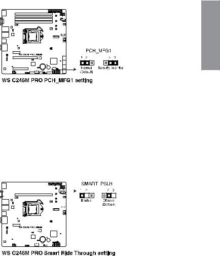
4.PCH_MFG1 setting (3-pin PCH_MFG1)
This jumper allows you to update the BIOS ME block.
Chapter 1
5.Smart Ride Through (SmaRT) setting (3-pin SMART_PSU1)
This jumper allows you to enable or disable the Smart Ride Through (SmaRT) function. This feature is enabled by default. Set to pins 2-3 to disable it. When enabled, SmaRT allows uninterrupted operation of the system during an AC loss event.
|
|
|
|
|
|
|
|
|
|
|
|
|
|
|
|
|
|
|
|
|
|
|
|
|
|
|
|
|
|
|
|
|
|
|
|
|
|
|
|
|
|
|
|
|
|
|
|
|
|
|
|
|
|
|
|
|
|
|
|
|
|
|
|
|
|
|
|
|
|
|
|
|
|
|
|
|
|
|
|
|
|
|
|
|
|
|
|
|
|
|
|
|
|
|
|
|
|
|
|
|
|
|
|
|
|
|
|
|
|
|
|
|
|
|
|
|
|
|
|
|
|
|
|
|
|
|
|
|
|
|
|
|
|
|
|
|
|
|
|
|
|
|
|
|
|
|
|
|
|
|
|
|
|
|
|
|
|
|
|
|
|
|
|
|
|
|
|
|
|
|
|
|
|
|
|
|
|
|
|
|
|
|
|
|
|
|
|
|
|
|
|
|
|
|
|
|
|
|
|
|
|
|
|
|
|
|
|
|
|
|
|
|
|
|
|
|
|
|
|
|
|
|
|
|
|
|
|
|
|
|
|
|
|
|
|
|
|
|
|
|
|
|
|
|
|
|
|
|
|
|
|
|
|
|
|
|
|
|
|
|
|
|
|
|
|
|
|
|
|
|
|
|
|
|
|
|
|
|
|
|
|
|
|
|
|
|
|
|
|
|
|
|
|
|
|
|
|
|
|
|
|
|
|
|
|
|
|
|
|
|
|
|
|
|
|
|
|
|
|
|
|
|
|
|
|
|
|
|
|
|
|
|
|
|
|
|
|
|
|
|
|
|
|
|
|
|
|
|
|
|
|
|
|
|
|
|
|
|
|
|
|
|
|
|
|
|
|
|
|
|
|
|
|
|
|
|
|
|
|
|
|
|
|
|
|
|
|
|
|
|
|
|
|
|
|
|
|
|
|
|
|
|
|
|
|
|
|
|
|
|
|
|
|
|
|
|
|
|
|
|
|
|
|
|
|
|
|
|
|
|
|
|
|
|
|
|
|
|
|
|
|
|
|
|
|
|
|
|
|
|
|
|
|
|
|
|
|
|
|
|
|
|
|
|
|
|
|
|
|
|
|
|
|
|
|
|
|
|
|
|
|
|
|
|
|
|
|
|
|
|
|
|
|
|
|
|
|
|
|
|
|
|
|
|
|
|
|
|
|
|
|
|
|
|
|
|
|
|
|
|
|
|
|
|
|
|
|
|
|
|
|
|
|
|
|
|
|
|
|
|
|
|
|
|
|
|
|
|
|
|
|
|
|
|
|
|
|
|
|
|
|
|
|
|
|
|
|
|
|
|
|
|
|
|
|
|
|
|
|
|
|
|
|
|
|
|
|
|
|
|
|
|
|
|
|
|
|
|
|
|
|
|
|
|
|
|
|
|
|
|
|
|
|
|
|
|
|
|
|
|
|
|
|
|
|
|
|
|
|
|
|
|
|
|
|
|
|
|
|
|
|
|
|
|
|
|
|
|
|
|
|
|
|
|
|
|
|
|
|
|
|
|
|
|
|
|
|
|
|
|
|
|
|
|
|
|
|
|
|
|
|
|
|
|
|
|
|
|
|
|
|
|
|
|
|
|
|
|
|
|
|
|
|
|
|
|
|
|
|
|
|
|
|
|
|
|
|
|
|
|
|
|
|
|
|
|
|
|
|
|
|
|
|
|
|
|
|
|
|
|
|
|
|
|
|
|
|
|
|
|
|
|
|
|
|
|
|
|
|
|
|
|
|
|
|
|
|
|
|
|
|
|
|
|
|
|
|
|
|
|
|
|
|
|
|
|
|
|
|
|
|
|
|
|
|
|
|
|
|
|
|
|
|
|
|
|
|
|
|
|
|
|
|
|
|
|
|
|
|
|
|
|
|
|
|
|
|
|
|
|
|
|
|
|
|
|
|
|
|
|
|
|
|
|
|
|
|
|
|
ASUS WS C246M PRO |
1-11 |
||||||||||||||||||||||||||||||||||||||||||||||||
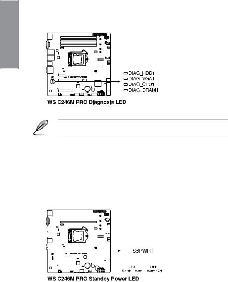
1.1.8Onboard LEDs
1. |
Diagnosis LEDs |
|
|
The Diagnosis LEDs provide the status of these key components during POST (Power- |
|
1Chapter |
On-Self Test): CPU, memory modules, VGA card, and hard disk drives. If an error is |
|
found, the critical component’s LED stays lit up until the problem is solved. |
||
|
The Diagnosis LEDs provide the most probable cause of an error code as a starting point for troubleshooting. The actual cause may vary from case to case.
2.Standby Power LED (SBPWR1)
The motherboard comes with a standby power LED. The green LED lights up to indicate that the system is ON, in sleep mode, or in soft-off mode. This is a reminder that you should shut down the system and unplug the power cable before removing or plugging in any motherboard component. The illustration below shows the location of the onboard LED.
|
|
|
|
|
|
|
|
|
|
|
|
|
|
|
|
|
|
|
|
|
|
|
|
|
|
|
|
|
|
|
|
|
|
|
|
|
|
|
|
|
|
|
|
|
|
|
|
|
|
|
|
|
|
|
|
|
|
|
|
|
|
|
|
|
|
|
|
|
|
|
|
|
|
|
|
|
|
|
|
|
|
|
|
|
|
|
|
|
|
|
|
|
|
|
|
|
|
|
|
|
|
|
|
|
|
|
|
|
|
|
|
|
|
|
|
|
|
|
|
|
|
|
|
|
|
|
|
|
|
|
|
|
|
|
|
|
|
|
|
|
|
|
|
|
|
|
|
|
|
|
|
|
|
|
|
|
|
|
|
|
|
|
|
|
|
|
|
|
|
|
|
|
|
|
|
|
|
|
|
|
|
|
|
|
|
|
|
|
|
|
|
|
|
|
|
|
|
|
|
|
|
|
|
|
|
|
|
|
|
|
|
|
|
|
|
|
|
|
|
|
|
|
|
|
|
|
|
|
|
|
|
|
|
|
|
|
|
|
|
|
|
|
|
|
|
|
|
|
|
|
|
|
|
|
|
|
|
|
|
|
|
|
|
|
|
|
|
|
|
|
|
|
|
|
|
|
|
|
|
|
|
|
|
|
|
|
|
|
|
|
|
|
|
|
|
|
|
|
|
|
|
|
|
|
|
|
|
|
|
|
|
|
|
|
|
|
|
|
|
|
|
|
|
|
|
|
|
|
|
|
|
|
|
|
|
|
|
|
|
|
|
|
|
|
|
|
|
|
|
|
|
|
|
|
|
|
|
|
|
|
|
|
|
|
|
|
|
|
|
|
|
|
|
|
|
|
|
|
|
|
|
|
|
|
|
|
|
|
|
|
|
|
|
|
|
|
|
|
|
|
|
|
|
|
|
|
|
|
|
|
|
|
|
|
|
|
|
|
|
|
|
|
|
|
|
|
|
|
|
|
|
|
|
|
|
|
|
|
|
|
|
|
|
|
|
|
|
|
|
|
|
|
|
|
|
|
|
|
|
|
|
|
|
|
|
|
|
|
|
|
|
|
|
|
|
|
|
|
|
|
|
|
|
|
|
|
|
|
|
|
|
|
|
|
|
|
|
|
|
|
|
|
|
|
|
|
|
|
|
|
|
|
|
|
|
|
|
|
|
|
|
|
|
|
|
|
|
|
|
|
|
|
|
|
|
|
|
|
|
|
|
|
|
|
|
|
|
|
|
|
|
|
|
|
|
|
|
|
|
|
|
|
|
|
|
|
|
|
|
|
|
|
|
|
|
|
|
|
|
|
|
|
|
|
|
|
|
|
|
|
|
|
|
|
|
|
|
|
|
|
|
|
|
|
|
|
|
|
|
|
|
|
|
|
|
|
|
|
|
|
|
|
|
|
|
|
|
|
|
|
|
|
|
|
|
|
|
|
|
|
|
|
|
|
|
|
|
|
|
|
|
|
|
|
|
|
|
|
|
|
|
|
|
|
|
|
|
|
|
|
|
1-12 |
|
|
|
|
|
|
|
|
|
|
|
|
|
|
|
|
|
|
|
|
|
|
|
|
|
|
|
|
|
|
|
|
|
|
|
|
|
|
|
|
|
|
|
|
|
|
Chapter 1: Product Introduction |

3.CPU Warning LED (ERRCPU1)
The CPU warning LED lights up to indicate that a CPU error or failure has occurred.
Chapter 1
4.Message LED (MLED1)
This onboard LED lights up to indicate that there is a temperature warning or a BMC event log is generated.
|
|
|
|
|
|
|
|
|
|
|
|
|
|
|
|
|
|
|
|
|
|
|
|
|
|
|
|
|
|
|
|
|
|
|
|
|
|
|
|
|
|
|
|
|
|
|
|
|
|
|
|
|
|
|
|
|
|
|
|
|
|
|
|
|
|
|
|
|
|
|
|
|
|
|
|
|
|
|
|
|
|
|
|
|
|
|
|
|
|
|
|
|
|
|
|
|
|
|
|
|
|
|
|
|
|
|
|
|
|
|
|
|
|
|
|
|
|
|
|
|
|
|
|
|
|
|
|
|
|
|
|
|
|
|
|
|
|
|
|
|
|
|
|
|
|
|
|
|
|
|
|
|
|
|
|
|
|
|
|
|
|
|
|
|
|
|
|
|
|
|
|
|
|
|
|
|
|
|
|
|
|
|
|
|
|
|
|
|
|
|
|
|
|
|
|
|
|
|
|
|
|
|
|
|
|
|
|
|
|
|
|
|
|
|
|
|
|
|
|
|
|
|
|
|
|
|
|
|
|
|
|
|
|
|
|
|
|
|
|
|
|
|
|
|
|
|
|
|
|
|
|
|
|
|
|
|
|
|
|
|
|
|
|
|
|
|
|
|
|
|
|
|
|
|
|
|
|
|
|
|
|
|
|
|
|
|
|
|
|
|
|
|
|
|
|
|
|
|
|
|
|
|
|
|
|
|
|
|
|
|
|
|
|
|
|
|
|
|
|
|
|
|
|
|
|
|
|
|
|
|
|
|
|
|
|
|
|
|
|
|
|
|
|
|
|
|
|
|
|
|
|
|
|
|
|
|
|
|
|
|
|
|
|
|
|
|
|
|
|
|
|
|
|
|
|
|
|
|
|
|
|
|
|
|
|
|
|
|
|
|
|
|
|
|
|
|
|
|
|
|
|
|
|
|
|
|
|
|
|
|
|
|
|
|
|
|
|
|
|
|
|
|
|
|
|
|
|
|
|
|
|
|
|
|
|
|
|
|
|
|
|
|
|
|
|
|
|
|
|
|
|
|
|
|
|
|
|
|
|
|
|
|
|
|
|
|
|
|
|
|
|
|
|
|
|
|
|
|
|
|
|
|
|
|
|
|
|
|
|
|
|
|
|
|
|
|
|
|
|
|
|
|
|
|
|
|
|
|
|
|
|
|
|
|
|
|
|
|
|
|
|
|
|
|
|
|
|
|
|
|
|
|
|
|
|
|
|
|
|
|
|
|
|
|
|
|
|
|
|
|
|
|
|
|
|
|
|
|
|
|
|
|
|
|
|
|
|
|
|
|
|
|
|
|
|
|
|
|
|
|
|
|
|
|
|
|
|
|
|
|
|
|
|
|
|
|
|
|
|
|
|
|
|
|
|
|
|
|
|
|
|
|
|
|
|
|
|
|
|
|
|
|
|
|
|
|
|
|
|
|
|
|
|
|
|
|
|
|
|
|
|
|
|
|
|
|
|
|
|
|
|
|
|
|
|
|
|
|
|
|
|
|
|
|
|
|
|
|
|
|
|
ASUS WS C246M PRO |
1-13 |
||||||||||||||||||||||||||||||||||||||||

5.BMC LED (BMCLED1)
The BMC LED lights up to indicate that the on-board BMC is functional.
1 Chapter
6.ME LED (MELED1)
The ME LED is an onboard LED that blinks when the ME is operating properly.
|
|
|
|
|
|
|
|
|
|
|
|
|
|
|
|
|
|
|
|
|
|
|
|
|
|
|
|
|
|
|
|
|
|
|
|
|
|
|
|
|
|
|
|
|
|
|
|
|
|
|
|
|
|
|
|
|
|
|
|
|
|
|
|
|
|
|
|
|
|
|
|
|
|
|
|
|
|
|
|
|
|
|
|
|
|
|
|
|
|
|
|
|
|
|
|
|
|
|
|
|
|
|
|
|
|
|
|
|
|
|
|
|
|
|
|
|
|
|
|
|
|
|
|
|
|
|
|
|
|
|
|
|
|
|
|
|
|
|
|
|
|
|
|
|
|
|
|
|
|
|
|
|
|
|
|
|
|
|
|
|
|
|
|
|
|
|
|
|
|
|
|
|
|
|
|
|
|
|
|
|
|
|
|
|
|
|
|
|
|
|
|
|
|
|
|
|
|
|
|
|
|
|
|
|
|
|
|
|
|
|
|
|
|
|
|
|
|
|
|
|
|
|
|
|
|
|
|
|
|
|
|
|
|
|
|
|
|
|
|
|
|
|
|
|
|
|
|
|
|
|
|
|
|
|
|
|
|
|
|
|
|
|
|
|
|
|
|
|
|
|
|
|
|
|
|
|
|
|
|
|
|
|
|
|
|
|
|
|
|
|
|
|
|
|
|
|
|
|
|
|
|
|
|
|
|
|
|
|
|
|
|
|
|
|
|
|
|
|
|
|
|
|
|
|
|
|
|
|
|
|
|
|
|
|
|
|
|
|
|
|
|
|
|
|
|
|
|
|
|
|
|
|
|
|
|
|
|
|
|
|
|
|
|
|
|
|
|
|
|
|
|
|
|
|
|
|
|
|
|
|
|
|
|
|
|
|
|
|
|
|
|
|
|
|
|
|
|
|
|
|
|
|
|
|
|
|
|
|
|
|
|
|
|
|
|
|
|
|
|
|
|
|
|
|
|
|
|
|
|
|
|
|
|
|
|
|
|
|
|
|
|
|
|
|
|
|
|
|
|
|
|
|
|
|
|
|
|
|
|
|
|
|
|
|
|
|
|
|
|
|
|
|
|
|
|
|
|
|
|
|
|
|
|
|
|
|
|
|
|
|
|
|
|
|
|
|
|
|
|
|
|
|
|
|
|
|
|
|
|
|
|
|
|
|
|
|
|
|
|
|
|
|
|
|
|
|
|
|
|
|
|
|
|
|
|
|
|
|
|
|
|
|
|
|
|
|
|
|
|
|
|
|
|
|
|
|
|
|
|
|
|
|
|
|
|
|
|
|
|
|
|
|
|
|
|
|
|
|
|
|
|
|
|
|
|
|
|
|
|
|
|
|
|
|
|
|
|
|
|
|
|
|
|
|
|
|
|
|
|
|
|
|
|
|
|
|
|
|
|
|
|
|
|
|
|
|
|
|
|
|
|
|
|
|
|
|
|
|
|
|
|
|
|
|
|
|
|
|
|
|
|
|
|
|
|
|
|
|
|
|
|
|
|
|
|
|
|
|
|
|
|
|
|
|
|
|
|
|
|
|
|
|
|
|
|
|
|
|
|
|
|
|
|
|
|
|
|
|
|
|
|
|
|
|
|
|
|
|
|
|
|
|
|
|
|
|
|
|
|
|
|
|
|
|
|
|
|
|
|
|
|
|
|
|
|
|
|
|
|
|
|
|
|
|
|
|
|
|
|
|
|
|
|
|
|
|
|
|
|
|
|
|
|
|
1-14 |
|
|
|
|
|
|
|
|
|
|
|
|
|
|
|
|
|
|
|
|
|
|
|
|
|
|
|
|
|
|
|
|
|
|
|
|
|
|
|
|
|
|
|
Chapter 1: Product Introduction |

7.CATT ERR LED (CATTERR1)
The CATT ERR LED indicates that the system has experienced a fatal or catastrophic error and cannot continue to operate.
Chapter 1
8.USB BIOS Flashback LED (FLBK_LED)
The BIOS Flashback LED flashes when you press the BIOS Flashback button for BIOS update.
|
|
|
|
|
|
|
|
|
|
|
|
|
|
|
|
|
|
|
|
|
|
|
|
|
|
|
|
|
|
|
|
|
|
|
|
|
|
|
|
|
|
|
|
|
|
|
|
|
|
|
|
|
|
|
|
|
|
|
|
|
|
|
|
|
|
|
|
|
|
|
|
|
|
|
|
|
|
|
|
|
|
|
|
|
|
|
|
|
|
|
|
|
|
|
|
|
|
|
|
|
|
|
|
|
|
|
|
|
|
|
|
|
|
|
|
|
|
|
|
|
|
|
|
|
|
|
|
|
|
|
|
|
|
|
|
|
|
|
|
|
|
|
|
|
|
|
|
|
|
|
|
|
|
|
|
|
|
|
|
|
|
|
|
|
|
|
|
|
|
|
|
|
|
|
|
|
|
|
|
|
|
|
|
|
|
|
|
|
|
|
|
|
|
|
|
|
|
|
|
|
|
|
|
|
|
|
|
|
|
|
|
|
|
|
|
|
|
|
|
|
|
|
|
|
|
|
|
|
|
|
|
|
|
|
|
|
|
|
|
|
|
|
|
|
|
|
|
|
|
|
|
|
|
|
|
|
|
|
|
|
|
|
|
|
|
|
|
|
|
|
|
|
|
|
|
|
|
|
|
|
|
|
|
|
|
|
|
|
|
|
|
|
|
|
|
|
|
|
|
|
|
|
|
|
|
|
|
|
|
|
|
|
|
|
|
|
|
|
|
|
|
|
|
|
|
|
|
|
|
|
|
|
|
|
|
|
|
|
|
|
|
|
|
|
|
|
|
|
|
|
|
|
|
|
|
|
|
|
|
|
|
|
|
|
|
|
|
|
|
|
|
|
|
|
|
|
|
|
|
|
|
|
|
|
|
|
|
|
|
|
|
|
|
|
|
|
|
|
|
|
|
|
|
|
|
|
|
|
|
|
|
|
|
|
|
|
|
|
|
|
|
|
|
|
|
|
|
|
|
|
|
|
|
|
|
|
|
|
|
|
|
|
|
|
|
|
|
|
|
|
|
|
|
|
|
|
|
|
|
|
|
|
|
|
|
|
|
|
|
|
|
|
|
|
|
|
|
|
|
|
|
|
|
|
|
|
|
|
|
|
|
|
|
|
|
|
|
|
|
|
|
|
|
|
|
|
|
|
|
|
|
|
|
|
|
|
|
|
|
|
|
|
|
|
|
|
|
|
|
|
|
|
|
|
|
|
|
|
|
|
|
|
|
|
|
|
|
|
|
|
|
|
|
|
|
|
|
|
|
|
|
|
|
|
|
|
|
|
|
|
|
|
|
|
|
|
|
|
|
|
|
|
|
|
|
|
|
|
|
|
|
|
|
|
|
|
|
|
|
|
|
|
|
|
|
|
|
|
|
|
|
|
|
|
|
|
|
|
|
|
|
|
|
|
|
|
|
|
|
|
|
|
|
|
|
|
|
|
|
|
|
|
|
|
|
|
|
|
|
|
|
|
|
|
|
|
|
|
|
|
|
|
|
|
|
|
|
|
|
|
|
|
|
|
|
|
|
|
|
|
|
|
|
|
|
|
|
|
|
|
|
|
|
|
|
|
|
|
|
|
|
|
|
|
|
|
|
|
|
|
|
|
|
|
|
|
|
|
|
|
|
|
|
|
|
|
|
|
|
|
|
|
|
|
|
|
|
|
|
|
|
|
|
|
|
|
|
|
|
|
|
|
|
|
|
|
|
|
|
|
|
|
|
|
ASUS WS C246M PRO |
1-15 |
|||||||||||||||||||||||||||||||||||||||||||

9.Q-Code LED
The Q-Code LED design provides you with a 2-digit error code that displays the system status.
1 Chapter
•The Q-Code LED provides the most probable cause of an error code as a starting point for troubleshooting. The actual cause may vary from case to case.
•Please refer to the Q-Code table in the Appendix section for more details.
1-16 |
Chapter 1: Product Introduction |

1.1.9Internal connectors
1. |
|
|
Intel® Serial ATA 6 Gb/s connectors (7-pin SATA6G_1-8) |
|
||||||||||||||||||||||||||||||||||||||||||||||||||||||||||||||
|
||||||||||||||||||||||||||||||||||||||||||||||||||||||||||||||||||
|
|
|
These connectors connect to Serial ATA 6 Gb/s hard disk drives via Serial ATA 6 Gb/s |
1 |
||||||||||||||||||||||||||||||||||||||||||||||||||||||||||||||
|
|
|
signal cables. |
|||||||||||||||||||||||||||||||||||||||||||||||||||||||||||||||
|
|
|
If you installed Serial ATA hard disk drives, you can create a RAID 0, 1, 5, and 10 |
Chapter |
||||||||||||||||||||||||||||||||||||||||||||||||||||||||||||||
|
|
|
configuration with the Intel® Rapid Storage Technology enterprise through the onboard |
|||||||||||||||||||||||||||||||||||||||||||||||||||||||||||||||
|
|
|
|
|||||||||||||||||||||||||||||||||||||||||||||||||||||||||||||||
|
|
|
Intel® C246 chipset. |
|
||||||||||||||||||||||||||||||||||||||||||||||||||||||||||||||
|
|
|
|
|
|
|
|
|
|
|
|
|
|
|
|
|
|
|
|
|
|
|
|
|
|
|
|
|
|
|
|
|
|
|
|
|
|
|
|
|
|
|
|
|
|
|
|
|
|
|
|
|
|
|
|
|
|
|
|
|
|
|
|
|
|
|
|
|
|
|
|
|
|
|
|
|
|
|
|
|
|
|
|
|
|
|
|
|
|
|
|
|
|
|
|
|
|
|
|
|
|
|
|
|
|
|
|
|
|
|
|
|
|
|
|
|
|
|
|
|
|
|
|
|
|
|
|
|
|
|
|
|
|
|
|
|
|
|
|
|
|
|
|
|
|
|
|
|
|
|
|
|
|
|
|
|
|
|
|
|
|
|
|
|
|
|
|
|
|
|
|
|
|
|
|
|
|
|
|
|
|
|
|
|
|
|
|
|
|
|
|
|
|
|
|
|
|
|
|
|
|
|
|
|
|
|
|
|
|
|
|
|
|
|
|
|
|
|
|
|
|
|
|
|
|
|
|
|
|
|
|
|
|
|
|
|
|
|
|
|
|
|
|
|
|
|
|
|
|
|
|
|
|
|
|
|
|
|
|
|
|
|
|
|
|
|
|
|
|
|
|
|
|
|
|
|
|
|
|
|
|
|
|
|
|
|
|
|
|
|
|
|
|
|
|
|
|
|
|
|
|
|
|
|
|
|
|
|
|
|
|
|
|
|
|
|
|
|
|
|
|
|
|
|
|
|
|
|
|
|
|
|
|
|
|
|
|
|
|
|
|
|
|
|
|
|
|
|
|
|
|
|
|
|
|
|
|
|
|
|
|
|
|
|
|
|
|
|
|
|
|
|
|
|
|
|
|
|
|
|
|
|
|
|
|
|
|
|
|
|
|
|
|
|
|
|
|
|
|
|
|
|
|
|
|
|
|
|
|
|
|
|
|
|
|
|
|
|
|
|
|
|
|
|
|
|
|
|
|
|
|
|
|
|
|
|
|
|
|
|
|
|
|
|
|
|
|
|
|
|
|
|
|
|
|
|
|
|
|
|
|
|
|
|
|
|
|
|
|
|
|
|
|
|
|
|
|
|
|
|
|
|
|
|
|
|
|
|
|
|
|
|
|
|
|
|
|
|
|
|
|
|
|
|
|
|
|
|
|
|
|
|
|
|
|
|
|
|
|
|
|
|
|
|
|
|
|
|
|
|
|
|
|
|
|
|
|
|
|
|
|
|
|
|
|
|
|
|
|
|
|
|
|
|
|
|
|
|
|
|
|
|
|
|
|
|
|
|
|
|
|
|
|
|
|
|
|
|
|
|
|
|
|
|
|
|
|
|
|
|
|
|
|
|
|
|
|
|
|
|
|
|
|
|
|
|
|
|
|
|
|
|
|
|
|
|
|
|
|
|
|
|
|
|
|
|
|
|
|
|
|
|
|
|
|
|
|
|
|
|
|
|
|
|
|
|
|
|
|
|
|
|
|
|
|
|
|
|
|
|
|
|
|
|
|
|
|
|
|
|
|
|
|
|
|
|
|
|
|
|
|
|
|
|
|
|
|
|
|
|
|
|
|
|
|
|
|
|
|
|
|
|
|
|
|
|
|
|
|
|
|
|
|
|
|
|
|
|
|
|
|
|
|
|
|
|
|
|
|
|
|
|
|
|
|
|
|
|
|
|
|
|
|
|
|
|
|
|
|
|
|
|
|
|
|
|
|
|
|
|
|
|
|
|
|
|
|
|
|
|
|
|
|
|
|
|
|
|
|
|
|
|
|
|
|
|
|
|
|
|
|
|
|
|
|
|
|
|
|
|
|
|
|
|
|
|
|
|
|
|
|
|
|
|
|
|
|
|
|
|
|
|
|
|
|
|
|
|
|
|
|
|
|
|
|
|
|
|
|
|
|
|
|
|
|
|
|
|
|
|
|
|
|
|
|
|
|
|
|
|
|
|
|
|
|
|
|
|
|
|
|
|
|
|
|
|
|
|
|
|
|
|
|
|
|
|
|
|
|
|
|
|
|
|
|
|
|
|
|
|
|
|
|
|
|
|
|
|
|
|
|
|
|
|
|
|
|
|
|
|
|
|
|
|
|
|
|
|
|
|
|
|
|
|
|
|
|
These connectors are set to [AHCI Mode] by default. If you intend to create a Serial ATA
RAID set using these connectors, set the SATA Mode item in the BIOS to [Intel RST
Premium (RAID)].
ASUS WS C246M PRO |
1-17 |

2.Front panel audio connector (10-1 pin AAFP)
This connector is for a chassis-mounted front panel audio I/O module that supports HD Audio. Connect one end of the front panel audio I/O module cable to this connector.
1 Chapter
We recommend that you connect a high-definition front panel audio module to this connector to avail of the motherboard’s high-definition audio capability.
3.TPM connector (14-1 pin TPM1)
This connector supports a Trusted Platform Module (TPM) system, which securely store keys, digital certificates, passwords and data. A TPM system also helps enhance network security, protect digital identities, and ensures platform integrity.
The TPM module is purchased separately.
1-18 |
Chapter 1: Product Introduction |
 Loading...