

Page 1
3
2
1,5m
C
1,5m
1,5m
m
m
1,5m
m
m
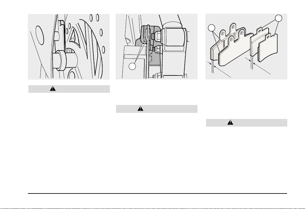
WARNING
Check the wear of the brake pads especially before every trip.
To carry on a quick check of the brake pad
wear:
♦ Position the vehicle on the central stand.
♦ Carry on a visual check between the brake
disk and the pads, proceeding:
FRONT BRAKE CALLIPER
– On the front, part from below, for both cal-
lipers.
REAR BRAKE CALLIPER
– On the rear part, from below, for both pads
(C).
WARNING
The excessive wear of the friction material would cause the contacts of the pad
metal support with the disk, with consequent metallic noise and production of
sparks from the calliper; braking efficiency, safety and soundness of the disk
would be compromised.
♦ If the thickness of the friction material (even
if of one pad only) has reduced to about
1.5 mm, have both pads replaced.
– Front pads (2).
– Rear pads (3).
WARNING
Have the pads replaced by your aprilia
Official Dealer.
use and maintenance
Atlantic 500
49
Page 2

CHECKING THE FRONT AND REAR
SUSPENSIONS
Carefully read page 39 (MAINTENANCE).
4
4
5
CHECKING THE STAND
Carefully read page 40 (MAINTENANCE).
FOR THE SIDE STAND ONLY
WARNING
Danger of fall or overturning
When straightening the vehicle, from the
parking position to the driving position,
the stand goes automatically up.
IMPORTANT The following information
refers to one stand only, but it is valid for
both.
use and maintenance Atlantic 500
50
The stand (4) must rotate without hindrances.
Carry on the following checks:
♦ The springs (5) must not be damaged,
worn, rusty or weakened.
♦ The stand must rotate without hindrances;
if necessary, grease the joint (see page 74
TABLE OF LUBRICANTS).
CHECKING THE SWITCHES
The vehicle is provided with two switches:
- Stoplight switch on the rear brake control
lever (combined)
- Stoplight switch on the front brake control
lever.
If you need assistance or technical advice,
contact your aprilia Official Dealer, who can
ensure you an accurate and prompt service.
To replace the front suspension oil con-
CAUTION
tact your aprilia Official Dealer, who can
ensure you an accurate and prompt service.
Have the front suspension oil changed every
30000 km (18750 miles) or every 4 years.
Carry on the following checks after the first
1000 km (625 miles) and successively after
6000 km (3750 miles):
♦ With pulled front brake lever, push the fork
repeatedly downwards. The stroke must be
smooth and there must not be any trace of
oil on the rods.
♦ Make sure that all components are fas-
tened and that the front and rear suspension joints work correctly.
CAUTION
Should you notice irregularities in the
operation or if the help of skilled personnel should be necessary, contact your
aprilia Official Dealer.
Page 3
1
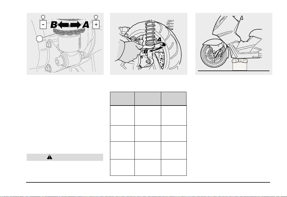
ADJUSTING THE REAR SUSPENSION
The rear suspension consists of a pair of
double-action shock absorbers (braking with
compressed/extended shock absorber) fastened to the engine by means of silentblocks.
The standard adjustment, set by the manufacturer, is suitable for a driver weighing
about 70 kg. In case of different weights or
needs, adjust the ring nut (1) by means of
the appropriate spanner provided in the tool
kit, thus setting the ideal drive conditions (see
table).
CAUTION
Set both shock absorbers on the same
position.
ADJUSTMENT OF THE REAR SUSPENSION SPRING PRELOAD
Adjusting
ring nut
Function
Attitude
Suggested
kind of
road
Notes
Rotation
(arrow A)
Spring
preload
increase
The vehicle
is more rigid
Smooth or
normal roads
Drive with
passenger
Rotation
(arrow B)
Spring
preload
decrease
The vehicle
is less rigid
Uneven
roads
Drive
without
passenger
CHECKING THE STEERING
Carefully read page 40 (MAINTENANCE).
It is necessary to check the steering slack
occasionally.
To carry on the check:
♦ Position the vehicle on the central stand.
IMPORTANT Provide for a support with
height and rest surface suitable to support
the vehicle safely.
♦ Place the support under the vehicle and a
spongy cloth between them, so that the
front wheel can move freely and the vehicle cannot fall down.
use and maintenance
Atlantic 500
51
Page 4
1
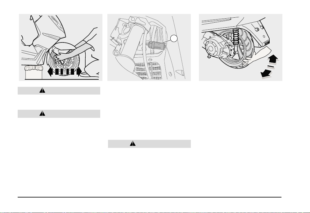
Make sure that the vehicle is stable.
♦ Shake the fork in the riding direction.
CAUTION
If you shake the fork excessively, the
stand will move, thus producing an incorrect slack. Repeat the previous operation
more than once.
♦ If the slack is considerable, contact your
aprilia Official Dealer, who will restore the
optimal operating conditions.
use and maintenance Atlantic 500
52
CAUTION
STEERING SHOCK ABSORBER
Carefully read page 40 (MAINTENANCE).
In case of full load trips (driver + passenger
+ luggage), it is possible to adjust the steering shock absorber.
To adjust the steering shock absorber:
♦ If you rotate the ring nut (1) clockwise, the
shock absorber becomes more rigid.
CAUTION
If you tighten the ring nut, the shock absorber becomes more rigid and consequently the effort to be made to rotate the
handlebar increases, thus reducing the
manoeuvrability.
CHECKING THE ENGINE FULCRUM
AXIS
Carefully read page 40 (MAINTENANCE).
Periodically check the slack between the
engine pin bushes.
To carry on the check:
♦ Position the vehicle on the central stand.
♦ Shake the wheel transversally with respect
to the riding direction.
♦ If you notice some slack, contact your
aprilia Official Dealer, who will restore the
optimal operating conditions.
Page 5
1
2
3
2
3
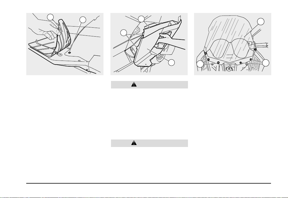
REMOVING THE RIGHT AND LEFT
INSPECTION COVERS
Carefully read page 40 (MAINTENANCE).
♦ Position the vehicle on the central stand.
♦ Remove the right or left mat (1), by lifting it
with your hands.
♦ Unscrew and remove the screw (2).
4
CAUTION
Proceed with the utmost care.
Do not damage the tangs (3) and/or the
corresponding seats.
Handle the plastic and painted components with care; do not scrape or damage them.
♦ By means of a screwdriver, lift the lower
part of the inspection cover (4) with force,
until it comes out of its seat.
CAUTION
Upon reassembly, fit the tangs correctly
in their seats.
1
1
REMOVING THE FAIRING
Carefully read page 40 (MAINTENANCE).
♦ Position the vehicle on the central stand.
♦ Remove the front cover, see page 54 (RE-
MOVING THE FRONT COVER).
♦ Loosen and remove the six screws (1) fas-
tening the fairing to the vehicle.
♦ Remove the fairing (2).
use and maintenance
Atlantic 500
53
Page 6

2
1
Handle the plastic and painted components with care; do not scrape or damage them.
♦ Remove the rear-view mirror (2) by pulling
it upwards.
♦ Take the cover (1).
1
ABS
1
CAUTION
REMOVING THE REAR-VIEW
MIRRORS
Carefully read page 40 (MAINTENANCE).
The following information refers to one rearview mirror only, but it is valid for both.
♦ Position the vehicle on the central stand.
IMPORTANT Group the components of
the left and right rear-view mirrors separately.
♦ Remove the cover (1).
CAUTION
Hold the rear-view mirror (2) in order to
prevent it from falling down accidentally.
use and maintenance Atlantic 500
54
REMOVING THE FRONT COVER
Carefully read page 40 (MAINTENANCE).
♦ Position the vehicle on the central stand.
♦ Unscrew and remove the two screws (1).
CAUTION
Proceed with care.
Do not damage the tangs and/or the corresponding seats.
Handle the plastic and painted components with care; do not scrape or damage them.
♦ Unscrew and remove the two screws (2).
CAUTION
Upon disassembly, prevent the tang clips
from falling down.
Page 7

3
2
♦ Slightly open the front cover wings (see
arrow A) in order to disengage the tangs
from the fairing.
♦ Slightly lift the lower part of the cover, see
arrow B.
♦ Remove the front cover (3) by pulling it with
care.
CAUTION
Upon reassembly, fit the tangs correctly
in their seats by means of their clips.
4
3
1
2
ADJUSTING THE ACCELERATOR
CONTROL
Carefully read page 40 (MAINTENANCE).
The idle stroke of the accelerator grip must
be 2 – 3 mm, measured on the edge of the
grip itself.
5
If this is not the case, proceed as follows:
♦ Position the vehicle on the central stand.
♦ Remove the protection element (1).
♦ Loosen the lock nut (2).
♦ Turn the adjuster (3) so as to reset the pre-
scribed value.
♦ After the adjustment, tighten the lock nut
(2) and check the idle stroke again.
♦ Mount the protection element (1) again.
♦ The cable (4) acts on the gas opening.
♦ The cable (5) acts on the gas closing.
WARNING
After the adjustment, make sure that the
handlebar rotation does not change the
engine idling rpm and that the accelerator grip, after being released, comes back
smoothly and automatically to its original position.
use and maintenance
Atlantic 500
55
Page 8

2
1
SPARK PLUG
Carefully read page 40 (MAINTENANCE).
Check the spark plug every 6000 km (3750
miles) and replace it every 12000 km (7500
miles).
Periodically remove the spark plug and clean
it, removing carbon deposits; if necessary,
change it.
To reach the spark plug:
♦ Remove the left inspection cover, see page
53 (REMOVING THE LEFT AND RIGHT
INSPECTION COVERS).
use and maintenance Atlantic 500
56
0,7-0,8 mm0,7-0,8 mm
To remove and clean it:
WARNING
Before carrying on the following operations, let the engine and the exhaust silencer cool down until they reach room
temperature, in order to avoid burns.
♦ Move the coolant pipe (1) in order to reach
the spark plug more easily.
♦ Remove the high voltage cable cap (2) from
the spark plug.
♦
Remove the dirt from the base of the spark
plug, then unscrew it with the spanner you
find in the tool kit and extract it from its seat,
taking care that neither dust nor other substances enter the cylinder.
♦ Make sure that there are no carbon depos-
its or corrosion marks on the electrode and
on the central porcelain part; if necessary,
clean them with the special cleaners for
spark plugs, with an iron wire and/or a
metal brush.
♦ Energetically blow some air in order to pre-
vent the removed residues from getting into
the engine. If the spark plug has crackings
on the insulating material, corroded electrodes or excessive deposits, it must be
replaced.
♦ Check the gap between the electrodes with
a thickness gauge. The gap must be 0.7 –
0.8 mm; if necessary, adjust it, carefully
bending the earth electrode.
♦ Make sure that the washer is in good con-
ditions. With mounted washer, screw the
spark plug manually so as to avoid damaging the thread.
♦ Tighten the spark plug with the spanner you
will find in the tool kit, giving it half a turn to
compress the washer.
CAUTION
Spark plug driving torque:
12 ÷ 14 Nm (1.2 ÷ 1.4 kgm)
The spark plug must be well tightened,
otherwise the engine may overheat and
be seriously damaged.
Use the recommended types of spark
plug only, see page 70 (TECHNICAL
DAT A) in order to avoid compromising the
engine performance and life.
♦ Position the spark plug cap suitably , so that
it does not come off due to the engine vibrations.
♦ Mount the left inspection cover again, see
page 53 (REMOVING THE LEFT AND
RIGHT INSPECTION COVERS).
Page 9

BATTERY
Carefully read page 40 (MAINTENANCE).
Check the electrolyte level and the tightening of the terminals after the first 1000 km
(625 miles) and then every 6000 km (3750
miles).
WARNING
Danger of fire.
Keep fuel and other flammable substances away from the electric components.
The battery electrolyte is toxic and caustic and if it gets in contact with the skin,
it can cause burns, since it contains sulphuric acid. Wear protection clothes, a
face mask and/or goggles in case of maintenance operations.
In case of contact with the skin, rinse with
plenty of water.
In case of contact with the eyes, rinse with
plenty of water for fifteen minutes, then
consult an oculist immediately.
If the electrolyte is accidentally swallowed, drink a lot of water or milk, then
continue drinking milk of magnesia or
vegetable oil and consult a doctor immediately.
The battery produces explosive gases;
keep it away from flames, sparks, cigarettes and any other heat source.
During the recharging or the use, make
sure that the room is properly ventilated
and avoid inhaling the gases released
during the recharging.
KEEP OUT OF REACH OF CHILDREN
Do not incline the vehicle too much, in
order to avoid dangerous leaks of the
battery fluid.
CAUTION
Never invert the connection of the battery cables.
Connect and disconnect the battery with
the ignition switch in position “
erwise some components may be dam-
aged.
Connect first the positive cable (+) and
then the negative cable (-).
Disconnect following the reverse order.
The battery fluid is corrosive.
Do not pour o spill it, especially on the
plastic parts.
In case of installation of a “MAINTENANCE-FREE” battery, to recharge it use
a specific battery charger (with constant
voltage/amperage or constant voltage).
The use of a conventional battery charger
may damage the battery.
” oth-
I
D
A
Z
P
U
S
H
LONG INACTIVITY OF THE
BATTERY
Should the vehicle remain unused for more
than fifteen days, it would be necessary to
recharge the battery, in order to avoid its
sulphation, see page 59 (RECHARGING
THE BATTER Y):
♦ Remove the battery, see page 58 (RE-
MOVING THE BA TTERY) and keep it in a
cool and dry place.
Check the charge periodically (about once a
month), during the winter or when the vehicle remains unused, in order to prevent the
deterioration of the battery.
♦ Recharge it completely with a normal
charge, see page 59 (RECHARGING THE
BATTERY).
If the battery remains on the vehicle, disconnect the cables from the terminals.
use and maintenance
Atlantic 500
57
Page 10

3
4
2
1
REMOVING THE BATTERY
COVER
Carefully read page 57 (BATTERY).
IMPORTANT Position the vehicle on firm
and flat ground.
♦ Make sure that the ignition switch is in po-
♦ Raise the saddle, see page 23 (UNLOCK-
♦ T ake the fitted carpet out of the helmet com-
♦ Unscrew and remove the two screws (1).
♦ Remove the battery cover from below (2),
♦ Disconnect the electric connector (4) of the
♦ Remove the battery cover (2).
58
”.
sition “
ING/LOCKING THE SADDLE).
partment.
paying attention to the upper tangs (3).
crash helmet compartment lighting.
use and maintenance Atlantic 500
5
6
CHECKING AND CLEANING
THE TERMINALS
♦ Remove the battery cover, see beside (RE-
MOVING THE BATTERY COVER).
♦ Make sure that the cable terminals (5) and
the battery terminals (6) are:
- in good conditions (and not corroded or
covered with deposits);
- covered with neutral grease or Vaseline oil.
If necessary:
♦ Disconnect first the negative cable (-) and
then the positive (+) cable.
♦ Brush with a wire brush to remove any sign
of corrosion.
♦ Reconnect first the positive cable (+) and
then the negative cable (-).
♦ Cover the terminals with neutral grease or
Vaseline oil.
7
REMOVING THE BATTERY
♦ Remove the battery cover, see beside (RE-
MOVING THE BATTERY COVER).
♦ Remove the battery breather pipe (7).
♦ Remove the battery (8) from its seat,
slightly rotating it rightwards (see the arrow).
♦ Disconnect first the negative cable (-) and
then the positive (+) cable.
♦
Definitely remove the battery from its seat and
put it on a flat surface, in a cool and dry place.
8
WARNING
Once the battery has been removed, it
must be stored in a safe place and kept
away from children.
♦
Mount the battery cover again, see beside
(REMOVING THE BATTERY COVER).
CAUTION
Handle with care because the electrolyte
may flow out of the battery after removing
the breather pipe.
Page 11

CHECKING THE ELECTROL YTE
LEVEL
To check the electrolyte level:
♦ Remove the battery cover, see page 58
(REMOVING THE BATTERY COVER).
♦ Make sure that the fluid level is included
between the two MIN and MAX notches
stamped on the battery side.
Otherwise:
♦ Remove the element plugs.
CAUTION
Top up with distilled water only. Do not
exceed the MAX mark, since the electrolyte level increases during the recharge.
♦ Top up by adding distilled water.
RECHARGING THE BATTERY
♦ Remove the battery , see page 58 (REMOV-
ING THE BATTERY).
♦ Remove the element plugs.
♦ Check the electrolyte level, see beside
(CHECKING THE ELECTROLYTE
LEVEL).
♦ Connect the battery with a battery charger.
♦ A recharge with an amperage equal to 1/
10th of the battery capacity is recommended.
♦ After the recharge operation, check the
electrolyte level again and if necessary top
up with distilled water.
♦ Mount the element plugs again.
CAUTION
Reassemble the battery only 5-10 minutes
after disconnecting the battery charger,
since the battery continues to produce
gas for a short lapse of time.
7
8
INSTALLING THE BATTERY
♦ Remove the battery cover, see page 58
(REMOVING THE BATTERY COVER).
♦ Fit the battery in its seat.
CAUTION
Always connect the battery breather pipe,
to prevent the sulphuric acid vapours
from corroding the electric installation,
painted parts, rubber elements or gaskets
when they exit the breather pipe.
♦ Connect first the positive cable (+) and then
the negative cable (-).
♦ Cover the terminals with neutral grease or
Vaseline oil.
♦ Connect the battery breather pipe (1).
♦ Mount the battery cover again, see page
58 (REMOVING THE BATTER Y COVER).
use and maintenance
Atlantic 500
59
Page 12

4
2
3
5
6
9
REPLACING THE FUSES
Carefully read page 40 (MAINTENANCE).
CAUTION
Do not repair defective fuses.
Never use fuses different from the prescribed ones: the electric system may be
damaged or a fire may be produced, in
case of short circuit.
IMPORTANT When a fuse is frequently
damaged, there may be a short circuit or an
overload. In this case, contact your aprilia
Official Dealer.
If an electric component does not work or
works irregularly or if the engine does not
start, it is necessary to check the fuses.
Check 3A and 15A fuses first and then 30 A
fuses.
use and maintenance Atlantic 500
60
1
To carry on the check:
♦ Remove the battery cover, see page 58
(REMOVING THE BATTER Y COVER), or
the front cover, see page 54 (REMOVING
THE FRONT COVER).
♦ Extract the fuses one by one and make
sure that the filament (1) is not broken.
♦ Before replacing the fuse, try to find out
the cause of the problem, if possible.
♦ Replace the fuse, if it is damaged, with a
new one having the same amperage.
IMPORTANT If you use a spare fuse, fit
an identical one in the suitable seat.
♦ Mount the battery cover again, see page
58 (REMOVING THE BATTERY COVER)
or put back the front cover, see page 54
(REMOVING THE FRONT COVER).
8
7
ARRANGEMENT OF THE SECONDARY FUSES (FRONT COVER)
– 15A fuse (2)
From the voltage regulator to: injection,
stoplight/starting logic (seat A in the wiring
diagram).
– 15 A fuse (3)
From the ignition switch to: engine kill logic,
stoplights (seat B in the wiring diagram)
– 15 A fuse (4)
From the ignition switch to: lights, horn,
dashboard, fan relay, power supply for car
radio set (seat C in the wiring diagram).
– 15A fuse (5)
From the primary fuse to the outlet in the
crash helmet compartment.
– 3A fuse (6)
From the voltage regulator to the permanent power supply of the ECU central unit
(seat E in the wiring diagram).
– 15A fuse (7)
Spare fuse.
– 3A fuse (8)
Spare fuse.
– Free fuse (9)
Page 13

10
11
12
1
ARRANGEMENT OF THE PRIMARY
FUSES (BATTERY COMPARTMENT)
– 30A fuse (10)
From the battery to: ignition switch, fuse
(2), helmet compartment light, cooling fan,
dashboard permanent power supply.
– 30A fuse (11)
From the battery to: voltage regulator, fuse
(3), fuse (5).
– 30A fuse (12)
Spare fuse.
VERTICAL ADJUSTMENT OF
THE HEADLIGHT BEAM
To quickly check the correct direction of the
headlight beam, place the vehicle at ten
metres from a vertical wall, making sure that
the ground is flat.
Turn on the low beam, sit on the vehicle and
make sure that the beam projected on the
wall is slightly under the horizontal line of the
headlight (about 9/10th of the total height).
To adjust the headlight beam:
♦ Act on the suitable knob (1) positioned on
the front of the vehicle. By turning it
CLOCKWISE, the headlight beam is set
upwards. By turning it ANTICLOCKWISE,
the headlight beam is set downwards.
use and maintenance
Atlantic 500
61
Page 14

HORIZONTAL ADJUSTMENT OF
THE HEADLIGHT BEAM
♦ Remove the front inner shield, see page
54 (REMOVING THE FRONT INNER
SHIELD).
To adjust the headlight beam:
♦ Act on the appropriate knob (as shown
above) positioned on the front of the vehicle. By turning it CLOCKWISE, the headlight beam moves rightwards (with respect
to the riding direction). By turning it ANTICLOCKWISE, the headlight beam moves
leftwards (with respect to the riding direction).
BULBS
Carefully read page 40 (MAINTENANCE).
WARNING
Danger of fire.
The electric components must be kept
away from fuel and other flammable substances.
CAUTION
Before replacing a bulb, move the ignition switch to position “
few minutes until the bulb cools down.
When changing the bulb, wear clean
gloves or use a clean and dry cloth.
Do not leave fingerprints on the bulb,
since they may cause overheating and
breakage.
If you touch the bulb with bare hands,
remove any fingerprint with alcohol to
avoid its damaging.
DO NOT FORCE THE ELECTRIC CABLES.
” and wait a
IMPORTANT Before replacing a bulb,
check the fuses, see page 60 (REPLACING
THE FUSES).
2
1
REPLACING THE BULBS OF THE
FRONT DIRECTION INDICATORS
Carefully read beside (BULBS).
To replace the bulbs:
♦ Remove the front cover, see page 54 (RE-
MOVING THE FRONT COVER).
CAUTION
Proceed with care.
Do not damage the tangs and/or their
seats.
use and maintenance Atlantic 500
62
Page 15

1
3
T o replace the bulb of the LEFT direction indicator:
♦ Acting on the front of the vehicle, rotate
the support (1) with the bulb (2) clockwise
and extract both from their seat.
♦ Slightly press the bulb (2) and rotate it an-
ticlockwise.
♦ Extract the bulb from its seat.
IMPORTANT Introduce the bulb into the
bulb socket by making the two elements coincide with the respective guides on the bulb
socket.
♦ Correctly mount a bulb of the same kind.
♦
Upon reassembly, carry on the same operations in reverse order.
To replace the bulb of the RIGHT direction
indicator:
♦ Extract the secondary fuse box (3) from its
seat in order to have more space to carry
on the dismounting operations.
♦ Then carry on the same operations de-
scribed for the left direction indicator.
2
3
REPLACING THE HEADLIGHT
BULBS
Carefully read page 61 (BULBS).
The headlight houses the following bulbs:
- Two high beam bulbs (1).
- One low beam bulb (2).
- One parking light bulb (3).
To replace the bulb:
♦ Remove the front cover, see page 54 (RE-
MOVING THE FRONT COVER).
5
LOW BEAM BULBS
CAUTION
While extracting the bulb electric connector, do not pull the electric cables.
♦ Grasp the bulb electric connector (4), pull
it and disconnect it from the bulb (5).
♦ Rotate the bulb socket (6) anticlockwise
and extract it from the parabola seat.
♦ Remove the bulb (5).
Upon reassembly:
IMPORTANT Fit the bulb (5) in the pa-
rabola seat by making the three elements
on the bulb coincide with the respective
guides (7) on the parabola seat.
♦ Place the bulb socket (6) into the parabola
seat and turn it clockwise.
♦ Connect the bulb electric connector (4).
use and maintenance
Atlantic 500
63
Page 16

2
9
1
3
3
8
HIGH BEAM BULBS
♦ Rotate the bulb socket/bulb (8) anticlock-
wise and extract it from the parabola seat.
CAUTION
To extract the bulb socket/bulb from the
seat, try to avoid damaging the two tangs
(9).
♦ Remove the bulb (9).
♦ Replace it with a new one of the same kind.
Upon reassembly, carry on the same operations in reverse order.
use and maintenance Atlantic 500
64
PARKING LIGHTS
CAUTION
While extracting the bulb socket, do not
pull the electric cables.
♦ Acting on the front of the vehicle, grasp the
bulb socket (1), pull it and extract it from
its seat.
♦ Extract the parking light bulb (2) and re-
place it with a new one of the same kind.
4
4
REPLACING THE REAR LIGHT
BULBS
Carefully read page 61 (BULBS).
The rear light houses the following bulbs:
- Two parking light/stoplight bulbs (3).
- Two rear direction indicator bulbs (4).
To change them:
♦ Raise the saddle, see page 23 (UNLOCK-
ING/LOCKING THE SADDLE).
IMPORTANT The following information
refers to one indicator only, but it is valid for
both.
♦ Remove the knob (5) fastening the rear
lighting group to the vehicle.
 Loading...