

Page 1
Service Source
iMac (Flat Panel)
Updated 22 March 2005
© 2002 Apple Computer, Inc. All rights reserved.
Page 2

iMac (Flat Panel)
Power Mac G4 - 1
Page 3

Service Source
Take Apart
iMac (Flat Panel)
© 2002 Apple Computer, Inc. All rights reserved.
Page 4
Tools
The following tools are recommended for the take apart procedures.
• service repair kit (076-0900) includes:
– the service stand (076-0898)
– diagnostic cables (076-0897)
• thermal paste (922-4757)
torque driver (076-0899)
•
• 1.5 mm hex driver (for LCD bezel screws)
• phillips #0 screwdriver)
• torx screwdriver set (6, 8, 10, 15, 25)
• plastic flatblade screwdriver or stylus
• needlenose pliers
• ESD wriststrap and mat
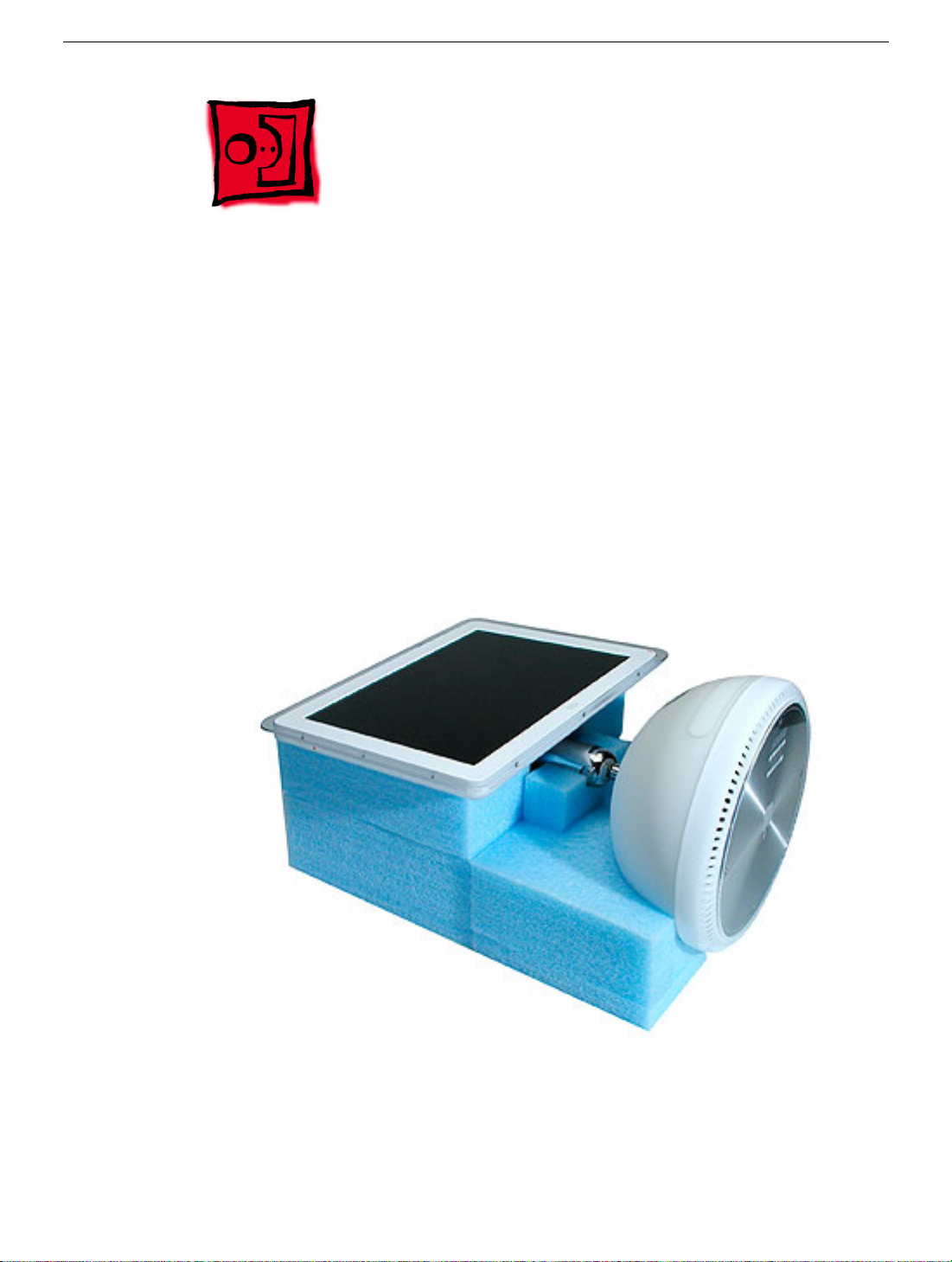
Service Stand
Tools
iMac (Flat Panel) Take Apart - 1
Page 5
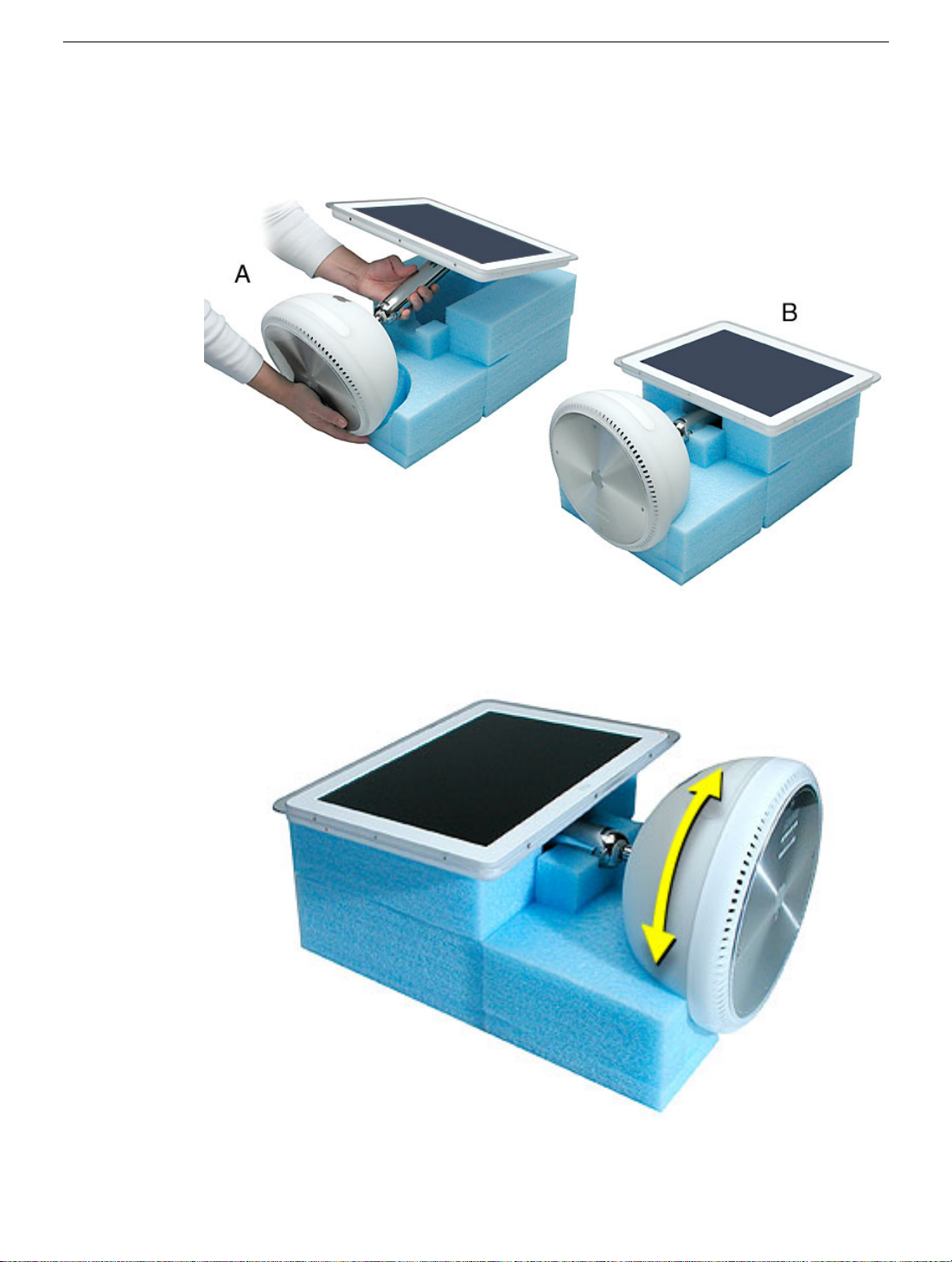
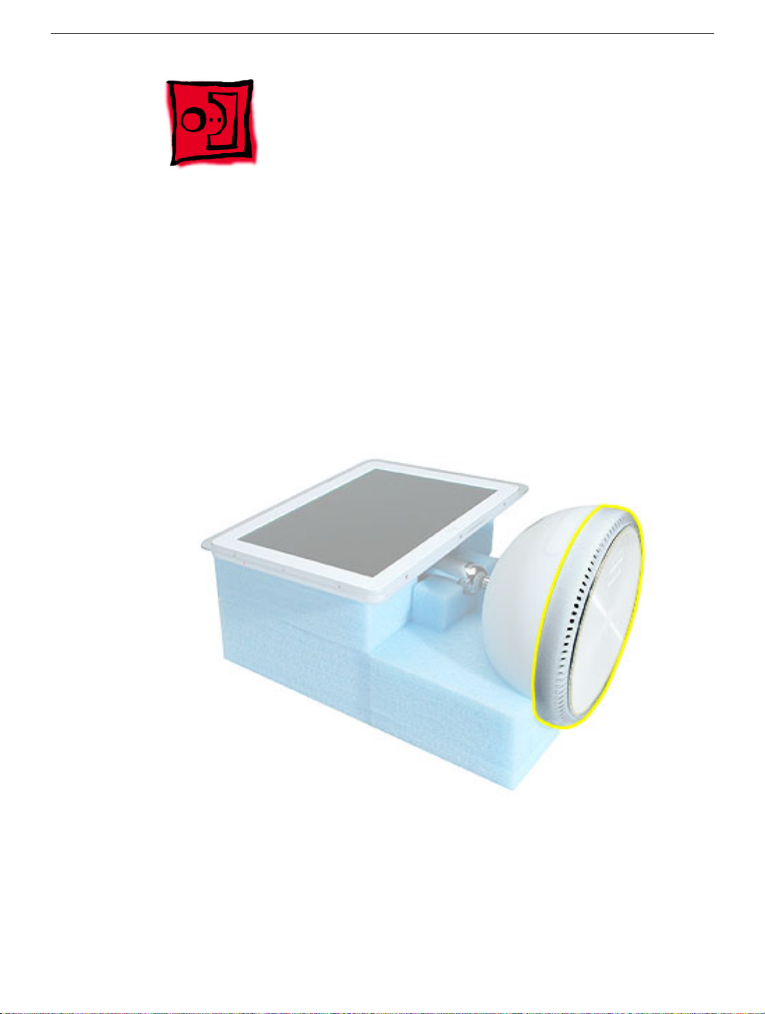
1. Support the computer by neck and the base (A). Gently position the computer in the
service stand with the flat panel facing up (B).
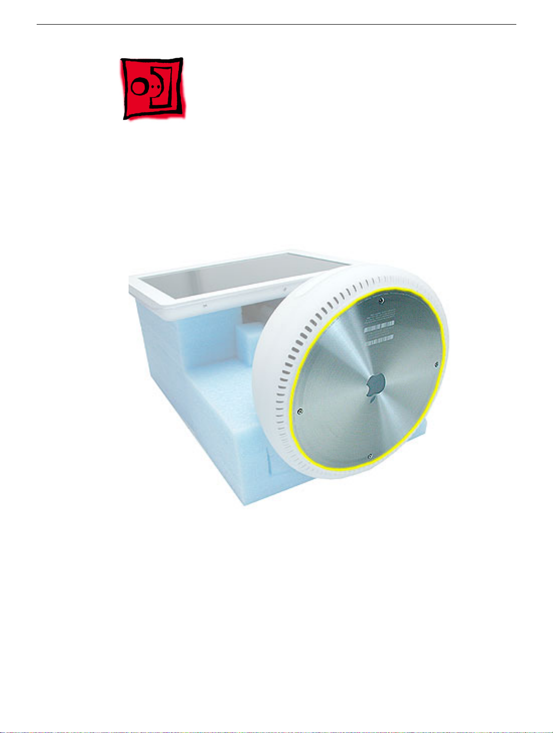
2. Note: The base of the computer can be rotated when servicing internal parts.
2 iMac (Flat Panel) Take Apart
Tools
Page 6
User Access Plate
Tools
This procedure requires the following tools:
• Phillips #0 screwdriver
Part Location
User Access Plate
Preliminary Steps
Before you begin, do the following:
• Position the computer in the service stand.
iMac (Flat Panel) Take Apart - 3
Page 7
Procedure
1. Loosen the four captive screws on the access panel.
2. Remove the panel by grabbing onto two captive screws and lift the panel off the base.
4 iMac (Flat Panel) Take Apart
User Access Plate
Page 8
AirPort Card
Tools
This procedure requires no tools.
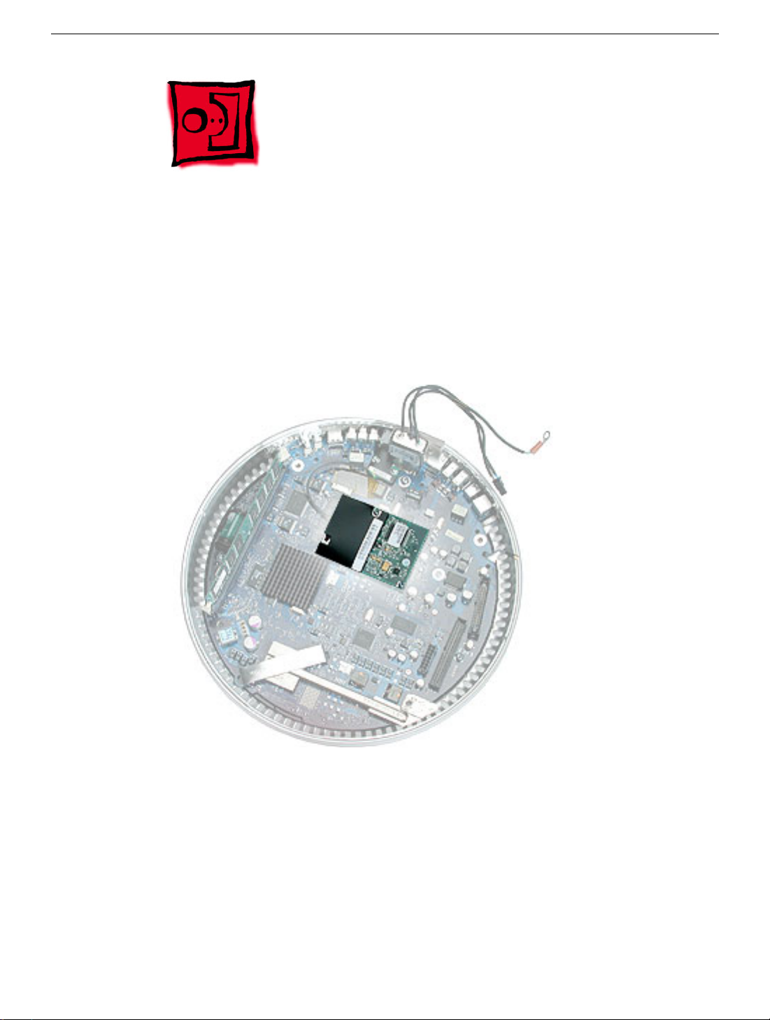
Part Location
AirPort Card
Preliminary Steps
Before you begin, do the following:
• Position the computer in the service stand.
• Remove the user access plate.
iMac (Flat Panel) Take Apart - 5
Page 9
Procedure
1. Unplug all cables from the computer except the power cord.
2. Important: To avoid electrostatic discharge, always ground yourself by touching
metal before you touch any parts or install any components inside the computer. To
avoid static electricity building back up in your body, do not walk around the room until
you have completed the installation and closed the computer.
3. Touch a metal surface inside the computer to ground yourself.
4. Unplug the power cord.
5. Disconnect the AirPort antenna and pull the plastic tab to remove the card from the
slot.
6 iMac (Flat Panel) Take Apart
AirPort Card
Page 10
Memory, SO-DIMM (userinstallable)
Tools
No tools are required for this procedure.
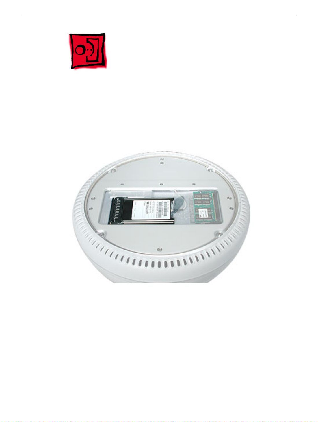
Part Location
Note: The user-installable memory slot is identified as Slot J12 by Apple Hardware Test
and Apple System Profiler.
Preliminary Steps
Before you begin, do the following:
• Position the computer in the service stand.
• Remove the user access plate.
Note: There are two RAM expansion slots on the computer. One slot (top of the logic
board) accepts the factory-installed standard PC-133 168-pin DIMM. The other slot
(bottom of logic board) accepts a standard PC-133 144-pin SO-DIMM and is accessible
on the bottom of the computer. Only the SO-DIMM slot is accessible by the user.
Memory, SO-DIMM (user-installable)
iMac (Flat Panel) Take Apart - 7
Page 11
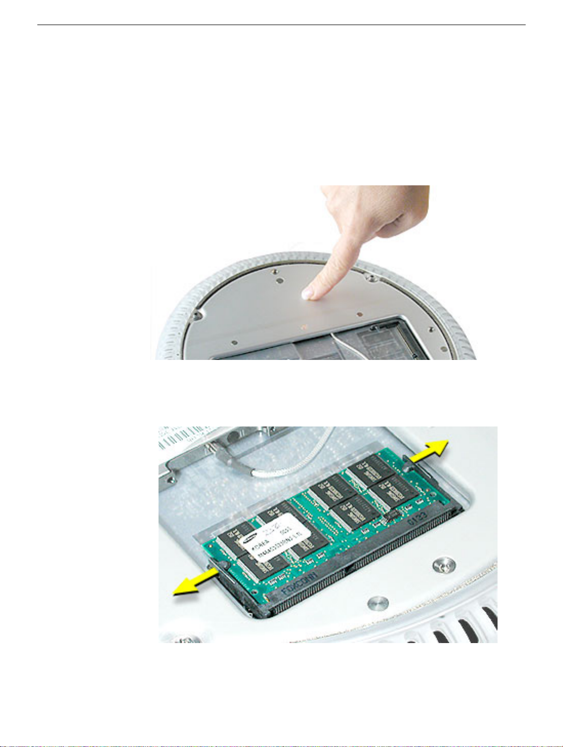
Procedure
1. Unplug all cables from the computer except the power cord.
2. Important: To avoid electrostatic discharge, always ground yourself by touching
metal before you touch any parts or install any components inside the computer. To
avoid static electricity building back up in your body, do not walk around the room until
you have completed the installation and closed the computer.
3. Touch a metal surface inside the computer to ground yourself.
4. Unplug the power cord.
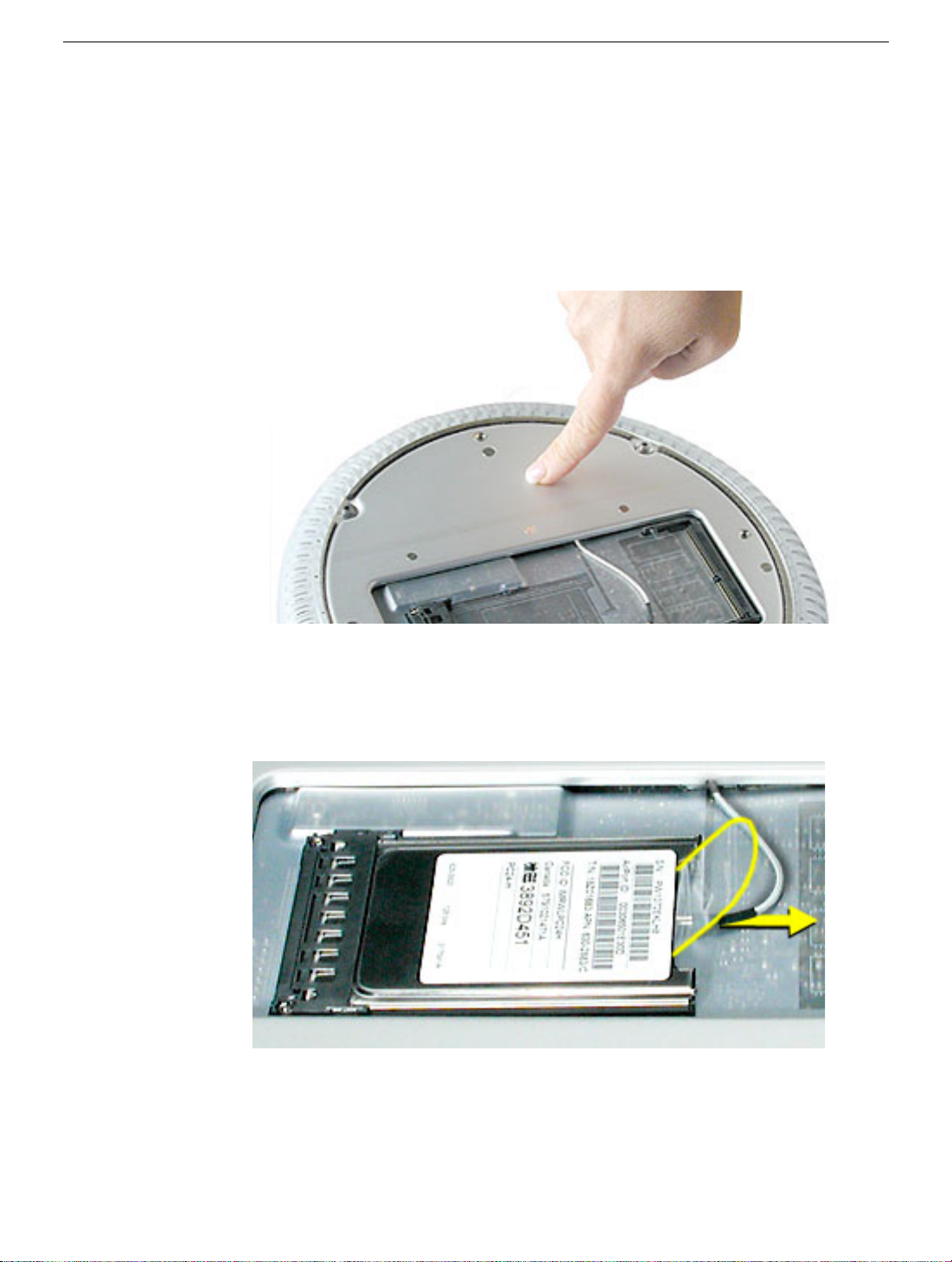
5. Push the tabs outward to release the memory.
8 iMac (Flat Panel) Take Apart
Memory, SO-DIMM (user-installable)
Page 12
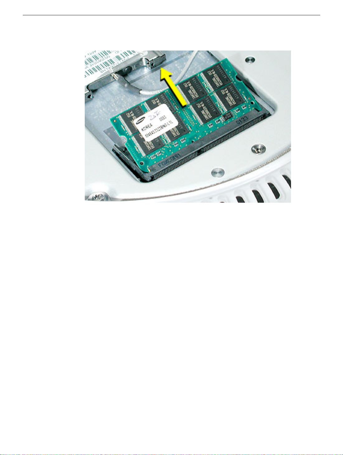
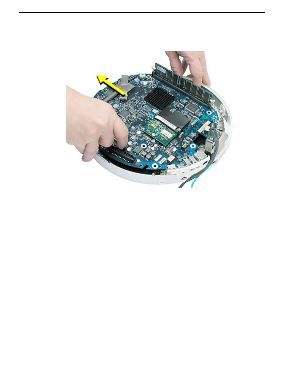
6. Remove the memory from the slot.
Memory, SO-DIMM (user-installable)
iMac (Flat Panel) Take Apart - 9
Page 13
Bottom Housing
Tools
This procedure requires the following tools:
• Torx-15 screwdriver
Part Location
Preliminary Steps
Before you begin, do the following:
• Position the computer in the service stand.
• Remove the user access plate.
10 iMac (Flat Panel) Take Apart
Bottom Housing
Page 14
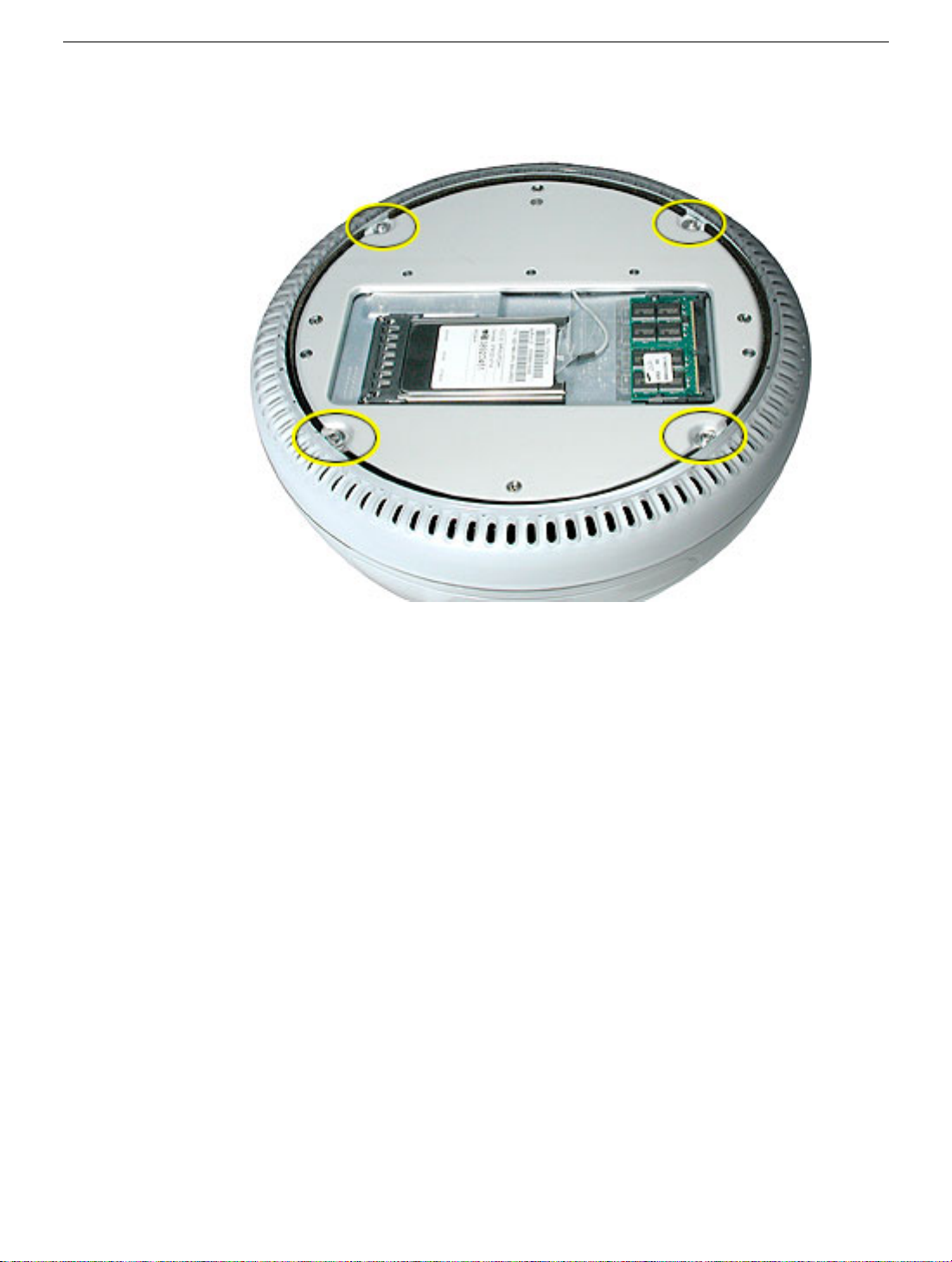
Procedure
1. Remove the four torx screws.
Replacement Note:
you do not have a torque driver, you will have to make sure these screws are
tightened by hand FIRMLY, BUT NOT FORCIBLY. Or, purchase the service tool
(076-0899) in order to ensure the thermal pipe is firmly mated with the top
base. If the bottom housing is not securely attached to the base in this fashion, the
CPU may overheat and become damaged.
Application’” in this chapter.Rotate the base so that the optical drive door is on the right.
These torx screws must be tightened to at least 17 in.-lbs. If
For more information, refer to “Thermal Paste
iMac (Flat Panel) Take Apart - 11
Page 15
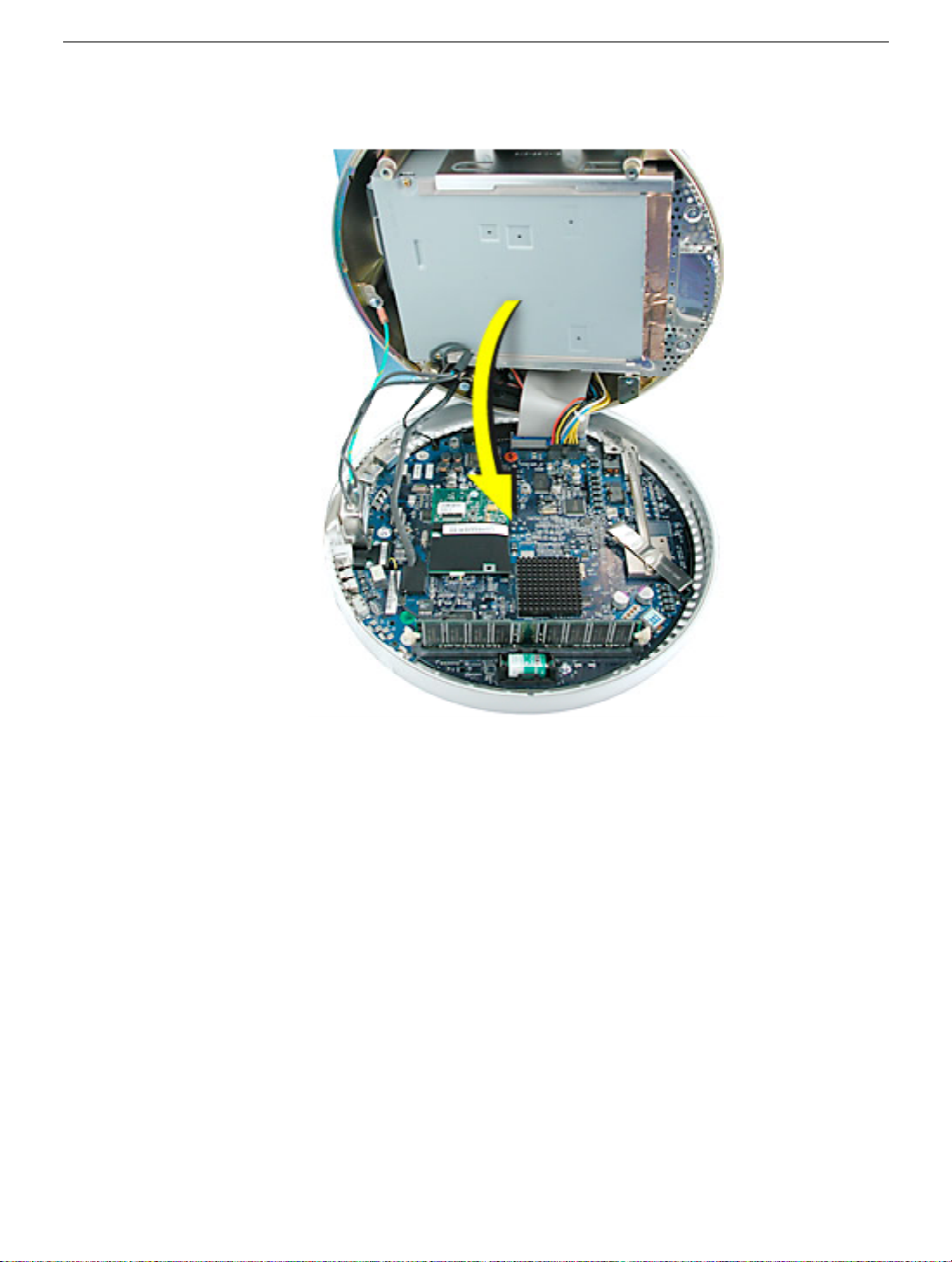
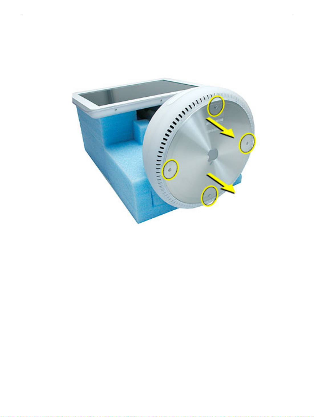
2. Rotate the base so the optical drive door is on the right. Gently open the bottom
housing in the direction of the arrow. Note: Cables are still attached to the logic board.
Important: Diagnostic service cables allow the unit to run while the bottom housing is
open (as shown above). However, the computer cannot run for more than five minutes with
the bottom housing open. If it is open longer, the CPU may overheat and become
damaged.
12 iMac (Flat Panel) Take Apart
Page 16
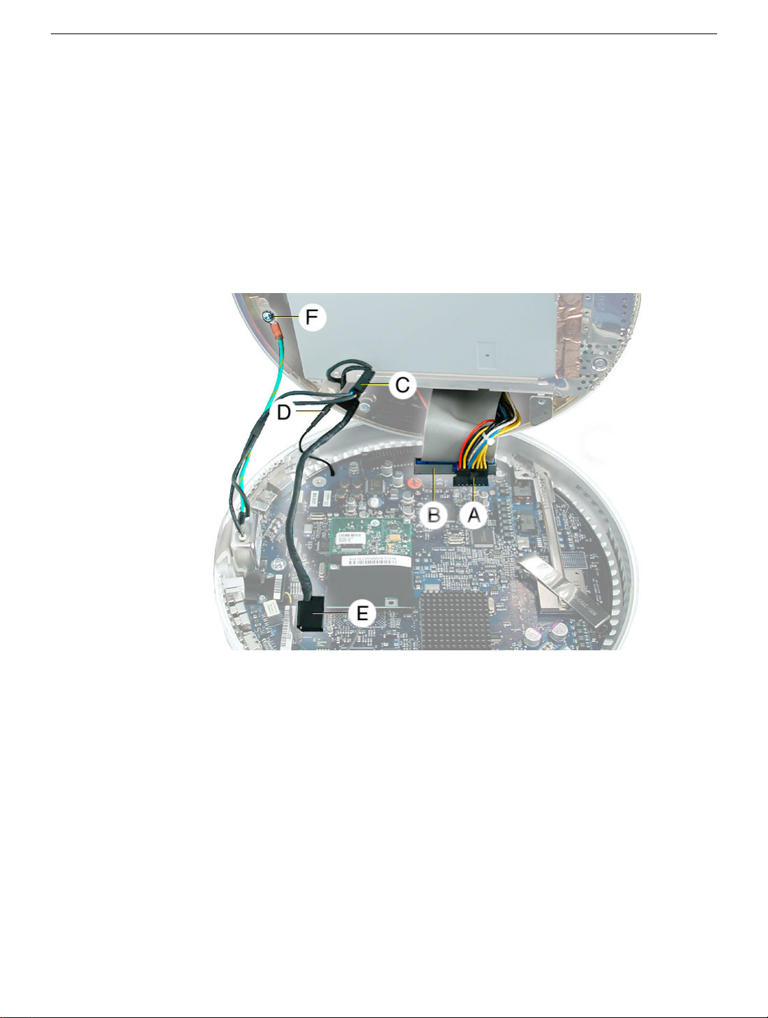
3. Disconnect the following:
Power supply connector
A
B
Hard drive/optical drive data cable
C AC line filter connector
D AirPort antenna connector
E Plastic cable retainer and video cable
F Grounding screw
Note: View the document at a larger size to enlarge this graphic.
4. Set the bottom housing aside.
Warning: Whenever the bottom housing is opened for service, you must do two things:
1.You must clean the original thermal film from the surfaces joining the thermal
interface layer and reapply thermal paste to the thermal pipe.
2.You must tighten the four torx screws on the bottom housing to a minimum of
17
in.-lbs. If you do not have a torque driver, you will have to make sure these
screws are tightened by hand FIRMLY, BUT NOT FORCIBLY. Or, purchase the
service tool (076-0899) in order to ensure the thermal pipe is firmly
mated with the top base. If the bottom housing is not securely attached to the
base in this fashion, the CPU may overheat and become damaged.
follow either of these steps could cause the computer to overheat and damage
internal components.
Refer to the topic, “Thermal Paste Application” for detailed information.
iMac (Flat Panel) Take Apart - 13
Failure to
Page 17
Thermal Paste Application
Tools
This procedure requires the following tools:
• Plastic stylus or plastic spatula to remove the old thermal paste
• Plastic stylus or plastic spatula to spread the thermal paste
• Thermal paste (922-4757)
Part Location
14 iMac (Flat Panel) Take Apart
Thermal Paste Application
Page 18

Procedure
1. Thoroughly clean the original thermal film from the mating surfaces (circled below) of
the bottom housing and thermal pipe. Use a plastic stylus to scrape the surfaces
clean. Note: Do not use an abrasive material or liquid cleaner.
2. Squeeze a thin film of thermal paste onto the thermal pipe. Spread the paste evenly.
3. Replace the bottom housing. Warning:
that must be tightened to at least 17 in.-lbs. If you do not have a torque
driver, you will have to make sure these screws are tightened by hand
FIRMLY, BUT NOT FORCIBLY. Or, purchase the service tool (076-0899) in
order to ensure the thermal pipe is firmly mated with the top base. If the
bottom housing is not securely attached to the base in this fashion, the CPU
may overheat and become damaged.
Important: Diagnostic service cables allow the unit to run while the bottom housing is
open (as shown above). However, the computer cannot run for more than five minutes with
the bottom housing open. If it is open longer, the CPU may overheat and become
damaged.
Thermal Paste Application
The bottom housing has four torx screws
iMac (Flat Panel) Take Apart - 15
Page 19

RJ-11 Modem Filter Board
Tools
This procedure requires the following tools:
• Torx-6 screwdriver
Part Location
Preliminary Steps
Before you begin, do the following:
• Position the computer in the service stand.
• Remove the user access plate.
• Remove the bottom housing.
16 iMac (Flat Panel) Take Apart
RJ-11 Modem Filter Board
Page 20
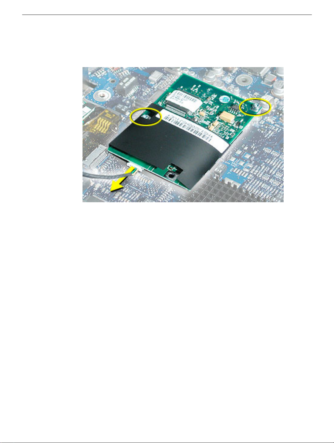
Procedure
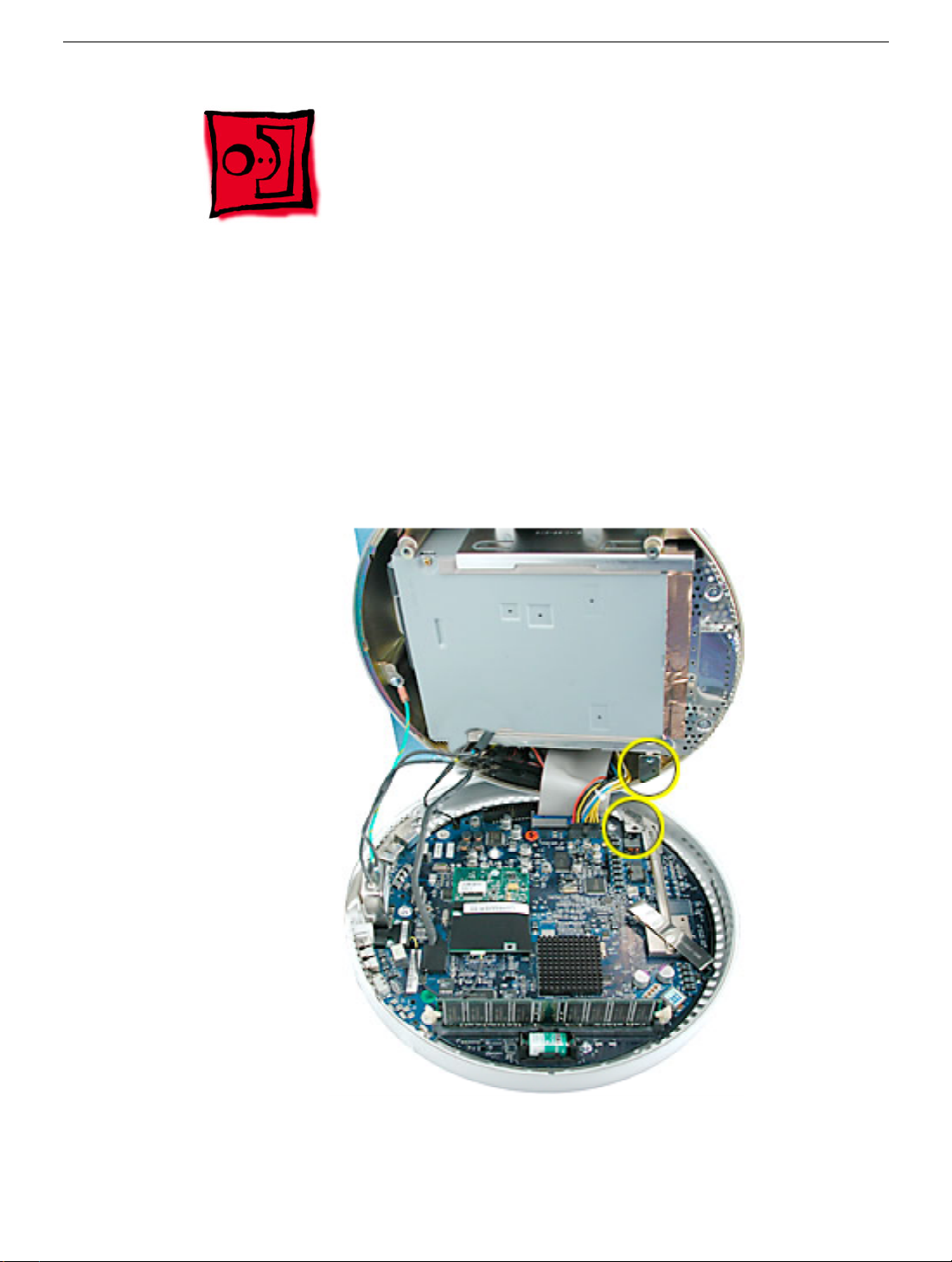
1. Remove two screws and disconnect the cable from the modem.
2. Remove the RJ-11 board from the I/O port.
Warning: Whenever the bottom housing is opened for service, you must do two things:
1. You must clean the original thermal film from the surfaces joining the thermal
interface layer and reapply thermal paste to the thermal pipe.
2. You must tighten the four torx screws on the bottom housing to a minimum of
17
in.-lbs. If you do not have a torque driver, you will have to make sure these
screws are tightened by hand FIRMLY, BUT NOT FORCIBLY. Or, purchase the
service tool (076-0899) in order to ensure the thermal pipe is firmly
mated with the top base. If the bottom housing is not securely attached to the
base in this fashion, the CPU may overheat and become damaged.
follow either of these steps could cause the computer to overheat and damage
internal components.
Refer to the topic, “Thermal Paste Application” for detailed information.
Failure to
RJ-11 Modem Filter Board
iMac (Flat Panel) Take Apart - 17
Page 21
Modem
Tools
This procedure requires the following tools:
• Torx-8 screwdriver
Part Location
Preliminary Steps
Before you begin, do the following:
• Position the computer in the service stand.
• Remove the user access plate.
• Remove the bottom housing.
18 iMac (Flat Panel) Take Apart
RJ-11 Modem Filter Board
Page 22
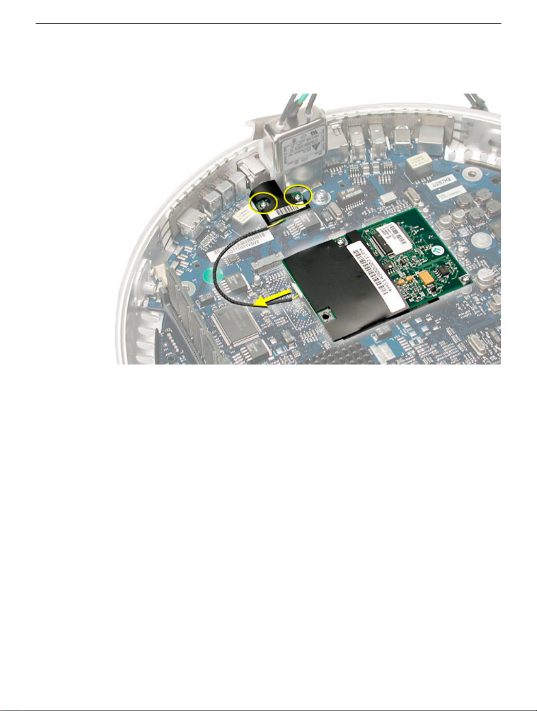
Procedure
1. Remove two screws and disconnect the cable.
2. Lift the modem from the connector on the logic board.
Warning: Whenever the bottom housing is opened for service, you must do two things:
1. You must clean the original thermal film from the surfaces joining the thermal
interface layer and reapply thermal paste to the thermal pipe.
2.You must tighten the four torx screws on the bottom housing to a minimum of
17
in.-lbs. If you do not have a torque driver, you will have to make sure these
screws are tightened by hand FIRMLY, BUT NOT FORCIBLY. Or, purchase the
service tool (076-0899) in order to ensure the thermal pipe is firmly
mated with the top base. If the bottom housing is not securely attached to the
base in this fashion, the CPU may overheat and become damaged.
follow either of these steps could cause the computer to overheat and damage
internal components.
Refer to the topic, “Thermal Paste Application” for detailed information.
Failure to
RJ-11 Modem Filter Board
iMac (Flat Panel) Take Apart - 19
Page 23
Memory (factory-installed)
Tools
This procedure requires the following tools:
• No tools are required
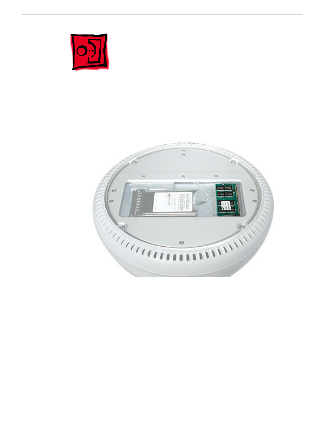
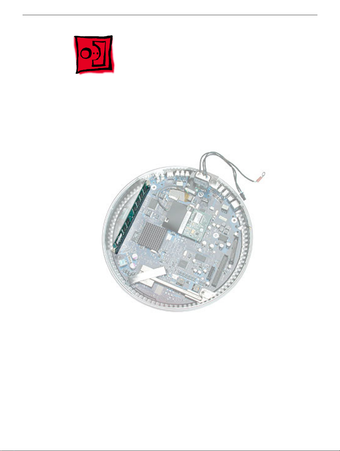
Part Location
Note: The factory-installed memory slot is identified as Slot J13 by Apple Hardware Test
and Apple System Profiler.
Preliminary Steps
Before you begin, do the following:
• Position the computer in the service stand.
• Remove the user access plate.
• Remove the bottom housing.
20 iMac (Flat Panel) Take Apart
Memory (factory-installed)
Page 24
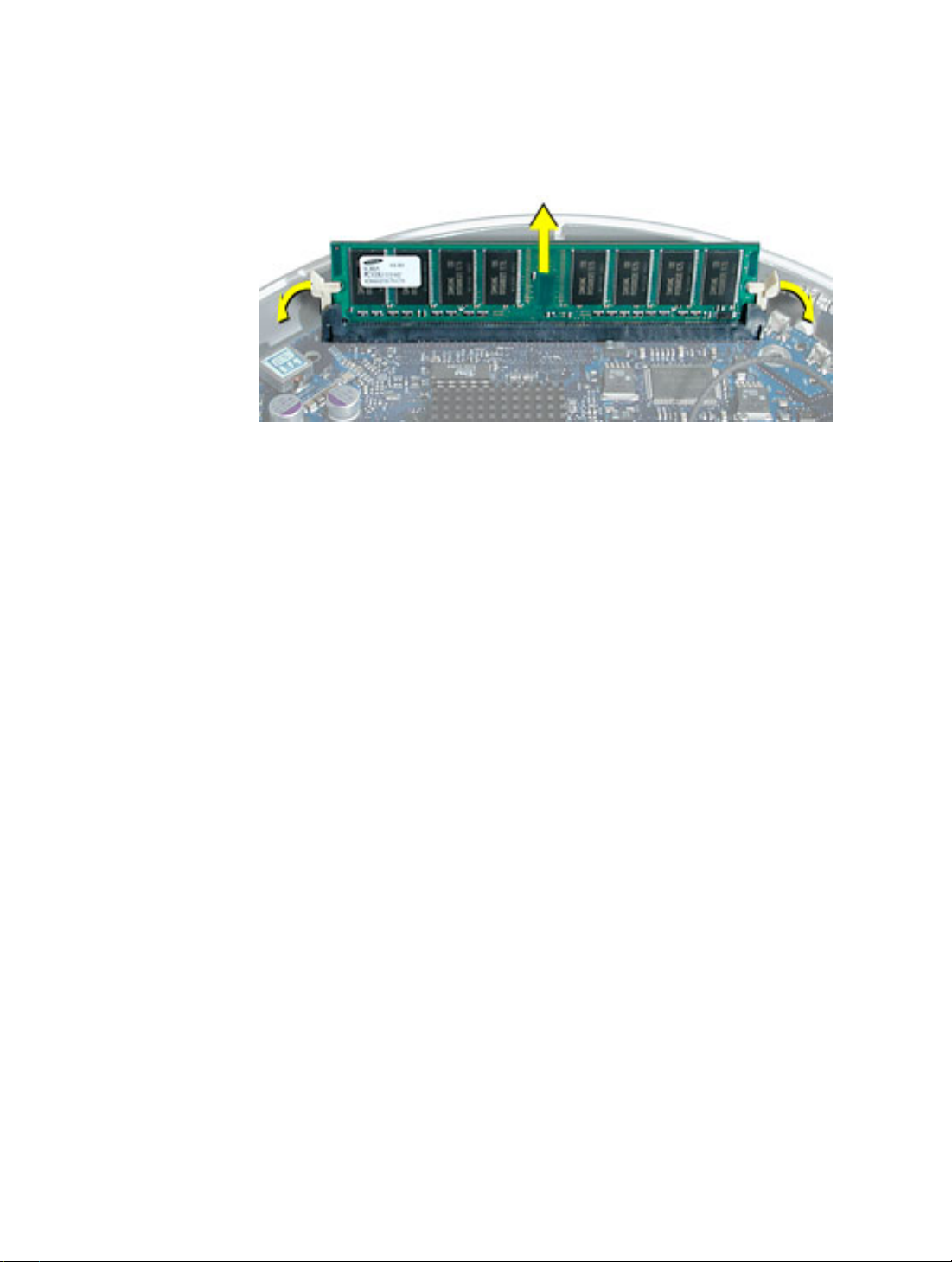
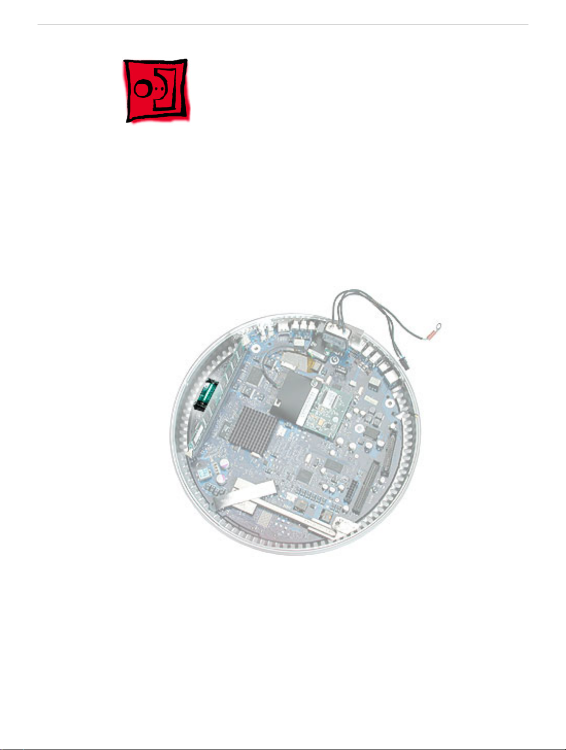
Procedure
1. Push down on the ejector tabs to release the memory module.
2. Pull the memory up and out of the slot.
Warning: Whenever the bottom housing is opened for service, you must do two things:
1. You must clean the original thermal film from the surfaces joining the thermal
interface layer and reapply thermal paste to the thermal pipe.
2.You must tighten the four torx screws on the bottom housing to a minimum of 17
in.-lbs. If you do not have a torque driver, you will have to make sure these screws
are tightened by hand FIRMLY, BUT NOT FORCIBLY. Or, purchase the service tool
(076-0899) in order to ensure the thermal pipe is firmly mated with the top base. If the
bottom housing is not securely attached to the base in this fashion, the CPU may
overheat and become damaged. Failure to follow either of these steps could cause
the computer to overheat and damage internal components.
Refer to the topic, “Thermal Paste Application” for detailed information.
Memory (factory-installed)
iMac (Flat Panel) Take Apart - 21
Page 25
Battery
Tools
This procedure requires the following tools:
• No tools are required
Part Location
Preliminary Steps
Before you begin, do the following:
• Position the computer in the service stand.
• Remove the user access plate.
• Remove the bottom housing.
22 iMac (Flat Panel) Take Apart
Battery
Page 26
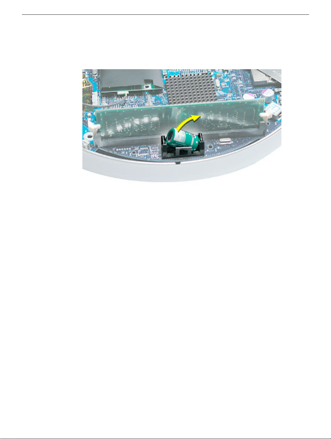
Procedure
1. Using a flatblade screwdriver, gently pry the battery from the battery holder.
Warning: Whenever the bottom housing is opened for service, you must do two things:
1. You must clean the original thermal film from the surfaces joining the thermal
interface layer and reapply thermal paste to the thermal pipe.
2.You must tighten the four torx screws on the bottom housing to a minimum of
17
in.-lbs. If you do not have a torque driver, you will have to make sure these
screws are tightened by hand FIRMLY, BUT NOT FORCIBLY. Or, purchase the
service tool (076-0899) in order to ensure the thermal pipe is firmly
mated with the top base. If the bottom housing is not securely attached to the
base in this fashion, the CPU may overheat and become damaged.
follow either of these steps could cause the computer to overheat and damage
internal components.
Refer to the topic, “Thermal Paste Application” for detailed information.
Failure to
Battery
iMac (Flat Panel) Take Apart - 23
Page 27
Logic Board
Tools
This procedure requires the following tools:
• Phillips #2 screwdriver (for the plastic screw)
• Torx-15 screwdriver
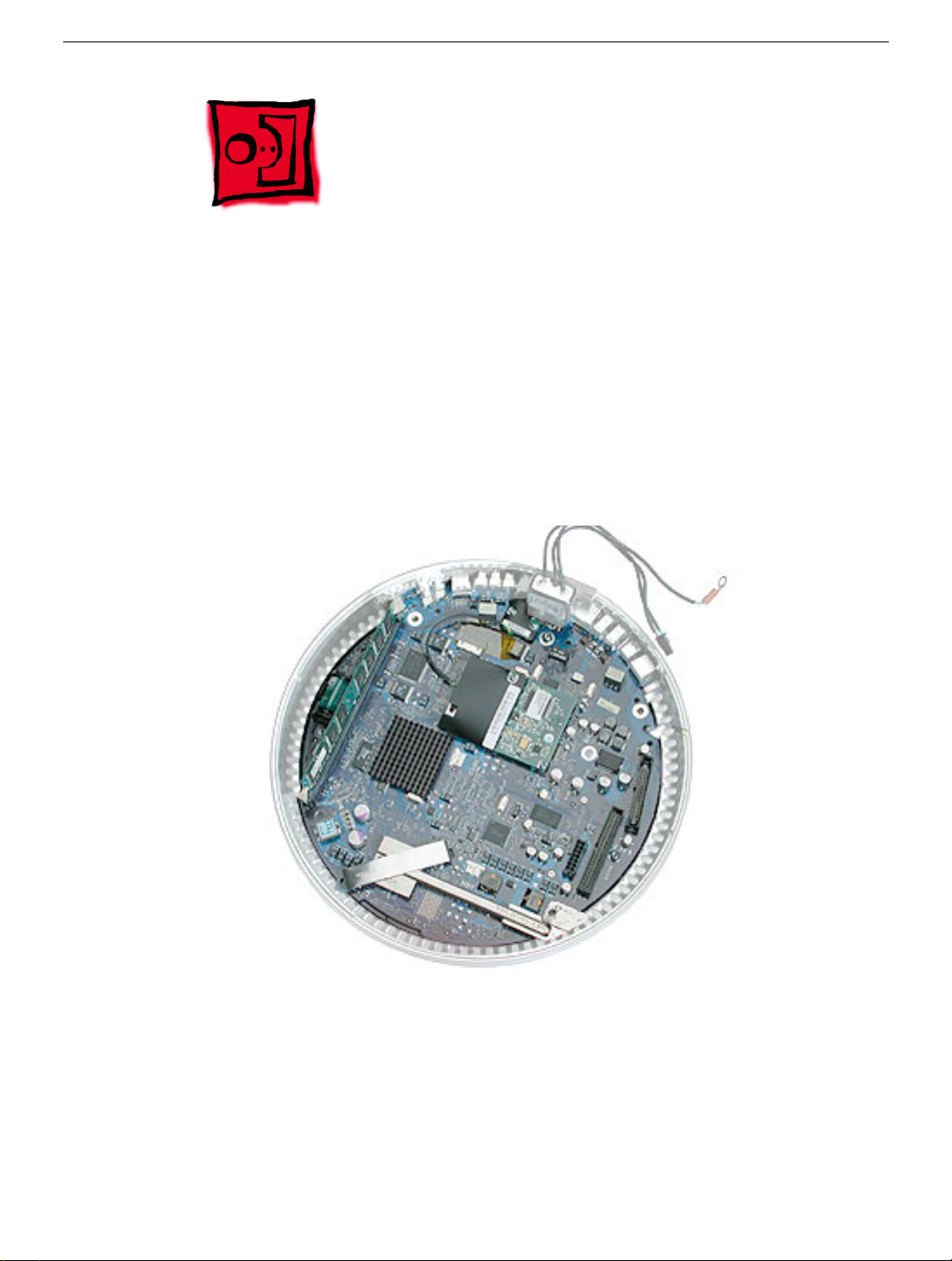
Part Location
Note: The battery, RJ-11 board, AirPort card, modem, I/O port covers, and memory (on
the top and the bottom of the logic board) need to be removed from the logic board before
returning the board to Apple for service.
Preliminary Steps
Before you begin, do the following:
• Position the computer in the service stand.
• Remove the user access plate.
• Remove the bottom housing.
• Remove the RJ-11 board.
24 iMac (Flat Panel) Take Apart
Logic Board
Page 28
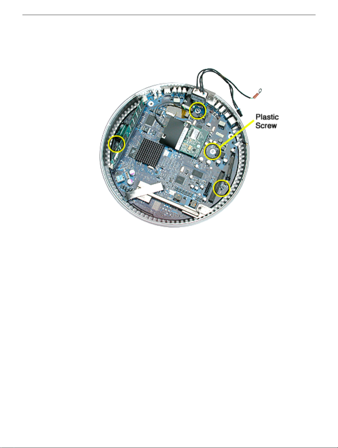
Procedure
1. Remove the three metal torx screws and the one plastic screw.
Logic Board
iMac (Flat Panel) Take Apart - 25
Page 29
2. Grab the logic board by the battery retainer and the hard drive connector. Lift the
board and pull back to release the board from the bottom housing and I/O ports. Note:
The I/O port covers may come out with the logic board when it’s removed.
3. Remove the I/O port covers from the logic board.
Warning: Whenever the bottom housing is opened for service, you must do two things:
1.You must clean the original thermal film from the surfaces joining the thermal
interface layer and reapply thermal paste to the thermal pipe.
2. You must tighten the four torx screws on the bottom housing to a minimum of
17
in.-lbs. If you do not have a torque driver, you will have to make sure these
screws are tightened by hand FIRMLY, BUT NOT FORCIBLY. Or, purchase the
service tool (076-0899) in order to ensure the thermal pipe is firmly
mated with the top base. If the bottom housing is not securely attached to the
base in this fashion, the CPU may overheat and become damaged.
follow either of these steps could cause the computer to overheat and damage
internal components.
Refer to the topic, “Thermal Paste Application” for detailed information.
Warning: Whenever the logic board is separated from the bottom housing, you must
install new thermal pads to three surfaces on the bottom housing. The thermal pads help
cool components on the logic board. Failure to apply these pads whenever the logic board
Failure to
26 iMac (Flat Panel) Take Apart
Logic Board
Page 30

is separated from the bottom housing could cause these parts to overheat. Short term
separation, where the thermal pads are not handled excessively
if you are simply testing the logic board and only detach it for a few minutes)
does not require replacement. Refer to “Thermal Pad Installation” in this chapter for
detailed information.
Important: Diagnostic service cables allow the unit to run while the bottom housing is
open (as shown above). However, the computer cannot run for more than five minutes with
the bottom housing open. If it is open longer, the CPU may overheat and become
damaged.
(an exception would be
,
Logic Board
iMac (Flat Panel) Take Apart - 27
Page 31

I/O Port Covers
Tools
This procedure requires the following tools:
• No tools are required
Part Location
Preliminary Steps
Before you begin, do the following:
• Position the computer in the service stand.
• Remove the user access plate.
• Remove the bottom housing.
• Remove the RJ-11 board
• Remove the logic board.
28 iMac (Flat Panel) Take Apart
I/O Port Covers
Page 32

Procedure
1. Gently remove the I/O port covers from the logic board.
Warning: Whenever the bottom housing is opened for service, you must do two things:
1.You must clean the original thermal film from the surfaces joining the thermal
interface layer and reapply thermal paste to the thermal pipe.
2. You must tighten the four torx screws on the bottom housing to a minimum of
17
in.-lbs. If you do not have a torque driver, you will have to make sure these
screws are tightened by hand FIRMLY, BUT NOT FORCIBLY. Or, purchase the
service tool (076-0899) in order to ensure the thermal pipe is firmly
mated with the top base. If the bottom housing is not securely attached to the
base in this fashion, the CPU may overheat and become damaged.
follow either of these steps could cause the computer to overheat and damage
internal components.
Refer to the topic, “Thermal Paste Application” for detailed information.
Failure to
I/O Port Covers
iMac (Flat Panel) Take Apart - 29
Page 33

Thermal Pad Installation
Tools
• No tools are required.
• Thermal pad kit
Part Location
Warning: Whenever the logic board is removed, you must install new thermal pads to
three surfaces (shown above). Failure to apply these pads could cause the computer to
overheat and possibly damage the internal components. Note:
you are simply testing the logic board and only detach it for a few minutes
30 iMac (Flat Panel) Take Apart
An exception would be if
.
Thermal Pad Installation
Page 34

Procedure
1. Remove the old thermal pads (shown below) from the bottom housing. Note: If you
don’t see all three thermal pads on the bottom housing, check the bottom side of the
logic board. The thermal pads may stick to the logic board. Either way, remove the old
thermal pads.
2. Using the thermal pad kit, remove the clear protective backing from the new thermal
pads.
3. Place the new thermal pads on the bottom housing. Press down on the blue protective
backing to make sure the thermal pad has even contact with the bottom housing.
There should be no air pockets.
4. Remove the blue protective backing from the new thermal pad. Note: Avoid
unnecessary contact with either side of the thermal pad as dirt and body oils reduce
the thermal pad's conductivity.
5. Holding the logic board by the battery retainer and the internal drive cable connector,
slide the logic board back into the bottom housing (make sure the I/O port covers are
on the logic board). Important: Do not push on the heatsink for leverage, as you could
knock it off the chip.
Thermal Pad Installation
iMac (Flat Panel) Take Apart - 31
Page 35

AC Line Filter
Tools
This procedure requires the following tools:
• Torx-10 screwdriver
Part Location
Preliminary Steps
Before you begin, do the following:
• Position the computer in the service stand.
• Remove the user access plate.
• Remove the bottom housing.
• Remove the RJ-11 board.
• Remove the logic board.
32 iMac (Flat Panel) Take Apart
AC Line Filter
Page 36

Procedure
1. Peel back the black insulator on the bottom housing to access the AC line filter
screws.
2. Remove two screws and lift the AC line filter from the bottom housing. Note: The AC
line port cover plug may fall out of the bottom housing when you remove the AC line
filter. Place the plug back into the bottom housing before reinstalling the AC line filter.
AC Line Filter
iMac (Flat Panel) Take Apart - 33
Page 37

Warning: Whenever the bottom housing is opened for service, you must do two things:
1.You must clean the original thermal film from the surfaces joining the thermal
interface layer and reapply thermal paste to the thermal pipe.
2. You must tighten the four torx screws on the bottom housing to a minimum of
17
in.-lbs. If you do not have a torque driver, you will have to make sure these
screws are tightened by hand FIRMLY, BUT NOT FORCIBLY. Or, purchase the
service tool (076-0899) in order to ensure the thermal pipe is firmly
mated with the top base. If the bottom housing is not securely attached to the
base in this fashion, the CPU may overheat and become damaged.
follow either of these steps could cause the computer to overheat and damage
internal components.
Refer to the topic, “Thermal Paste Application” for detailed information.
Warning: Whenever the logic board is separated from the bottom housing, you must
install new thermal pads to three surfaces on the bottom housing. The thermal pads help
cool components on the logic board. Failure to apply these pads whenever the logic board
is separated from the bottom housing could cause these parts to overheat. Short term
separation, where the thermal pads are not handled excessively
(an exception would be
if you are simply testing the logic board and only detach it for a few minutes)
does not require replacement.
Refer to “Thermal Pad Installation” in this chapter for detailed information.
Failure to
,
34 iMac (Flat Panel) Take Apart
AC Line Filter
Page 38

Drive Carrier Assembly (Optical and Hard Drive)
Tools
This procedure requires the following tools:
• Torx-10 screwdriver
Part Location
Preliminary Steps
Before you begin, do the following:
• Position the computer in the service stand with the door facing up.
• Remove the user access plate.
• Remove the bottom housing.
Drive Carrier Assembly (Optical and Hard Drive)
iMac (Flat Panel) Take Apart - 35
Page 39

Procedure
1. Rotate the base unit so the optical drive door is facing up (as shown below).
2. Remove two screws on the EMI shield. Carefully lift the shield and peel the copper
tape off the drive.
36 iMac (Flat Panel) Take Apart
Drive Carrier Assembly (Optical and Hard Drive)
Page 40

3. Remove four screws attaching the drive carrier to the metal chassis (also known as
the Faraday cage).
Drive Carrier Assembly (Optical and Hard Drive)
iMac (Flat Panel) Take Apart - 37
Page 41

4. With the drive door still positioned at the top, look for the white plastic clip attached to
the side of the drive carrier. Open the clip and remove the Airport antenna and the
video cable from the cable clip.
38 iMac (Flat Panel) Take Apart
Drive Carrier Assembly (Optical and Hard Drive)
Page 42

5. Grasp the carrier on both sides. Lift and pull the carrier in the direction of the arrow.
Once the carrier is out, flip the carrier to the right to disconnect the power cables.
Note: The carrier fits snugly into the chassis.
6. Disconnect the data cables.
7. Peel the white wrapper up to access the screws connecting the hard drive to the
carrier.
Drive Carrier Assembly (Optical and Hard Drive)
iMac (Flat Panel) Take Apart - 39
Page 43

8. Remove the hard drive from the carrier.
9. Remove four screws (shown by circles) to remove the optical drive from the carrier.
10. Slide the optical drive out of the carrier. Be careful of the black plastic dust filter on the
carrier. It is very fragile and can rip easily if not handled properly. Note: The silver
insulator is part of the carrier assembly.
Warning: Whenever the bottom housing is opened for service, you must do two things:
40 iMac (Flat Panel) Take Apart
Drive Carrier Assembly (Optical and Hard Drive)
Page 44

1.You must clean the original thermal film from the surfaces joining the thermal
interface layer and reapply thermal paste to the thermal pipe.
2. You must tighten the four torx screws on the bottom housing to a minimum of 17
in.-lbs. If you do not have a torque driver, you will have to make sure these screws
are tightened by hand FIRMLY, BUT NOT FORCIBLY. Or, purchase the service tool
(076-0899) in order to ensure the thermal pipe is firmly mated with the top base. If the
bottom housing is not securely attached to the base in this fashion, the CPU may
overheat and become damaged. Failure to follow either of these steps could cause
the computer to overheat and damage internal components.
Refer to the topic, “Thermal Paste Application” for detailed information.
iMac (Flat Panel) Take Apart - 41
Page 45

Power Supply
Tools
This procedure requires the following tools:
• Torx-10 screwdriver
Part Location
Preliminary Steps
Before you begin, do the following:
• Position the computer in the service stand and rotate the door to the right.
• Remove the user access plate.
• Remove the bottom housing.
• Remove the drive carrier assembly.
42 iMac (Flat Panel) Take Apart
Power Supply
Page 46

Procedure
1. Remove the two power supply screws circled below.
Power Supply
iMac (Flat Panel) Take Apart - 43
Page 47

2. Open the optical drive door as shown to locate the two hidden screws near the drive
door. Remove the four screws. Note: Support the metal plate and power supply as
you remove the screws.
Important: The two screws near the door hinge are shorter than the other power
supply screws. Failure to replace the shorter screws into their correct location will
scratch the top housing. See step 4, Replacement Note.
44 iMac (Flat Panel) Take Apart
Power Supply
Page 48

3. Remove the power supply from the chassis, keeping the two halves connected.
Power Supply
4. Replacement Note: When replacing the metal plate (see picture above) that sits on
top of the power supply, make certain that the two shorter screws are inserted into the
screw holes near the optical door. If the longer screws are inserted by mistake, the
screws will scratch the top housing (circled below).
iMac (Flat Panel) Take Apart - 45
Page 49

Warning: Whenever the bottom housing is opened for service, you must do two things:
1.You must clean the original thermal film from the surfaces joining the thermal
interface layer and reapply thermal paste to the thermal pipe.
2. You must tighten the four torx screws on the bottom housing to a minimum of 17
in.-lbs. If you do not have a torque driver, you will have to make sure these screws
are tightened by hand FIRMLY, BUT NOT FORCIBLY. Or, purchase the service tool
(076-0899) in order to ensure the thermal pipe is firmly mated with the top base. If the
bottom housing is not securely attached to the base in this fashion, the CPU may
overheat and become damaged. Failure to follow either of these steps could cause
the computer to overheat and damage internal components.
Refer to the topic, “Thermal Paste Application” for detailed information.
46 iMac (Flat Panel) Take Apart
Power Supply
Page 50

Optical Drive Door
Tools
This procedure requires the following tools:
• Torx-10 screwdriver
• Needlenose pliers
Part Location
Optical Drive Door
Preliminary Steps
Before you begin, do the following:
• Position the computer in the service stand.
• Remove the user access plate.
• Remove the bottom housing.
• Remove the drive carrier assembly.
iMac (Flat Panel) Take Apart - 47
Page 51

Procedure
1. Remove the four screws on the power supply metal shield. Set the shield aside.
Important: The two screws near the door hinge are shorter than the other power
supply screws. Failure to replace the shorter screws to their correct location will
scratch the top housing. See step 4, Replacement Note in the Power Supply section
for a picture.
48 iMac (Flat Panel) Take Apart
Optical Drive Door
Page 52

2. Slide the plastic door frame off the chassis.
3. Carefully remove the two door springs with a needlenose pliers.
Optical Drive Door
iMac (Flat Panel) Take Apart - 49
Page 53

4. Remove the door hinge screws.
5. Open the door open.
50 iMac (Flat Panel) Take Apart
Optical Drive Door
Page 54

6. Slide the door and hinge off the frame. Remove the door from the base.
Warning: Whenever the bottom housing is opened for service, you must do two things:
1.You must clean the original thermal film from the surfaces joining the thermal
interface layer and reapply thermal paste to the thermal pipe.
2. You must tighten the four torx screws on the bottom housing to a minimum of 17
in.-lbs. If you do not have a torque driver, you will have to make sure these screws
are tightened by hand FIRMLY, BUT NOT FORCIBLY. Or, purchase the service tool
(076-0899) in order to ensure the thermal pipe is firmly mated with the top base. If the
bottom housing is not securely attached to the base in this fashion, the CPU may
overheat and become damaged. Failure to follow either of these steps could cause
the computer to overheat and damage internal components.
Refer to the topic, “Thermal Paste Application” for detailed information.
Optical Drive Door
iMac (Flat Panel) Take Apart - 51
Page 55

Speaker, Internal
Tools
This procedure requires the following tools:
• Torx-10 screwdriver
Part Location
Preliminary Steps
Before you begin, do the following:
• Position the computer in the service stand.
• Remove the user access plate.
• Remove the bottom housing.
• Remove the drive carrier assembly.
52 iMac (Flat Panel) Take Apart
Speaker, Internal
Page 56

Procedure
1. Loosen the two screws enough to slide the speaker off the metal posts. Disconnect
the speaker cable.
Warning: Whenever the bottom housing is opened for service, you must do two things:
1.You must clean the original thermal film from the surfaces joining the thermal
interface layer and reapply thermal paste to the thermal pipe.
2. You must tighten the four torx screws on the bottom housing to a minimum of 17
in.-lbs. If you do not have a torque driver, you will have to make sure these screws
are tightened by hand FIRMLY, BUT NOT FORCIBLY. Or, purchase the service tool
(076-0899) in order to ensure the thermal pipe is firmly mated with the top base. If the
bottom housing is not securely attached to the base in this fashion, the CPU may
overheat and become damaged. Failure to follow either of these steps could cause
the computer to overheat and damage internal components.
Refer to the topic, “Thermal Paste Application” for detailed information.
Speaker, Internal
iMac (Flat Panel) Take Apart - 53
Page 57

Fan
Tools
This procedure requires the following tools:
• Torx-15 screwdriver
Part Location
Preliminary Steps
Before you begin, do the following:
• Position the computer in the service stand.
• Remove the user access plate.
• Remove the bottom housing.
• Remove the drive carrier assembly.
54 iMac (Flat Panel) Take Apart
Fan
Page 58

Procedure
1. Remove the two fan screws and disconnect the fan connector.
2. Lift the fan out of the chassis (Faraday cage).
Warning: Whenever the bottom housing is opened for service, you must do two things:
1.You must clean the original thermal film from the surfaces joining the thermal
interface layer and reapply thermal paste to the thermal pipe.
2. You must tighten the four torx screws on the bottom housing to a minimum of 17
in.-lbs. If you do not have a torque driver, you will have to make sure these screws
are tightened by hand FIRMLY, BUT NOT FORCIBLY. Or, purchase the service tool
(076-0899) in order to ensure the thermal pipe is firmly mated with the top base. If the
bottom housing is not securely attached to the base in this fashion, the CPU may
overheat and become damaged. Failure to follow either of these steps could cause
the computer to overheat and damage internal components.
Refer to the topic, “Thermal Paste Application” for detailed information.
Fan
iMac (Flat Panel) Take Apart - 55
Page 59

Power Supply Insulators
Tools
No tools are required for this procedure.
Part Location
Preliminary Steps
Before you begin, do the following:
• Position the computer in the service stand.
• Remove the user access plate.
• Remove the bottom housing.
• Remove the drive carrier assembly.
• Remove the power supply.
56 iMac (Flat Panel) Take Apart
Power Supply Insulators
Page 60

Procedure
1. Carefully pull the insulators from the chassis (Faraday cage). These are attached to
the chassis with double-sided tape.
Warning: Whenever the bottom housing is opened for service, you must do two things:
1.You must clean the original thermal film from the surfaces joining the thermal
interface layer and reapply thermal paste to the thermal pipe.
2. You must tighten the four torx screws on the bottom housing to a minimum of 17
in.-lbs. If you do not have a torque driver, you will have to make sure these screws
are tightened by hand FIRMLY, BUT NOT FORCIBLY. Or, purchase the service tool
(076-0899) in order to ensure the thermal pipe is firmly mated with the top base. If the
bottom housing is not securely attached to the base in this fashion, the CPU may
overheat and become damaged. Failure to follow either of these steps could cause
the computer to overheat and damage internal components.
Refer to the topic, “Thermal Paste Application” for detailed information.
Power Supply Insulators
iMac (Flat Panel) Take Apart - 57
Page 61

Neck Cable Retainer (under fan)
Tools
This procedure requires the following tools:
• Torx-10 screwdriver
Part Location
Note: View the document at a larger size to enlarge this graphic.
Preliminary Steps
Before you begin, do the following:
• Position the computer in the service stand.
• Remove the user access plate.
• Remove the bottom housing.
• Remove the drive carrier assembly.
• Remove the power supply.
• Remove the fan.
58 iMac (Flat Panel) Take Apart
Neck Cable Retainer (under fan)
Page 62

Procedure
1. WIth the optical door oriented upward, remove the four screws connecting the plastic
cable retainer to the chassis (Faraday cage).
Note: View the document at a larger size to enlarge this graphic.
2. Lift the plastic cable retainer from the chassis. Note: The fan gasket is stuck to the
back side of the plastic cable retainer.
Warning: Whenever the bottom housing is opened for service, you must do two things:
1.You must clean the original thermal film from the surfaces joining the thermal
interface layer and reapply thermal paste to the thermal pipe.
2. You must tighten the four torx screws on the bottom housing to a minimum of 17
in.-lbs. If you do not have a torque driver, you will have to make sure these screws
are tightened by hand FIRMLY, BUT NOT FORCIBLY. Or, purchase the service tool
(076-0899) in order to ensure the thermal pipe is firmly mated with the top base. If the
bottom housing is not securely attached to the base in this fashion, the CPU may
overheat and become damaged. Failure to follow either of these steps could cause
the computer to overheat and damage internal components.
Refer to the topic, “Thermal Paste Application” for detailed information.
Neck Cable Retainer (under fan)
iMac (Flat Panel) Take Apart - 59
Page 63

Fan Gasket
Tools
No tools are required for this procedure.
Part Location
Preliminary Steps
Before you begin, do the following:
• Position the computer in the service stand.
• Remove the user access plate.
• Remove the bottom housing.
• Remove the drive carrier assembly.
• Remove the power supply.
• Remove the fan.
• Remove the plastic cable retainer.
60 iMac (Flat Panel) Take Apart
Fan Gasket
Page 64

Procedure
1. Remove the plastic cable retainer and turn it over. Gently peel the fan gasket off the
back of the cable retainer.
Warning: Whenever the bottom housing is opened for service, you must do two things:
1.You must clean the original thermal film from the surfaces joining the thermal
interface layer and reapply thermal paste to the thermal pipe.
2. You must tighten the four torx screws on the bottom housing to a minimum of 17
in.-lbs. If you do not have a torque driver, you will have to make sure these screws
are tightened by hand FIRMLY, BUT NOT FORCIBLY. Or, purchase the service tool
(076-0899) in order to ensure the thermal pipe is firmly mated with the top base. If the
bottom housing is not securely attached to the base in this fashion, the CPU may
overheat and become damaged. Failure to follow either of these steps could cause
the computer to overheat and damage internal components.
Refer to the topic, “Thermal Paste Application” for detailed information.
Fan Gasket
iMac (Flat Panel) Take Apart - 61
Page 65

Cap, Neck Spoke Retainer
Tools
This procedure requires the following tools:
• Torx-10 screwdriver
Part Location
Preliminary Steps
Before you begin, do the following:
• Position the computer in the service stand.
• Remove the user access plate.
• Remove the bottom housing.
• Remove the drive carrier assembly.
• Remove the power supply.
• Remove the fan.
• Remove the plastic cable retainer.
62 iMac (Flat Panel) Take Apart
Cap, Neck Spoke Retainer
Page 66

Procedure
1. The neck cables are highlighted below. Note the cable routing, including the blind
mate connector orientation before removing the cap screws and neck cap.
Note: View the document at a larger size to enlarge the next two graphics.
2. Loosen the three silver screws (circled below) to remove the neck cap. Lift the cap off
the spokes. Note: The two black screws keep the neck attached to the base.
Cap, Neck Spoke Retainer
iMac (Flat Panel) Take Apart - 63
Page 67

Warning: Whenever the bottom housing is opened for service, you must do two things:
1.You must clean the original thermal film from the surfaces joining the thermal
interface layer and reapply thermal paste to the thermal pipe.
2. You must tighten the four torx screws on the bottom housing to a minimum of 17
in.-lbs. If you do not have a torque driver, you will have to make sure these screws
are tightened by hand FIRMLY, BUT NOT FORCIBLY. Or, purchase the service tool
(076-0899) in order to ensure the thermal pipe is firmly mated with the top base. If the
bottom housing is not securely attached to the base in this fashion, the CPU may
overheat and become damaged. Failure to follow either of these steps could cause
the computer to overheat and damage internal components.
Refer to the topic, “Thermal Paste Application” for detailed information.
64 iMac (Flat Panel) Take Apart
Cap, Neck Spoke Retainer
Page 68

Blind Mate Connector
Tools
This procedure requires the following tools:
• Torx-10 screwdriver
Part Location
Preliminary Steps
Before you begin, do the following:
• Position the computer in the service stand.
• Remove the user access plate.
• Remove the bottom housing.
• Remove the drive carrier assembly.
• Remove the power supply.
• Remove the fan.
• Remove the plastic cable retainer.
• Remove the cap neck spoke retainer.
Blind Mate Connector
iMac (Flat Panel) Take Apart - 65
Page 69

Procedure
1. Remove the two blind mate screws. Replacement Note: The tab on the blind mate
connector faces inward.
2. Lift the blind mate connector off the chassis. Note: The blind mate connector is part of
the neck assembly.
Replacement Notes:
Blind Mate Connector: Make sure to replace the blind mate connector into the chassis
with the tab facing inward (toward the fan). And, when tightening the screws, the blind
mate connector should have some play; do not tighten down so it doesn’t move at all.
Warning: Whenever the bottom housing is opened for service, you must do two things:
1.You must clean the original thermal film from the surfaces joining the thermal
interface layer and reapply thermal paste to the thermal pipe.
2. You must tighten the four torx screws on the bottom housing to a minimum of 17
in.-lbs. If you do not have a torque driver, you will have to make sure these screws
are tightened by hand FIRMLY, BUT NOT FORCIBLY. Or, purchase the service tool
(076-0899) in order to ensure the thermal pipe is firmly mated with the top base. If the
bottom housing is not securely attached to the base in this fashion, the CPU may
overheat and become damaged. Failure to follow either of these steps could cause
the computer to overheat and damage internal components.
Refer to the topic, “Thermal Paste Application” for detailed information.
66 iMac (Flat Panel) Take Apart
Blind Mate Connector
Page 70

Chassis (Faraday Cage)
Tools
This procedure requires the following tools:
• Torx-10 screwdriver
• Torx-8 screwdriver for the logo screw
Part Location
Preliminary Steps
Before you begin, do the following:
• Position the computer in the service stand.
• Remove the user access plate.
• Remove the bottom housing.
• Remove the drive carrier assembly.
• Remove the power supply.
• Remove the fan.
Chassis (Faraday Cage)
iMac (Flat Panel) Take Apart - 67
Page 71

• Remove the plastic cable retainer (under the fan).
• Remove the neck cap spoke retainer.
• Remove the blind mate connector screws.
Procedure
1. Note: To make sure the computer is oriented correctly before taking the unit apart any
further, the speaker should be on the left and the blind mate connector on the right,
and the two black screws should be in these locations (shown below).
2. Bundle the neck cables to one side (as shown). Supporting the base, remove the two
black screws. These screws connect the neck to the base assembly.
68 iMac (Flat Panel) Take Apart
Chassis (Faraday Cage)
Page 72

3. Carefully feed the neck cables through the hole in the Faraday cage. Important: The
Faraday cage is very heavy and has sharp edges; handle with care.
Chassis (Faraday Cage)
iMac (Flat Panel) Take Apart - 69
Page 73

4. Pull the outer shell (with Faraday attached) away from the neck. Note: There is no
need to remove the outer shell from the Faraday unless you are replacing a scratched
or damaged outer shell.If you are removing the shell from the Faraday cage, go on to
the next step.
5. Note: Perform this step only if you are replacing the outer shell. Remove the three
screws in the base of the Faraday cage to separate the shell from the Faraday cage.
70 iMac (Flat Panel) Take Apart
Chassis (Faraday Cage)
Page 74

Housing, Outer Shell, Plastic
Tools
This procedure requires the following tools:
• Torx-10 screwdriver
Part Location
Preliminary Steps
Before you begin, do the following:
• Position the computer in the service stand.
• Remove the user access plate.
• Remove the bottom housing.
• Remove the drive carrier assembly.
• Remove the power supply.
• Remove the power supply insulators.
• Remove the fan.
• Remove the plastic neck cable retainer (under the fan).
• Remove the cap spoke holder.
Housing, Outer Shell, Plastic
iMac (Flat Panel) Take Apart - 71
Page 75

• Remove the blind mate connector screws.
Procedure
1. Carefully feed the neck cables through the hole in the Faraday cage. Important: The
Faraday cage is very heavy and has sharp edges; handle with care.
72 iMac (Flat Panel) Take Apart
Housing, Outer Shell, Plastic
Page 76

2. Pull the outer shell (with Faraday attached) away from the neck. Note: There is no
need to remove the outer shell from the Faraday unless you are replacing the outer
shell. Important: Be careful not to scratch the white paint on the inside of the housing
shell and the metal neck plate (with holes).
3. Remove the three screws in the base of the Faraday cage to separate the shell from
the Faraday cage.
Housing, Outer Shell, Plastic
iMac (Flat Panel) Take Apart - 73
Page 77

Warning: Whenever the bottom housing is opened for service, you must do two things:
1.You must clean the original thermal film from the surfaces joining the thermal
interface layer and reapply thermal paste to the thermal pipe.
2. You must tighten the four torx screws on the bottom housing to a minimum of 17
in.-lbs. If you do not have a torque driver, you will have to make sure these screws
are tightened by hand FIRMLY, BUT NOT FORCIBLY. Or, purchase the service tool
(076-0899) in order to ensure the thermal pipe is firmly mated with the top base. If the
bottom housing is not securely attached to the base in this fashion, the CPU may
overheat and become damaged. Failure to follow either of these steps could cause
the computer to overheat and damage internal components.
Refer to the topic, “Thermal Paste Application” for detailed information.
74 iMac (Flat Panel) Take Apart
Housing, Outer Shell, Plastic
Page 78

Display, Flat Panel
Tools
This procedure requires the following tools:
• 1.5 mm hex tool
• Plastic stylus to lift the panel
Part Location
Display, Flat Panel
Preliminary Steps
Before you begin, do the following:
• Position the computer in the service stand.
iMac (Flat Panel) Take Apart - 75
Page 79

Procedure
1. Remove ten screws connecting the back cover to the flat panel LCD display.
2. It is not necessary to remove the two screws shown below; these attach to the
wireless antenna. Note: The wireless antenna screws are not self-tapping.
76 iMac (Flat Panel) Take Apart
Display, Flat Panel
Page 80

3. With a plastic tool, raise the display to access cables underneath the flat panel.
4. Disconnect the inverter cable shown below.
Display, Flat Panel
iMac (Flat Panel) Take Apart - 77
Page 81

5. Raise the display to disconnect the circled items: the antenna, the inverter cable, the
microphone, and the power on LED. Then, peel the tape away from the video
connector and carefully pry the video cable clip open to release the video cable (see
next page for a close up of the clip). Pry the ferrite bead from the side or from the
back. The ferrite bead is fragile and could break if a screwdriver is placed in the middle
of the ferrite bead and used as leverage to remove the bead. Note: View this page at
a larger size to enlarge the graphic.
78 iMac (Flat Panel) Take Apart
Display, Flat Panel
Page 82

6. This shows a close up of the video cable, ferrite bead, and video cable clip. After
removing the tape, carefully use a screwdriver to pry the ferrite bead from the video
cable clip. Pry the ferrite bead from the side or from the back. Note: The ferrite bead is
fragile and could break if a screwdriver is placed in the middle of the ferrite bead and
is used as leverage to remove the bead.
Display, Flat Panel
iMac (Flat Panel) Take Apart - 79
Page 83

7. Lift the flat panel off the back cover. You are left with the LCD flat panel service part.
80 iMac (Flat Panel) Take Apart
Display, Flat Panel
Page 84

Inverter
Tools
This procedure requires the following tools:
• Torx-8 screwdriver
Part Location
Inverter
Preliminary Steps
Before you begin, do the following:
• Position the computer in the service stand.
• Remove the flat panel display.
iMac (Flat Panel) Take Apart - 81
Page 85

Procedure
1. Remove the three screws and then slide the inverter in the direction of the arrow.
2. Turn the inverter over and disconnect the inverter neck cable.
3. Remove the inverter from the display support shield.
82 iMac (Flat Panel) Take Apart
Inverter
Page 86

Antenna, Wireless
Tools
This procedure requires the following tools:
• Torx-6 screwdriver, or allen head
• Torx-8 screwdriver
• 5mm socket
Part Location
Antenna, Wireless
Preliminary Steps
Before you begin, do the following:
• Position the computer in the service stand.
• Remove the flat panel display.
iMac (Flat Panel) Take Apart - 83
Page 87

Procedure
1. Remove two external T-6 screws attaching the antenna to the back cover Note: View
this page at a larger size to enlarge the graphics.
2. Remove the two internal antenna screws on the sides (shown by the circles) and the
two 5mm nuts connecting the wireless antenna to the panel shield.
3. Remove the antenna from the metal clips on the panel shield. Lift the antenna from
the panel shield.
84 iMac (Flat Panel) Take Apart
Antenna, Wireless
Page 88

Panel Shield
Tools
This procedure requires the following tools:
• Torx-8 screwdriver
• Torx-10 screwdriver
Part Location
Panel Shield
Preliminary Steps
Before you begin, do the following:
• Position the computer in the service stand.
• Remove the flat panel display.
iMac (Flat Panel) Take Apart - 85
Page 89

Procedure
1. Remove the three T-8 screws on the metal cable retainer. Lift the cable retainer off the
panel shield.
2. Remove the four T-10 screws on the panel shield. Next, release the cables from the
metal clips on the panel shield. Note: View this page at a larger size to enlarge this
graphic.
86 iMac (Flat Panel) Take Apart
Panel Shield
Page 90

3. Gently pull the cables through the hole in the panel shield.
Panel Shield
iMac (Flat Panel) Take Apart - 87
Page 91

4. Line up the notches on the panel shield hole with the video cable. Gently pull the video
cable through the panel shield (See next graphic for a close-up of the video cable
going through the hole). Lift the shield off the back cover being careful not to scratch
the white coating on the back cover.
Note: View this page at a larger size to enlarge the graphics.
5. This is a close-up of the video cable going through the hole in the panel shield.
88 iMac (Flat Panel) Take Apart
Panel Shield
Page 92

Back Cover, Display
Tools
No tools are required.
Part Location
Preliminary Steps
Before you begin, do the following:
• Position the computer in the service stand.
• Remove the flat panel display.
• Remove the panel shield.
Back Cover, Display
iMac (Flat Panel) Take Apart - 89
Page 93

Procedure
1. Lift the display cover off the neck assembly.
90 iMac (Flat Panel) Take Apart
Back Cover, Display
Page 94

Neck Assembly
Tools
This procedure requires the following tools:
• Torx-10 screwdriver
Part Location
Neck Assembly
Preliminary Steps
Before you begin, do the following:
• Position the computer in the service stand.
• Remove the user access plate.
• Remove the bottom housing.
• Remove the drive carrier assembly.
• Remove the power supply.
• Remove the power supply insulators.
• Remove the fan.
iMac (Flat Panel) Take Apart - 91
Page 95

• Remove the plastic cable retainer (under the fan).
• Remove the cap spoke holder.
• Remove the blind mate connector screws.
• Remove the Faraday cage.
• Remove the flat panel display.
• Remove the panel shield.
• Remove the back cover
Procedure
The neck assembly is attached to the computer base at one end and to the flat panel at
the other end. To remove the neck assembly from the computer, follow all the take-apart
procedures listed above. When you are finished, you will be left with the neck assembly
shown below.
92 iMac (Flat Panel) Take Apart
Neck Assembly
Page 96

Base Reassembly
Procedure
1. Refer to the Exploded View drawing during reassembly.
2. Attach the metal neck plate (the round, metal plate with holes) and the round white
plastic retainer to the top of the Faraday cage. These two parts are visible in the
picture below.
3. With the optical door facing upward, install the Chassis (Faraday cage) into the base’s
top housing. Replace the three screws that attach the plastic top housing to the
chassis.
Base Reassembly
iMac (Flat Panel) Take Apart - 93
Page 97

4. Thread the neck cables through the hole in the metal neck plate.
94 iMac (Flat Panel) Take Apart
Base Reassembly
Page 98

5. Replace the two black neck cap screws to connect the neck to the chassis.
6. Route the neck cables in the base (as shown) and replace the three silver screws in
the neck cap retainer.
Base Reassembly
iMac (Flat Panel) Take Apart - 95
Page 99

7. Attach the speaker.
8. Attach the blind mate connector and screws. Remember, the tab on the blind mate
connector faces inward.
96 iMac (Flat Panel) Take Apart
Base Reassembly
Page 100

9. Attach the cable retainer and screws.
10. Before proceeding, make sure the cables are routed and connected as show below.
Base Reassembly
iMac (Flat Panel) Take Apart - 97
 Loading...