


Instruction Manual
COMMERCIAL GAS WATER HEATERS
500 Tennessee Waltz Parkway |
Ashland City, TN 37015 |
POWER VENTED GAS MODELS W/HOT SURFACE IGNITION
MODEL BTX-80 SERIES 100
• For Your Safety •
AN ODORANT IS ADDED TO THE GAS USED
BY THIS WATER HEATER.
ALL TECHNICAL AND WARRANTY QUESTIONS: SHOULD BE DIRECTED TO THE LOCAL DEALER FROM WHOM THE WATER HEATER WAS
PURCHASED. IF YOU ARE UNSUCCESSFUL, PLEASE WRITE TO THE COMPANY LISTED ON THE RATING PLATE ON THE WATER HEATER.
Keep this manual in the pocket on heater for future reference whenever maintenance adjustment or service is required.
PRINTED 0810 |
1 |
197086-004 |
SAFE INSTALLATION, USE AND SERVICE
The proper installation, use and servicing of this water heater is extremely important to your safety and the safety of others.
Many safety-related messages and instructions have been provided in this manual and on your own water heater to warn you and others of a potential injury hazard. Read and obey all safety messages and instructions throughout this manual. It is very important that the meaning of each safety message is understood by you and others who install, use, or service this water heater.
This is the safety alert symbol. It is used to alert you to potential personal injury hazards. Obey all safety messages that follow this symbol to avoid possible injury or death.
DANGER indicates an imminently DANGER hazardous situation which, if not avoided,
will result in injury or death.
WARNING indicates a potentially hazardous WARNING situation which, if not avoided, could result
in injury or death.
CAUTION indicates a potentially hazardous CAUTION situation which, if not avoided, could result in
minor or moderate injury.
CAUTION used without the safety alert CAUTION symbol indicates a potentially hazardous
situation which, if not avoided, could result in property damage.
All safety messages will generally tell you about the type of hazard, what can happen if you do not follow the safety message, and how to avoid the risk of injury.
The California Safe Drinking Water and Toxic Enforcement Act requires the Governor of California to publish a list of substances known to the State of California to cause cancer, birth defects, or other reproductive harm, and requires businesses to warn of potential exposure to such substances.
This product contains a chemical known to the State of California to cause cancer, birth defects, or other reproductive harm. This appliance can cause low level exposure to some of the substances listed in the Act.
IMPORTANT DEFINITIONS
•Gas Supplier: The Natural Gas or Propane Utility or service who supplies gas for utilization by the gas burning appliances within this application. The gas supplier typically has responsibility for the inspection and code approval of gas piping up to and including the Natural Gas meter or Propane storage tank of a building. Many gas suppliers also offer service and inspection of appliances within the building.
APPROVALS
2

GENERAL SAFETY INFORMATION
3

GENERAL SAFETY INFORMATION
at least 18"(45.7cm) above the floor. This will reduce, but not eliminate, the risk
4

TABLE OF CONTENTS
SAFE INSTALLATION, USE AND SERVICE........................................ |
2 |
APPROVALS......................................................................................... |
2 |
GENERAL SAFETY INFORMATION................................................. |
3-4 |
TABLE OF CONTENTS........................................................................ |
5 |
INTRODUCTION................................................................................... |
5 |
Qualified Installer or Service Agency............................................ |
5 |
Preparing for the Installation......................................................... |
5 |
INSTALLATION REQUIREMENTS FOR THE COMMONWEALTH |
|
OF MASSACHUSETTS........................................................................ |
6 |
TYPICAL INSTALLATION.................................................................. |
7-9 |
ROUGH IN DIMENSIONS.................................................................. |
10 |
LOCATING THE NEW WATER HEATER........................................ |
11-14 |
Facts to Consider About Location........................................... |
11-12 |
Insulation Blankets...................................................................... |
12 |
Air Requirements........................................................................ |
12 |
Unconfined Space....................................................................... |
13 |
Confined Space.......................................................................... |
13 |
Fresh Air Openings for Confined Spaces.................................... |
13 |
Outdoor Air Through One and Two Openings............................. |
13 |
Outdoor Air Through Horizontal and Vertical Ducts.................... |
14 |
Air from Other Indoor Spaces..................................................... |
14 |
INSTALLING THE NEW WATER HEATER.................................... |
15-28 |
Chemical Vapor Corrosion.......................................................... |
15 |
Water Piping................................................................................ |
15 |
Space Heating and Potable Water System................................. |
15 |
Closed Water Systems................................................................ |
15 |
Thermal Expansion..................................................................... |
16 |
Temperature-Pressure Relief Valve....................................... |
16-17 |
High Altitude Installation.............................................................. |
17 |
Gas Piping.................................................................................. |
17 |
Sediment Traps........................................................................... |
18 |
Filling the Water Heater.............................................................. |
18 |
Vent Pipe Assembly.................................................................... |
19 |
Venting........................................................................................ |
19 |
Vent Pipe Termination................................................................. |
20 |
Planning the Vent System........................................................... |
21 |
Condensate............................................................................ |
21-22 |
Blower Assembly Installation...................................................... |
22 |
Installation of Vent System.......................................................... |
22 |
Vent Terminal Installation, Sidewall........................................ |
22-23 |
Installation of Vent System, Sidewall.......................................... |
24 |
Installation of Vertical Vent System............................................. |
24 |
Vent Attenuation Assembly Installation Instructions.................... |
25 |
Vent Pipe Preparation............................................................ |
27-28 |
LIGHTING & OPERATING LABEL...................................................... |
29 |
TEMPERATURE REGULATION......................................................... |
30 |
FOR YOUR INFORMATION............................................................... |
31 |
Start Up Conditions..................................................................... |
31 |
Operational Conditions............................................................... |
31 |
PERIODIC MAINTENANCE........................................................... |
32-34 |
Venting System Inspection.......................................................... |
32 |
Burner Operation and Inspection................................................ |
32 |
Burner Cleaning.......................................................................... |
32 |
Housekeeping............................................................................. |
32 |
Anode Rod Inspection............................................................ |
32-33 |
Temperature-Pressure Relief Valve Test..................................... |
33 |
Draining and Flushing................................................................. |
33 |
Service........................................................................................ |
34 |
LEAKAGE CHECKPOINTS................................................................ |
34 |
TROUBLESHOOTING GUIDELINES............................................ |
35-38 |
LIMITED WARRANTY......................................................................... |
39 |
INTRODUCTION
Thank You for purchasing this water heater. Properly installed and maintained, it should give you years of trouble free service.
Abbreviations Found In This Instruction Manual:
•CSA - Canadian Standards Association
•ANSI - American National Standards Institute
•NFPA - National Fire Protection Association
•ASME - American Society of Mechanical Engineers
•GAMA - Gas Appliance Manufacturer’s Association
•UL - Underwriters Laboratories Inc.
This gas-fired water heater is design certified by Underwriters
Laboratories Inc. under American National Standard/CSA Standard for Gas Water Heaters ANSI Z21.10.3 • CSA 4.3 (current edition).
Qualified Installer or Service Agency
Installation and service of this water heater requires ability equivalent to that of a Qualified Agency (as defined by ANSI below) in the field involved. Installation skills such as plumbing, air supply, venting, gas supply and electrical supply are required in addition to electrical testing skills when performing service.
ANSI Z223.1 2006 Sec. 3.3.83: “QualifiedAgency” - “Any individual, firm, corporation or company that either in person or through a representative is engaged in and is responsible for (a) the installation, testing or replacement of gas piping or (b) the connection, installation, testing, repair or servicing of appliances and equipment; that is experienced in such work; that is familiar with all precautions required; and that has complied with all the requirements of the authority having jurisdiction.”
If you are not qualified (as defined by ANSI above) and licensed or certified as required by authority having jurisdiction to perform a given task do not attempt to perform any of the procedures described in this manual. If you do not understand the instructions given in this manual do not attempt to perform any procedures outlined in this manual.
Preparing for the Installation
1.Read“GeneralSafetyInformation”section,page3and4ofthismanual first and then entire manual carefully. If you don’t follow safety rules, the water heater will not operate properly. It could cause DEATH, SERIOUS BODILY INJURY AND/OR PROPERTY DAMAGE.
This manual contains instructions for installation, operation, and maintenance of the gas-fired water heater. It also contains warnings throughout the manual that you must read and be aware of. All warnings and all instructions are essential to proper operation of the water heater and your safety. Since we cannot put everything on the first few pages, READ ENTIRE MANUAL BEFORE ATTEMPTING
TO INSTALL OR OPERATE THE WATER HEATER.
2.The installation must conform with these instructions and local code authority having jurisdiction. In absence of local codes, installation must comply with current editions of the National Fuel Gas Code, ANSI Z223.1/NFPA54 and National Electrical Code, NFPA70 or CAN/ CSA-B149.1, the Natural Gas and Propane Installation Code and CSA C22.1, Canadian Electrical Code. All documents are available from Canadian Standards Association, 8501 East Pleasant Valley Road, Cleveland, OH 44131. NFPAdocuments are also available from National Fire Protection Association, 1 Batterymarch Park, Quincy, MA 02269.
3.The water heater when installed must be grounded in accordance with the local codes, or in the absence of local codes: the National
Electrical Code (NFPA70) or the Canadian Electrical Code (C22.1).
4.If after reading this manual you have any questions or do not understand any portion of the instructions, call the local gas utility or the manufacturer whose name appears on the rating plate.
5.Carefully plan the place where you are going to put the water heater. Correct combustion, vent action, and vent pipe installation are very important in preventing death from possible carbon monoxide poisoning and fires, see Figures 1 and 2.
Examine the location to ensure the water heater complies with the
“Locating the New Water Heater” section in this manual.
6.For California installation this water heater must be braced, anchored, or strapped to avoid falling or moving during an earthquake. See instructions for correct installation procedures.
Instructions may be obtained from California Office of the State
Architect, 400 P Street, Sacramento, CA 95814.
7.Massachusetts Code requires this water heater to be installed in accordance with Massachusetts 248-CMR 2.00: State Plumbing Code and 248-CMR 5.00.
8.Complies with SCAQMD rule #1146 and districts having equivalent NOx requirements.
5

INSTALLATION REQUIREMENTS FOR THE COMMONWEALTH OF MASSACHUSETTS
Commonwealth of Massachusetts
For all side wall terminated, horizontally vented power vent, direct vent, and power direct vent gas fueled water heaters installed in every dwelling, building or structure used in whole or in part for residential purposes, including those owned or operated by the Commonwealth and where the side wall exhaust vent termination is less than seven (7) feet above finished grade in the area of the venting, including but not limited to decks and porches, the following requirements shall be satisfied:
INSTALLATION OF CARBON MONOXIDE DETECTORS
At the time of installation of the side wall horizontal vented gas fueled equipment, the installing plumber or gasfitter shall observe that a hard wired carbon monoxide detector with an alarm and battery back-up is installed on the floor level where the gas equipment is to be installed. In addition, the installing plumber or gasfitter shall observe that a battery operated or hard wired carbon monoxide detector with an alarm is installed on each additional level of the dwelling, building or structure served by the sidewall horizontal vented gas fueled equipment. It shall be the responsibility of the property owner to secure the services of qualified licensed professionals for the installation of hard wired carbon monoxide detectors.
In the event that the side wall horizontally vented gas fueled equipment is installed in a crawl space or an attic, the hard wired carbon monoxide detector with alarm and battery back-up may be installed on the next adjacent floor level.
In the event that the requirements of this subdivision can not be met at the time of completion of installation, the owner shall have a period of thirty (30) days to comply with the above requirements provided that during said thirty (30) day period, a battery operated carbon monoxide detector with an alarm shall be installed.
APPROVED CARBON MONOXIDE DETECTORS
Each carbon monoxide detector as required in accordance with the above provisions shall comply with NFPA 720 and be ANSI/
UL 2034 listed and CSA certified.
SIGNAGE
A metal or plastic identification plate shall be permanently mounted to the exterior of the building at a minimum height of eight (8) feet above grade directly in line with the exhaust vent terminal for the horizontally vented gas fueled heating appliance or equipment. The sign shall read, in print size no less than onehalf (1/2) inch in size, “gas vent directly below. Keep clear of all obstructions.”
Inspection
The state or local gas inspector of the side wall horizontally vented gas fueled equipment shall not approve the installation unless, upon inspection, the inspector observes carbon monoxide detectors and signage installed in accordance with the provisions of 248 CMR 5.08(2)(a) 1 through 4.
EXEMPTIONS
The following equipment is exempt from 248 CMR 5.08(2)(a)1 through 4:
1.The equipment listed in Chapter 10 entitled “Equipment Not
Required To Be Vented” in the most current edition of NFPA
54 as adopted by the Board; and
2.Product Approved side wall horizontally vented gas fueled equipment installed in a room or structure separate from the dwelling, building, or structure used in whole or in part for residential purposes.
MANUFACTURER REQUIREMENTS - GAS EQUIPMENT VENTING SYSTEM PROVIDED
When the manufacturer of ProductApproved side wall horizontally vented gas equipment provides a venting system design or venting system components with the equipment, the instructions provided by the manufacturer for installation of the equipment and the venting system shall include:
1.Detailed instructions for the installation of the venting system design or the venting system components; and
2.A complete parts list for the venting system design or venting system.
MANUFACTURER REQUIREMENTS - GAS EQUIPMENT VENTING SYSTEM NOT PROVIDED
When the manufacturer of a Product Approved side wall horizontally vented gas fueled equipment does not provide the parts for venting the flue gases, but identifies “special venting systems,” the following requirements shall be satisfied by the manufacturer:
1.The referenced “special venting system” instructions shall be included with the appliance or equipment installation instructions; and
2.The “special venting systems” shall be Product Approved by the Board, and the instructions for that system shall include a parts list and detailed installation instructions.
A copy of all installation instructions for all Product Approved side wall horizontally vented gas fueled equipment, all venting instructions, all parts lists for venting instructions, and/or all venting design instructions shall remain with the appliance or equipment at the completion of the installation.
6
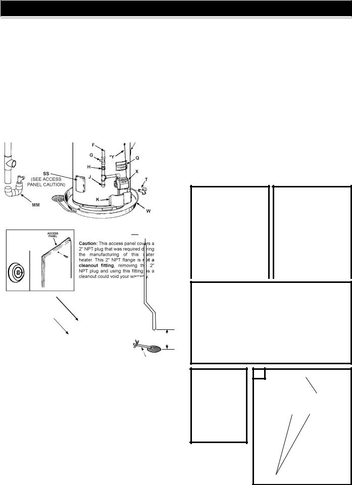
TYPICAL INSTALLATION
GET TO KNOW YOUR WATER HEATER - GAS MODELS
AVent Pipe
BAnode
CHot Water Outlet
D Outlet (120 VAC)
FGas Supply
GMain Manual Gas Shut Off Valve
HGround Joint Union J Dirt Leg
KOuter Door
LUnion
MInlet Water Shut Off Valve
NCold Water Inlet
OInlet Dip Tube
PTemperature & Pressure Relief Valve
SS
(SEE ACCESS PANEL CAUTION)
W
Q |
Rating Plate |
H H |
Bushing |
R |
Insulation |
II |
Nipple |
S |
Vent Terminal |
JJ |
Condensate Tee |
T |
Drain Valve |
KK |
Adapter |
U |
Igniter And Main Burner |
LL |
Plug |
W |
Drain Pan |
MM |
Vent Pipe Assembly #1 |
X |
Control |
NN |
Vent Pipe Assembly #2 |
Y |
Control Harness* |
OO |
Vent Pipe Assembly #3 |
AA |
Motor & Blower |
PP |
Side Recirculation Loop |
CC |
Condensate Fitting |
Inlet*** |
|
DD |
(4 Places Shown)** |
Side Recirculation Loop |
|
Plastic Top |
RR |
Outlet*** (not shown) |
|
EE |
On/Off Switch |
Vent Attenuation |
|
FF |
Exhaust Tee |
SS |
Assembly (VAA) (Optional) |
GG |
Elbow |
Access Door |
REPLACEMENT PARTS AND DELIMING PRODUCTS
Replacement parts and recommended delimer may be ordered through authorized servicers or distributors. When ordering parts, provide complete model and serial numbers (see rating plate), quantity and name of part desired. Standard hardware items may be purchased locally.
CONDENSATE ASSEMBLY
PP

(U)NATURAL GAS MAIN BURNER
WITH IGNITER ASSEMBLY SIDE VIEW
6 (15cm) MAXIMUM AIR GAP
TO A SUITABLE
DRAIN
(X) TEMPERATURE INDICATORS
TEMPERATURE ADJUSTMENT BUTTONS
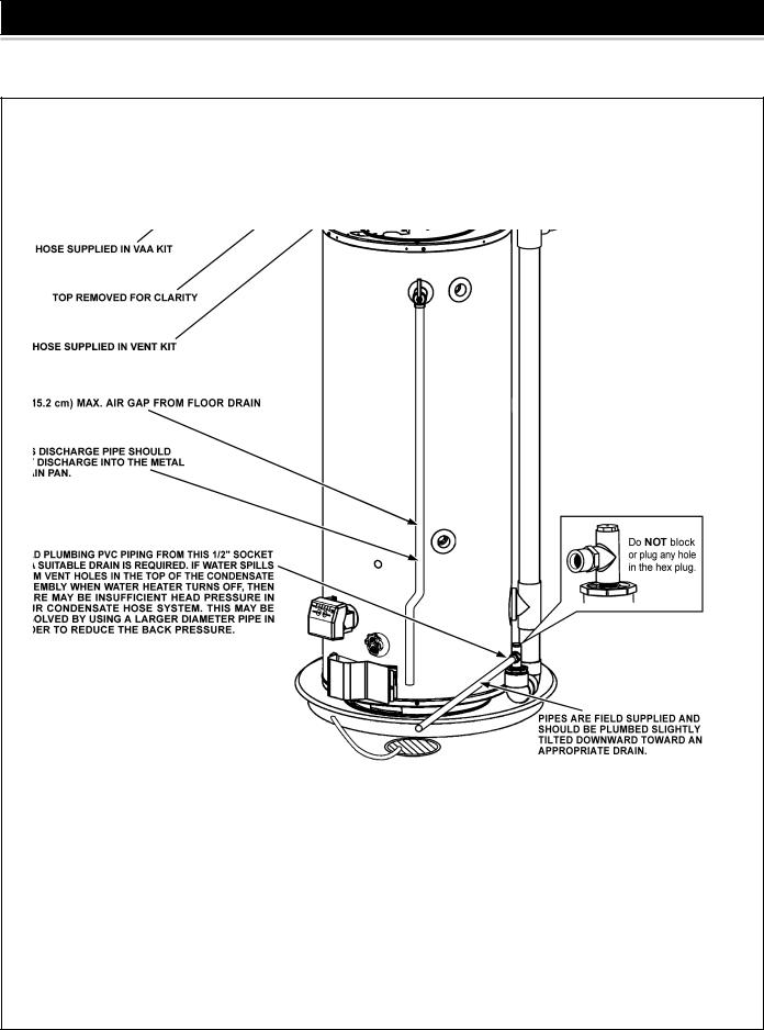
TYPICAL INSTALLATION
CONDENSATE HOSE AND DRAIN PAN
FIGURE 1 (continued).
8
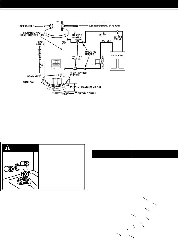
TYPICAL INSTALLATION
MIXING VALVE / THERMAL EXPANSION TANK USAGE AND SPACE HEATING
FIGURE 2.
Mixing Valves
DANGER |
can cause severe burns instantly |
|
Water temperature over 125°F (52°C) |
|
resulting in severe injury or death. |
|
Children, the elderly and the physically |
|
or mentally disabled are at highest risk |
|
for scald injury. |
|
Feel water before bathing or showering. |
|
Temperature limiting devices such as |
|
mixing valves must be installed when |
|
required by codes and to ensure safe |
|
temperatures at fixtures. |
Water heated to a temperature which will satisfy clothes washing, dish washing, and other sanitizing needs can scald and cause permanent injury upon contact. Short repeated heating cycles caused by small hot water uses can cause temperatures at the point of use to exceed the water heater’s temperature setting by up to 20°F (11°C).
Some people are more likely to be permanently injured by hot water than others. These include the elderly, children, the infirm and the physically/mentally disabled. Table 1 shows the approximate time- to-burn relationship for normal adult skin. If anyone using hot water provided by the water heater being installed fits into one of these groups or if there is a local code or state law requiring a certain water temperature at the point of use, then special precautions must be taken.
In addition to using lowest possible temperature setting that satisfies demand ofapplicationaMixingValveshouldbeinstalledatwaterheater(seeFigure 3) or at hot water taps to further reduce system water temperature.
Mixing valves are available at plumbing supply stores. Consult a
QualifiedInstallerorServiceAgency.Followmixingvalvemanufacturer’s instructions for installation of the valves.
|
|
TABLE 1. |
||||
Water Temperature |
|
|
Time to Produce 2nd & 3rd |
|||
|
Degree Burns on Adult Skin |
|||||
|
|
|
||||
180°F (82°C) |
|
|
Nearly instantaneous |
|||
|
|
|
|
|
|
|
170°F (77°C) |
|
|
Nearly instantaneous |
|||
160°F (71°C) |
|
|
About 1/2 second |
|||
150°F (66°C) |
|
|
About 1-1/2 seconds |
|||
140°F (60°C) |
|
|
Less than 5 seconds |
|||
130°F (54°C) |
|
|
About 30 seconds |
|||
120°F (49°C) |
|
|
More than 5 minutes |
|||
|
|
|
|
|
|
|
|
|
HOT WATER |
||||
|
|
|
OUTLET |
|||
|
|
|
|
|
||
|
|
|
|
|
|
|
|
|
|
|
12” TO 15” |
||
TEMPERED WATER |
(30-38 cm) |
|
||||
|
|
|
||||
|
OUTLET |
|
|
|
||
COLD |
|
|
|
CHECK |
||
WATER |
|
|
|
VALVE |
||
INLET |
|
|
|
MIXING |
||
|
|
|
CHECK |
|||
|
|
|
VALVE |
|||
|
|
|
VALVE |
|||
|
|
|
|
|
|
|
 TO TANK
INLET
FIGURE 3.
9
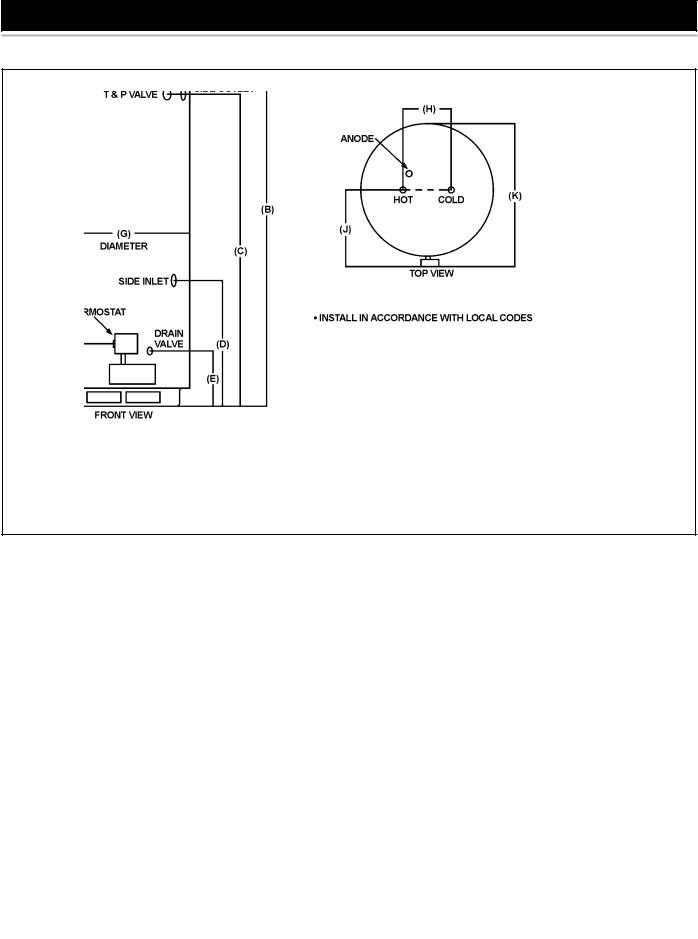
ROUGH-IN-DIMENSIONS
Rough-In-Dimensions
Top/Side Inlet and Outlet: 3/4” NPT
Gas Inlet: 1/2” NPT
Capacity and Gas and Electrical Characteristics
All models - Maximum Supply Pressure: 14 inches W.C. (3.48kPa) Minimum Supply Pressure Natural Gas: 5.0 inches W.C. (1.24kPa)
Minimum Pressure must be maintained under both load and no load (static and dynamic) conditions.
Recovery Capacities - U.S. Gallons/Hr. and Liters/Hr. at Temperature Rise Indicated
Recovery capacity based on 90% thermal efficiency.
10
LOCATING THE NEW WATER HEATER
Facts to Consider About the Location
Carefully choose an indoor location for the new water heater, because the placement is a very important consideration for the safety of the occupants in the building and for the most economical use of the appliance. This water heater is not for use in manufactured
(mobile) homes or outdoor installation.
Whether replacing an old water heater or putting the water heater in a new location, the following critical points must be observed:
1.Select a location indoors as close as practical to the vent terminal or location to which the water heater vent piping is going to be connected, and as centralized with the water piping system as possible.
2.Selected location must provide adequate clearances for servicing and proper operation of the water heater.
Installation of the water heater must be accomplished in such a manner that if the tank or any connections should leak, the flow will not cause damage to the structure. For this reason, it is not advisable to install the water heater in an attic or upper floor. When such locations cannot be avoided, a suitable drain pan should be installed under the water
heater. Drain pans are available at your local hardware store. Such a drain pan must have a clearance of at least 1.0” (2.5cm) greater than any point on the water heater’s outer jacket and must be piped to an adequate drain. The pan must not restrict combustion air flow. For example, if a circular pan is used, it must be a minimum of 27” (69cm) in diameter. See Figure 1.
Water heater life depends upon water quality, water pressure and the environment in which the water heater is installed. Water heaters are sometimes installed in locations where leakage may result in property damage, even with the use of a drain pan piped to a drain. However, unanticipated damage can be reduced or prevented by a leak detector or water shut-off device used in conjunction with a piped drain pan. These devices are available from some plumbing supply wholesalers and retailers, and detect and react to leakage in various ways:
•Sensors mounted in the drain pan that trigger an alarm or turn off the incoming water to the water heater when leakage is detected.
•Sensors mounted in the drain pan that turn off the water supply to the entire building when water is detected in the drain pan.
•Water supply shut-off devices that activate based on the water pressure differential between the cold water and hot water pipes connected to the water heater.
•Devices that will turn off the gas supply to a gas water heater while at the same time shutting off its water supply.
INSTALLATIONS IN AREAS WHERE FLAMMABLE LIQUIDS
(VAPORS) ARE LIKELY TO BE PRESENT OR STORED (GARAGES, STORAGE AND UTILITY AREAS, ETC.): Flammable liquids (such as gasoline, solvents, propane (LP or butane, etc.) and other substances (such as adhesives, etc.) emit flammable vapors which can be ignited by a gas water heater’s hot surface igniter or main burner. The resulting flashback and fire can cause death or serious burns to anyone in the area.
Also, the water heater must be located and/or protected so it is not subject to physical damage by a moving vehicle.
at least 18"(45.7cm) above the floor. This will reduce, but not eliminate, the risk
This water heater must not be installed directly on carpeting. Carpeting must be protected by metal or wood panel beneath the appliance extending beyond the full width and depth of the appliance
by at least 3” (7.6 cm) in any direction, or if the appliance is installed
11

in an alcove or closet, the entire floor must be covered by the panel. Failure to heed this warning may result in a fire hazard.
Minimum clearances between water heater and combustible construction are 0 inch at the sides and rear, 5.5” (14.0 cm) from the front and 12” (30.5 cm) from top. (Standard clearance.) If clearances stated on the heater differ from standard clearances, install water heater according to clearances stated on the heater.
Adequate clearance 24” (61.0 cm) for servicing this appliance should be considered before installation, such as changing the anodes, etc.
A minimum clearance of 5.5” (14.0 cm) must be allowed for access to replaceable parts such as thermostats, drain valve, relief valve and condensate drain.
When installing the heater, consideration must be given to proper location. Location selected should be as close to the wall as practicable and as centralized with the water piping system as possible.
FIGURE 4.
Agas water heater cannot operate properly without the correct amount of air for combustion. Do not install in a confined area such as a closet, unless you provide air as shown in the “Locating The New Water
Heater” section. Never obstruct the flow of ventilation air. If you have any doubts or questions at all, call your gas supplier. Failure to provide the proper amount of combustion air can result in a fire or explosion and cause death, serious bodily injury, or property damage.
FIGURE 5.
If this water heater will be used in beauty shops, barber shops, cleaning establishments, or self-service laundries with dry cleaning equipment, it is imperative that the water heater or water heaters be installed so that combustion and ventilation air be taken from outside these areas.
Propellants of aerosol sprays and volatile compounds, (cleaners, chlorine based chemicals, refrigerants, etc.) in addition to being highly flammable inmanycases,willalsoreacttoformcorrosive hydrochloric acid when exposed to the combustion products of the water heater. The results can be hazardous, and also cause product failure.
INSULATION BLANKETS
Insulation blankets are available to the general public for external use on gas water heaters but are not necessary with these products. The purpose of an insulation blanket is to reduce standby heat loss encountered with storage tank heaters. Your water heater meets or exceeds the Energy Policy Act standards with respect to insulation and standby loss requirements, making an insulation blanket unnecessary.
Should you choose to apply an insulation blanket to this heater, you should follow these instructions (For identification of components mentionedbelow,seeFigure1).Failuretofollowtheseinstructionscan restrict the air flow required for proper combustion, potentially resulting in fire, asphyxiation, serious personal injury or death.
•Do not apply insulation to the top of the water heater, as this will interfere with safe operation of the blower assembly.
•Do not cover the outer door, thermostat or temperature & pressure relief valve.
•Do not allow insulation to come within 2” (5.1 cm) of the floor to prevent blockage of combustion air flow to the burner.
•Do not cover the instruction manual. Keep it on the side of the water heater or nearby for future reference.
•Do obtain new warning and instruction labels from the manufacturer for placement on the blanket directly over the existing labels.
•Do inspect the insulation blanket frequently to make certain it does not sag, thereby obstructing combustion air flow.
Air REQUIREMENTs
For safe operation an adequate supply of fresh uncontaminated air for combustion and ventilation must be provided.
An insufficient supply of air can cause recirculation of combustion products resulting in contamination that may be hazardous to life.
12
 Loading...