


19" LCD Color Monitor |
AOC 917Sw |
Service
Service
Service
Horizontal Frequency
30-83 KHz
TABLE OF CONTENTS
Description |
Page |
Table Of Contents…………………………………………...1 |
|
Revision List…………………………………………………2 |
|
Important Safety Notice………………………….…………3 |
|
1. Monitor Specification..............................…………........4 |
|
2. LCD Monitor Description…………………………….......5 |
|
3. Operation Instruction…………………………...............6 |
|
3.1. General Instructions...........................…...................6 |
|
3.2. Control Buttons........................................................ |
6 |
3.3. OSD Menu….............................................................7 |
|
4. Input/Output Specification............………………..........9 |
|
4.1. Input Signal Connector............…………...................9 |
|
4.2. Power Supply Requirements.................................... |
9 |
4.3. Factory Preset Display Modes…….........................10 |
|
4.4. Panel Specification……………………………..…….10 |
|
5. Block Diagram…........................................................14 |
|
5.1. Software Flow Chart……………………………….....14 |
|
Description |
Page |
5.2.Electrical |
Block Diagram…...............................16 |
6.Schematic……………..........................................18 6.1.Main Board……….............................................18 6.2.Power Board...……...........................................23 6.3.Key Board...……................................................25 7.PCB Layout...…………........................................26 7.1.Main Board………...........................................26 7.2.Power Board….................................................28 7.4.Key Board…………..........................................30
8.Maintainability………............................................31 8.1.Equipments and Tools Requirement...............31 8.2.Trouble Shooting….………................................32
9.White-Balance, Luminance adjustment................38
10.Monitor Exploded View…...................................40 11.BOM List…………………………………...............41 12.Different Parts List……...………………...............54
SAFETY NOTICE
ANY PERSON ATTEMPTING TO SERVICE THIS CHASSIS MUST FAMILIARIZE HIMSELF WITH THE CHASSIS AND BE AWARE OF THE NECESSARY SAFETY PRECAUTIONS TO BE USED WHEN SERVICING ELECTRONIC EQUIPMENT CONTAINING HIGH VOLTAGES.
CAUTION: USE A SEPARATE ISOLATION TRANSFOMER FOR THIS UNIT WHEN SERVICING
1
19" LCD Color Monitor |
AOC 917Sw |
Revision List
Version |
Release Date |
Revision History |
TPV Model Name |
T98SM5NBUWA1NN
T9RSM5NLUWCKNZ
T9RSM5NPUWA5NN
T9RSM5NPUWA5NG
A00 |
Feb.-17-2008 |
Initial release |
T9RSM5NQUWA2NN
T9RSM5NQUWA3NN
T9RSM5NQUWA4NN
T9RSM5NKUWA2NN
2

19" LCD Color Monitor |
AOC 917Sw |
Important Safety Notice
Proper service and repair is important to the safe, reliable operation of all AOC Company Equipment. The service procedures recommended by AOC and described in this service manual are effective methods of performing service operations. Some of these service operations require the use of tools specially designed for the purpose. The special tools should be used when and as recommended.
It is important to note that this manual contains various CAUTIONS and NOTICES which should be carefully read in order to minimize the risk of personal injury to service personnel. The possibility exists that improper service methods may damage the equipment. It is also important to understand that these CAUTIONS and NOTICES ARE NOT EXHAUSTIVE. AOC could not possibly know, evaluate and advise the service trade of all conceivable ways in which service might be done or of the possible hazardous consequences of each way. Consequently, AOC has not undertaken any such broad evaluation. Accordingly, a servicer who uses a service procedure or tool which is not recommended by AOC must first satisfy himself thoroughly that neither his safety nor the safe operation of the equipment will be jeopardized by the service method selected.
Hereafter throughout this manual, AOC Company will be referred to as AOC.
WARNING
Use of substitute replacement parts, which do not have the same, specified safety characteristics may create shock, fire, or other hazards.
Under no circumstances should the original design be modified or altered without written permission from AOC. AOC assumes no liability, express or implied, arising out of any unauthorized modification of design.
Servicer assumes all liability.
FOR PRODUCTS CONTAINING LASER:
DANGER-Invisible laser radiation when open AVOID DIRECT EXPOSURE TO BEAM.
CAUTION-Use of controls or adjustments or performance of procedures other than those specified herein may result in hazardous radiation exposure.
CAUTION -The use of optical instruments with this product will increase eye hazard.
TO ENSURE THE CONTINUED RELIABILITY OF THIS PRODUCT, USE ONLY ORIGINAL MANUFACTURER'S REPLACEMENT PARTS, WHICH ARE LISTED WITH THEIR PART NUMBERS IN THE PARTS LIST SECTION OF THIS SERVICE MANUAL.
Take care during handling the LCD module with backlight unit
-Must mount the module using mounting holes arranged in four corners.
-Do not press on the panel, edge of the frame strongly or electric shock as this will result in damage to the screen. -Do not scratch or press on the panel with any sharp objects, such as pencil or pen as this may result in damage to the panel.
-Protect the module from the ESD as it may damage the electronic circuit (C-MOS). -Make certain that treatment person’s body is grounded through wristband.
-Do not leave the module in high temperature and in areas of high humidity for a long time. -Avoid contact with water as it may a short circuit within the module.
-If the surface of panel becomes dirty, please wipe it off with a soft material. (Cleaning with a dirty or rough cloth may damage the panel.)
3

19" LCD Color Monitor |
AOC 917Sw |
||||
1. Monitor Specifications |
|
|
|
||
|
|
Model number |
917Sw |
|
|
|
|
|
|
|
|
|
|
Driving system |
TFT Color LCD |
|
|
|
|
Viewable Image Size |
481mm diagoanl |
|
|
|
|
|
|
|
|
|
LCD Panel |
Pixel pitch |
0.2835mm(H) x 0.2835mm(V) |
|
|
|
|
|
|
|
|
|
Video |
R, G, B Analog lnterface |
|
||
|
|
|
|||
|
|
|
|
|
|
|
|
Separate Sync. |
H/V TTL |
|
|
|
|
|
|
|
|
|
|
Display Color |
16.7M Colors |
|
|
|
|
|
|
|
|
|
|
Dot Clock |
128 MHz |
|
|
|
|
|
|
|
|
|
|
Horizontal scan range |
30 kHz - 83 kHz |
|
|
|
|
|
|
|
|
|
|
Horizontal scan Size(Maximum) |
408.24mm |
|
|
|
|
|
|
|
|
|
|
Vertical scan range |
56 Hz - 75 Hz |
|
|
|
|
|
|
|
|
|
|
Vertical scan Size(Maximum) |
255.15mm |
|
|
|
|
Optimal preset resolution |
1440 x 900 (60 Hz) |
|
|
|
|
|
|
|
|
|
Resolution |
Highest preset resolution |
1440 x 900 (60 Hz) |
|
|
|
|
|
|
|
|
|
Plug & Play |
VESA DDC2B/CI |
|
||
|
|
|
|||
|
|
|
|
|
|
|
|
Input Connector |
D-Sub 15pin |
|
|
|
|
|
|
|
|
|
|
Input Video Signal |
Analog: 0.7Vp-p(standard), 75 OHM, Positive |
|
|
|
|
|
|
|
|
|
|
Power Source |
100~240VAC, 47~63Hz |
|
|
|
|
|
|
|
|
|
|
Power Consumption |
Active < 37W |
|
|
|
|
|
|
||
|
|
Standby < 1W |
|
||
|
|
|
|
|
|
|
|
|
|
|
|
|
|
Connector Type |
15-pin Mini D-Sub |
|
|
|
|
|
|
|
|
|
|
Signal Cable Type |
Detachable |
|
|
|
|
|
|
|
|
|
|
Dimensions & Weight: |
|
|
|
|
Physical |
|
|
|
|
|
Height (with base) |
439 mm |
|
||
|
Characteristics |
|
|
|
|
|
Width |
358 mm |
|
||
|
|
|
|
|
|
|
|
Depth |
204 mm |
|
|
|
|
|
|
|
|
|
|
Weight (monitor only) |
3.8 kg |
|
|
|
|
|
|
|
|
|
|
Weight (with packaging) |
4.7 kg |
|
|
|
|
|
|
|
|
|
|
Temperature: |
|
|
|
|
|
|
|
|
|
|
|
Operating |
0° to 50° |
|
|
|
|
|
|
|
|
|
|
Non-Operating |
-20°to 60° |
|
|
|
|
|
|
|
|
|
|
Humidity: |
|
|
|
|
Environmental |
|
|
|
|
|
Operating |
10% to 85% (non-condensing) |
|
||
|
|
|
|
|
|
|
|
Non-Operating |
5% to 80% (non-condensing) |
|
|
|
|
|
|
|
|
|
|
Altitude: |
|
|
|
|
|
|
|
|
|
|
|
Operating |
0~ 3000m (0~ 10000 ft ) |
|
|
|
|
|
|
|
|
|
|
Non-Operating |
0~ 5000m (0~ 15000 ft ) |
|
|
|
|
|
|
|
|
4
19" LCD Color Monitor |
AOC 917Sw |
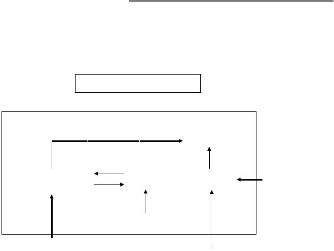
2. LCD Monitor Description
The LCD monitor will contain a main board, a power board and a key board which house the flat panel control logic, brightness control logic and DDC.
The power board will provide AC to DC Inverter voltage to drive the backlight of panel and the main board chips each voltage.
Monitor Block Diagram
CCFL Drive. |
Flat Panel and |
|
CCFL backlight |
||
|
||
|
|
|
|
|
|
|
|
|
|
RS232 Connector |
Power board |
|
|
Main Board |
|
|
|||
(Include: adapter, inverter) |
|
|
|
|
For white balance |
|||
|
|
|
|
|
|
|
||
|
|
|
|
|
|
|
|
adjustment in factory |
|
|
|
|
|
|
|||
|
|
|
|
|
|
|
|
mode |
|
|
|
Key Board |
|
|
|
|
|
|
|
|
|
|
Video signal, DDC |
|||
|
|
|
|
|
|
|
|
|
|
|
|
|
|
|
|
|
|
AC-IN |
|
|
|
|
|
|
|
|
|
|
|
|
HOST Computer |
|
|
|
|
100V-240V |
|
|
|
|
|
|
|
|
|
|
|
|
|
|
|
|
|
5
19" LCD Color Monitor |
AOC 917Sw |
3. Operating Instructions
3.1 General Instructions
Press the power button to turn the monitor on or off. The other control buttons are located at the front of the panel of the monitor.
By changing these settings, the picture can be adjusted to your personal preferences.
-The power cord should be connected.
-Connect the video cable from the monitor to the video card.
-Press the power button to turn on the monitor, the power indicator will light up.
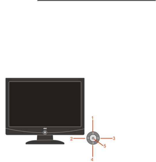
3.2Control Buttons
3.2.1 Key Control
1. Eco Mode / Up 2. Exit / - 3. Menu / + 4. Auto / Down 5. Power on/off
3.2.2 Key Function
1)Press the MENU-button ( ) to activate the OSD window.
2)Press or
or  to navigate through the functions. Once the desired function is highlighted, press the MENU-button to activate sub-menu . Once the desired function is highlighted, press MENU-button to activate it.
3)Press  or
or  to change the settings of the selected function. Press
  or
or  to select another function in sub-menu . Press AUTO(
 ) to exit . If you want to adjust any other function, repeat steps 2-3.
4)OSD Lock Function: To lock the OSD, press and hold the MENU button while the monitor is off and then press power button to turn the monitor on. To un-lock the OSD - press and hold the MENU button while the monitor is off and then press power button to turn the monitor on.
5)Eco Mode hot key ( ) : Press the Eco key continuously to select the Eco mode of brightness when there is no OSD ( Eco mode hot key may not be available in all models).
6)Volume adjustment hot key : When there is no OSD , press Volume ( ) to active volume adjustment bar, press
  or
or  to adjust volume ( Only for the models with speakers).
6
19" LCD Color Monitor |
AOC 917Sw |
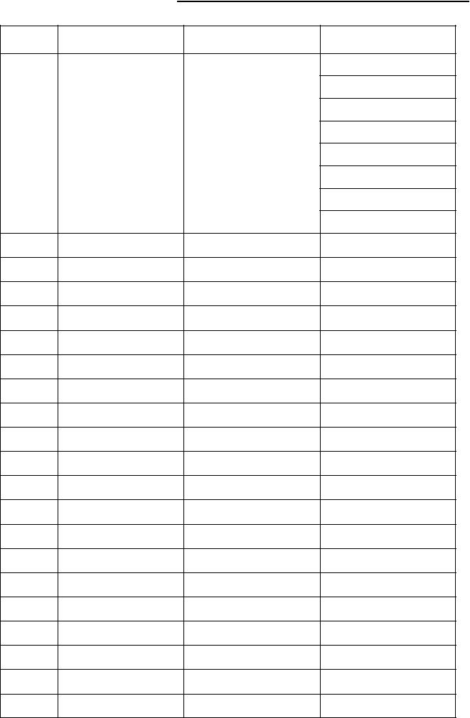
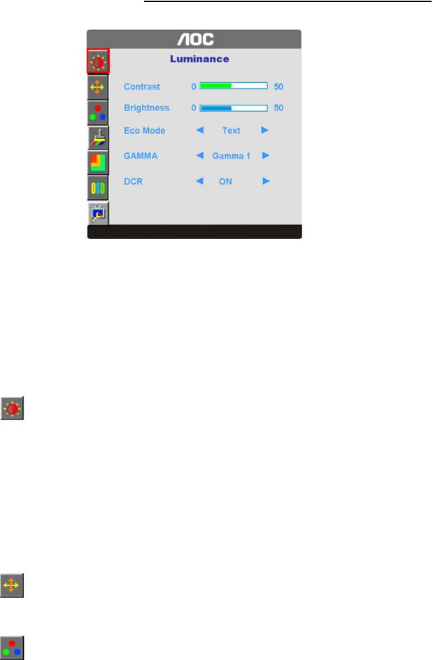
3.3 OSD Menu |
|
OSD Function Introduction |
|
|
|
Luminance |
Adjust Range |
Description |
|
Brightness |
0-100 |
Backlight Adjustment |
|
Contrast |
0-100 |
Contrast from Digital-register |
|
|
Standard |
Standard Mode |
|
|
Text |
Text Mode |
|
Eco mode |
Internet |
Internet Mode |
|
Game |
Game Mode |
||
|
|||
|
Movie |
Movie Mode |
|
|
Sports |
Sports Mode |
|
|
Gamma1 |
Adjust to Gamma 1 |
|
Gamma |
Gamma2 |
Adjust to Gamma 2 |
|
|
Gamma3 |
Adjust to Gamma 3 |
|
DCR |
Off |
Disable dynamic contrast ratio |
|
On |
Enable dynamic contrast ratio |
||
|
|||
Image Setup |
|
|
|
Clock |
0-100 |
Adjust picture Clock to reduce Vertical-Line noise. |
|
Focus |
0-100 |
Adjust Picture Phase to reduce Horizontal-Line noise |
|
H.Position |
0-100 |
Adjust the horizonal position of the picture. |
|
V.Position |
0-100 |
Adjust the vertical position of the picture |
|
Color Temp. |
|
|
|
Warm |
|
Recall Warm Color Temperature from EEPROM. |
|
Normal |
|
Recall Normal Color Temperature from EEPROM. |
|
Cool |
|
Recall Cool Color Temperature from EEPROM. |
7
19" LCD Color Monitor |
AOC 917Sw |
sRGB |
|
Recall SRGB Color Temperature from EEPROM. |
|
|
User-B |
Blue Gain from Digital-register |
|
|
User-G |
Green Gain Digital-register. |
|
User |
User-R |
Red Gain from Digital-register |
|
|
User-Y |
Yellow Gain from Digital-register |
|
|
User-C |
Cyan Gain from Digital-register |
|
Color Boost |
|
|
|
Full |
on or off |
Disable or Enable Full Enhance Mode |
|
Enhance |
|||
|
|
||
Nature Skin |
on or off |
Disable or Enable Nature Skin Mode |
|
Green Field |
on or off |
Disable or Enable Green Field Mode |
|
Sky-blue |
on or off |
Disable or Enable Sky-blue Mode |
|
AutoDetect |
on or off |
Disable or Enable AutoDetect Mode |
|
Demo |
on or off |
Disable or Enable Demo |
|
Picture |
|
|
|
Boost |
|
|
|
Frame Size |
0-100 |
Adjust Frame Size |
|
Brightness |
0-100 |
Adjust Frame Brightness |
|
Contrast |
0-100 |
Adjust Frame Contrast |
|
Hue |
0-100 |
Adjust Frame Hue |
|
Saturation |
0-100 |
Adjust Frame Saturation |
|
Position |
H. position |
Adjust Frame horizontal Position |
|
V.position |
Adjust Frame vertical Position |
||
|
|||
OSD Setup |
|
|
|
H.Position |
0-100 |
Adjust the horizontalposition of OSD |
|
V.Position |
0-100 |
Adjust the vertical position of OSD |
|
Timeout |
0-100 |
Adjust the OSD Timeout |
|
Language |
|
Select the OSD language |
|
Extra |
|
|
|
Auto Config |
yes or no |
Auto adjust the picture to default |
|
Reset |
yes or no |
Reset the menu to default |
|
DDC-CI |
|
Turn ON/OFF DDC-CI Support |
|
Information |
|
Show the information of the main image and |
|
|
sub-image source |
||
|
|
8
19" LCD Color Monitor |
AOC 917Sw |
4. Input/Output Specification
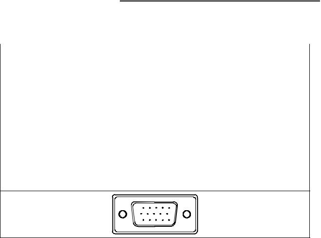
4.1 Input Signal Connector
Analog connectors
Pin No. |
Description |
Pin No. |
Description |
|
|
|
|
1. |
Red Video |
9. |
+5V |
|
|
|
|
2. |
Green Video |
10. |
Ground |
|
|
|
|
3. |
Blue Video |
11. |
N.C. |
|
|
|
|
4. |
N.C. |
12. |
DDC-Serial Data |
|
|
|
|
5. |
Detect Cable |
13. |
H-Sync |
|
|
|
|
6. |
Red Ground |
14. |
V-Sync |
|
|
|
|
7. |
Green Ground |
15. |
DDC-Serial Clock |
|
|
|
|
8. |
Blue Ground |
|
|
|
|
|
|
VGA connector layout
1 |
5 |
6 |
10 |
11 |
15 |
4.2 Power Supply Requirements
A/C Line voltage range |
100 V ~ 240 V |
|
|
|
|
A/C Line frequency range |
50 ± 3Hz, 60 ± 3Hz |
|
|
|
|
Current |
1.5A max at 100V; 0.8A max at 240 V |
|
|
|
|
Peak surge current |
< 55A peak at 240 VAC and cold starting |
|
|
|
|
Leakage current |
< 3.5mA |
|
|
|
|
Power line surge |
No advance effects (no loss of information or defect) |
|
with a maximum of 1 half-wave missing per second |
||
|
||
|
|
|
DC output Voltage |
: 5VDC ± 5 ; 12VDC± 5 |
|
|
|
|
CURRENT |
1.5Amp (5V) 2 Amp (12V) |
|
|
|
\
9
19" LCD Color Monitor |
|
|
|
|
AOC 917Sw |
|||
4.3 Factory Preset Display Modes |
|
|
|
|||||
|
|
|
|
|
|
|
|
|
|
Stand |
|
Resolution |
Horizontal |
Vertical |
|
||
|
|
Frequency(Khz) |
Frequency(Hz) |
|
||||
|
|
|
|
|
|
|
||
|
|
|
|
|
|
|
||
|
Dos-mode |
|
720 × 400 |
31.47kHz |
70.0Hz |
|
||
|
|
|
|
|
|
|
|
|
|
VGA |
|
640 |
× 480 |
31.47kHz |
60.0Hz |
|
|
|
|
|
|
|
|
|
|
|
|
|
640 |
× 480 |
37.50kHz |
75.0Hz |
|
||
|
|
|
|
|||||
|
|
|
|
|
|
|
|
|
|
SVGA |
|
800 |
× 600 |
37.879kHz |
60.0Hz |
|
|
|
|
|
|
|
|
|
|
|
|
|
800 |
× 600 |
46.875kHz |
75.0Hz |
|
||
|
|
|
|
|||||
|
|
|
|
|
|
|
||
|
|
|
1024 × 768 |
48.363kHz |
60.0Hz |
|
||
|
XGA |
|
|
|
|
|
||
|
|
1024 × 768 |
56.476kHz |
70.0Hz |
|
|||
|
|
|
|
|
|
|
||
|
|
|
1024 × 768 |
60.021kHz |
75.0Hz |
|
||
|
|
|
|
|
|
|
|
|
|
SXGA |
|
1280 |
× 1024 |
64.000kHz |
60.0Hz |
|
|
|
|
|
|
|
|
|
|
|
|
|
1280 |
× 1024 |
80.000kHz |
75.0Hz |
|
||
|
|
|
|
|||||
|
|
|
|
|
|
|
||
|
WXGA |
|
1440 × 900 |
55.935kHz |
59.8Hz |
|
||
|
|
|
|
|
|
|
|
|
4.4 Panel Specification
4.4.1 General Features
10
19" LCD Color Monitor |
AOC 917Sw |
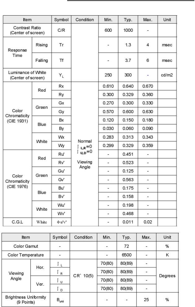
4.4.2 Display Characteristics
11
19" LCD Color Monitor |
AOC 917Sw |
4.4.3 Optical Characteristics
12

19" LCD Color Monitor |
AOC 917Sw |
4.4.4Electrical Characteristics
(1)TFT-LCD
(2) Backlight
13
19" LCD Color Monitor
5. Block Diagram
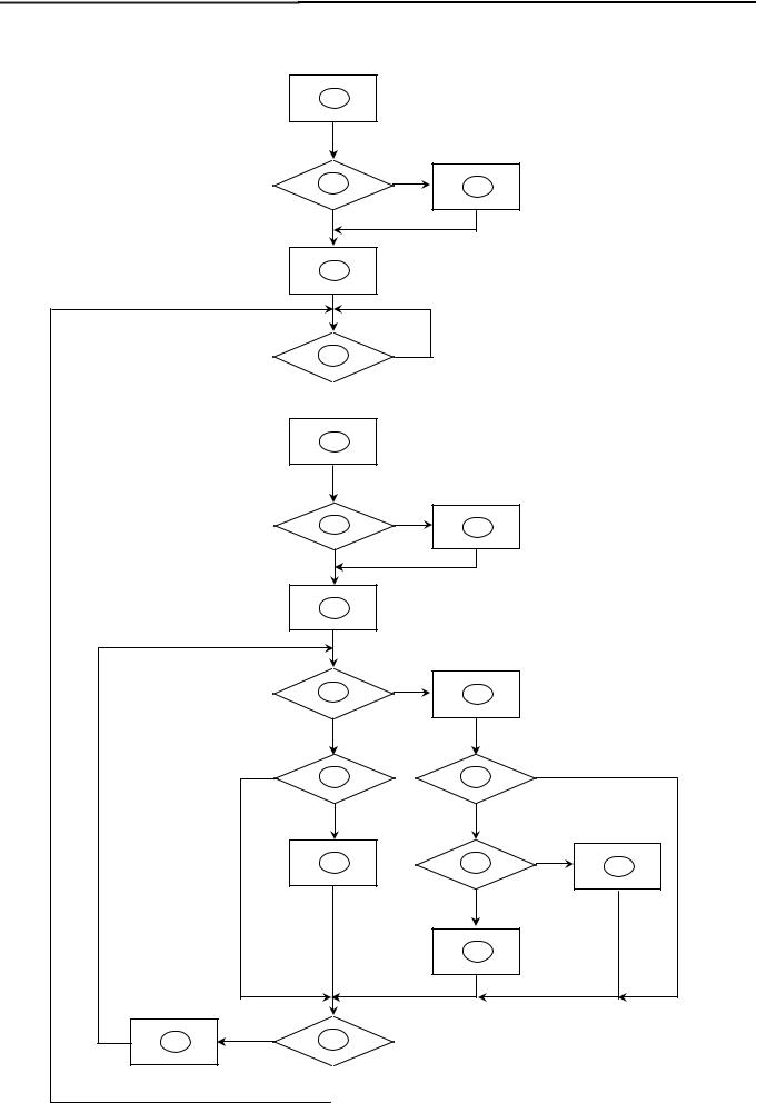
5.1 Software Flow Chat
1
2
N
4
5
 Y
Y
6
7
Y
9
AOC 917Sw
Y
3
N
N
8
|
10 |
N |
|
|
11 |
|
|
|
Y |
|
|
N |
12 |
13 |
N |
|
|
||
|
Y |
Y |
|
|
14 |
15 |
N |
|
16 |
||
|
|
Y |
|
|
|
17 |
|
N
18 19
 Y
Y
14
19" LCD Color Monitor |
AOC 917Sw |
1)MCU initialize.
2)Is the EPROM blank?
3)Program the EPROM by default values.
4)Get the PWM value of brightness from EPROM.
5)Is the power key pressed?
6)Clear all global flags.
7)Are the AUTO and SELECT keys pressed?
8)Enter factory mode.
9)Save the power key status into EPROM. Turn on the LED and set it to green color. Scalar initializes.
10)In standby mode?
11)Update the lifetime of back light.
12)Check the analog port, are there any signals coming?
13)Does the scalar send out an interrupt request?
14)Wake up the scalar.
15)Are there any signals coming from analog port?
16)Display "No connection Check Signal Cable" message. And go into standby mode after the message disappear.
17)Program the scalar to be able to show the coming mode.
18)Process the OSD display.
19)Read the keyboard. Is the power key pressed?
15
19" LCD Color Monitor |
AOC 917Sw |
5.2 Electrical Block Diagram |
|
5.2.1 Main Board |
|
Crystal 14.318MHZ |
|
Panel Interface |
(X401) |
|
(CN403) |
|
|
|
|
|
Scalar TSUM1PFR |
|
|
FLASH ROM |
|
|
|
|
|
(Include ADC, OSD, MCU) |
|
Key Control Interface |
|
SST25LF020A |
|
|
||
|
|
(CN402) |
||
(U402) |
|
|
|
|
|
(U401) |
|
|
|
|
|
|
||
|
|
|
|
|
|
|
|
||
|
|
|
|
|
D-Sub Connector
(CN101)
16
19" LCD Color Monitor |
AOC 917Sw |
5.2.2 Inverter/Power Board
AC input |
|
|
|
|
|
Bridge |
|
|
|
|
|
Rectifier |
|
|
|
|
|
|
|
|
|
|
Transformer |
|
|
|
|
||||||||
|
EMI filter |
|
|
|
Rectifier |
|
|
|
diodes |
|
|
|
|
||||
|
|
|
|
and Filter |
|
|
|
|
|
|
|
|
|
|
|||
|
|
|
|
|
|
|
|
|
|
|
|
|
|
|
|
||
|
|
|
|
|
|
|
|
|
|
|
|
|
|
|
|
|
|
|
|
|
|
|
|
|
|
|
|
|
|
|
|
|
|
|
|
|
|
|
|
|
|
|
|
|
|
|
|
|
|
|
|
|
|
|
|
|
Start Circuit: R932, R933 |
|
|
|
|
|
CN902 |
||||||||
|
|
|
|
|
|
|
|
|
|
|
|
|
|
|
|||
|
|
|
|
|
|
|
|
|
|
|
|
|
|
|
|
|
|
|
|
|
|
|
|
|
|
|
|
|
|
|
|
|
5V |
||
|
|
|
|
|
|
|
|
|
|
|
|
|
Feedback |
|
|||
|
|
|
|
|
PWM |
|
|
|
|
|
|
|
|
|
|
||
|
|
|
|
|
|
|
|
|
|
|
|
|
|
||||
|
|
|
|
|
|
|
|
|
|
|
Circuit |
|
|
|
|
||
|
|
|
|
|
Control IC |
|
|
|
|
|
|
12V |
|||||
|
|
|
|
|
|
|
|
|
|
|
|
|
|
||||
|
|
|
|
|
|
|
|
|
|
|
|
|
|
|
|
|
|
ON/OFF
|
|
|
Output |
|
|
|
|
|
|
|
|
|
|
|
|
|
|
Transformer |
|
MOSFET |
|
|
|||
|
|
|
Circuit |
|
|
|
|
|
||||
|
|
|
|
|
|
|
|
|
|
|
|
|
|
|
|
|
|
|
|
|
|
|
|
||
|
|
|
|
|
|
|
|
|
|
|
|
|
|
|
|
|
|
|
|
|
|
|
|
|
|
Lamp |
|
|
|
|
|
|
|
|
|
|
|
ON/OFF |
|
|
|
|
|
|
|
|
|
|
|
||
|
|
|
|
|
|
|
|
|
|
|
||
|
|
Feedback |
|
|
|
|
|
PWM |
|
|
Control |
|
|
|
|
|
|
|
|
|
|
||||
|
|
|
Circuit |
|
|
|
|
|
Control IC |
|
|
|
|
|
|
|
|
|
|
|
|
DIM |
|||
|
|
|
|
|
|
|
|
|
|
|||
|
|
|
|
|
Over Voltage |
|
|
IC801 |
|
|
||
|
|
|
|
|
|
|
|
|
||||
|
|
|
|
|
|
|
|
|
|
|
|
|
|
|
|
|
|
|
|
|
|
|
|
|
|
|
|
|
|
|
|
|
|
|
|
|
|
|
17
19" LCD Color Monitor |
AOC 917Sw |
6. Schematic
6.1Main Board
715G2904 1
|
|
|
|
|
|
|
|
|
|
|
|
|
|
|
|
|
TSUM1PFR |
|
SCHEMATIC |
|
|||||||||||||||||||||||||||||||||||||
|
|
|
|
|
|
|
|
|
|
|
|
|
|
|
|
|
|
|
|
|
|
XGA/SXGA |
|
|
|
|
|
LVDS OUTPUT |
|
||||||||||||||||||||||||||||
|
|
|
|
|
|
|
|
|
|
|
|
|
|
|
|
|
|
|
|
|
|
|
|
|
|
|
DSUB_R+ |
|
|
|
DSUB_R+ |
|
|
|
|
VCC1.8 |
|
|
|
|
|
|
|
|
|
|
|
|
|
|
|
||||||
|
|
|
|
|
|
|
|
|
|
|
|
|
|
|
|
|
|
|
|
|
|
|
|
|
|
|
|
|
|
|
|
|
|
|
|
|
|
|
|
|
|
|
|
|
|
|
|||||||||||
|
|
|
|
|
|
|
|
|
|
|
|
|
|
|
|
|
|
|
|
|
|
|
|
|
|
|
DSUB_R- |
|
|
|
DSUB_R- |
|
|
|
|
|
|
|
|
|
|
|
|
|
|
|
|
|
|
|
|
|
|
|
|
|
|
|
|
|
|
|
|
|
|
|
|
|
|
|
|
|
|
|
|
|
|
|
|
|
|
|
|
|
DSUB_G+ |
|
|
|
DSUB_G+ |
|
|
|
|
|
|
|
VCC3.3 |
|
|
|
|
|
|
|
|
|
|
|
|
|
|
|
|||
|
|
|
|
|
|
|
|
|
|
|
|
|
|
|
|
|
|
|
|
|
|
|
|
|
|
|
|
|
|
|
|
|
|
|
|
|
|
|
|
|
|
|
|
|
|
|
|
|
|
|
|||||||
|
|
|
|
|
|
|
|
|
|
|
|
|
|
|
|
|
|
|
|
|
|
|
|
|
|
|
DSUB_G- |
|
|
|
DSUB_G- |
|
VCC1.8 |
|
|
|
|
|
|
|
|
|
|
|
|
|
|
|
|
|
|
|
|
|
|
|
|
|
|
|
|
|
|
|
|
|
|
|
|
|
|
|
|
|
|
|
|
|
|
|
|
|
|
|
DSUB_SOG |
|
|
|
DSUB_SOG |
|
|
|
|
|
|
|
|
|
|
|
CMVCC |
|
|||||||||||||
|
|
|
|
|
|
|
|
|
|
|
|
|
|
|
|
DSUB_5V |
|
|
DSUB_B+ |
|
|
|
DSUB_B+ |
|
|
|
|
|
|
|
|
|
|
|
|
|
|
|
|
|
|
|
|
|
|
|
|
|
|
||||||||
|
|
|
|
|
|
|
|
|
|
|
|
|
|
|
|
|
|
|
|
|
|
|
|
|
|
|
DSUB_B- |
|
|
|
DSUB_B- |
|
VCC3.3 |
|
|
|
|
|
|
|
|
|
|
|
|
CMVCC1 |
|
||||||||||
|
|
|
|
|
|
|
|
|
|
|
|
|
|
|
|
|
|
|
|
|
|
|
|
|
|
|
|
|
|
|
|
|
|
|
|
|
|
|
|
|
|
|
|
||||||||||||||
|
|
|
|
|
|
|
|
|
|
|
|
|
ESD_VCC |
|
|
|
|
|
|
|
|
DSUB_H |
|
|
|
DSUB_H |
|
|
|
|
|
|
|
|
|
|
|
|
|
|
|
|
|
|
|
|
|
|
|
|
|
|
|||||
|
|
|
|
|
|
|
|
|
|
|
|
|
|
|
|
|
|
|
|
|
|
|
|
|
|
|
|
|
|
|
|
|
|
|
|
|
|
|
|
|
|
|
|||||||||||||||
|
|
|
|
|
|
|
|
|
|
|
|
|
|
|
|
|
|
|
|
|
|
|
|
|
|
|
DSUB_V |
|
|
|
DSUB_V |
|
|
|
|
|
|
|
|
|
|
|
|
|
|
|
|
|
|
|
|
|
|
|
|
|
|
|
|
|
|
|
|
|
|
VCC3.3 |
|
|
|
|
|
|
|
|
|
DSUB_5V DDC1_SDA |
|
|
|
DDC1_SDA |
|
CMVCC |
|
|
|
|
|
|
|
|
|
|
|
|
|
|
|
|
|
|
|
|
|
|
|
|
|||||||||
|
|
|
|
|
|
|
|
|
|
|
|
|
|
|
|
|
|
|
|
|
|
|
|
|
|
|
DDC1_SCL |
|
|
|
DDC1_SCL |
|
|
|
|
|
|
|
|
|
|
|
|
|
|
|
|
|
|
|
|
|
|
|
|
|
|
|
|
|
|
|
|
|
|
|
|
|
|
|
|
|
|
|
|
|
|
|
|
|
|
|
|
ESD_VCC DET_CABLE |
|
|
|
DET_CABLE |
|
CMVCC1 |
|
|
|
|
|
|
|
|
|
|
|
|
|
|
|
|
|
|
|
|
|
|
|
|
|
|
|
|
|
|
|
|
|
|
|
|
|
|
|
|
|
|
|
|
|
|
|
|
|
|
|
|
|
|
|
|
|
|
|
|
|
|
|
|
|
|
|
|
|
|
|
|
|
|
|
|
|
|
|||||
|
|
|
|
|
|
|
|
|
|
|
|
|
|
|
|
|
|
|
|
|
|
|
|
|
|
VCC3.3 |
|
|
|
|
|
|
|
|
|
|
|
|
|
|
|
|
|
|
|
|
|
|
|
|
|
|
|
|
|
||
|
|
|
|
|
|
|
|
|
|
|
|
|
|
|
|
|
|
|
|
|
|
|
|
|
|
|
|
|
|
|
|
|
|
|
|
|
|
|
|
|
|
|
|
|
|
|
|
|
|
|
|
|
|||||
|
|
|
|
|
|
|
|
|
|
|
|
|
|
|
|
|
|
|
|
|
|
|
|
|
|
|
|
|
|
|
|
|
|
|
|
|
|
|
|
|
|
|
|
|
|
|
|
|
|
|
|
|
|
|
|
||
|
|
|
|
|
|
|
|
|
|
|
|
|
|
|
|
|
|
|
|
|
|
|
|
|
|
|
|
|
|
|
|
|
|
|
|
|
|
|
|
|
|
|
|
|
|
|
|
|
|
|
|
|
|
|
|||
|
|
|
|
|
|
|
|
|
|
|
|
|
|
|
|
|
|
|
|
|
|
|
|
|
|
|
|
|
|
|
|
|
|
|
|
|
|
|
|
|
|
|
|
|
|
|
|
|
|
|
|
|
|
|
|
||
|
|
|
|
|
|
|
|
|
|
|
|
|
|
|
|
|
|
|
|
|
|
|
|
|
02.Input |
|
|
|
|
|
|
|
|
|
|
|
|
|
|
|
|
|
|
|
|
|
|
|
|
|
|
|
|
|
|
||
|
|
|
|
|
|
|
|
|
|
|
|
|
|
|
|
|
VCC1.8 |
|
|
|
|
|
|
|
|
|
|
|
|
|
|
|
|
|
|
|
|
|
|
|
|
|
|
|
CMVCC |
|
|||||||||||
|
|
|
|
|
|
|
|
|
|
|
|
|
|
|
|
|
|
|
|
|
|
|
|
|
|
|
|
|
|
|
|
|
|
|
|
|
|
|
|
|
|
|
|
||||||||||||||
|
|
|
|
|
|
|
|
|
|
|
|
|
|
VCC3.3 |
|
|
|
|
|
|
|
|
|
|
|
|
PA[0..1] |
|
|
|
|
PA[0..1] |
|
|
|
PA[0..1] |
|
|
|
|
|
|
|
||||||||||||||
|
|
|
|
|
|
|
|
|
|
|
|
|
|
|
|
|
|
|
|
|
|
|
|
|
|
|
|
|
|
|
|
|
|
||||||||||||||||||||||||
|
|
|
|
|
|
|
|
|
|
|
|
|
|
|
|
|
|
|
|
|
|
|
|
|
|
|
|
|
|
|
|
|
|
|
|
|
|
|
|
|
|
|
|
|
|
|
|
|
|
||||||||
|
|
|
|
|
|
|
|
|
DSUB_5V |
|
|
|
|
|
|
VCC1.8 |
|
|
|
|
|
|
|
|
|
|
|
PA[4..9] |
|
|
|
|
|
|
CMVCC |
|
|
|
|
|
|
|
|
||||||||||||||
|
|
|
|
|
|
|
|
|
|
|
|
|
|
|
|
|
|
|
|
|
|
|
|
|
|
|
|
|
|
|
|
|
|
|
|
|
|
|
|
||||||||||||||||||
|
|
|
|
|
|
|
|
|
|
|
|
|
|
|
|
|
|
|
|
|
|
|
|
|
|
on_BACKLIGHT |
|
|
|
on_BACKLIGHT |
|
PA[4..9] |
|
|
|
|
|
|
|
|
|
|
|
PA[4..9] |
|
|
|
|
|||||||||
|
|
|
|
|
|
|
|
|
|
|
|
|
|
|
|
|
|
|
|
|
|
|
|
|
|
|
|
|
|
|
|
|
|
PB[0..9] |
|
|
|
|
|
|
|
|
|
|
|||||||||||||
|
|
|
|
|
|
CMVCC |
|
|
|
|
|
|
|
|
|
|
|
|
|
VCC3.3 |
|
|
|
|
|
PB[0..9] |
|
|
|
|
|
|
|
PB[0..9] |
|
|
|
|
|
|
|
||||||||||||||||
|
|
|
|
|
|
|
|
|
|
|
|
|
|
|
|
|
|
|
|
|
|
|
|
|
|
|
|
|
|
|
|
|
|
|
|||||||||||||||||||||||
|
|
|
|
|
|
|
|
|
|
|
|
|
|
|
|
|
|
|
|
|
|
|
|
|
|
|
|
|
|
|
|
|
|
|
|
|
|
|
|
|
|
||||||||||||||||
|
|
|
|
|
|
|
|
|
|
|
|
|
|
|
|
|
|
|
|
|
|
|
|
|
|
|
Mute |
|
|
|
Mute |
|
|
|
|
|
|
|
|
|
|
|
|
|
|
|
|
|
|
|
|
|
|
|
|
|
|
|
|
|
|
|
|
|
|
|
|
|
|
|
|
|
|
|
|
|
|
|
|
|
|
|
|
|
Volume# |
|
|
|
Volume# |
PPWR_ON# |
|
|
|
|
|
|
|
|
|
|
|
PPWR_ON# |
|
|
|
|
|
|
|
||||||
|
|
|
CMVCC1 |
|
|
|
|
|
|
|
|
|
|
|
|
|
|
|
|
|
DSUB_5V PANEL_ID# |
|
|
|
PANEL_ID# |
|
|
|
|
|
|
|
|
|
|
|
|
|
|
|
|
|
|
|
|
|
|
|
|
|
|
||||||
|
|
|
|
|
|
|
|
|
|
|
|
|
|
|
|
|
|
|
|
|
|
|
|
|
|
|
|
|
|
|
|
|
|
|
|
|
|
|
|
||||||||||||||||||
|
|
|
|
|
|
|
|
|
|
|
|
|
|
|
|
|
|
|
|
|
|
|
|
|
|
|
|
|
|
|
|
|
|
|
|
|
|
|
|
|
|
|
|
|
|
|
|
|
|
||||||||
|
|
|
|
|
|
|
|
|
|
|
|
|
|
|
|
|
|
|
|
|
|
|
|
|
|
Adj_BACKLIGHT |
|
|
|
Adj_BACKLIGHT |
|
|
|
|
|
|
|
|
|
|
|
|
|
|
|
|
|
|
|
|
|
|
|
|
|
|
|
|
|
|
|
|
|
|
|
|
|
|
|
|
|
|
|
|
|
|
|
|
|
|
|
|
|
CMVCC |
|
|
|
|
|
|
|
|
|
|
|
|
|
|
|
|
|
|
|
|
|
|
|
|
|
|
|
|
|
|
|
ESD_VCC |
|
|
|
|
|
|
|
|
|
|
|
|
|
|
|
|
|
|
|
|
|
|
VCTRL |
|
|
|
VCTRL |
|
|
|
|
|
|
|
|
|
|
|
|
|
|
|
|
|
|
|
|
|
|
|
|
|
|
||||
|
|
|
|
|
|
|
|
|
|
|
|
|
|
|
|
|
|
|
|
|
|
|
|
|
|
|
|
|
|
|
|
|
|
|
|
|
|
|
|
|
|
|
|
|
|
|
|
|
|||||||||
|
|
|
|
|
|
|
|
|
|
CMVCC1 |
|
|
|
|
|
|
|
|
|
|
|
|
|
|
|
|
|
|
|
|
|
|
|
|
|
|
|
|
|
|
|||||||||||||||||
|
|
|
|
|
|
|
|
|
|
|
|
|
|
|
|
|
|
|
|
|
|
|
|
|
|
|
|
|
|
|
|
|
|
|
|
|
|
|
|
|
|
|
|
|
|
|
|
|
|
|
|
|
|
|
|
||
|
|
|
|
|
|
|
|
|
|
|
|
|
|
|
|
|
|
|
|
|
|
|
|
|
|
ESD_VCC |
|
|
|
|
|
|
|
|
|
|
|
|
|
|
|
|
|
|
|
|
|
|
|
|
|
|
|
|
|
|
|
|
|
|
|
|
|
|
|
|
|
|
|
|
|
|
|
|
|
|
|
|
|
|
|
|
|
|
|
|
|
|
|
|
|
|
|
|
|
|
|
|
|
|
|
|
|
|
|
|
|
|
|
|
|
|
|
||
|
|
|
|
|
|
|
|
|
|
|
|
|
|
|
|
|
|
|
|
|
|
|
|
|
|
|
|
|
|
|
|
|
|
|
|
|
|
|
|
|
|
|
|
|
|
|
|
|
|
|
|
|
|
|
|||
|
|
|
|
|
|
|
|
|
|
|
|
|
|
|
|
|
|
|
|
|
|
|
|
|
|
|
|
|
|
|
|
|
|
|
|
|
|
|
|
|
|
|
|
|
|
|
|
|
|
|
|
|
|
|
|
||
|
|
|
|
|
|
|
|
|
|
|
|
|
|
|
|
|
|
|
|
|
|
|
|
|
05.Power |
|
|
|
03.Scalar |
|
|
|
|
|
|
|
|
|
|
|
|
|
04.Output |
|
|
|
|
||||||||||
|
|
|
|
|
|
|
|
|
|
|
|
|
|
|
|
|
|
|
|
|
|
|
|
|
|
|
|
|
|
|
|
|
|
|
|
|
|
|
|
|
|
|
|
|
|
|
|
|
|
|
|
|
|
|
|
|
|
|
|
|
|
|
|
|
|
|
|
|
|
|
|
|
|
|
|
|
|
|
|
|
|
|
|
|
T P V ( Top Victory |
Electronics Co . , Ltd. ) |
|
OEM MODEL |
|
|
|
|
|
|
|
|
|
|
|
|
|
|
|
|
Size |
|
A |
||||||||
|
|
|
|
|
|
|
|
|
|
|
|
|
|
|
|
|
|
|
|
|
|
|
|
|
|
|
|
|
|
|
|
|
|
|
|
|
|
|
|
|
|
|
|
|
|
|
|
|
|
|
|
|
|
|
|
|
|
|
|
|
|
|
|
|
|
|
|
|
|
|
|
|
|
|
|
|
|
|
|
|
|
|
|
|
|
|
|
|
|
|
TPV MODEL |
|
|
|
|
|
|
|
|
|
|
|
|
|
|
|
|
Rev |
|
1 |
|||||
|
|
|
|
|
|
|
|
|
|
|
|
|
|
|
|
|
|
|
|
|
|
|
|
|
|
|
|
|
|
|
|
|
|
|
|
|
|
|
|
|
|
|
|
|
|
|
|
|
|
|
|
|
|
|
|
|
|
|
|
|
|
|
|
|
|
|
|
|
|
|
|
|
|
|
|
|
|
|
|
|
|
|
|
|
Key Component |
01.Top |
|
|
|
PCB NAME |
715G2904-1 |
|
|
|
|
|
|
|
|
|
|
|
< > |
||||||||||||
|
|
|
|
|
|
|
|
|
|
|
|
|
|
|
|
|
|
|
|
|
|
|
|
|
|
|
|
|
|
|
|
|
|
|
|
|
|
|
|
|
|
|
|
|
|
|
|
|
|
|
|
|
|||||
|
|
|
|
|
|
|
|
|
|
|
|
|
|
|
|
|
|
|
|
|
|
|
|
|
|
|
Date |
|
Friday , February 29, 2008 |
|
Sheet |
|
3 of 7 |
|
|
|
|
|
|
|
|
|
|||||||||||||||
|
|
|
|
|
|
|
|
|
|
|
|
|
|
|
|
|
|
|
|
|
|
|
|
|
|
|
|
|
|
|
|
|
|
|
|
|
|
|
|
|
|
|
|
|
|||||||||||||
18
 Loading...