

Page 1

MSC305
305 mm COMPOUND MITRE SAW WITH LASER
ORIGINAL INSTRUCTIONS
N197
Page 2

19
20
18
2
1
13
3
4
16
17
15
5
6
24
7
8
14
11
10
9
12
Fig. 1
Page 3
9
23
21
22
5
Fig. 2
3
Fig. 5
Fig. 3
44
Fig. 4
Page 4
16
18
11
15
Fig. 6
25
7
25
26
Fig. 7
Page 5
18
27
1
33
4
16
Fig. 8
29
LOOSEN
28
TO
TIGHTEN
24
TO
30
31
Fig. 9
15
32
Fig. 11
11
7
Fig. 10
Page 6
34
9
Fig. 12
9
Fig. 13
Fig. 14
Page 7
17
46
24
37
12
35
9
Fig. 15
36
Fig. 16
17
24
35
12
Fig. 17
Page 8
38
39
39
10
38
Fig. 18
45
19
41
Fig. 21
43
40
Fig. 19
20
20
42
24
41
12
17
9
Fig. 20
Fig. 22
Page 9

11
11
Fig. 23
Fig. 25
11
Fig. 26
Fig. 24
Fig. 27
Page 10

Fig. 28
Fig. 30
°
Fig. 29
Fig. 31
Page 11

33
47
48
49
50
52
51
53
48
Fig. 32
Page 12

Important!
It is essential that you read the instructions in this manual before
operating this machine.
Subject to technical modifi cations.
Page 13

GENERAL POWER TOOL SAFETY WARNINGS
WARNING
Read and understand all instructions. Failure to follow
all instructions listed below, may result in electric
shock, fi re and/or serious personal injury.
Read all instructions.
Know your power tool. Read the operator's manual
carefully. Learn the applications and limitations as well
as the specifi c potential hazards related to this tool.
1. WORK AREA
a. Keep work area clean. Cluttered areas and
benches invite accidents. Do not leave tools or
pieces of wood on the tool while it is in operation.
b. Do not use in dangerous environments. Do not
use power tools in damp or wet locations or
expose to rain. Keep the work area well lit.
c. Keep children and visitors away. All visitors should
wear safety glasses and be kept a safe distance
from work area. Do not let visitors contact tool or
extension cord while operating.
d. Never use in an explosive atmosphere. Normal
sparking of the motor could ignite fumes.
2. ELECTRICAL SAFETY
a. Guard against electrical shock by preventing body
contact with grounded surfaces . For example:
pipes, radiators, ranges, refrigerator enclosures.
b. Do not abuse cord. Never carry tool by the cord or
yank it to disconnect from receptacle. Keep cord
from heat, oil, and sharp edges.
c. Should any electrical component of the tool fail
to perform properly, shut off the power switch,
remove the plug from the power source and
replaced before resuming operation.
3. PERSONAL SAFETY
a. Stay alert and exercise control. Watch what you
are doing and use common sense. Do not operate
tool when you are tired. Do not rush.
b. Dress properly. Do not wear loose clothing,
neckties, or jewelry that can get caught and draw
you into moving parts. Rubber gloves and nonskid
footwear are recommended when working
outdoors. Also wear protective hair covering to
contain long hair.
c. Always wear safety glasses with side shields.
Everyday eyeglasses have only impact-resistant
lenses, they are not safety glasses.
d. Protect your lungs. Wear a face or dust mask if
the cutting operation is dusty.
e. Protect your hearing. Wear hearing protection
during extended periods of operation.
f. Do not overreach. Keep proper footing and
balance at all times.
g. Remove adjusting keys and wrenches. Form
habit of checking to see that keys and adjusting
wrenches are removed from tool before turning it
on.
h. Never start a tool when any rotating component is
in contact with the workpiece.
4. POWER TOOL USE AND CARE
a. Do not force the tool. It will do the job better and
safer at the feed rate for which it was designed.
b. Use the right tool. Do not force the tool or
attachment to do a job for which it was not
designed.
c. Avoid accidental starting. Be sure switch is off
when plugging in any tool.
d. Do not use tool if switch does not turn it on and
off. Have defective switches replaced by an
authorized service center.
e. Do not operate a tool while under the infl uence of
drugs, alcohol, or any medication.
f. Maintain tools with care. Keep tools sharp
and clean for better and safer performance.
Follow instructions for lubricating and changing
accessories.
g. Use outdoor extension cords. When tool is used
outdoors, use only extension cords with approved
ground connection that are intended for use
outdoors and so marked.
h. Check damaged parts. Before further use of the
tool, a guard or other part that is damaged should
be carefully checked to determine that it will
operate properly and perform its intended function.
Check for alignment of moving parts, binding of
moving parts, breakage of parts, mounting and
any other conditions that may affect its operation.
A guard or other part that is damaged must be
properly repaired or replaced by an authorized
service center to avoid risk of personal injury.
i. Disconnect tools. When not in use, before
servicing, or when changing attachments, blades,
bits, cutters, etc., all tools should be disconnected
from power source.
j. Use only recommended accessories listed in
this manual or addendums. Use of accessories
that are not listed may cause the risk of personal
injury. Instructions for safe use of accessories are
included with the accessory.
5. SERVICE
When servicing use only identical replacement parts.
Use of any other parts may create a hazard or cause
product damage.
Save these instructions. Refer to them frequently and
use to instruct other users. If you loan someone this
tool, loan them these instructions also.
SPECIFIC SAFETY RULES
■ This saw can tip over if the saw head is released
suddenly and the saw is not secured to a work
surface. Always secure this saw to a stable work
surface before any use to avoid serious personal
injury.
■ Keep guards in place and in good working order.
■ Keep blades clean, sharp, and with sufficient set.
Sharp blades minimize stalling and kickback.
1
Page 14

■ Keep hands away from cutting area. Do not reach
underneath work or in blade cutting path with your
hands and fingers for any reason. Always turn the
power off.
■ Inspect tool cords periodically. If damaged, have
repaired by a qualified service technician at an
authorized service facility. Repair or replace a
damaged or worn cord immediately. Stay constantly
aware of cord location and keep it well away from the
rotating blade.
■ Before making a cut, be sure all adjustments are
secure.
■ Make sure the mitre table and saw arm (bevel
function) are locked in position before operating your
saw. Lock the mitre table by securely tightening the
mitre lock levers. Lock the saw arm (bevel function)
by securely tightening the bevel lock knob.
■ Use only correct blades. Do not use blades with
incorrect size holes. Never use blade washers
or blade bolts that are defective or incorrect. The
maximum blade capacity of your saw is 305 mm.
■ Secure work. Use clamps or a vise to hold work when
practical, it is safer than using your hand and frees
both hands to operate the tool.
■ Never perform any operation freehand. Always place
the workpiece to be cut on the mitre table and position
it firmly against the fence as a backstop. Always use
the fence.
■ Be sure blade path is free of nails. Inspect for and
remove all nails from lumber before cutting.
■ Never touch blade or other moving parts during use.
■ Be sure the blade clears the workpiece. Never start
the saw with the blade touching the workpiece. Allow
motor to come up to full speed before starting cut.
■ Never reach to pick up a workpiece, a piece of scrap,
or anything else that is in or near the cutting path of
the blade.
■ Always support long workpieces while cutting to
minimize risk of blade pinching and kickback. Saw
may slip, walk or slide while cutting long or heavy
boards.
■ Never cut more than one piece at a time. Do not stack
more than one workpiece on the saw table at a time.
■ Avoid awkward operations and hand positions where
a sudden slip could cause your hand to move into
the blade. Always make sure you have good balance.
Never operate your mitre saw on the floor or in a
crouched position.
■ Never stand or have any part of your body in line with
the path of the saw blade.
■ Turn off tool and wait for saw blade to stop before
moving workpiece or changing settings. Blade coasts
after being turned off.
■ Do not turn off the motor switch on and off rapidly.
This could cause the saw blade to loosen and could
create a hazard. Should this ever occur, stand clear
and allow the saw blade to come to a complete stop.
Disconnect your saw from the power supply and
securely retighten the blade bolt.
■ Always turn off the saw before disconnecting it
to avoid accidental starting when reconnecting to
power supply. Never leave the saw unattended while
connected to a power source.
■ Always carry the tool only by the carrying handle.
■ Use this saw to cut wood, wood products, and some
plastics only. Do not cut metals, ceramics or masonry
products.
■ Use the right direction of feed. Feed work into a blade
or cutter against the direction of rotation of the blade
or cutter.
■ Use only flanges specified for the tool.
■ Do not use blade manufactured from high speed
steel. Only use saw blade recommended by the
manufacturer. Never use a saw blade that is damaged
or deformed.
■ Keep the floor area free of loose material, e.g., chips
and cut-off.
■ Store idle tools. When not in use, tools should be
stored in a dry locked-up place.
■ Avoid direct eye exposure when using the laser guide.
■ Do not stare into beam during operation.
WARNING
Do not stare directly at the laser beam.
■ Do not project the laser beam directly into the eyes of
others. Serious eye injury could result.
■ Do not place the laser in a position, that may cause
anyone to stare into the laser beam intentionally or
unintentionally.
■ Do not use optical tools to view the laser beam.
■ Do not operate the laser around children or allow
children to operate the laser.
■ If laser device is not used for a longer time, remove
the batteries.
■ Do not attempt to repairs the laser device by yourself.
■ Do not attempt to change any parts of the laser
device by yourself except batteries.
■ Any repairs must only be carried out by the laser
manufacturer or authorized service agent.
■ Do not replace the laser with different type.
2
Page 15

WARNING
Some dust created by power sanding, sawing,
grinding, drilling, and other construction activities
contains chemicals known to cause cancer, birth
defects or other reproductive harm. Some examples of
these chemicals are:
● lead from lead-based paints,
● crystalline silica from bricks and cement and
other masonry products, and
● arsenic and chromium from chemically-treated
lumber.
Your risk from these exposures varies, depending on
how often you do this type of work. To reduce your
exposure to these chemicals: work in a well ventilated
area, and work with approved safety equipment, such
as those dust masks that are specially designed to
fi lter out microscopic particles.
ELECTRICAL CONNECTION
DOUBLE INSULATION
Double insulation is a concept in safety in electric power
tools, which eliminates the need for the usual threewire grounded power cord. All exposed metal parts are
isolated from the internal metal motor components with
protecting insulation. Double insulated tools do not need
to be grounded.
WARNING
The double insulated system is intended to protect the
user from shock resulting from a break in the tool’s
internal wiring. Observe all normal safety precautions
to avoid electrical shock.
We recommend the use of a residual current device with
a residual current rating of 30 mA or less.
NOTE: Servicing of a product with double insulation
requires extreme care and knowledge of the system
and should be performed only by a qualifi ed service
technician. For service, we suggest you return the tool to
your nearest authorized service center for repair. Always
use original factory replacement parts when servicing.
This tool has a precision-built electric motor. It should
be connected to a power supply that is 240 V, AC only
(normal household current), 50 Hz. Do not operate this
tool on direct current (DC). A substantial voltage drop will
cause a loss of power and the motor will overheat. If the
tool does not operate when plugged into an outlet, double
check the power supply.
WARNING
Keep the extension cord clear of the working area.
Position the cord so that it will not get caught on
lumber, tools, or other obstructions while you are
working with a power tool. Failure to do so can result
in serious personal injury.
WARNING
Check extension cords before each use. If damaged
replace immediately. Never use tool with a damaged
cord since touching the damaged area could cause
electrical shock resulting in serious injury.
PRODUCT SPECIFICATIONS
Model MSC305
Net weight 20.10 kg
Blade Diameter 305 mm
Arbor Hole 30 mm
No-load Speed 4,000 r/min. (RPM)
Input
Cutting Capacity for Baseboards against the fence
Maximum height 100 mm
Cutting Capacity with Mitre at 0°/Bevel 0°
Maximum nominal lumber sizes: 65 mm x 205 mm
Cutting Capacity with Mitre at 45°/Bevel 0°
Maximum nominal lumber sizes: 65 mm x 140 mm
Cutting Capacity with Mitre at 0°/Bevel 45°
Maximum nominal lumber sizes: 40 mm x 205 mm
Cutting Capacity with Mitre at 45°/Bevel 45°
Maximum nominal lumber sizes: 38 mm x 137 mm
Safety class: II
240 V, 50 Hz, 1800 W
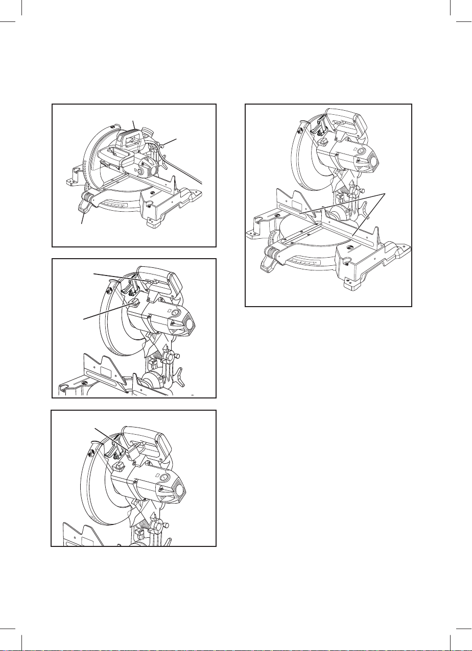
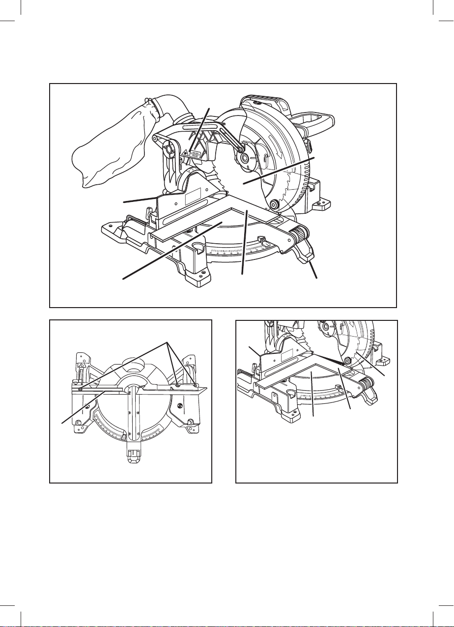
KNOW YOUR COMPOUND MITRE SAW
See Figure 1.
The safe use of this product requires an understanding of
the information on the tool and in this operator’s manual
as well as a knowledge of the project you are attempting.
Before use of this product, familiarize yourself with all
operating features and safety rules.
305 MM BLADE
A 305 mm blade is included with your compound mitre
saw. It will cut materials up to 200 mm wide, depending
upon the angle at which the cut is being made.
1800 W MOTOR
This saw has a powerful 1800 W motor with suffi cient
power to handle tough cutting jobs. It is made with all
ball bearings, and has externally accessible brushes for
ease of servicing.
BEVEL STOP ADJUSTMENT SCREWS
Bevel stop adjustment screws have been provided on
each side of the saw arm. These adjustment screws are
for making fi ne adjustments at 0° and 45°. The saw has
additional bevel stops at 3° and 48°.
3
Page 16

BEVEL LOCK KNOB
The bevel lock knob securely locks your compound mitre
saw at desired bevel angles.
BLADE WRENCH STORAGE
A blade wrench is packed with this saw. One end of the
wrench is a phillips screwdriver and the other end is a
hex key. Use the hex key end when installing or removing
blade and the phillips end when removing or loosening
screws. A storage area for the blade wrench is located
in the saw's base.
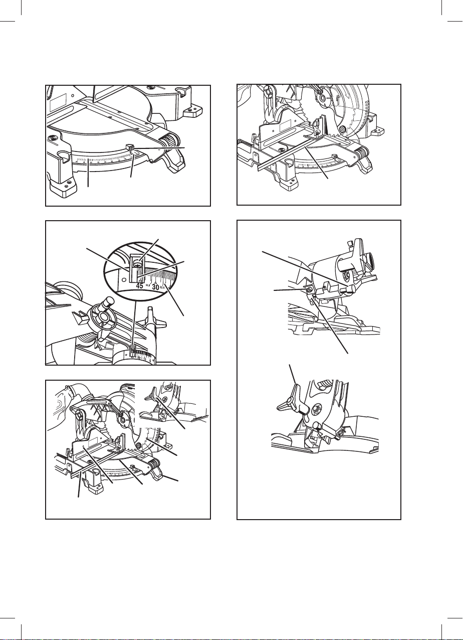
CARRYING HANDLE
See Figure 2.
For convenience when carrying or transporting the mitre
saw from one place to another, a carrying handle has
been provided on top of the saw arm. To transport, turn
off and unplug the saw, then lower the saw arm and lock
it in the down position. Lock saw arm by depressing the
lock pin.
ELECTRIC BRAKE
An electric brake has been provided to quickly stop blade
rotation after the switch is released.
LASER GUIDE
For more accurate cuts, a laser guide is included with
your mitre saw. When used properly, the laser guide
makes accurate, precision cutting simple and easy.
MITRE LOCK LEVER
The mitre lock lever securely locks the saw at the desired
mitre angle.
MITRE THUMBWHEEL
The mitre thumbwheel, when used with the mitre lock
lever lifted (unlocked), can release the mitre table from
pre-set index points. With the thumbwheel spun down
(and released), the mitre table moves freely to any
desired angle. With thumb on thumbwheel, push down
and hold to override (bypass) index points; release
thumbwheel when close to desired point and move the
lock lever into place with a click. With the thumbwheel
spun up, the mitre table will stop at each index point on
the mitre scale.
POSITIVE STOPS ON MITRE TABLE
Positive stops have been provided at 0°, 15°, 22.5°,
31.6°, and 45°. The 0°, 15°, 22.5°, 31.6°, and 45° positive
stops have been provided on both the left and right side
of the mitre table.
REPEAT-A-CUT™
See Figure 5.
The Repeat-A-Cut feature on both the left and right side
mitre fences can be used when making repetitive cuts.
Simply mark the fence with a pencil, make the desired
number of cut(s), then wipe the mark off with a soft cloth.
SELF-RETRACTING LOWER BLADE GUARD
The lower blade guard is made of shock-resistant, seethrough plastic that provides protection from each side of
the blade. It retracts over the upper blade guard as the
saw is lowered into the workpiece.
SPINDLE LOCK BUTTON
See Figure 3.
A spindle lock button has been provided for locking the
spindle which keeps the blade in the saw from rotating.
Depress and hold the lock button while installing,
changing, or removing blade only.
SLIDING MITRE FENCE
The sliding mitre fence on your compound mitre saw has
been provided to hold your workpiece securely against
when making all cuts; the left side is larger providing
additional support. It has a sliding feature for clearance
of the saw arm when making bevel or compound cuts.
Loosen the fence screw before attempting to slide the
mitre fence. Once the desired position of the mitre fence
is determined, tighten the fence screw to secure the
sliding fence.
SWITCH TRIGGER
See Figure 4.
To prevent unauthorized use of the compound mitre saw,
disconnect it from the power supply and lock the switch
in the off position. To lock the switch, install a padlock
(not included) through the hole in the switch trigger. A
lock with a long shackle up to 7.1 mm diameter may be
used. When the lock is installed and locked, the switch
is inoperable. Store the padlock key in another location.
DESCRIPTION
1. Upper blade guard
2. "D" handle
3. Switch trigger
4. Lower blade guard
5. Repeat-A-cut™
6. Throat plate
7. Saw base
8. Mitre thumbwheel
9. Mitre lock lever
10. Mitre scale
11. Work clamp
12. Mitre table
13. Lower guard lock lever
14. Fence screw
15. Blade wrench
16. Dust bag
17. Sliding mitre fence
18. Dust guide
19. Bevel stop pin
20. Bevel lock knob
21. Carrying handle
22. Lock pin
23. Spindle lock button
24. Blade
25. Trace holes at these locations for hole pattern
26. Mounting surface
4
Page 17

27. Exhaust port
28. Laser guide (089101611023)
29. Blade bolt
30. Blade bolt cover
31. Inner blade washer
32. Inner blade washer with double "D" fl ats
33. Screw
34. Broken line
35. Framing square
36. Socket head screw
37. Fence
38. Indicator screw
39. Scale indicator
40. Bevel scale
41. Combination square
42. Bevel stop
43. Bevel stop adjustment screw
44. Padlock (not included)
45. Indicator point
46. Laser warning label
47. Laser guide cover
48. Aperture
49. Key
50. Key slot
51. Laser guide support
52. Batteries
53. Negative (-)
ASSEMBLY
UNPACKING
This product requires assembly. Carefully lift saw from
the carton by the carrying handle and the saw base, and
place it on a level work surface.
NOTE: This tool is heavy. To avoid back injury, lift with
your legs, not your back, and get help when needed.
■ This saw has been shipped with the saw arm secured
in the down position. To release the saw arm, push
down on the top of the saw arm, cut the tie-wrap, and
pull out on the lock pin.
■ Lift the saw arm by the handle. Hand pressure should
remain on the saw arm to prevent sudden rise upon
release of the tie wrap.
■ Inspect the tool carefully to make sure no breakage or
damage occurred during shipping.
■ Do not discard the packing material until you have
carefully inspected and satisfactorily operated the
tool.
■ The saw is factory set for accurate cutting. After
assembling it, check for accuracy. If shipping has
influenced the settings, refer to specific procedures
explained in this manual.
WARNING
If any parts are damaged or missing, do not operate
this tool until the missing parts are replaced. Failure
to heed this warning could result in serious personal
injury.
WARNING
Do not attempt to modify this tool or create accessories
not recommended for use with this tool. Any such
alteration or modifi cation is misuse and could result
in a hazardous condition leading to possible serious
personal injury.
WARNING
Do not connect to power supply until assembly is
complete. Failure to comply could result in accidental
starting and possible serious personal injury.
WARNING
Do not start the compound mitre saw without checking
for interference between the blade and the mitre
fence. Damage could result to the blade if it strikes the
mitre fence during operation of the saw.
WARNING
Always make sure the compound mitre saw is securely
mounted to a workbench or an approved workstand.
Failure to heed this warning can result in serious
personal injury.
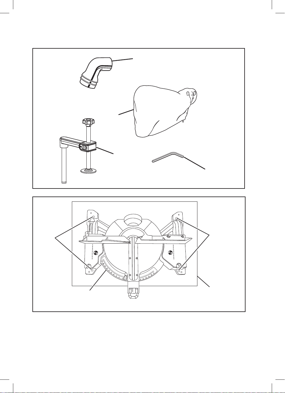
MOUNTING HOLES
See Figure 7.
The compound mitre saw should be mounted to a fi rm
supporting surface such as a workbench. Four bolt holes
have been provided in the saw base for this purpose.
Each of the four mounting holes should be bolted
securely using 9.5 mm machine bolts, lock washers,
and hex nuts (not included). Bolts should be of suffi cient
length to accommodate the saw base, lock washers,
hex nuts, and the thickness of the workbench. Tighten
all four bolts securely. The hole pattern for mounting
to a workbench. Carefully check the workbench after
mounting to make sure that no movement can occur
during use. If any tipping, sliding, or walking is noted,
secure the workbench to the fl oor before operating.
NOTE: Many of the illustrations in this manual show only
portions of the compound mitre saw. This is intentional
so that we can clearly show points being made in the
illustrations. Always secure all moving portions before
carrying the tool. Never operate the saw without all
guards securely in place and in good operating condition.
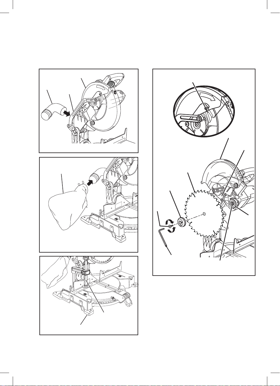
DUST GUIDE
See Figure 8.
Insert the dust guide inside the exhaust port in the upper
blade guard. Turn the guide so that the open end is
facing down or toward the rear of the saw.
DUST BAG
See Figure 9.
A dust bag is provided for use on this mitre saw. It fi ts
over the dust guide on the upper blade guard. To install
it, squeeze the two metal clips to open the mouth of the
5
Page 18

bag and slide it on the dust guide. Release the clips. The
metal ring in the bag should lock in between the grooves
on the dust guide.
To remove the dust bag for emptying, simply reverse the
above procedure.
WORK CLAMP
See Figure 10.
WARNING
In some operations, the work clamp assembly
may interfere with the operation of the blade guard
assembly. Always make sure there is no interference
with the blade guard prior to beginning any cutting
operation to reduce the risk of serious personal injury.
The work clamp provides greater control by clamping the
workpiece to the fence. It also prevents the workpiece
from creeping toward the saw blade. This is very helpful
when cutting compound mitres.
Depending on the cutting operation and the size of
the workpiece, it may be necessary to use a C-clamp
instead of the work clamp to secure the workpiece prior
to making the cut.
To install the work clamp:
1. Place the shaft of the work clamp in either hole on the
saw table base.
2. Rotate the knob on the work clamp to move it in or
out as needed.
NOTE: The work clamp has a quick release lever that
makes positioning of the work clamp effortless.
TO INSTALL THE BLADE
See Figure 11.
blade washer.
7. Wipe a drop of oil onto the inner blade washer and the
outer blade washer or laser guide where they contact
the blade.
WARNING
If inner blade washer has been removed, replace it
before placing blade on spindle. Failure to do so could
cause an accident since blade will not tighten properly.
8. Fit saw blade inside upper blade guard and onto
spindle. The blade teeth point downward at the front
of saw.
CAUTION
Always install the blade with the blade teeth and the
arrow printed on the side of the blade pointing down at
the front of the saw. The direction of blade rotation is
also stamped with an arrow on the upper blade guard.
9. Replace the laser guide. The double “D” fl ats on the
blade washers align with the fl ats on the spindle.
10. Depress spindle lock button and replace blade bolt.
NOTE: The blade bolt has left hand threads. Turn
blade bolt counterclockwise to tighten.
11. Tighten blade bolt securely.
12. Lower the blade guard and blade bolt cover.
13. Replace screw and tighten securely.
WARNING
Make sure the spindle lock button is not engaged
before reconnecting saw into power source. Never
engage spindle lock button when blade is rotating.
WARNING
A 305 mm blade is the maximum blade capacity of the
saw. Never use a blade that is too thick to allow outer
blade washer to engage with the fl ats on the spindle.
Larger blades will come in contact with the blade
guards, while thicker blades will prevent the blade bolt
from securing the blade on the spindle. Either of these
situations could result in a serious accident and can
cause serious personal injury.
NOTE: Check the blade carefully for cracks or
damage before operation. Replace cracked or
damaged blade immediately.
1. Unplug the saw.
2. Once blade has stopped, raise saw arm.
3. Loosen the screw (33). Rotate blade bolt cover up
and back to expose the blade bolt.
4. Depress the spindle lock button and rotate the blade
bolt until the spindle locks.
5. Using the wrench provided, loosen and remove the
blade bolt.
NOTE: The blade bolt has left hand threads. Turn
blade bolt clockwise to loosen.
6. Remove the laser guide. Do not remove the inner
6
DANGER
Laser radiation. Avoid direct eye contact with light
source.
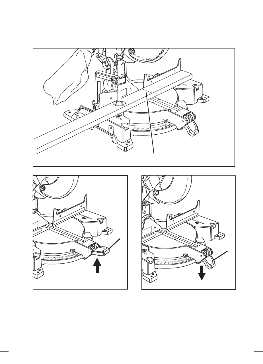
ALIGNING THE LASER GUIDE LINE
See Figure 12.
The laser guide will generate a colored line on the work
surface when the blade is spinning. The laser line will
appear as a broken line on the workpiece when the blade
assembly is in the uppermost position and the motor
switch is activated. This broken line will let you see your
mark and your laser guide line at the same time, and will
assist you in lining up your mark for more accurate cutting
of the workpiece.
To cut your mark:
Using a sharp pencil, mark a line on the workpiece.
With the saw blade in the uppermost position, align
the laser line with your mark. Once both lines are in
alignment, do not move the workpiece until after you
have fi nished cutting.
NOTE: As the saw blade assembly is lowered toward the
workpiece, the broken line will become solid. The solid
Page 19

line will drift away from the mark as the saw blade gets
closer to the workpiece. This is normal. The blade will
cut on the mark. Never attempt to move the workpiece
while making a cut. Always keep hands outside the “NO
HANDS ZONE”.
Make several practice cuts on different styles and
thickness of material.
To remove your mark:
Position the laser line near the left edge of your mark on
the work surface in order to remove the mark.
To leave your mark:
Position the laser line near the right edge of your mark on
the work surface in order to leave the mark.
After you have become familiar with using the laser
guide, you will be able to remove, cut, or leave your mark
on the work surface. Practice will teach you the correct
position for aligning the laser line with your mark.
ADJUSTING THE MITRE LOCK LEVER
See Figures 13 - 14.
Prior to squaring the saw blade to the fence, check and
align the mitre lock lever. The blade must be set at an
“unindexed” mitre position other than 0°, 15°, 22.5°,
31.6°, and 45° to test. In the “locked” position, the action
of pushing the mitre lock lever down should feel tight and
secure. Considerable effort should be required to move
the mitre table. If the table moves easily when in the
“locked” position, an adjustment of the mitre lock lever
is required.
To adjust:
1. Unplug the saw.
2. Lift the mitre lock lever to unlock.
3. Locate the set screw under the mitre lock lever.
4. Using a hex key, adjust the set screw until the proper
amount of tension in the lock lever is attained.
5. Once all adjustments have been made, push the
mitre lock lever down to relock the mitre table.
SQUARING THE SAW BLADE TO THE FENCE
See Figures 15 - 19.
1. Unplug the saw.
2. Pull the saw arm all the way down and lock in
transport position.
3. Lift the mitre lock lever.
4. Rotate the mitre table until the pointer on the mitre
scale is positioned at 0°.
5. Lock the mitre lock lever by pushing it down.
6. Remove the sliding mitre fence by loosening the
fence screw and lifting the sliding mitre fence off the
saw.
7. Lay a framing square fl at on the mitre table. Place
one leg of the square against the fence. Slide the
other leg of the square against the fl at part of saw
blade.
NOTE: Make sure that the square contacts the flat
part of the saw blade, not the blade teeth.
8. The edge of the square and the saw blade should
be parallel.
9. If the front or back edge of the saw blade angles away
from the square, adjustments are needed.
10. Loosen the socket head screws that secure the fence
to the mitre table. See Figure 16.
11. Rotate the fence left or right until the saw blade is
parallel with the square.
12. Retighten the socket head screws securely and
recheck the blade-to-fence alignment.
Your saw has several scale indicators. After squaring
adjustments have been made, it may be necessary to
loosen the indicator screws and reset them to zero. See
Figures 18 - 19.
SQUARING THE BLADE TO THE MITRE TABLE
See Figures 20 - 22.
1. Unplug the saw.
2. Pull the saw arm all the way down and lock in
transport position.
3. Lift the mitre lock lever.
4. Rotate the mitre table until the pointer on the mitre
scale is positioned at 0°.
5. Lock the mitre lock lever by pushing it down.
6. Loosen bevel lock knob and set saw arm at 0° bevel
(blade set 90° to mitre table). Tighten bevel lock knob.
7. Place a combination square against the mitre table
and the fl at part of saw blade.
NOTE: Make sure that the square contacts the flat
part of the saw blade, not the blade teeth.
8. Rotate the blade by hand and check the blade-totable alignment at several points.
9. The edge of the square and the saw blade should
be parallel.
10. If the top or bottom of the saw blade angles away
from the square, adjustments are needed.
11. Loosen the bevel lock knob.
12. Using the blade wrench, loosen the bevel stop
adjustment screw and slide the bevel stop left or right
as needed to bring the saw blade into alignment with
the square. Retighten bevel stop adjustment screw.
See Figure 22.
13. Retighten bevel lock knob. Recheck blade-to-table
alignment.
NOTE: The above procedure can be used to check
blade squareness of the saw blade to the mitre table
at both 0° and 45° angles.
Your saw has several scale indicators. After squaring
adjustments have been made, it may be necessary to
loosen the indicators screws and reset them to zero. See
Figures 18 - 19.
PIVOT ADJUSTMENTS
NOTE: These adjustments were made at the factory and
normally do not require readjustment.
TRAVEL PIVOT ADJUSTMENT
The saw arm should rise completely to the up position
by itself.
If the saw arm does not raise by itself or if there is play
in the pivot joints, have saw repaired at your nearest
authorized service center.
7
Page 20

BEVEL PIVOT ADJUSTMENT
The compound mitre saw should bevel easily by
loosening the bevel lock knob and tilting the saw arm to
the left.
If movement is tight or if there is play in the pivot, have
saw repaired at your nearest authorized service center.
OPERATION
WARNING
Do not allow familiarity with tools to make you careless.
Remember that a careless fraction of a second is
suffi cient to infl ict severe injury.
WARNING
Always wear safety goggles or safety glasses with
side shields when operating tools. Failure to do so
could result in objects being thrown into your eyes
resulting in possible serious injury.
WARNING
Do not start your compound mitre saw without
checking for interference between the blade and the
mitre fence. Damage could result to the blade if it
strikes the mitre fence during operation of the saw.
Failure to heed this warning can also result in serious
personal injury.
CUTTING WITH YOUR COMPOUND MITRE SAW
WARNING
When using a work clamp or C-clamp to secure
your workpiece, clamp workpiece on one side of the
blade only. The workpiece must remain free on one
side of the blade to prevent the blade from binding in
workpiece. The workpiece binding the blade will cause
motor stalling and kickback. This situation could cause
an accident resulting in possible serious personal
injury.
WARNING
Do not use any attachments or accessories not
recommended by the manufacturer of this tool. The
use of attachments or accessories not recommended
can result in serious personal injury.
APPLICATIONS
This product has been designed only for the purposes
listed below:
● Cross cutting wood and plastic.
● Cross cutting mitres, joints, etc. for picture frames,
moldings, door casings, and fine joinery.
NOTE: The blade provided is fi ne for most wood cutting
operations, but for fi ne joinery cuts or cutting plastic, use
one of the accessory blades available from the AEG
dealer.
WARNING
Before starting any cutting operation, clamp or bolt
your mitre saw to a workbench. Never operate your
mitre saw on the fl oor or in a crouched position. Failure
to heed this warning can result in serious personal
injury.
WARNING
To avoid serious personal injury, keep your hands
outside the no hands zone. Never perform any cutting
operation freehand (without holding workpiece against
the fence). The blade could grab the workpiece if it
slips or twists.
WARNING
To avoid serious personal injury, always tighten the
mitre lock handle securely before making a cut. Failure
to do so could result in movement of the control arm or
mitre table while making a cut.
MITRE THUMBWHEEL
The mitre thumbwheel, when used with the mitre lock
lever lifted (unlocked), can release the mitre table from
pre-set index points.
To align with mitre scale:
1. Lift the mitre lock lever to unlock.
2. Rotate and hold thumbwheel so that the yellow dot on
the thumbwheel aligns with indicator point (white dot)
on the mitre lock lever to override index points.
3. When close to desired angle, release the thumbwheel.
NOTE: When the orange dot on the thumbwheel
clicks into place (aligned with the indicator point), the
mitre table is locked into a preset index point.
4. Push the mitre lock lever down to lock the mitre table.
5. To bypass preset index points:
● Lift the mitre lock lever to unlock.
● Rotate the thumbwheel so that the white dot on
the thumbwheel aligns with the indicator point
(white dot) on the mitre lock lever.
TO MITRE CUT/CROSS CUT
See Figures 23 - 24.
A cross cut is made by cutting across the grain of the
workpiece. A straight cross cut is made with the mitre
table set at the 0° position. Mitre cross cuts are made with
the mitre table set at some angle other than zero.
1. Pull out the lock pin and lift saw arm to its full height.
2. Lift the mitre lock lever to unlock. Rotate the mitre
table until the pointer aligns with the desired angle on
the mitre scale.
8
Page 21

NOTE: You can quickly locate 0°, 15°, 22.5°, 31.6°,
and 45° left or right by spinning the mitre thumbwheel
up. The lock plate will seat itself in one of the positive
stop notches, located in the mitre table base.
3. Push the mitre lock lever down to lock the mitre table.
4. Place the workpiece fl at on the mitre table with one
edge securely against the fence. If the board is
warped, place the convex side against the fence. If
the concave edge of a board is placed against the
fence, the board could collapse on the blade at the
end of the cut, jamming the blade. See Figures 30
- 31.
5. When cutting long pieces of lumber or molding,
support the opposite end of the stock with a roller
stand or with a work surface level with the saw table.
See Figure 27.
6. Align cutting line on the workpiece with the edge of
saw blade.
7. Grasp the stock fi rmly with one hand and secure it
against the fence. Use the work clamp or a C-clamp
to secure the workpiece when possible.
8. Before turning on the saw, perform a dry run of the
cutting operation to make sure that no problems will
occur when the cut is made.
9. Grasp the saw handle fi rmly. Depress the switch lock
with thumb then squeeze the switch trigger. Allow
several seconds for the blade to reach maximum
speed.
10. Slowly lower the blade into and through the workpiece.
11. Release the switch trigger and allow the saw blade to
stop rotating before raising the blade out of workpiece
and removing the workpiece from the mitre table.
TO BEVEL CUT
See Figure 25.
A bevel cut is made by cutting across the grain of the
workpiece with the blade angled to the workpiece. A
straight bevel cut is made with the mitre table set at
the zero degree position and the blade set at an angle
between -3° and 48°.
NOTE: It may be necessary to adjust or remove the
sliding mitre fence to insure proper clearance prior to
making the cut.
1. Pull out the lock pin and lift saw arm to its full height.
2. Lift the mitre lock lever to unlock. Rotate the mitre
table until the pointer aligns with zero on the mitre
scale.
3. Push the mitre lock lever down to lock the mitre table.
4. Loosen the bevel lock knob and move the saw arm to
the left to the desired bevel angle.
5. Once the saw arm has been set at the desired angle,
securely tighten the bevel lock knob.
6. Place the workpiece fl at on the mitre table with one
edge securely against the fence. If the board is
warped, place the convex side against the fence. If
the concave edge of a board is placed against the
fence, the board could collapse on the blade at the
end of the cut, jamming the blade. See Figures 30
- 31.
7. When cutting long pieces of lumber or molding,
support the opposite end of the stock with a roller
stand or with a work surface level with the saw table.
See Figure 27.
8. Align the cutting line on the workpiece with the edge
of saw blade.
9. Grasp the stock fi rmly with one hand and secure it
against the fence. Use the work clamp or a C-clamp
to secure the workpiece when possible.
10. Before turning on the saw, perform a dry run of the
cutting operation to make sure that no problems will
occur when the cut is made.
11. Grasp the saw handle fi rmly. Depress the switch lock
with thumb then squeeze the switch trigger. Allow
several seconds for the blade to reach maximum
speed.
12. Slowly lower the blade into and through the workpiece.
13. Release the switch trigger and allow the saw blade to
stop rotating before raising the blade out of workpiece
and removing the workpiece from the mitre table.
TO COMPOUND MITRE CUT
See Figure 28.
A compound mitre cut is a cut made using a mitre angle
and a bevel angle at the same time. This type of cut is
used to make picture frames, cut molding, make boxes
with sloping sides, and for certain roof framing cuts.
To make this type of cut the control arm on the mitre table
must be rotated to the correct angle and the saw arm
must be tilted to the correct bevel angle. Care should
always be taken when making compound mitre setups
due to the interaction of the two angle settings.
Adjustments of mitre and bevel settings are
interdependent with one another. Each time you adjust
the mitre setting you change the effect of the bevel
setting. Also, each time you adjust the bevel setting you
change the effect of the mitre setting.
It may take several settings to obtain the desired cut. The
fi rst angle setting should be checked after setting the
second angle, since adjusting the second angle affects
the fi rst.
Once the two correct settings for a particular cut have
been obtained, always make a test cut in scrap material
before making a fi nish cut in good material.
NOTE: It may be necessary to adjust or remove the
sliding mitre fence to insure proper clearance prior to
making the cut.
1. Raise saw arm to its full height.
2. Lift the mitre lock lever to unlock. Rotate the mitre
table until the pointer aligns with the desired angle on
the mitre scale.
NOTE: You can quickly locate 0°, 15°, 22.5°, 31.6°,
and 45° left or right by spinning the mitre thumbwheel
up. The lock plate will seat itself in one of the positive
stop notches, located in the mitre table base.
3. Push the mitre lock lever down to lock the mitre table.
4. Loosen the bevel lock knob and move the saw arm to
the left to the desired bevel angle.
5. Once the saw arm has been set at the desired angle,
securely tighten the bevel lock knob.
6. Place the workpiece fl at on the mitre table with one
edge securely against the fence. If the board is
warped, place the convex side against the fence. If
the concave edge of a board is placed against the
9
Page 22

fence, the board could collapse on the blade at the
end of the cut, jamming the blade. See Figures 30
- 31.
7. When cutting long pieces of lumber or molding,
support the opposite end of the stock with a roller
stand or with a work surface level with the saw table.
See Figure 27.
8. Align the cutting line on the workpiece with the edge
of saw blade.
9. Grasp the stock fi rmly with one hand and secure it
against the fence. Use the work clamp or a C-clamp
to secure the workpiece when possible.
10. Before turning on the saw, perform a dry run of the
cutting operation to make sure that no problems will
occur when the cut is made.
11. Make a test cut in scrap material.
12. Grasp the saw handle fi rmly. Depress the switch lock
with thumb then squeeze the switch trigger. Allow
several seconds for the blade to reach maximum
speed.
13. Slowly lower the blade into and through the workpiece.
14. Release the switch trigger and allow the saw blade to
stop rotating before raising the blade out of workpiece
and removing the workpiece from the mitre table.
SUPPORTING LONG WORKPIECES
See Figures 27 - 28.
Long workpieces need extra supports. Supports should
be placed along the workpiece so it does not sag. The
support should let the workpiece lay fl at on the base of
the saw and mitre table during the cutting operation. Use
the work clamp to secure the workpiece.
NOTE: When making a compound mitre cut, it may be
necessary to adjust or remove the sliding mitre fence to
insure proper clearance prior to making the cut.
CLAMPING WIDE WORKPIECES
See Figure 29.
When cutting wide workpieces, boards should be
clamped with the work clamp.
CUTTING COMPOUND MITRES
To aid in making the correct settings, the compound angle
setting chart below has been provided. Since compound
cuts are the most diffi cult to accurately obtain, trial cuts
should be made in scrap material, and much thought and
planning made, prior to making your required cut.
CUTTING WARPED MATERIAL
See Figures 30 - 31.
When cutting warped material, always make sure it is
positioned on the mitre table with the convex side against
the fence.
If the warped material is positioned the wrong way, it will
pinch the blade near the completion of the cut.
ADJUSTMENTS
WARNING
Before performing any adjustment, make sure the tool
is unplugged from the power supply. Failure to heed
this warning could result in serious personal injury.
MAINTENANCE
CHANGING THE BATTERIES
See Figure 32.
1. Unplug your saw.
WARNING
Failure to unplug your saw could result in accidental
starting causing possible serious personal injury.
2. Remove the laser guide from the saw. Lay laser guide
on a fl at surface with the two phillips screws facing
upward.
3. Remove the screws and separate the laser guide
cover from the laser guide support.
4. Remove the three button cell batteries using a nonconductive device such as a toothpick.
NOTE: Replace the batteries with button cell batteries
that have a rating of 1.5 volt.
When replacing the batteries, the laser guide should
be thoroughly cleaned. Use a soft paintbrush or similar
device, to remove all sawdust and debris.
Do not attempt to activate the laser.
The laser is activated by means of a centrifugal switch
only while the saw motor is running and the laser guide is
mounted on the saw.
After cleaning laser guide and replacing batteries, secure
laser guide cover to laser guide support using the two
phillips head screws. For proper assembly, be sure to
align the key on the laser guide cover with the key slot in
the laser guide support. Tighten screws securely.
NOTE: Aperture in laser guide cover must be aligned
with aperture in laser guide support.
CAUTION
Use of controls or adjustments or performance of
procedures other than those specifi ed herein may
result in hazardous radiation exposure.
WARNING
When servicing, use only identical replacement parts.
Use of any other part may create a hazard or cause
product damage.
WARNING
To avoid a kickback and to avoid serious personal
injury, never position the concave edge of bowed or
warped material against the fence.
10
WARNING
Always wear safety goggles or safety glasses with side
shields during power tool operation or when blowing
dust. If operation is dusty, also wear a dust mask.
Page 23

GENERAL MAINTENANCE
Avoid using solvents when cleaning plastic parts. Most
plastics are susceptible to damage from various types of
commercial solvents and may be damaged by their use.
Use clean cloths to remove dirt, carbon dust, etc.
WARNING
Do not at any time let brake fl uids, gasoline, petroleum-
based products, penetrating oils, etc., come in contact
with plastic parts. They contain chemicals that can
damage, weaken, or destroy plastic.
min
no
No-load speed
-
1
Revolutions or reciprocations per minute
CE Conformity
Please read the instructions carefully
before starting the machine.
LUBRICATION
All of the bearings in this tool are lubricated with a
suffi cient amount of high grade lubricant for the life of
the unit under normal operating conditions. Therefore, no
further lubrication is required.
WARNING
To ensure safety and reliability, all repairs should
be performed by a qualifi ed service technician at an
authorized service center to avoid risk of personal
injury.
Some areas will require infrequent lubrications. You will
need to apply:
Automotive oil directly to the slide bars.
Light oil or a pressurized light spray oil to the arm pivot
shaft.
Light oil or a pressurized light spray oil to the torsion
spring.
CAUTION
Use of controls or adjustments or performance of
procedures other than those specifi ed herein may
result in hazardous radiation exposure.
ENVIRONMENTAL PROTECTION
Recycle raw materials instead of disposing
of as waste. The machine, accessories
and packaging should be sorted for
environmental-friendly recycling.
SYMBOL
Safety Alert
V Volts
Hz
Hertz
Alternating Current
Wear ear protection
Wear eye protection
Danger! Sharp blade.
Double insulation
Waste electrical products should not
be disposed of with household waste.
Please recycle where facilities exist.
Check with your Local Authority or
retailer for recycling advice.
VIBRATION
The vibration emission level given in the information sheet
has been measured in accordance with a standardised
test given in EN 61029 and may be used to compare
one tool with another. It may be used for a preliminary
assessment of exposure.
WARNING
The declared vibration emission level represents the
main applications of the tool. However, if the tool is used
for different applications, with different accessories or
poorly maintained, the vibration emission may differ.
This may signifi cantly increase the exposure level over
the total working period.
An estimation of the level of exposure to vibration should
also take into account the times when the tool is switched
off or when it is running but not actually doing the job.
This may signifi cantly reduce the exposure level over the
total working period. Identify additional safety measures
to protect the operator from the effects of vibration such
as: maintain the tool and the accessories, keep the hands
warm, organization of work patterns.
W
Watts
11
Page 24

 Loading...