

—
ABB GENERAL PURPOSE DRIVES
ACS580-01 drives
(0.75 to 250 kW, 1.0 to 350 hp)
Hardware manual

Related documents are listed on page 27.
Hardware manual
ACS580-01 drives
(0.75 to 250 kW, 1.0 to 350 hp)
Table of contents
1. Safety instructions
4. Mechanical installation
2019 ABB Oy. All Rights Reserved.
6. Electrical installation –
IEC
7. Electrical installation –
North America
3AXD50000044794 Rev B
EFFECTIVE: 2019-03-13
IEC
UL
NEC
EN


Table of contents 5
Table of contents
1. Safety instructions
Contents of this chapter . . . . . . . . . . . . . . . . . . . . . . . . . . . . . . . . . . . . . . . . . . . . . . . . . . . . . . 15
Use of warnings and notes in this manual . . . . . . . . . . . . . . . . . . . . . . . . . . . . . . . . . . . . . . . . 15
General safety in installation, start-up and maintenance . . . . . . . . . . . . . . . . . . . . . . . . . . . . . 16
Electrical safety in installation, start-up and maintenance . . . . . . . . . . . . . . . . . . . . . . . . . . . . 18
Precautions before electrical work . . . . . . . . . . . . . . . . . . . . . . . . . . . . . . . . . . . . . . . . . . 18
Additional instructions and notes . . . . . . . . . . . . . . . . . . . . . . . . . . . . . . . . . . . . . . . . . . . 19
Grounding . . . . . . . . . . . . . . . . . . . . . . . . . . . . . . . . . . . . . . . . . . . . . . . . . . . . . . . . . . . . . 20
Additional instructions for permanent magnet motor drives . . . . . . . . . . . . . . . . . . . . . . . . . . 22
Safety in installation, start-up and maintenance . . . . . . . . . . . . . . . . . . . . . . . . . . . . . . . . 22
General safety in operation . . . . . . . . . . . . . . . . . . . . . . . . . . . . . . . . . . . . . . . . . . . . . . . . . . . 23
2. Introduction to the manual
Contents of this chapter . . . . . . . . . . . . . . . . . . . . . . . . . . . . . . . . . . . . . . . . . . . . . . . . . . . . . . 25
Applicability . . . . . . . . . . . . . . . . . . . . . . . . . . . . . . . . . . . . . . . . . . . . . . . . . . . . . . . . . . . . . . . 25
Target audience . . . . . . . . . . . . . . . . . . . . . . . . . . . . . . . . . . . . . . . . . . . . . . . . . . . . . . . . . . . . 25
Purpose of the manual . . . . . . . . . . . . . . . . . . . . . . . . . . . . . . . . . . . . . . . . . . . . . . . . . . . . . . 25
Contents of this manual . . . . . . . . . . . . . . . . . . . . . . . . . . . . . . . . . . . . . . . . . . . . . . . . . . . . . . 26
Categorization by frame (size) . . . . . . . . . . . . . . . . . . . . . . . . . . . . . . . . . . . . . . . . . . . . . . . . . 27
Related documents . . . . . . . . . . . . . . . . . . . . . . . . . . . . . . . . . . . . . . . . . . . . . . . . . . . . . . . . . 27
Quick installation and commissioning flowchart . . . . . . . . . . . . . . . . . . . . . . . . . . . . . . . . . . . 29
Terms and abbreviations . . . . . . . . . . . . . . . . . . . . . . . . . . . . . . . . . . . . . . . . . . . . . . . . . . . . . 31
Safety
3. Operation principle and hardware description
Contents of this chapter . . . . . . . . . . . . . . . . . . . . . . . . . . . . . . . . . . . . . . . . . . . . . . . . . . . . . . 35
Operation principle . . . . . . . . . . . . . . . . . . . . . . . . . . . . . . . . . . . . . . . . . . . . . . . . . . . . . . . . . 36
Layout . . . . . . . . . . . . . . . . . . . . . . . . . . . . . . . . . . . . . . . . . . . . . . . . . . . . . . . . . . . . . . . . . . . 37
Overview of power and control connections . . . . . . . . . . . . . . . . . . . . . . . . . . . . . . . . . . . . . . 43
External control connection terminals, frames R1…R5 . . . . . . . . . . . . . . . . . . . . . . . . . . 44
External control connection terminals, frames R6…R9 . . . . . . . . . . . . . . . . . . . . . . . . . . 45
Control panel . . . . . . . . . . . . . . . . . . . . . . . . . . . . . . . . . . . . . . . . . . . . . . . . . . . . . . . . . . . . . . 46
Control panel door mounting kits . . . . . . . . . . . . . . . . . . . . . . . . . . . . . . . . . . . . . . . . . . . 47
Type designation label . . . . . . . . . . . . . . . . . . . . . . . . . . . . . . . . . . . . . . . . . . . . . . . . . . . . . . . 47
Type designation key . . . . . . . . . . . . . . . . . . . . . . . . . . . . . . . . . . . . . . . . . . . . . . . . . . . . . . . . 49
4. Mechanical installation
Contents of this chapter . . . . . . . . . . . . . . . . . . . . . . . . . . . . . . . . . . . . . . . . . . . . . . . . . . . . . . 53
Safety . . . . . . . . . . . . . . . . . . . . . . . . . . . . . . . . . . . . . . . . . . . . . . . . . . . . . . . . . . . . . . . . . . . 53
Checking the installation site . . . . . . . . . . . . . . . . . . . . . . . . . . . . . . . . . . . . . . . . . . . . . . . . . . 54
Required tools . . . . . . . . . . . . . . . . . . . . . . . . . . . . . . . . . . . . . . . . . . . . . . . . . . . . . . . . . . . . . 58
Moving the drive . . . . . . . . . . . . . . . . . . . . . . . . . . . . . . . . . . . . . . . . . . . . . . . . . . . . . . . . . . . 58
Unpacking and examining delivery, frames R1 and R2 . . . . . . . . . . . . . . . . . . . . . . . . . . . . . . 59

6 Table of contents
Frames R1 and R2 cable box (IP21, UL Type 1) . . . . . . . . . . . . . . . . . . . . . . . . . . . . . . . 61
Unpacking and examining delivery, frame R3 . . . . . . . . . . . . . . . . . . . . . . . . . . . . . . . . . . . . 62
Unpacking and examining delivery, frame R4 . . . . . . . . . . . . . . . . . . . . . . . . . . . . . . . . . . . . 64
Unpacking and examining delivery, frame R5 . . . . . . . . . . . . . . . . . . . . . . . . . . . . . . . . . . . . 66
Frame R5 cable box (IP21, UL Type 1) . . . . . . . . . . . . . . . . . . . . . . . . . . . . . . . . . . . . . . 67
Unpacking and examining delivery, frames R6…R9 . . . . . . . . . . . . . . . . . . . . . . . . . . . . . . . 68
Frame R6 cable box (IP21, UL Type 1) . . . . . . . . . . . . . . . . . . . . . . . . . . . . . . . . . . . . . . 70
Frame R7 cable box (IP21, UL Type 1) . . . . . . . . . . . . . . . . . . . . . . . . . . . . . . . . . . . . . . 71
Frame R8 cable box (IP21, UL Type 1) . . . . . . . . . . . . . . . . . . . . . . . . . . . . . . . . . . . . . . 72
Frame R9 cable box (IP21, UL Type 1) . . . . . . . . . . . . . . . . . . . . . . . . . . . . . . . . . . . . . . 73
Installing the drive . . . . . . . . . . . . . . . . . . . . . . . . . . . . . . . . . . . . . . . . . . . . . . . . . . . . . . . . . 74
Installing the drive vertically, frames R1…R4 . . . . . . . . . . . . . . . . . . . . . . . . . . . . . . . . . 74
Install the cable box, frames R1…R2 . . . . . . . . . . . . . . . . . . . . . . . . . . . . . . . . . . . . . . . . 76
Installing the drive vertically, frame R5 . . . . . . . . . . . . . . . . . . . . . . . . . . . . . . . . . . . . . . 77
Installing the drive vertically, frames R6…R9 . . . . . . . . . . . . . . . . . . . . . . . . . . . . . . . . . 80
Installing the drive vertically side by side . . . . . . . . . . . . . . . . . . . . . . . . . . . . . . . . . . . . . 81
Installing the drive horizontally, frames R1…R5 . . . . . . . . . . . . . . . . . . . . . . . . . . . . . . . 82
Flange mounting . . . . . . . . . . . . . . . . . . . . . . . . . . . . . . . . . . . . . . . . . . . . . . . . . . . . . . . . . . . 82
5. Guidelines for planning the electrical installation
Contents of this chapter . . . . . . . . . . . . . . . . . . . . . . . . . . . . . . . . . . . . . . . . . . . . . . . . . . . . . 83
Limitation of liability . . . . . . . . . . . . . . . . . . . . . . . . . . . . . . . . . . . . . . . . . . . . . . . . . . . . . . . . 83
Selecting the supply disconnecting device . . . . . . . . . . . . . . . . . . . . . . . . . . . . . . . . . . . . . . . 83
European Union . . . . . . . . . . . . . . . . . . . . . . . . . . . . . . . . . . . . . . . . . . . . . . . . . . . . . . . . 84
North America . . . . . . . . . . . . . . . . . . . . . . . . . . . . . . . . . . . . . . . . . . . . . . . . . . . . . . . . . 84
Other regions . . . . . . . . . . . . . . . . . . . . . . . . . . . . . . . . . . . . . . . . . . . . . . . . . . . . . . . . . . 84
Checking the compatibility of the motor and drive . . . . . . . . . . . . . . . . . . . . . . . . . . . . . . . . . 85
Protecting the motor insulation and bearings . . . . . . . . . . . . . . . . . . . . . . . . . . . . . . . . . . 85
Requirements table . . . . . . . . . . . . . . . . . . . . . . . . . . . . . . . . . . . . . . . . . . . . . . . . . . . . . 86
Selecting the power cables . . . . . . . . . . . . . . . . . . . . . . . . . . . . . . . . . . . . . . . . . . . . . . . . . . 91
General guidelines, IEC and North America . . . . . . . . . . . . . . . . . . . . . . . . . . . . . . . . . . 91
Power cable types . . . . . . . . . . . . . . . . . . . . . . . . . . . . . . . . . . . . . . . . . . . . . . . . . . . . . . 93
Additional guidelines, North America . . . . . . . . . . . . . . . . . . . . . . . . . . . . . . . . . . . . . . . . 95
Conductor type, IEC and North America . . . . . . . . . . . . . . . . . . . . . . . . . . . . . . . . . . . . . 97
Power cable shield, IEC and North America . . . . . . . . . . . . . . . . . . . . . . . . . . . . . . . . . . 97
Typical power cable sizes, IEC . . . . . . . . . . . . . . . . . . . . . . . . . . . . . . . . . . . . . . . . . . . . 99
Typical power cable sizes, UL/NEC . . . . . . . . . . . . . . . . . . . . . . . . . . . . . . . . . . . . . . . . 101
Armored cable / shielded power cable, IEC and North America . . . . . . . . . . . . . . . . . . 101
Selecting the control cables, IEC and North America . . . . . . . . . . . . . . . . . . . . . . . . . . . . . . 102
Shielding . . . . . . . . . . . . . . . . . . . . . . . . . . . . . . . . . . . . . . . . . . . . . . . . . . . . . . . . . . . . 102
Signals in separate cables . . . . . . . . . . . . . . . . . . . . . . . . . . . . . . . . . . . . . . . . . . . . . . . 102
Signals allowed to be run in the same cable . . . . . . . . . . . . . . . . . . . . . . . . . . . . . . . . . 102
Relay cable . . . . . . . . . . . . . . . . . . . . . . . . . . . . . . . . . . . . . . . . . . . . . . . . . . . . . . . . . . 102
Control panel cable . . . . . . . . . . . . . . . . . . . . . . . . . . . . . . . . . . . . . . . . . . . . . . . . . . . . 102
Drive composer PC tool cable . . . . . . . . . . . . . . . . . . . . . . . . . . . . . . . . . . . . . . . . . . . . 103
FPBA-01 PROFIBUS DP adapter module connectors . . . . . . . . . . . . . . . . . . . . . . . . . . 103
Routing the cables . . . . . . . . . . . . . . . . . . . . . . . . . . . . . . . . . . . . . . . . . . . . . . . . . . . . . . . . 104
General guidelines, IEC . . . . . . . . . . . . . . . . . . . . . . . . . . . . . . . . . . . . . . . . . . . . . . . . . 104
General guidelines, North America . . . . . . . . . . . . . . . . . . . . . . . . . . . . . . . . . . . . . . . . 105
Continuous motor cable shield or enclosure for equipment on the motor cable . . . . . . 106

Table of contents 7
Separate control cable ducts, IEC and North America . . . . . . . . . . . . . . . . . . . . . . . . . . 106
Implementing short-circuit and thermal overload protection . . . . . . . . . . . . . . . . . . . . . . . . . 107
Protecting the drive and input power cable in short-circuits . . . . . . . . . . . . . . . . . . . . . . 107
Protecting the motor and motor cable in short-circuits . . . . . . . . . . . . . . . . . . . . . . . . . . 107
Protecting the drive and the input power and motor cables against thermal overload . . 108
Protecting the motor against thermal overload . . . . . . . . . . . . . . . . . . . . . . . . . . . . . . . . 108
Protecting the motor against overload without thermal model or temperature sensors . 108
Implementing a ground fault detection function . . . . . . . . . . . . . . . . . . . . . . . . . . . . . . . . . . . 109
Residual current device compatibility . . . . . . . . . . . . . . . . . . . . . . . . . . . . . . . . . . . . . . . 109
Implementing the Emergency stop function . . . . . . . . . . . . . . . . . . . . . . . . . . . . . . . . . . . . . 109
Implementing the Safe torque off function . . . . . . . . . . . . . . . . . . . . . . . . . . . . . . . . . . . . . . . 109
Implementing the ATEX-certified Safe motor disconnection function (option +Q971) . . . . . 109
Using a safety switch between the drive and the motor . . . . . . . . . . . . . . . . . . . . . . . . . . . . 109
Using a contactor between the drive and the motor . . . . . . . . . . . . . . . . . . . . . . . . . . . . . . . 110
Implementing a bypass connection . . . . . . . . . . . . . . . . . . . . . . . . . . . . . . . . . . . . . . . . . . . . 110
Example bypass connection . . . . . . . . . . . . . . . . . . . . . . . . . . . . . . . . . . . . . . . . . . . . . . 111
Implementing the undervoltage control (power-loss ride-through) . . . . . . . . . . . . . . . . . . . . 112
Protecting the contacts of relay outputs . . . . . . . . . . . . . . . . . . . . . . . . . . . . . . . . . . . . . . . . 112
Limiting relay output maximum voltages at high installation altitudes . . . . . . . . . . . . . . . . . . 113
Implementing a motor temperature sensor connection . . . . . . . . . . . . . . . . . . . . . . . . . . . . . 114
6. Electrical installation – IEC
Contents of this chapter . . . . . . . . . . . . . . . . . . . . . . . . . . . . . . . . . . . . . . . . . . . . . . . . . . . . . 117
Warnings . . . . . . . . . . . . . . . . . . . . . . . . . . . . . . . . . . . . . . . . . . . . . . . . . . . . . . . . . . . . . . . . 117
Required tools . . . . . . . . . . . . . . . . . . . . . . . . . . . . . . . . . . . . . . . . . . . . . . . . . . . . . . . . . . . . 117
Checking the insulation of the assembly . . . . . . . . . . . . . . . . . . . . . . . . . . . . . . . . . . . . . . . . 118
Drive . . . . . . . . . . . . . . . . . . . . . . . . . . . . . . . . . . . . . . . . . . . . . . . . . . . . . . . . . . . . . . . . 118
Input power cable . . . . . . . . . . . . . . . . . . . . . . . . . . . . . . . . . . . . . . . . . . . . . . . . . . . . . . 118
Motor and motor cable . . . . . . . . . . . . . . . . . . . . . . . . . . . . . . . . . . . . . . . . . . . . . . . . . . 118
Brake resistor assembly for R1…R3 . . . . . . . . . . . . . . . . . . . . . . . . . . . . . . . . . . . . . . . . 119
Checking the compatibility with IT (ungrounded), corner-grounded delta, midpoint-grounded
delta and TT systems . . . . . . . . . . . . . . . . . . . . . . . . . . . . . . . . . . . . . . . . . . . . . . . . . . . . . . 120
EMC filter . . . . . . . . . . . . . . . . . . . . . . . . . . . . . . . . . . . . . . . . . . . . . . . . . . . . . . . . . . . . 120
Ground-to-phase varistor . . . . . . . . . . . . . . . . . . . . . . . . . . . . . . . . . . . . . . . . . . . . . . . . 120
When to disconnect EMC filter or ground-to-phase varistor: TN-S, IT, corner-grounded
delta and midpoint-grounded delta systems . . . . . . . . . . . . . . . . . . . . . . . . . . . . . . . . . . 121
Guidelines for installing the drive to a TT system . . . . . . . . . . . . . . . . . . . . . . . . . . . . . . 122
Identifying different types of electrical power systems . . . . . . . . . . . . . . . . . . . . . . . . . . 123
Frames R1…R3 . . . . . . . . . . . . . . . . . . . . . . . . . . . . . . . . . . . . . . . . . . . . . . . . . . . . . . . 124
Frames R4…R9 . . . . . . . . . . . . . . . . . . . . . . . . . . . . . . . . . . . . . . . . . . . . . . . . . . . . . . . 125
Connecting the power cables . . . . . . . . . . . . . . . . . . . . . . . . . . . . . . . . . . . . . . . . . . . . . . . . 127
Connection diagram . . . . . . . . . . . . . . . . . . . . . . . . . . . . . . . . . . . . . . . . . . . . . . . . . . . . 127
Connection procedure, frames R1…R4 . . . . . . . . . . . . . . . . . . . . . . . . . . . . . . . . . . . . . 128
Connection procedure, frame R5 . . . . . . . . . . . . . . . . . . . . . . . . . . . . . . . . . . . . . . . . . . 135
Connection procedure, frames R6…R9 . . . . . . . . . . . . . . . . . . . . . . . . . . . . . . . . . . . . . 141
DC connection . . . . . . . . . . . . . . . . . . . . . . . . . . . . . . . . . . . . . . . . . . . . . . . . . . . . . . . . . . . . 145
Connecting the control cables . . . . . . . . . . . . . . . . . . . . . . . . . . . . . . . . . . . . . . . . . . . . . . . . 146
Default I/O connection diagram (ABB standard macro) . . . . . . . . . . . . . . . . . . . . . . . . . 147
Control cable connection procedure R1…R9 . . . . . . . . . . . . . . . . . . . . . . . . . . . . . . . . . 157
Installing option modules . . . . . . . . . . . . . . . . . . . . . . . . . . . . . . . . . . . . . . . . . . . . . . . . . . . . 163

8 Table of contents
Mechanical installation of option modules . . . . . . . . . . . . . . . . . . . . . . . . . . . . . . . . . . . 163
Wiring the modules . . . . . . . . . . . . . . . . . . . . . . . . . . . . . . . . . . . . . . . . . . . . . . . . . . . . 165
Reinstalling grommets . . . . . . . . . . . . . . . . . . . . . . . . . . . . . . . . . . . . . . . . . . . . . . . . . . 166
Reinstalling covers . . . . . . . . . . . . . . . . . . . . . . . . . . . . . . . . . . . . . . . . . . . . . . . . . . . . . . . . 167
Reinstalling cover, frames R1…R4 . . . . . . . . . . . . . . . . . . . . . . . . . . . . . . . . . . . . . . . . 167
Reinstalling covers, frame R5 . . . . . . . . . . . . . . . . . . . . . . . . . . . . . . . . . . . . . . . . . . . . 168
Reinstalling side plates and covers, frames R6…R9 . . . . . . . . . . . . . . . . . . . . . . . . . . . 169
Connecting a PC . . . . . . . . . . . . . . . . . . . . . . . . . . . . . . . . . . . . . . . . . . . . . . . . . . . . . . . . . 170
7. Electrical installation – North America
Contents of this chapter . . . . . . . . . . . . . . . . . . . . . . . . . . . . . . . . . . . . . . . . . . . . . . . . . . . . 171
Warnings . . . . . . . . . . . . . . . . . . . . . . . . . . . . . . . . . . . . . . . . . . . . . . . . . . . . . . . . . . . . . . . 171
Required tools . . . . . . . . . . . . . . . . . . . . . . . . . . . . . . . . . . . . . . . . . . . . . . . . . . . . . . . . . . . 171
Checking the insulation of the assembly . . . . . . . . . . . . . . . . . . . . . . . . . . . . . . . . . . . . . . . 172
Drive . . . . . . . . . . . . . . . . . . . . . . . . . . . . . . . . . . . . . . . . . . . . . . . . . . . . . . . . . . . . . . . . 172
Input power cable . . . . . . . . . . . . . . . . . . . . . . . . . . . . . . . . . . . . . . . . . . . . . . . . . . . . . . 172
Motor and motor cable . . . . . . . . . . . . . . . . . . . . . . . . . . . . . . . . . . . . . . . . . . . . . . . . . . 172
Brake resistor assembly for R1…R3 . . . . . . . . . . . . . . . . . . . . . . . . . . . . . . . . . . . . . . . 173
Checking the compatibility with IT (ungrounded), corner-grounded delta, midpoint-grounded
delta and TT systems . . . . . . . . . . . . . . . . . . . . . . . . . . . . . . . . . . . . . . . . . . . . . . . . . . . . . . 174
EMC filter . . . . . . . . . . . . . . . . . . . . . . . . . . . . . . . . . . . . . . . . . . . . . . . . . . . . . . . . . . . . 174
Ground-to-phase varistor . . . . . . . . . . . . . . . . . . . . . . . . . . . . . . . . . . . . . . . . . . . . . . . . 174
When to connect EMC filter or disconnect ground-to-phase varistor: TN-S, IT, corner-
grounded delta and midpoint-grounded delta systems . . . . . . . . . . . . . . . . . . . . . . . . . 175
Guidelines for installing the drive to a TT system . . . . . . . . . . . . . . . . . . . . . . . . . . . . . 176
Identifying different types of electrical power systems . . . . . . . . . . . . . . . . . . . . . . . . . 177
Frames R1…R3, disconnecting EMC or varistor screws . . . . . . . . . . . . . . . . . . . . . . . . 178
Frames R4…R9, disconnecting EMC or varistor screws . . . . . . . . . . . . . . . . . . . . . . . . 180
Connecting the power cables . . . . . . . . . . . . . . . . . . . . . . . . . . . . . . . . . . . . . . . . . . . . . . . . 182
Connection diagram . . . . . . . . . . . . . . . . . . . . . . . . . . . . . . . . . . . . . . . . . . . . . . . . . . . . 182
Connection procedure, frames R1…R4 . . . . . . . . . . . . . . . . . . . . . . . . . . . . . . . . . . . . . 184
Connection procedure, frame R5 . . . . . . . . . . . . . . . . . . . . . . . . . . . . . . . . . . . . . . . . . . 189
Connection procedure, frames R6…R9 . . . . . . . . . . . . . . . . . . . . . . . . . . . . . . . . . . . . . 194
DC connection . . . . . . . . . . . . . . . . . . . . . . . . . . . . . . . . . . . . . . . . . . . . . . . . . . . . . . . . . . . 199
Connecting the control cables . . . . . . . . . . . . . . . . . . . . . . . . . . . . . . . . . . . . . . . . . . . . . . . 200
Default I/O connection diagram (ABB standard macro) . . . . . . . . . . . . . . . . . . . . . . . . . 201
Control cable connection procedure R1…R9 . . . . . . . . . . . . . . . . . . . . . . . . . . . . . . . . . 211
Installing option modules . . . . . . . . . . . . . . . . . . . . . . . . . . . . . . . . . . . . . . . . . . . . . . . . . . . 217
Mechanical installation of option modules . . . . . . . . . . . . . . . . . . . . . . . . . . . . . . . . . . . 217
Wiring the modules . . . . . . . . . . . . . . . . . . . . . . . . . . . . . . . . . . . . . . . . . . . . . . . . . . . . 219
Reinstalling grommets . . . . . . . . . . . . . . . . . . . . . . . . . . . . . . . . . . . . . . . . . . . . . . . . . . 220
Reinstalling covers . . . . . . . . . . . . . . . . . . . . . . . . . . . . . . . . . . . . . . . . . . . . . . . . . . . . . . . . 221
Reinstalling cover, frames R1…R4 . . . . . . . . . . . . . . . . . . . . . . . . . . . . . . . . . . . . . . . . 221
Reinstalling covers, frame R5 . . . . . . . . . . . . . . . . . . . . . . . . . . . . . . . . . . . . . . . . . . . . 222
Reinstalling side plates and covers, frames R6…R9 . . . . . . . . . . . . . . . . . . . . . . . . . . . 223
Installing UL Type 12 hood . . . . . . . . . . . . . . . . . . . . . . . . . . . . . . . . . . . . . . . . . . . . . . . . . . 224
Connecting a PC . . . . . . . . . . . . . . . . . . . . . . . . . . . . . . . . . . . . . . . . . . . . . . . . . . . . . . . . . 225

Table of contents 9
8. Installation checklist
Contents of this chapter . . . . . . . . . . . . . . . . . . . . . . . . . . . . . . . . . . . . . . . . . . . . . . . . . . . . . 227
Warnings . . . . . . . . . . . . . . . . . . . . . . . . . . . . . . . . . . . . . . . . . . . . . . . . . . . . . . . . . . . . . . . . 227
Checklist . . . . . . . . . . . . . . . . . . . . . . . . . . . . . . . . . . . . . . . . . . . . . . . . . . . . . . . . . . . . . . . . 227
9. Maintenance and hardware diagnostics
Contents of this chapter . . . . . . . . . . . . . . . . . . . . . . . . . . . . . . . . . . . . . . . . . . . . . . . . . . . . . 229
Maintenance intervals . . . . . . . . . . . . . . . . . . . . . . . . . . . . . . . . . . . . . . . . . . . . . . . . . . . . . . 229
Description of symbols . . . . . . . . . . . . . . . . . . . . . . . . . . . . . . . . . . . . . . . . . . . . . . . . . . 230
Functional safety . . . . . . . . . . . . . . . . . . . . . . . . . . . . . . . . . . . . . . . . . . . . . . . . . . . . . . . 230
Recommended annual actions by the user . . . . . . . . . . . . . . . . . . . . . . . . . . . . . . . . . . . 230
Recommended maintenance actions by the user . . . . . . . . . . . . . . . . . . . . . . . . . . . . . . 230
Heatsink . . . . . . . . . . . . . . . . . . . . . . . . . . . . . . . . . . . . . . . . . . . . . . . . . . . . . . . . . . . . . . . . . 231
Fans . . . . . . . . . . . . . . . . . . . . . . . . . . . . . . . . . . . . . . . . . . . . . . . . . . . . . . . . . . . . . . . . . . . . 232
Replacing the main cooling fan, IP21 and IP55 (UL Type 1 and UL Type 12)
frames R1…R4 . . . . . . . . . . . . . . . . . . . . . . . . . . . . . . . . . . . . . . . . . . . . . . . . . . . . . . . . 233
Replacing the main cooling fan, IP21 and IP55 (UL Type 1 and UL Type 12)
frames R5…R8 . . . . . . . . . . . . . . . . . . . . . . . . . . . . . . . . . . . . . . . . . . . . . . . . . . . . . . . . 235
Replacing the main cooling fans, IP21 and IP55 (UL Type 1 and UL Type 12)
frame R9 . . . . . . . . . . . . . . . . . . . . . . . . . . . . . . . . . . . . . . . . . . . . . . . . . . . . . . . . . . . . . 236
Replacing the auxiliary cooling fan, IP21 and IP55 (UL Type 1 and UL Type 12)
frames R5…R9 . . . . . . . . . . . . . . . . . . . . . . . . . . . . . . . . . . . . . . . . . . . . . . . . . . . . . . . . 237
Replacing the auxiliary cooling fan, IP55 (UL Type 12) frames R1…R2 . . . . . . . . . . . . 238
Replacing the auxiliary cooling fan, IP55 (UL Type 12) frame R3 . . . . . . . . . . . . . . . . . 239
Replacing the auxiliary cooling fan, IP55 (UL Type 12) frame R4 . . . . . . . . . . . . . . . . . 240
Replacing the second auxiliary cooling fan, IP55 (UL Type 12) frames R8…R9 . . . . . . 241
Capacitors . . . . . . . . . . . . . . . . . . . . . . . . . . . . . . . . . . . . . . . . . . . . . . . . . . . . . . . . . . . . . . 242
Reforming the capacitors . . . . . . . . . . . . . . . . . . . . . . . . . . . . . . . . . . . . . . . . . . . . . . . . 242
Control panel . . . . . . . . . . . . . . . . . . . . . . . . . . . . . . . . . . . . . . . . . . . . . . . . . . . . . . . . . . . . . 243
Cleaning the control panel . . . . . . . . . . . . . . . . . . . . . . . . . . . . . . . . . . . . . . . . . . . . . . . 243
Replacing the battery in the control panel . . . . . . . . . . . . . . . . . . . . . . . . . . . . . . . . . . . . 243
LEDs . . . . . . . . . . . . . . . . . . . . . . . . . . . . . . . . . . . . . . . . . . . . . . . . . . . . . . . . . . . . . . . . . . . 244
Drive LEDs . . . . . . . . . . . . . . . . . . . . . . . . . . . . . . . . . . . . . . . . . . . . . . . . . . . . . . . . . . . 244
Control panel LEDs . . . . . . . . . . . . . . . . . . . . . . . . . . . . . . . . . . . . . . . . . . . . . . . . . . . . . 245
10. Technical data
Contents of this chapter . . . . . . . . . . . . . . . . . . . . . . . . . . . . . . . . . . . . . . . . . . . . . . . . . . . . . 247
Electrical ratings . . . . . . . . . . . . . . . . . . . . . . . . . . . . . . . . . . . . . . . . . . . . . . . . . . . . . . . . . . 248
IEC ratings at UN = 230 V . . . . . . . . . . . . . . . . . . . . . . . . . . . . . . . . . . . . . . . . . . . . . . . . 248
IEC ratings at UN = 400 V . . . . . . . . . . . . . . . . . . . . . . . . . . . . . . . . . . . . . . . . . . . . . . . . 250
IEC ratings at UN = 480 V . . . . . . . . . . . . . . . . . . . . . . . . . . . . . . . . . . . . . . . . . . . . . . . . 251
UL (NEC) ratings at UN = 208/230 V . . . . . . . . . . . . . . . . . . . . . . . . . . . . . . . . . . . . . . . 253
UL (NEC) ratings at UN = 460 V . . . . . . . . . . . . . . . . . . . . . . . . . . . . . . . . . . . . . . . . . . . 255
UL (NEC) ratings at UN = 575 V . . . . . . . . . . . . . . . . . . . . . . . . . . . . . . . . . . . . . . . . . . . 256
Conversion tables for IEC and North American type codes . . . . . . . . . . . . . . . . . . . . . . 257
Sizing . . . . . . . . . . . . . . . . . . . . . . . . . . . . . . . . . . . . . . . . . . . . . . . . . . . . . . . . . . . . . . . 258
Derating . . . . . . . . . . . . . . . . . . . . . . . . . . . . . . . . . . . . . . . . . . . . . . . . . . . . . . . . . . . . . . . . . 259
Ambient temperature derating, IP21 (UL Type 1) . . . . . . . . . . . . . . . . . . . . . . . . . . . . . . 261

10 Table of contents
Ambient temperature derating, IP55 (UL Type 12) . . . . . . . . . . . . . . . . . . . . . . . . . . . . 262
Altitude derating . . . . . . . . . . . . . . . . . . . . . . . . . . . . . . . . . . . . . . . . . . . . . . . . . . . . . . . 265
Switching frequency derating . . . . . . . . . . . . . . . . . . . . . . . . . . . . . . . . . . . . . . . . . . . . . 266
Output frequency derating . . . . . . . . . . . . . . . . . . . . . . . . . . . . . . . . . . . . . . . . . . . . . . . 267
Fuses (IEC) . . . . . . . . . . . . . . . . . . . . . . . . . . . . . . . . . . . . . . . . . . . . . . . . . . . . . . . . . . . . . 268
gG fuses (IEC) . . . . . . . . . . . . . . . . . . . . . . . . . . . . . . . . . . . . . . . . . . . . . . . . . . . . . . . . 268
uR and aR fuses (IEC) . . . . . . . . . . . . . . . . . . . . . . . . . . . . . . . . . . . . . . . . . . . . . . . . . . 270
Circuit breakers (IEC) . . . . . . . . . . . . . . . . . . . . . . . . . . . . . . . . . . . . . . . . . . . . . . . . . . . . . . 272
Fuses (UL) . . . . . . . . . . . . . . . . . . . . . . . . . . . . . . . . . . . . . . . . . . . . . . . . . . . . . . . . . . . . . . 274
Dimensions, weights and free space requirements . . . . . . . . . . . . . . . . . . . . . . . . . . . . . . . 276
Losses, cooling data and noise . . . . . . . . . . . . . . . . . . . . . . . . . . . . . . . . . . . . . . . . . . . . . . 283
Cooling air flow, heat dissipation and noise for stand-alone drives . . . . . . . . . . . . . . . . 283
Cooling air flow and heat dissipation for flange mounting (option +C135) . . . . . . . . . . . 287
Terminal and lead-through data for the power cables . . . . . . . . . . . . . . . . . . . . . . . . . . . . . 288
IEC . . . . . . . . . . . . . . . . . . . . . . . . . . . . . . . . . . . . . . . . . . . . . . . . . . . . . . . . . . . . . . . . . 288
UL (NEC) . . . . . . . . . . . . . . . . . . . . . . . . . . . . . . . . . . . . . . . . . . . . . . . . . . . . . . . . . . . . 290
Terminal and lead-through data for the control cables . . . . . . . . . . . . . . . . . . . . . . . . . . . . . 292
IEC . . . . . . . . . . . . . . . . . . . . . . . . . . . . . . . . . . . . . . . . . . . . . . . . . . . . . . . . . . . . . . . . . 292
UL (NEC) . . . . . . . . . . . . . . . . . . . . . . . . . . . . . . . . . . . . . . . . . . . . . . . . . . . . . . . . . . . . 293
Electrical power network specification . . . . . . . . . . . . . . . . . . . . . . . . . . . . . . . . . . . . . . . . . 294
Voltage (U1) . . . . . . . . . . . . . . . . . . . . . . . . . . . . . . . . . . . . . . . . . . . . . . . . . . . . . . . . . . . . . 294
Motor connection data . . . . . . . . . . . . . . . . . . . . . . . . . . . . . . . . . . . . . . . . . . . . . . . . . . . . . 295
Brake resistor connection data for frames R1…R3 . . . . . . . . . . . . . . . . . . . . . . . . . . . . . . . 298
Control connection data . . . . . . . . . . . . . . . . . . . . . . . . . . . . . . . . . . . . . . . . . . . . . . . . . . . . 298
Efficiency . . . . . . . . . . . . . . . . . . . . . . . . . . . . . . . . . . . . . . . . . . . . . . . . . . . . . . . . . . . . . . . 305
Degree of protection . . . . . . . . . . . . . . . . . . . . . . . . . . . . . . . . . . . . . . . . . . . . . . . . . . . . . . . 305
Ambient conditions . . . . . . . . . . . . . . . . . . . . . . . . . . . . . . . . . . . . . . . . . . . . . . . . . . . . . . . . 305
Materials . . . . . . . . . . . . . . . . . . . . . . . . . . . . . . . . . . . . . . . . . . . . . . . . . . . . . . . . . . . . . . . . 307
Applicable standards . . . . . . . . . . . . . . . . . . . . . . . . . . . . . . . . . . . . . . . . . . . . . . . . . . . . . . 308
CE marking . . . . . . . . . . . . . . . . . . . . . . . . . . . . . . . . . . . . . . . . . . . . . . . . . . . . . . . . . . . . . . 309
Compliance with the European Low Voltage Directive . . . . . . . . . . . . . . . . . . . . . . . . . 309
Compliance with the European EMC Directive . . . . . . . . . . . . . . . . . . . . . . . . . . . . . . . 309
Compliance with the European ROHS II Directive 2011/65/EU . . . . . . . . . . . . . . . . . . . 309
Compliance with the European WEEE Directive . . . . . . . . . . . . . . . . . . . . . . . . . . . . . . 309
Compliance with the European Machinery Directive 2006/42/EC 2nd Edition –
June 2010 . . . . . . . . . . . . . . . . . . . . . . . . . . . . . . . . . . . . . . . . . . . . . . . . . . . . . . . . . . . 309
Compliance with the IEC 61800-3:2017 . . . . . . . . . . . . . . . . . . . . . . . . . . . . . . . . . . . . . . . . 310
Definitions . . . . . . . . . . . . . . . . . . . . . . . . . . . . . . . . . . . . . . . . . . . . . . . . . . . . . . . . . . . 310
Category C1 . . . . . . . . . . . . . . . . . . . . . . . . . . . . . . . . . . . . . . . . . . . . . . . . . . . . . . . . . . 310
Category C2 . . . . . . . . . . . . . . . . . . . . . . . . . .
Category C3 . . . . . . . . . . . . . . . . . . . . . . . . . . . . . . . . . . . . . . . . . . . . . . . . . . . . . . . . . . 311
Category C4 . . . . . . . . . . . . . . . . . . . . . . . . . . . . . . . . . . . . . . . . . . . . . . . . . . . . . . . . . . 312
UL marking . . . . . . . . . . . . . . . . . . . . . . . . . . . . . . . . . . . . . . . . . . . . . . . . . . . . . . . . . . . . . . 313
UL checklist . . . . . . . . . . . . . . . . . . . . . . . . . . . . . . . . . . . . . . . . . . . . . . . . . . . . . . . . . . 313
China RoHS marking . . . . . . . . . . . . . . . . . . . . . . . . . . . . . . . . . . . . . . . . . . . . . . . . . . . . . . 314
RCM marking . . . . . . . . . . . . . . . . . . . . . . . . . . . . . . . . . . . . . . . . . . . . . . . . . . . . . . . . . . . . 314
WEEE marking . . . . . . . . . . . . . . . . . . . . . . . . . . . . . . . . . . . . . . . . . . . . . . . . . . . . . . . . . . . 314
EAC marking . . . . . . . . . . . . . . . . . . . . . . . . . . . . . . . . . . . . . . . . . . . . . . . . . . . . . . . . . . . . 315
Disclaimer . . . . . . . . . . . . . . . . . . . . . . . . . . . . . . . . . . . . . . . . . . . . . . . . . . . . . . . . . . . . . . . 315
Cyber security disclaimer . . . . . . . . . . . . . . . . . . . . . . . . . . . . . . . . . . . . . . . . . . . . . . . . . . . 315
. . . . . . . . . . . . . . . . . . . . . . . . . . . . . . . . 311

Table of contents 11
11. Dimension drawings
Contents of this chapter . . . . . . . . . . . . . . . . . . . . . . . . . . . . . . . . . . . . . . . . . . . . . . . . . . . . . 317
Frame R1, IP21 (UL Type 1) . . . . . . . . . . . . . . . . . . . . . . . . . . . . . . . . . . . . . . . . . . . . . . . . . 318
Frame R1, IP55 (UL Type 12) . . . . . . . . . . . . . . . . . . . . . . . . . . . . . . . . . . . . . . . . . . . . . . . . 319
Frame R1, IP55+F278 (UL Type 12) . . . . . . . . . . . . . . . . . . . . . . . . . . . . . . . . . . . . . . . . . . . 320
Frame R2, IP21 (UL Type 1) . . . . . . . . . . . . . . . . . . . . . . . . . . . . . . . . . . . . . . . . . . . . . . . . . 321
Frame R2, IP55 (UL Type 12) . . . . . . . . . . . . . . . . . . . . . . . . . . . . . . . . . . . . . . . . . . . . . . . . 322
Frame R2, IP55+F278 (UL Type 12) . . . . . . . . . . . . . . . . . . . . . . . . . . . . . . . . . . . . . . . . . . . 323
Frame R3, IP21 (UL Type 1) . . . . . . . . . . . . . . . . . . . . . . . . . . . . . . . . . . . . . . . . . . . . . . . . . 324
Frame R3, IP55 (UL Type 12) . . . . . . . . . . . . . . . . . . . . . . . . . . . . . . . . . . . . . . . . . . . . . . . . 325
Frame R3, IP55+E223 (UL Type 12) . . . . . . . . . . . . . . . . . . . . . . . . . . . . . . . . . . . . . . . . . . . 326
Frame R3, IP55+F278/F316 (UL Type 12) . . . . . . . . . . . . . . . . . . . . . . . . . . . . . . . . . . . . . . 327
Frame R4, IP21 (UL Type 1) . . . . . . . . . . . . . . . . . . . . . . . . . . . . . . . . . . . . . . . . . . . . . . . . . 328
Frame R4, IP55 (UL Type 12) . . . . . . . . . . . . . . . . . . . . . . . . . . . . . . . . . . . . . . . . . . . . . . . . 329
Frame R4, IP55+E223 (UL Type 12) . . . . . . . . . . . . . . . . . . . . . . . . . . . . . . . . . . . . . . . . . . . 330
Frame R4, IP55+F278/F316 (UL Type 12) . . . . . . . . . . . . . . . . . . . . . . . . . . . . . . . . . . . . . . 331
Frame R5, IP21 (UL Type 1) . . . . . . . . . . . . . . . . . . . . . . . . . . . . . . . . . . . . . . . . . . . . . . . . . 332
Frame R5, IP55 (UL Type 12) . . . . . . . . . . . . . . . . . . . . . . . . . . . . . . . . . . . . . . . . . . . . . . . . 333
Frame R5, IP55+E223 (UL Type 12) . . . . . . . . . . . . . . . . . . . . . . . . . . . . . . . . . . . . . . . . . . . 334
Frame R5, IP55+F278/F316 (UL Type 12) . . . . . . . . . . . . . . . . . . . . . . . . . . . . . . . . . . . . . . 335
Frame R6, IP21 (UL Type 1) . . . . . . . . . . . . . . . . . . . . . . . . . . . . . . . . . . . . . . . . . . . . . . . . . 336
Frame R6, IP55 (UL Type 12) . . . . . . . . . . . . . . . . . . . . . . . . . . . . . . . . . . . . . . . . . . . . . . . . 337
Frame R7, IP21 (UL Type 1) . . . . . . . . . . . . . . . . . . . . . . . . . . . . . . . . . . . . . . . . . . . . . . . . . 338
Frame R7, IP55 (UL Type 12) . . . . . . . . . . . . . . . . . . . . . . . . . . . . . . . . . . . . . . . . . . . . . . . . 339
Frame R8, IP21 (UL Type 1) . . . . . . . . . . . . . . . . . . . . . . . . . . . . . . . . . . . . . . . . . . . . . . . . . 340
Frame R8, IP55 (UL Type 12) . . . . . . . . . . . . . . . . . . . . . . . . . . . . . . . . . . . . . . . . . . . . . . . . 341
Frame R9, IP21 (UL Type 1) . . . . . . . . . . . . . . . . . . . . . . . . . . . . . . . . . . . . . . . . . . . . . . . . . 342
Frame R9, IP55 (UL Type 12) . . . . . . . . . . . . . . . . . . . . . . . . . . . . . . . . . . . . . . . . . . . . . . . . 343
12. Resistor braking
Contents of this chapter . . . . . . . . . . . . . . . . . . . . . . . . . . . . . . . . . . . . . . . . . . . . . . . . . . . . . 345
Operation principle and hardware description . . . . . . . . . . . . . . . . . . . . . . . . . . . . . . . . . . . . 345
Resistor braking, frames R1…R3 . . . . . . . . . . . . . . . . . . . . . . . . . . . . . . . . . . . . . . . . . . . . . 346
Planning the braking system . . . . . . . . . . . . . . . . . . . . . . . . . . . . . . . . . . . . . . . . . . . . . . 346
Mechanical installation . . . . . . . . . . . . . . . . . . . . . . . . . . . . . . . . . . . . . . . . . . . . . . . . . . 350
Electrical installation . . . . . . . . . . . . . . . . . . . . . . . . . . . . . . . . . . . . . . . . . . . . . . . . . . . . 350
Start-up . . . . . . . . . . . . . . . . . . . . . . . . . . . . . . . . . . . . . . . . . . . . . . . . . . . . . . . . . . . . . . 351
Resistor braking, frames R4…R9 . . . . . . . . . . . . . . . . . . . . . . . . . . . . . . . . . . . . . . . . . . . . . 352
Planning the braking system . . . . . . . . . . . . . . . . . . . . . . . . . . . . . . . . . . . . . . . . . . . . . . 352
Parameter settings for external braking chopper and resistor . . . . . . . . . . . . . . . . . . . . 352
13. Safe torque off function
Contents of this chapter . . . . . . . . . . . . . . . . . . . . . . . . . . . . . . . . . . . . . . . . . . . . . . . . . . . . . 353
Description . . . . . . . . . . . . . . . . . . . . . . . . . . . . . . . . . . . . . . . . . . . . . . . . . . . . . . . . . . . . . . . 353
Compliance with the European Machinery Directive . . . . . . . . . . . . . . . . . . . . . . . . . . . . 354
Connection principle . . . . . . . . . . . . . . . . . . . . . . . . . . . . . . . . . . . . . . . . . . . . . . . . . . . . . . . 355
Single drive, internal +24 V DC power supply . . . . . . . . . . . . . . . . . . . . . . . . . . . . . . . . . 355
Single drive, external +24 V DC power supply . . . . . . . . . . . . . . . . . . . . . . . . . . . . . . . . 358

12 Table of contents
Multiple ACS580-01 drives, internal +24 V DC power supply . . . . . . . . . . . . . . . . . . . . 359
Multiple ACS580-01 drives, external +24 V DC power supply . . . . . . . . . . . . . . . . . . . . 360
Activation switch . . . . . . . . . . . . . . . . . . . . . . . . . . . . . . . . . . . . . . . . . . . . . . . . . . . . . . . 361
Cable types and lengths . . . . . . . . . . . . . . . . . . . . . . . . . . . . . . . . . . . . . . . . . . . . . . . . . 361
Grounding of protective shields . . . . . . . . . . . . . . . . . . . . . . . . . . . . . . . . . . . . . . . . . . . 361
Operation principle . . . . . . . . . . . . . . . . . . . . . . . . . . . . . . . . . . . . . . . . . . . . . . . . . . . . . . . . 361
Start-up including acceptance test . . . . . . . . . . . . . . . . . . . . . . . . . . . . . . . . . . . . . . . . . . . . 362
Competence . . . . . . . . . . . . . . . . . . . . . . . . . . . . . . . . . . . . . . . . . . . . . . . . . . . . . . . . . . 362
Acceptance test reports . . . . . . . . . . . . . . . . . . . . . . . . . . . . . . . . . . . . . . . . . . . . . . . . . 362
Acceptance test procedure . . . . . . . . . . . . . . . . . . . . . . . . . . . . . . . . . . . . . . . . . . . . . . 363
Use . . . . . . . . . . . . . . . . . . . . . . . . . . . . . . . . . . . . . . . . . . . . . . . . . . . . . . . . . . . . . . . . . . . . 364
Maintenance . . . . . . . . . . . . . . . . . . . . . . . . . . . . . . . . . . . . . . . . . . . . . . . . . . . . . . . . . . . . . 366
Competence . . . . . . . . . . . . . . . . . . . . . . . . . . . . . . . . . . . . . . . . . . . . . . . . . . . . . . . . . . 366
Fault tracing . . . . . . . . . . . . . . . . . . . . . . . . . . . . . . . . . . . . . . . . . . . . . . . . . . . . . . . . . . . . . 366
Safety data . . . . . . . . . . . . . . . . . . . . . . . . . . . . . . . . . . . . . . . . . . . . . . . . . . . . . . . . . . . . . . 368
Abbreviations . . . . . . . . . . . . . . . . . . . . . . . . . . . . . . . . . . . . . . . . . . . . . . . . . . . . . . . . . 370
Declaration of conformity . . . . . . . . . . . . . . . . . . . . . . . . . . . . . . . . . . . . . . . . . . . . . . . . 370
Certificate . . . . . . . . . . . . . . . . . . . . . . . . . . . . . . . . . . . . . . . . . . . . . . . . . . . . . . . . . . . . 371
14. Optional I/O extension modules
Contents of this chapter . . . . . . . . . . . . . . . . . . . . . . . . . . . . . . . . . . . . . . . . . . . . . . . . . . . . 373
CHDI-01 115/230 V digital input extension module . . . . . . . . . . . . . . . . . . . . . . . . . . . . . . . 373
Safety instructions . . . . . . . . . . . . . . . . . . . . . . . . . . . . . . . . . . . . . . . . . . . . . . . . . . . . . 373
Hardware description . . . . . . . . . . . . . . . . . . . . . . . . . . . . . . . . . . . . . . . . . . . . . . . . . . . 373
Mechanical installation . . . . . . . . . . . . . . . . . . . . . . . . . . . . . . . . . . . . . . . . . . . . . . . . . . 374
Electrical installation . . . . . . . . . . . . . . . . . . . . . . . . . . . . . . . . . . . . . . . . . . . . . . . . . . . . 375
Start-up . . . . . . . . . . . . . . . . . . . . . . . . . . . . . . . . . . . . . . . . . . . . . . . . . . . . . . . . . . . . . 377
Diagnostics . . . . . . . . . . . . . . . . . . . . . . . . . . . . . . . . . . . . . . . . . . . . . . . . . . . . . . . . . . . 377
Technical data . . . . . . . . . . . . . . . . . . . . . . . . . . . . . . . . . . . . . . . . . . . . . . . . . . . . . . . . 378
CMOD-01 multifunction extension module (external 24 V AC/DC and digital I/O) . . . . . . . . 380
Safety instructions . . . . . . . . . . . . . . . . . . . . . . . . . . . . . . . . . . . . . . . . . . . . . . . . . . . . . 380
Hardware description . . . . . . . . . . . . . . . . . . . . . . . . . . . . . . . . . . . . . . . . . . . . . . . . . . . 380
Mechanical installation . . . . . . . . . . . . . . . . . . . . . . . . . . . . . . . . . . . . . . . . . . . . . . . . . . 381
Electrical installation . . . . . . . . . . . . . . . . . . . . . . . . . . . . . . . . . . . . . . . . . . . . . . . . . . . . 382
Start-up . . . . . . . . . . . . . . . . . . . . . . . . . . . . . . . . . . . . . . . . . . . . . . . . . . . . . . . . . . . . . 384
Diagnostics . . . . . . . . . . . . . . . . . . . . . . . . . . . . . . . . . . . . . . . . . . . . . . . . . . . . . . . . . . . 385
Technical data . . . . . . . . . . . . . . . . . . . . . . . . . . . . . . . . . . . . . . . . . . . . . . . . . . . . . . . . 386
CMOD-02 multifunction extension module (external 24 V AC/DC and isolated PTC
interface) . . . . . . . . . . . . . . . . . . . . . . . . . . . . . . . . . . . . . . . . . . . . . . . . . . . . . . . . . . . . . . . 389
Safety instructions . . . . . . . . . . . . . . . . . . . . . . . . . . . . . . . . . . . . . . . . . . . . . . . . . . . . . 389
Hardware description . . . . . . . . . . . . . . . . . . . . . . . . . . . . . . . . . . . . . . . . . . . . . . . . . . . 389
Mechanical installation . . . . . . . . . . . . . . . . . . . . . . . . . . . . . . . . . . . . . . . . . . . . . . . . . . 390
Electrical installation . . . . . . . . . . . . . . . . . . . . . . . . . . . . . . . . . . . . . . . . . . . . . . . . . . . . 391
Start-up . . . . . . . . . . . . . . . . . . . . . . . . . . . . . . . . . . . . . . . . . . . . . . . . . . . . . . . . . . . . . 393
Diagnostics . . . . . . . . . . . . . . . . . . . . . . . . . . . . . . . . . . . . . . . . . . . . . . . . . . . . . . . . . . . 394
Technical data . . . . . . . . . . . . . . . . . . . . . . . . . . . . . . . . . . . . . . . . . . . . . . . . . . . . . . . . 395
CBAI-01 bipolar analog IO extension module . . . . . . . . . . . . . . . . . . . . . . . . . . . . . . . . . . . 397
Safety instructions . . . . . . . . . . . . . . . . . . . . . . . . . . . . . . . . . . . . . . . . . . . . . . . . . . . . . 397
Hardware description . . . . . . . . . . . . . . . . . . . . . . . . . . . . . . . . . . . . . . . . . . . . . . . . . . . 397
Mechanical installation . . . . . . . . . . . . . . . . . . . . . . . . . . . . . . . . . . . . . . . . . . . . . . . . . . 398

Table of contents 13
Electrical installation . . . . . . . . . . . . . . . . . . . . . . . . . . . . . . . . . . . . . . . . . . . . . . . . . . . . 399
Start-up . . . . . . . . . . . . . . . . . . . . . . . . . . . . . . . . . . . . . . . . . . . . . . . . . . . . . . . . . . . . . . 401
Diagnostics . . . . . . . . . . . . . . . . . . . . . . . . . . . . . . . . . . . . . . . . . . . . . . . . . . . . . . . . . . . 402
Technical data . . . . . . . . . . . . . . . . . . . . . . . . . . . . . . . . . . . . . . . . . . . . . . . . . . . . . . . . . 403
15. Common mode, du/dt and sine filters
Content of this chapter . . . . . . . . . . . . . . . . . . . . . . . . . . . . . . . . . . . . . . . . . . . . . . . . . . . . . 405
Common mode filters . . . . . . . . . . . . . . . . . . . . . . . . . . . . . . . . . . . . . . . . . . . . . . . . . . . . . . 405
When is a common mode filter needed? . . . . . . . . . . . . . . . . . . . . . . . . . . . . . . . . . . . . . 405
du/dt filters . . . . . . . . . . . . . . . . . . . . . . . . . . . . . . . . . . . . . . . . . . . . . . . . . . . . . . . . . . . . . . . 405
When is a du/dt filter needed? . . . . . . . . . . . . . . . . . . . . . . . . . . . . . . . . . . . . . . . . . . . . 405
Common mode filter types . . . . . . . . . . . . . . . . . . . . . . . . . . . . . . . . . . . . . . . . . . . . . . . 406
du/dt filter types . . . . . . . . . . . . . . . . . . . . . . . . . . . . . . . . . . . . . . . . . . . . . . . . . . . . . . . . 407
Description, installation and technical data of the FOCH filters . . . . . . . . . . . . . . . . . . . 407
Description, installation and technical data of the NOCH filters . . . . . . . . . . . . . . . . . . . 407
Sine filters . . . . . . . . . . . . . . . . . . . . . . . . . . . . . . . . . . . . . . . . . . . . . . . . . . . . . . . . . . . . . . . 408
Selecting a sine filter for the drive . . . . . . . . . . . . . . . . . . . . . . . . . . . . . . . . . . . . . . . . . . 408
Description, installation and technical data . . . . . . . . . . . . . . . . . . . . . . . . . . . . . . . . . . . 409
Further information
Product and service inquiries . . . . . . . . . . . . . . . . . . . . . . . . . . . . . . . . . . . . . . . . . . . . . . . . 411
Product training . . . . . . . . . . . . . . . . . . . . . . . . . . . . . . . . . . . . . . . . . . . . . . . . . . . . . . . . . . . 411
Providing feedback on ABB Drives manuals . . . . . . . . . . . . . . . . . . . . . . . . . . . . . . . . . . . . . 411
Document library on the Internet . . . . . . . . . . . . . . . . . . . . . . . . . . . . . . . . . . . . . . . . . . . . . . 411

14 Table of contents
Safety instructions 15
1
Safety instructions
Contents of this chapter
This chapter contains the safety instructions which you must obey when you install
and operate the drive and do maintenance on the drive. If you ignore the safety
instructions, injury, death or damage can occur.
Use of warnings and notes in this manual
Warnings tell you about conditions which can cause injury or death, or damage to the
equipment. They also tell you how to prevent the danger. Notes draw attention to a
particular condition or fact, or give information on a subject.
The manual uses these warning symbols:
Electricity warning tells about hazards from electricity which can cause
injury or death, or damage to the equipment.
General warning tells about conditions, other than those caused by
electricity, which can cause injury or death, or damage to the equipment.
Electrostatic sensitive devices warning tells you about the risk of
electrostatic discharge which can cause damage to the equipment.
16 Safety instructions
General safety in installation, start-up and maintenance
These instructions are for all personnel that install the drive and do maintenance work
on it.
WAR NING! Obey these instructions. If you ignore them, injury or death, or
damage to the equipment can occur.
• Use safety shoes with a metal toe cap to avoid foot injury. Wear protective gloves
and long sleeves. Some parts have sharp edges.
• Handle the drive carefully.
•Frames R
drive.
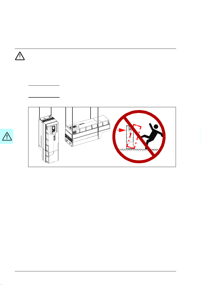
•Frames R5…R9: Do not tilt the drive. The drive is heavy and its center of
gravity is high. An overturning drive can cause physical injury.
5…R9: Lift the drive with a lifting device. Use the lifting eyes of the
• Beware of hot surfaces. Some parts, such as heatsinks of power semiconductors,
remain hot for a while after disconnection of the electrical supply.
• Keep the drive in its package or protect it otherwise from dust and burr from
drilling and grinding until you install it.
• Protect also the installed drive against dust and burr. Electrically conductive
debris inside the drive may cause damage or malfunction.
• Vacuum clean the area below the drive before the start-up to prevent the drive
cooling fan from drawing the dust inside the drive.
• Do not cover the air inlet and outlet when the drive runs.
• Make sure that there is sufficient cooling. See sections Checking the installation
site on page 54 and Losses, cooling data and noise on page 283 for more
information.
• Before you connect voltage to the drive, make sure that the drive covers are on.
Keep the covers on during the operation.
• Before you adjust the drive operation limits, make sure that the motor and all
driven equipment can operate throughout the set operation limits.

Safety instructions 17
• Before you activate the automatic fault reset or automatic restart functions of the
drive control program, make sure that no dangerous situations can occur. These
functions reset the drive automatically and continue operation after a fault or
supply break. If these functions are activated, the installation must be clearly
marked as defined in IEC/EN 61800-5-1, subclause 6.5.3, for example, “THIS
MACHINE STARTS AUTOMATICALLY”.
• If you have connected safety circuits to the drive (for example, emergency stop
and Safe torque off), validate them at the start up. For the validation of the Safe
torque off, see ACS580 standard control program firmware manual
(3AXD50000016097 [English]). For the validation of other safety circuits, see the
instructions provided with them.
Note:
• If you select an external source for start command and it is on, and the start
command is level-triggered, the drive will start immediately after fault reset. See
parameters 20.02 Ext1 start trigger type and 20.07 Ext2 start trigger type in
ACS580 standard control program firmware manual (3AXD50000016097
[English]).
• When the control location is not set to Local (text Local is not shown on the top
row of the panel and parameter 19.17 Local control disable has value Disabled),
the stop key on the control panel will not stop the drive.
• Frames R1…R5
: Do not attempt to repair a malfunctioning drive; contact your
local representative for replacement or repair by authorized persons.
Frames R6…R9: Can be repaired by authorized persons.

18 Safety instructions
Electrical safety in installation, start-up and maintenance
Precautions before electrical work
These warnings are for all personnel who do work on the drive, motor cable or motor.
WAR NING! Obey these instructions. If you ignore them, injury or death, or
damage to the equipment can occur. If you are not a qualified electrical
professional, do not do electrical installation or maintenance work. Go through these
steps before you begin any installation or maintenance work.
1. Clearly identify the work location.
2. Disconnect all possible voltage sources. Lock and tag.
• Open the main disconnector at the power supply of the drive.
• Make sure that reconnection is not possible.
• Disconnect any external power sources from the control circuits.
• After you disconnect the drive, always wait for 5 minutes to let the
intermediate circuit capacitors discharge before you continue.
3. Protect any other energized parts in the work location against contact.
4. Take special precautions when close to bare conductors.
5. Measure that the installation is de-energized.
• Use a multimeter with an impedance of at least 1 Mohm.
• Make sure that the voltage between the drive input power terminals (L1, L2,
L3) and the grounding terminal (PE) is close to 0 V.
• Make sure that the drive DC voltage is close to 0 V.
Frames R1…R3
grounding terminal (PE) with one multimeter. As there is no UDC- terminal,
measure the voltage between the drive T1/U terminal and grounding terminal
(PE) with another multimeter. Make sure that the voltage difference between
the multimeters is close to 0 V.
Frames R4…R9
and UDC-) and the grounding terminal (PE) and make sure that it is close to
0V.
: Measure the voltage between the drive UDC+ terminal and
: Measure the voltage between the drive DC terminals (UDC+
6. Install temporary grounding as required by the local regulations.
7. Ask for a permit to work from the person in control of the electrical installation
work
Safety instructions 19
Additional instructions and notes
WARNING! Obey these instructions. If you ignore them, injury or death, or
damage to the equipment can occur.
• A drive with the internal EMC filter connected can be installed to a symmetrically
grounded TN-S system. If you install the drive to another system, check if you
must disconnect the EMC filter. See sections
•IEC:
•North America:
drive.
Note: When the internal EMC filter is disconnected, the EMC compatibility of the
drive is considerably reduced. See section EMC compatibility and motor cable
length on page 297.
• A drive with the ground-to-phase varistor connected can be installed to a
symmetrically grounded TN-S system. If you install the drive to another system,
check if you must disconnect the varistor. See sections
•IEC:
•North America:
varistor circuit can be damaged.
• Use all ELV (extra low voltage) circuits connected to the drive only within a zone
of equipotential bonding, that is, within a zone where all simultaneously
accessible conductive parts are electrically connected to prevent hazardous
voltages appearing between them. You can accomplish this by a proper factory
grounding, that is, make sure that all simultaneously accessible conductive parts
are grounded to the protective earth (PE) bus of the building.
• Do not do insulation or voltage withstand tests on the drive or drive modules.
When to disconnect EMC filter or ground-to-phase varistor: TN-S, IT,
corner-grounded delta and midpoint-grounded delta systems on page 121,
and Guidelines for installing the drive to a TT system on page 122.
When to connect EMC filter or disconnect ground-to-phase
varistor: TN-S, IT, corner-grounded delta and midpoint-grounded delta
systems on page 175, and Guidelines for installing the drive to a TT system on
page 176.
WARNING! Do not install a drive with the EMC filter connected to a system
that the filter is not suitable for. This can cause danger, or damage the
When to disconnect EMC filter or ground-to-phase varistor: TN-S, IT,
corner-grounded delta and midpoint-grounded delta systems on page 121,
and Guidelines for installing the drive to a TT system on page 122.
When to connect EMC filter or disconnect ground-to-phase
varistor: TN-S, IT, corner-grounded delta and midpoint-grounded delta
systems on page 175, and Guidelines for installing the drive to a TT system on
page 176.
WARNING! Do not install a drive with the ground-to-phase varistor
connected to a system that the varistor is not suitable for. If you do, the
20 Safety instructions
Note:
• The motor cable terminals of the drive are at a dangerous voltage when the input
power is on, regardless of whether the motor is running or not.
• The DC and brake resistor terminals (UDC+, UDC-, R+ and R-) are at a
dangerous voltage.
• External wiring can supply dangerous voltages to the terminals of relay outputs
(RO1, RO2 and RO3).
• The Safe torque off function does not remove the voltage from the main and
auxiliary circuits. The function is not effective against deliberate sabotage or
misuse.
WARNING! Use a grounding wrist band when you handle the printed circuit
boards. Do not touch the boards unnecessarily. The boards contain
components sensitive to electrostatic discharge.
Grounding
These instructions are for all personnel who are responsible for the electrical
installation, including the grounding of the drive.
WAR NING! Obey these instructions. If you ignore them, injury or death, or
equipment malfunction can occur, and electromagnetic interference can
increase.
• If you are not a qualified electrical professional, do not do grounding work.
• Always ground the drive, the motor and adjoining equipment to the protective
earth (PE) bus of the power supply. This is necessary for the personnel safety.
Proper grounding also reduces electromagnetic emission and interference.
• In a multiple-drive installation, connect each drive separately to the protective
earth (PE) bus of the power supply.
• Make sure that the conductivity of the protective earth (PE) conductors is
sufficient. See section Selecting the power cables on page 91. Obey the local
regulations.
• Connect the power cable shields to the protective earth (PE) terminals of the
drive.
• Make a 360° grounding of the power and control cable shields at the cable entries
to suppress electromagnetic disturbances.

Safety instructions 21
Note:
• You can use power cable shields as grounding conductors only when their
conductivity is sufficient.
• Standards IEC/EN 61800-5-1 (section 4.3.5.5.2.) and UL 68100-5-1 require that
as the normal touch current of the drive is higher than 3.5 mA AC or 10 mA DC,
you must use a fixed protective earth (PE) connection. In addition,
• install a second protective earth conductor of the same cross-sectional area
as the original protective earthing conductor,
or
• install a protective earth conductor with a cross-section of at least 10 mm
or 16 mm
2
Al (when aluminum cables are allowed),
2
or
• install a device which automatically disconnects the supply if the protective
earth conductor breaks.
Cu

22 Safety instructions
Additional instructions for permanent magnet motor drives
Safety in installation, start-up and maintenance
These are additional warnings concerning permanent magnet motor drives. The other
safety instructions in this chapter are also valid.
WAR NING! Obey these instructions. If you ignore them, injury or death and
damage to the equipment can occur.
• Do not work on a drive when a rotating permanent magnet motor is connected to
it. A rotating permanent magnet motor energizes the drive including its input
power terminals.
Before installation, start-up and maintenance work on the drive:
• Stop the motor.
• Disconnect the motor from the drive with a safety switch or by other means.
• If you cannot disconnect the motor, make sure that the motor cannot rotate during
work. Make sure that no other system, like hydraulic crawling drives, can rotate
the motor directly or through any mechanical connection like felt, nip, rope, etc.
• Measure that the installation is de-energized.
• Use a multimeter with an impedance of at least 1 Mohm.
• Make sure that the voltage between the drive output terminals (T1/U, T2/V,
T3/W) and the grounding (PE) busbar is close to 0 V.
• Make sure that the voltage between the drive input power terminals (L1, L2,
L3) and the grounding (PE) busbar is close to 0 V.
• Make sure that the voltage between the drive DC terminals (UDC+, UDC-) and
the grounding (PE) terminal is close to 0 V.
• Install temporary grounding to the drive output terminals (T1/U, T2/V, T3/W).
Connect the output terminals together as well as to the PE.
Start-up and operation:
• Make sure that the motor cannot be run into overspeed, e.g. driven by the load.
Motor overspeed causes overvoltage that can damage or destroy the capacitors
in the intermediate circuit of the drive.
Safety instructions 23
General safety in operation
These instructions are for all personnel that operate the drive.
WARNING! Obey these instructions. If you ignore them, injury or death, or
damage to the equipment can occur.
• Do not power up the drive more than five times in ten minutes. Too frequent
power-ups can damage the charging circuit of the DC capacitors. If you need to
start or stop the drive, use the control panel start and stop keys or commands
through the I/O terminals of the drive.
• Give a stop command to the drive before you reset a fault. If you have an external
source for the start command and the start is on, the drive will start immediately
after the fault reset, unless you configure the drive for pulse start. See the
firmware manual.
• Before you activate automatic fault reset functions of the drive control program,
make sure that no dangerous situations can occur. These functions reset the
drive automatically and continue operation after a fault.
Note: When the control location is not set to Local, the stop key on the control panel
will not stop the drive.

24 Safety instructions

Introduction to the manual 25
2
Introduction to the manual
Contents of this chapter
The chapter describes applicability, target audience and purpose of this manual. It
describes the contents of this manual and refers to a list of related manuals for more
information. The chapter also contains a flowchart of steps for checking the delivery,
installing and commissioning the drive. The flowchart refers to chapters/sections in
this manual.
Applicability
The manual applies to the ACS580-01 drives, including the new (2017) R1…R3
frames (see all applicable types in section Electrical ratings on page 248).
Note: The manual does not apply to R0…R3 frames with type codes ACS580-01:
02A6-4, 03A3-4, 04A0-4, 05A6-4, 07A2-4, 09A-4, 12A6-4, 017A-4, 025A-4, 032A-4,
038A-4, 045A-4. For these types, see ACS580-01 (0.75 to 250 kW, 1.0 to 350 hp)
hardware manual (3AXD50000018826 [English]).
Target audience
The reader is expected to know the fundamentals of electricity, wiring, electrical
components and electrical schematic symbols.
The manual is written for readers worldwide. Both SI and imperial units are shown.
Special instructions for installations in North America are given.
Purpose of the manual
This manual provides information needed for planning the installation, installing, and
servicing the drive.

26 Introduction to the manual
Contents of this manual
The manual consists of the following chapters:
• Safety instructions (page 15) gives safety instructions you must obey when
installing, commissioning, operating and servicing the drive.
• Introduction to the manual (this chapter, page 25) describes applicability, target
audience, purpose and contents of this manual. It also contains a quick
installation and commissioning flowchart. At the end, it lists terms and
abbreviations.
• Operation principle and hardware description (page 35) describes the operation
principle, layout, power connections and control interfaces, type designation label
and type designation information in short.
• Mechanical installation (page 53) describes how to check the installation site,
unpack, check the delivery and install the drive mechanically.
• Guidelines for planning the electrical installation (page 83) describes how to plan
the electrical installation of the drive, for example, how to check the compatibility
of the motor and the drive and select cables, protections and cable routing.
• Electrical installation – IEC (page 117) describes how to check the insulation of
the assembly and the compatibility with other than symmetrically grounded TN-S
systems. It then shows how to connect the power and control cables, install
optional modules and connect a PC.
• Electrical installation – North America (page 171) describes how to check the
insulation of the assembly and the compatibility with other than symmetrically
grounded TN-S systems. It then shows how to connect the power and control
cables, install optional modules and connect a PC.
• Installation checklist (page 227) contains a checklist for checking the mechanical
and electrical installation of the drive before start-up.
• Maintenance and hardware diagnostics (page 229) contains preventive
maintenance instructions and LED indicator descriptions.
• Technical data (page 247) contains technical specifications of the drive, eg,
ratings, sizes and technical requirements as well as provisions for fulfilling the
requirements for CE, UL and other marks.
• Dimension drawings (page 317) shows dimension drawings of the drive.
• Resistor braking (page 345) tells how to select the brake resistor.
• Safe torque off function (page 353) describes STO features, installation and
technical data.
• Optional I/O extension modules (page 373) describes CMOD-01, CMOD-02, and
CHDI-01 and CBAI-01 extension modules, their installation, start-up, diagnostics
and technical data.
• Common mode, du/dt and sine filters (page 405) describes selection of external
filters for the drive.

Introduction to the manual 27
• Further information (inside of the back cover, page 411) tells how to make product
and service inquiries, get information on product training, provide feedback on
manuals and find documents on the Internet.
Categorization by frame (size)
The ACS580-01 is manufactured in frames (frame sizes) R1…R9. Some instructions
and other information that only concern certain frames are marked with the symbol of
the frame (R1…R9). The frame is marked on the type designation label attached to
the drive, see section Type designation label on page 47.
Related documents
You can find manuals and other product documents in PDF format on the Internet.
See section Document library on the Internet on the inside of the back cover. For
manuals not available in the Document library, contact your local ABB representative.
Drive manuals and guides Code (English)
ACS580 standard control program firmware manual
ACS580-01 (0.75 to 250 kW, 1.0 to 350 hp) hardware
manual
ACS580-01 frames R1 to R5 quick installation and start-
up guide
ACS580-01 frames R6 to R9 quick installation and start-
up guide
ACx-AP-X assistant control panels user’s manual
3AXD50000016097
3AXD50000044794
3AXD50000044838
3AXD50000009286
3AUA0000085685
Option manuals and guides
ACS580, ACH580 and ACQ580 drive module frames
R3 and R5 to R9 for cabinet installation (options +P940
and +P944) supplement
ACS580-01, ACH580-01 and ACQ580-01 installation
guide for UK gland plate (option +H358)
CPTC-02 ATEX-certified thermistor protection module,
Ex II (2) GD (+L537+Q971) user's manual
CDPI-01 communication adapter module user's manual
DPMP-01 mounting platform for control panels
DPMP-02/03 mounting platform
DPMP-06/07 mounting platform
FCAN-01 CANopen adapter module user's manual
FCNA-01 ControlNet adapter module user's manual
FDNA-01 DeviceNet™ adapter module user's manual
FECA-01 EtherCAT adapter module user's manual
FEIP-21 Ethernet/IP adapter module user’s manual
FENA-01/-11/-21 Ethernet adapter module user's
manual
FEPL-02 Ethernet POWERLINK adapter module user's
manual
FMBT-21 Modbus/TCP adapter module user’s manual
for control panels
for control panels
3AXD50000210305
3AXD50000034735
3AXD50000030058
3AXD50000009929
3AUA0000100140
3AUA0000136205
3AXD50000289561
3AFE68615500
3AUA0000141650
3AFE68573360
3AUA0000068940
3AXD50000158621
3AUA0000093568
3AUA0000123527
3AXD50000158607

28 Introduction to the manual
ACS580-01 manuals
FPBA-01 PROFIBUS DP adapter module user's manual
FPNO-21 PROFINET adapter module user’s manual
FSCA-01 RS-485 adapter module user's manual 3AUA0000109533
ACS580-01…, ACH580-01… and ACQ580-01…+C135
drives with flange mounting kit supplement
ACS580-01…, ACH580-01… and ACQ580-01…+C135
frames R1 to R3 flange mounting kit quick installation
guide
ACS580-01…, ACH580-01… and ACQ580-01…+C135
frames R4 to R5 flange mounting kit quick installation
guide
ACS880-01…, ACS580-01…, ACH580-01… and
ACQ580-01…+C135 frames R4 to R5 flange mounting
kit quick installation guide
Main switch and EMC C1 filter options (+F278, +F316,
+E223) installation supplement for ACS580-01,
ACH580-01 and ACH580-01 frames R1 to R5
UL Type 12 hood quick installation guide for ACS58001, ACH580-01 and ACQ580-01 frames R1 to R9
Tool and maintenance manuals and guides
Drive composer PC tool user's manual 3AUA0000094606
Converter module capacitor reforming instructions
NETA-21 remote monitoring tool user's manual
NETA-21 remote monitoring tool installation and start-up
guide
3AFE68573271
3AXD50000158614
3AXD50000019100
3AXD50000119172
3AXD50000287093
3AXD50000019099
3AXD50000155132
3AXD50000196067
3BFE64059629
3AUA0000096939
3AUA0000096881
Introduction to the manual 29
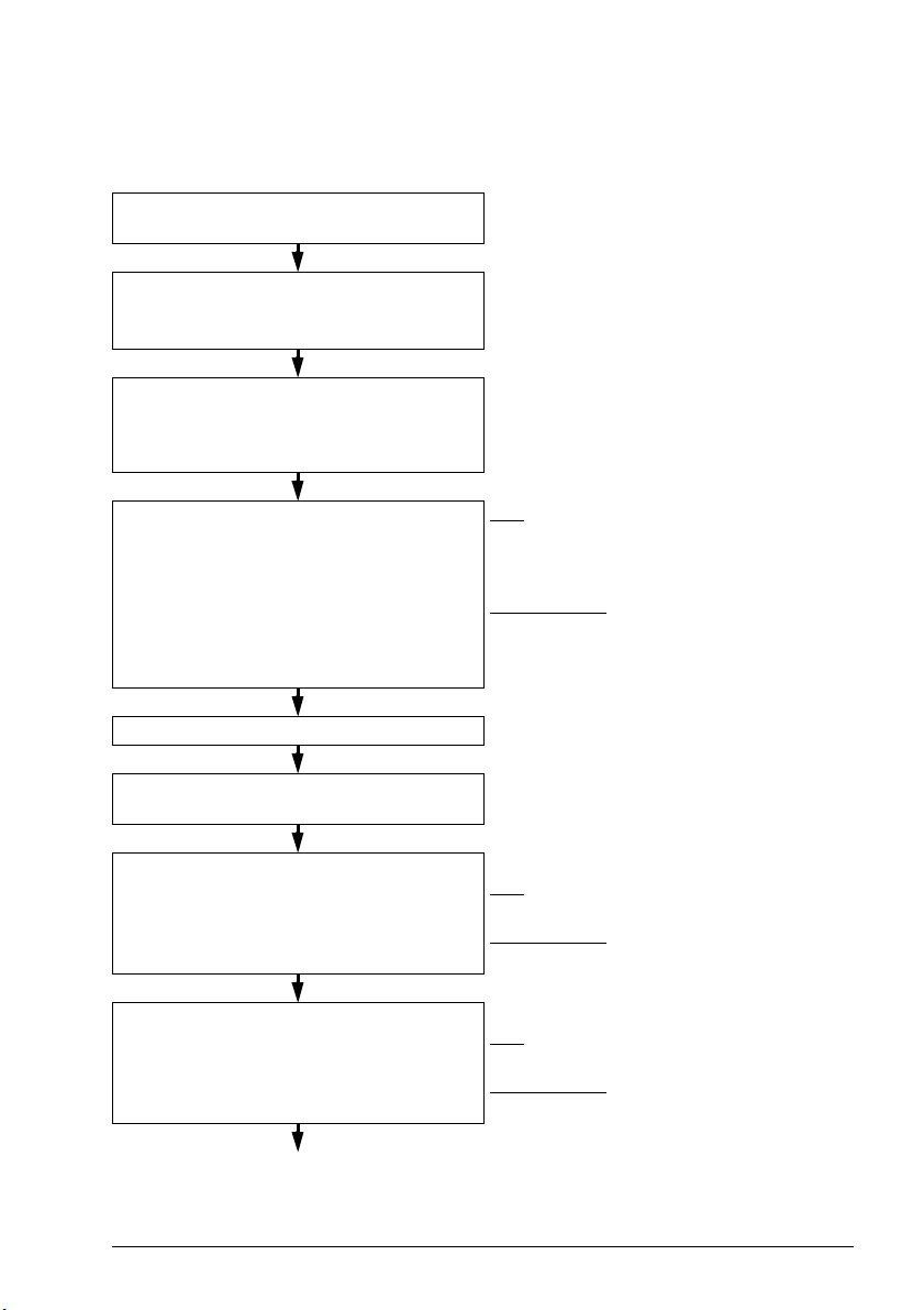
Quick installation and commissioning flowchart
Tas k Se e
Identify the frame of your drive: R1…R9. Operation principle and hardware description:
Type designation key on page 49
Plan the installation: select the cables, etc.
Check the ambient conditions, ratings and
required cooling air flow.
Unpack and check the drive.
Check that all necessary optional modules
and equipment are present and correct.
If the drive will be connected to another
system than symmetrically grounded TN-S
system: Check if you must disconnect the
EMC filter or ground-to-phase varistor.
Install the drive on a wall. Mechanical installation on page 53
Route the cables. Guidelines for planning the electrical
Check the insulation of the input cable and the
motor and the motor cable.
Guidelines for planning the electrical
installation on page 83
Technical data on page 247
Mechanical installation: Unpacking and
examining delivery, frames R1 and R2 on
page 59; R3 on page 62; R4 on page 64; R5
on page 66; R6…R9 on page 68
IEC:
Checking the compatibility with IT
(ungrounded), corner-grounded delta,
midpoint-grounded delta and TT systems on
page 120
North America:
with IT (ungrounded), corner-grounded delta,
midpoint-grounded delta and TT systems on
page 174
installation: Routing the cables on page 104
Electrical installation:
IEC:
Checking the insulation of the assembly
on page 118
North America:
assembly on page 172
Checking the compatibility
Checking the insulation of the
Connect the power cables. Electrical installation:
IEC:
Connecting the power cables on page
127
North America:
on page 182
Connecting the power cables
30 Introduction to the manual
Tas k Se e
Connect the control cables. Electrical installation:
IEC:
Connecting the control cables on page
146
North America:
on page 182
Check the installation. Installation checklist on page 227
Commission the drive. ACS580 standard control program firmware
manual (3AXD50000016097 [English])
Connecting the control cables

Introduction to the manual 31
Terms and abbreviations
Term/abbreviation Explanation
ACS-BP-S Basic control panel, basic operator keypad for communication with the
Assistant control
panel
Brake chopper Conducts the surplus energy from the intermediate circuit of the drive to
Brake resistor Dissipates the drive surplus braking energy conducted by the brake
Control board Circuit board in which the control program runs.
Capacitor bank See DC link capacitors.
CBAI-01 CBAI-01 bipolar analog IO extension module
CCA-01 Configuration adapter
CDPI-01 Communication adapter module
CHDI-01 Optional 115/230 V digital input extension module
CMOD-01 Optional multifunction extension module (external 24 V AC/DC and
CMOD-02 Optional multifunction extension module (external 24 V AC/DC and
CPTC-02 Optional multifunction extension module (external 24 V and ATEX
DC link DC circuit between rectifier and inverter
DC link capacitors Energy storage which stabilizes the intermediate circuit DC voltage
DPMP-01 Mounting platform for ACS-AP control panel (flange mounting). CDP-01
DPMP-02 Mounting platform for ACS-AP control panel (surface mounting).
DPMP-EXT Door mounting kit for the panel. For one drive; contains both DPMP-02
Drive Frequency converter for controlling AC motors
EMC Electromagnetic compatibility
EFB Embedded fieldbus
FBA Fieldbus adapter
FCAN-01 Optional CANopen adapter module
drive. The ACS580 supports ACS-BP-S basic control panel.
Assistant control panel (ACS-AP-x) is an advanced operator keypad for
communication with the drive. The ACS580 supports types ACS-AP-I
and ACS-AP-S, as well as ACS-AP-W, which has a Bluetooth interface.
the brake resistor when necessary. The chopper operates when the DC
link voltage exceeds a certain maximum limit. The voltage rise is
typically caused by deceleration (braking) of a high inertia motor.
chopper to heat. Essential part of the brake circuit. See Brake chopper.
digital I/O extension)
isolated PTC interface)
certified PTC interface)
communication adapter module is needed to connect the DMP0-01 to
the drive. For up to 32 drives on a panel bus with a single panel on
cabinet door, one DMP-02 with one CDPI-01 per each drive are used.
CDP-01 communication adapter module is needed to connect the
DMP0-02 to the drive. For up to 32 drives on a panel bus with a single
panel on cabinet door, one DMP-02 with one CDPI-01 per each drive
are used.
and CDPI-01, which connects the DPMP-02 to the drive.

32 Introduction to the manual
Term/abbreviation Explanation
FCNA-01 ControlNet adapter module
FDNA-01 Optional DeviceNet adapter module
FECA-01 Optional EtherCAT adapter module
FEIP-21 Optional two-port Ethernet/IP adapter module
FENA-21 Optional two-port Ethernet adapter module for EtherNet/IP, Modbus
TCP and PROFINET IO protocols
FEPL-02 Optional Ethernet POWERLINK adapter module
FMBT-21 Optional two-port Modbus/TCP adapter module
FPBA-01 Optional PROFIBUS DP adapter module
FPNO-21 Optional PROFINET IO adapter module
Frame (size) Refers to drive physical size, for example R1 and R2. The type
designation label attached to the drive shows the frame of the drive, see
section Type designation key on page 49.
FSCA-01 Optional EIA-485 adapter module
I/O Input/Output
IGBT Insulated gate bipolar transistor
Intermediate circuit See DC link.
Inverter Converts direct current and voltage to alternating current and voltage.
Macro Pre-defined default values of parameters in drive control program. Each
NEC 70 National Fire Protection Association (National Electric Code 70)
NETA-21 Remote monitoring tool
Network control With fieldbus protocols based on the Common Industrial Protocol
Parameter User-adjustable operation instruction to the drive, or signal measured or
PLC Programmable logic controller
PROFIBUS,
PROFIBUS DP,
PROFINET IO
PTC Positive temperature coefficient (PTC) refers to materials that
R1, R2, … Frame (size)
macro is intended for a specific application. See ACS580 firmware
manual (3AXD50000016097[English]).
TM
), such as DeviceNet and Ethernet/IP, denotes the control of the
(CIP
drive using the Net Ctrl and Net Ref objects of the ODVA AC/DC Drive
Profile. For more information, see www.odva.org
, and the following
manuals:
• FDNA-01 DeviceNet adapter module user’s manual (3AFE68573360
[English]), and
• FENA-01/-11/-21 Ethernet adapter module user’s manual
(3AUA0000093568 [English])
calculated by the drive
Registered trademarks of PI - PROFIBUS & PROFINET International
experience an increase in electrical resistance when their temperature
is raised.

Introduction to the manual 33
Term/abbreviation Explanation
Rectifier Converts alternating current and voltage to direct current and voltage.
SIL Safety integrity level. See chapter Safe torque off function on page 353.
STO Safe torque off. See chapter Safe torque off function on page 353.

34 Introduction to the manual

Operation principle and hardware description 35
3
Operation principle and hardware description
Contents of this chapter
This chapter briefly describes the operation principle, layout, type designation label
and type designation information. It also shows a general diagram of power
connections and control interfaces.

36 Operation principle and hardware description
L1
L2
L3
T1/U
T2/V
T3/W
R- UDC+
R+
1 2 3
4
UDC-
5
ACS580-01
Operation principle
The ACS580-01 is a drive for controlling asynchronous AC induction motors,
permanent magnet motors and synchronous reluctance motors (SynRM).
The figure below shows the simplified main circuit diagram of the drive.
1 Rectifier. Converts alternating current and voltage to direct current and voltage.
2 DC link. DC circuit between rectifier and inverter.
3 Inverter. Converts direct current and voltage to alternating current and voltage.
4 Built-in brake chopper (R-, R+) in frames R1…R3. Conducts the surplus energy from
the intermediate DC circuit of the drive to the brake resistor when necessary. The
chopper operates when the DC link voltage exceeds a certain maximum limit. The
voltage rise is typically caused by deceleration (braking) of a high inertia motor. The
user obtains and installs the brake resistor when needed.
5 DC connection (UDC+, UDC-), for an external brake chopper in frames R4…R9.

Layout
1 Mounting points (4 pieces)
2 Cover: upper part (2a), lower part (2b)
3 Cover screw
4 Cable/conduit box
5 Control panel
6 Control panel connection
7 Cold configuration connection for CCA-01
7 Power OK and Fault LEDs. See section
LEDs on page 244.
8 I/O connections. See section External
control connection terminals, frames
R1…R5 on page 44.
9 Varistor grounding screw (VAR).
See Frames R1…R3 on page 124 (IEC)
or Frames R1…R3, disconnecting EMC
or varistor screws (North America) on
page 178.
6
7
8
11
8
18
1
5
1
2a
PE
10
20
R1 IP21 / UL Type 1
14
15
20
21
1
16
17
3
12
2b
4
19
9
13
10 EMC filter grounding screw (EMC (DC)).
See Frames R1…R3 on page 124 (IE C or
Frames R1…R3, disconnecting EMC or
varistor screws (North America) on page
178.
11 Place for storing the removed VAR screw
12 Place for storing the removed EMC screw
13 Input power connection (L1, L2, L3),
motor connection (T1/U, T2/V, T3/W) and
brake connection (R-, R+)
14 PE connection (power line)
15 Grounding connection (motor)
16 Additional grounding connection
17 Stripping length (8 mm) checker
18 Cable entry
19 Main cooling fan
20 Cable tie mounts for /I/O cables
21 Auxiliary cooling fan connector
Frames R1…R2
The layout of a frame R1 drive is presented below. The main structure of frame R2 is
similar to R1. IP55 / UL Type 12 frames are also slightly different from IP21 /
UL Type 1 frames, for example, IP21 / UL Type 1 front cover has two parts while
IP55 / UL Type 12 front cover only has one part.
Operation principle and hardware description 37

38 Operation principle and hardware description
R1 IP55 / UL Type 12
1 Mounting points (4 pieces), top points are
under the hood, which is installed last.
2 Front cover
3 Cover screws (2 pieces)
4 Control panel behind the transparent
window
5 Hood, UL Type 12 only. Hood types vary
by the frame size, see page 278.
1
2
3
4
1
3
5
This is an example of IP55 / UL Type 12 frames. They have one-piece front cover,
which has a transparent window to leave the control panel visible. UL Type 12 frames
have a hood, whose construction depends on the frame size.

Frame R3
BRAKE RES
INPUT
PE
MOTOR
R-
R+
UDC+
L1
L2
L3
T1/U
T2/V
T3/W
1 Mounting points (4 pieces)
2Cover
3 Cover screw
4 Control panel
5 Control panel connection
6 Cold configuration connection for CCA-01
7 Power OK and Fault LEDs. See section
LEDs on page 244.
8 I/O connections. See section External
control connection terminals, frames
R1…R5 on page 44.
9 Varistor grounding screw (VAR).
See Frames R1…R3 on page 124 (IEC)
or Frames R1…R3, disconnecting EMC
or varistor screws (North America) on
page 178.
10 EMC filter grounding screw (EMC (DC)).
See Frames R1…R3 on page 124 (IEC)
or Frames R1…R3, disconnecting EMC
or varistor screws (North America) on
page 178.
11 Input power connection (L1, L2, L3),
motor connection (T1/U, T2/V, T3/W) and
brake connection (R-, R+)
12 PE connection (power line)
13 Grounding connection (motor)
14 Additional grounding connection
15 Cable entry
16 Main cooling fan
17 Cable tie mounts for I/O cables
18 Auxiliary cooling fan. For
IP55/UL Type 12 drives only.
19 Auxiliary cooling fan connector
20 Place for storing the removed EMC screw
21 Place for storing the removed VAR screw
5
6
7
8
16
15
1
4
1
2
11
3
PE
R3 IP21 / UL Type 1
1
12
13
17
19
17
8
20 21
9
10
18
14
Operation principle and hardware description 39

40 Operation principle and hardware description
1 Mounting points (4 pieces)
2Cover
3 Cover screw
4 Control panel
5 Control panel connection
6 Cold configuration connection for CCA-01
7 Power OK and Fault LEDs. See section
LEDs on page 244.
8 I/O connections. See section External
control connection terminals, frames
R1…R5 on page 44.
9 Varistor grounding screw (VAR).
See Frames R4…R9 on page 125 (IEC)
or Frames R4…R9, disconnecting EMC
or varistor screws (North America) on
page 180.
10 Two EMC filter grounding screws, 10a:
EMC (DC) and 10b: EMC (AC).
See Frames R4…R9 on page 125 (IEC)
or Frames R4…R9, disconnecting EMC
or varistor screws (North America) on
page 180.
11 Input power connection (L1, L2, L3),
motor connection (T1/U, T2/V, T3/W) and
DC connection (UDC+, UDC-)
12 PE connection (power line)
13 Grounding connection (motor)
14 Cable entry
15 Main cooling fan
16 Cable tie mounts for I/O cables
17 Auxiliary cooling fan. For
IP55/UL Type 12 drives only.
18 Auxiliary cooling fan connector
19 Additional grounding connection
5
6
17
11
8
14
1
4
1
2
3
PE
R4 IP21 / UL Type 1
12
13
16
9
1
7
8
15
16
10b
10a
18
19
Frame R4

Frame R5
1 Mounting points (6 pieces: 2 at the top, 2
at the bottom of the main part of the
frame, 2 at the top of the cable box)
2Cover
3 Cable/conduit box
4 Cover screws (2 pieces)
5 Control panel
6 Control panel connection
7 Cold configuration connection for CCA-01
8 Power OK and Fault LEDs. See section
LEDs on page 244.
9 I/O connections. See section External
control connection terminals, frames
R1…R5 on page 44.
10 Varistor grounding screw (VAR).
See Frames R4…R9 on page 125 (IEC)
or Frames R4…R9, disconnecting EMC
or varistor screws (North America) on
page 180.
11 Two EMC filter grounding screws, 11a:
EMC (DC) and 11b: EMC (AC).
See Frames R4…R9 on page 125 (IEC)
or Frames R4…R9, disconnecting EMC
or varistor screws (North America) on
page 180.
12 Input power connection (L1, L2, L3),
motor connection (T1/U, T2/V, T3/W) and
DC connection (UDC+, UDC-) under the
shroud
13 PE connection (power line)
14 Grounding connection (motor)
15 Cable box plate
16 Cable entry
17 Main cooling fan
18 Cable tie mounts for I/O cables
19 Auxiliary cooling fan connector
2
3
R5 IP21 / UL Type 1
1
5
1
1
10
4
9
9
12
PE
13
14
16
18
18
15
17
6
7
8
11b
11a
19
Operation principle and hardware description 41

42 Operation principle and hardware description
1 Mounting points (6 pieces: 2 at the top, 2
at the bottom of the main part of the
frame, 2 at the top of the cable box)
2 Cover
3 Cable/conduit box
4Heatsink
5 Lifting holes (6 pieces)
6 Control panel
7 Control panel connection
8 Cold configuration connection for CCA-01
9 Power OK and Fault LEDs. See section
LEDs on page 244.
10 I/O connections. See section External
control connection terminals, frames
R6…R9 on page 45.
11 Cable tie mounts for I/O cables
12 Clamps for I/O cable mechanical support
13 Varistor grounding screw (VAR), under
the control panel platform.
See Frames R4…R9 on page 125 (IEC)
or Frames R4…R9, disconnecting EMC
or varistor screws (North America) on
page 180.
14 Two EMC filter grounding screws, 14a:
EMC (DC) under the control panel
platform and 14b: EMC (AC) at the left,
above the shroud.
See Frames R4…R9 on page 125 (IEC)
or Frames R4…R9, disconnecting EMC
or varistor screws (North America) on
page 180.
15 Shroud. Under the shroud: Input power
connection (L1, L2, L3), motor connection
(T1/U, T2/V, T3/W) and DC connection
(UDC+, UDC-).
16 PE connection (power line)
17 Grounding connection (motor), under the
shroud (15).
18 Cable entry
19 Main cooling fan
20 Auxiliary cooling fan
R6 IP21 / UL Type 1
1
5
2
4
3
5
6
7
8
9
10
10
13
20
18
15
12
12
16
11
1
19
5
PE
17
14a
14b
Frames R6…R9
The layout of a frame R6 drive is presented below. The constructions of frames
R6…R9 differ to some extent.

Operation principle and hardware description 43
Slot 2
L1
L2
L3
PE
T1/U
T2/V
T3/W
M
3 ~
L1
L2
L3
PE
R-
UDC+
R+
UDC-
Slot 1
1
2
..........
..........
..........
..........
..........
..........
Panel port
3
1)
1)
4
Overview of power and control connections
The logical diagram below shows the power connections and control interfaces of the
drive.
1 Option slot 1 for optional fieldbus adapter modules
2 Option slot 2 for optional I/O extension modules
3 Panel port.
4du/dt or common mode filter (optional), see page 405.
1)
Not in all frame sizes.

44 Operation principle and hardware description
Description
X1 Analog inputs and outputs
X2 Aux. voltage output
X3 Programmable digital inputs
X4 Safe torque off connection
X5 Embedded fieldbus
X6 Relay output 3
X7 Relay output 2
X8 Relay output 1
X10 Auxiliary fan connection (IP55)
X13 Option slot 1 (fieldbus adapter
modules)
X14 Option slot 2 (I/O extension
modules)
S4, S5 Termination switch (S4), bias
resistor switch (S5), see section
Switches on page 150 (IEC) or
Switches on page 150 (North
America)
1 Panel port (control panel
connection)
2 Cold configuration connection. This
connector is used with the CCA-01
configuration adapter.
3 Power OK and Fault LEDs. See
section LEDs on page 244.
1
2
3
S4
X5
S5
X13
X14
X3
X2
X4
X1
X6
X7
X8
X10
R1…R5
External control connection terminals, frames R1…R5
The layout of the external control connection terminals of the R1 frame is shown
below. Layout of the external control connection terminals is identical in frames
R1…R5 but the location of the control board with the terminals is different in frames
R3…R5.

Operation principle and hardware description 45
2
Description
X1 Analog inputs and outputs
X2 Aux. voltage output
X3 Digital inputs
X4 Safe torque off connection
X5 Connection to embedded EIA-
485 fieldbus adapter module
X6 Relay output 3
X7 Relay output 2
X8 Relay output 1
X10 External +24 V AC/DC input
connection
X12 Panel connection
X13 Option slot 1 (fieldbus adapter
modules)
X14 Option slot 2 (I/O extension
modules)
X16 Auxiliary fan 1 connection
X17 Auxiliary fan 2 connection
S4, S5 Termination switch (S4), bias
resistor switch (S5), see section
Switches on page 150 (IEC) or
Switches on page 150 (North
America)
1 Panel port (control panel
connection)
2 Cold configuration connection.
This connector is used with the
CCA-01 configuration adapter.
3 Power OK and Fault LEDs. See
section LEDs on page 244.
R6…R9
X2
X4
X13
1
3
X8
X7
X6
X10
X5
S4, S5
X17X16
X14
X1:1…3
X1:4…6
X1:7…9
X3:1…3
X3:4…6
X12
External control connection terminals, frames R6…R9
The layout of the external control connection terminals of frames R6…R9 is shown
below.
WARNING! Do not connect the +24 V AC cable to the control board ground when the
control board is powered using an external 24 V AC supply.

46 Operation principle and hardware description
1a
1b
1a
1b
1c
Control panel
To remove the control panel, press the retaining clip at the top (1a) and pull it forward
from the top edge (1b).
To reinstall the control panel, put the bottom of the container in position (1a), press
the retaining clip at the top (1b) and push the control panel in at the top edge (1c).
For the use of the control panel, see ACS580 standard control program firmware
manual (3AXD50000016097 [English]) and ACX-AP-X assistant control panels user’s
manual (3AUA0000085685 [English]).

Operation principle and hardware description 47
1
3
7
8
9
4
5
2
6
Control panel door mounting kits
Door mounting kits for the control panel are available.
For more information, see DPMP-01 mounting platform for control panels
(3AUA0000100140 [English]), DPMP-02/03 mounting platform for control panels
(3AUA0000136205 [English]) or DPMP-06/07 mounting platform for control panels
(3AXD50000289561 [English]).
Type designation label
The type designation label includes IEC and UL (NEC) ratings, appropriate markings
and the type designation and serial number, which allow identification of each drive.
The type designation label is located on the left side of the drive, see section
Locations of the labels on the drive. An example label is shown below.
No. Description
1 Type designation, see section Type designation key on page 49.
2 Name and address of the manufacturer
3 Frame (size)
4 Type of the drive, for example, with Air cooling or Liquid cooling, and so on.
5 Degree of protection
6 IEC: Icc (Rated conditional short-circuit current) = 100 kA,
UL (NEC): SCCR (Short circuit current rating) = 100 kA
7 Nominal ratings in the supply voltage range, see section Electrical ratings on page 248,
section Electrical power network specification on page 294 and section Motor connection
data on page 295.
See page 294 for further information on input voltage range.
8 Valid markings
9 S/N: Serial number of format MYYWWXXXX, where
M:
YY:
WW:
XXXXX:
Manufacturing plant
16, 17, 18, … for 2016, 2017, 2018, …
01, 02, 03, … for week 1, week 2, week 3, …
Digits making the serial number unique

48 Operation principle and hardware description
1
2
3
Locations of the labels on the drive
1
2
3
Note: Pn is not shown in UL (NEC) drive labels.

Operation principle and hardware description 49
ACS580-01-12A7-4+L501+K457+...
1 2 3 4
1
2
3
4
Type designation key
The type designation contains information on the specifications and configuration of
the drive. You find the type designation on the type designation label attached to the
drive. The first digits from the left express the basic configuration, for example,
ACS580-01-12A7-4. The optional selections are given after that, separated by plus
signs, for example, +L501. The main selections are described below. Not all
selections are available for all types.
CODE DESCRIPTION
Basic codes
ACS580 Product series
01 When no options are selected: Wall mounted, IP21 (UL Type 1), assistant
Size
xxxx Refer to the rating table, page 248
Voltage rating
4 2 = 200…240 V
Option codes (plus codes)
Control panel and panel options
J400 ACS-AP-S Assistant control panel (as standard)
J404 ACS-BP-S Basic control panel
J424 CDUM-01 Blank control panel cover (no control panel)
J425 ACS-AP-I Assistant control panel
J429 ACS-AP-W Assistant control panel with a Bluetooth interface
I/O (one slot available for I/O options)
L500 CBAI-01 Bipolar analog IO extension
L501 CMOD-01 External 24 V AC/DC and digital I/O extension (2×RO and 1×DO)
L512 CHDI-01 115/230 V Digital input extension (6×DI and 2×RO)
L523 CMOD-02 External 24 V AC/DC and isolated PTC interface
L537 CPTC-02 ATEX certified PTC interface and external 24 V. Requires option
control panel with a USB port, choke, EMC C2 filter (internal EMC filter), safe
torque off, braking chopper in frames R1, R2, R3, coated boards, cable lead
through entry from the bottom, cable box or the conduit plate with cable
entries, quick installation and start-up guide (multilingual).
4 = 380…480 V
6 = 575…600 V
See page 294 for further information.
Q971. Europe only.

50 Operation principle and hardware description
CODE DESCRIPTION
Safety
Q971 ATEX certified safe disconnection function, EX II (2) GD. Available only with
option L357. Europe only.
Fieldbus adapters
K451 FDNA-01 DeviceNet™
K454 FPBA-01 PROFIBUS DP
K457 FCAN-01 CANopen
K458 FSCA-01 Modbus/RTU
K462 FCNA-01 ControlNet™
K469 FECA-01 EtherCAT
K470 FEPL-02 Ethernet POWERLINK
K475 FENA-21 Two-port Ethernet (EtherNet/IP™, Modbus/TCP, PROFINET)
K490 FEIP-21 Two-port EtherNet/IP
K491 FMBT-21 Two-port Modbus/TCP
K492 FPNO-21 Two-port PROFINET IO
Embedded fieldbus
CEIA-01 Embedded Modbus RTU adapter, EIA-485 (as standard)
Construction
B056 IP55 (UL type 12). Factory option, retro-fit not possible.
C135 Flange mounting kit. Flange mounting kit is ordered separately North
America, not with a plus code.
E223 EMC filter, category C1 for earthed network. For frame sizes R1
F278 Main switch. For frame sizes R1
F316 Main switch and EMC filter, category C1 for earthed network. For frame sizes
H358 Cable conduit plate, blank.
Requires option B056. IEC only.
…R5. Requires option B056. IEC only. Valid
for APAN region.
R1
…R5. Requires option B056. IEC only.
…R5.

Operation principle and hardware description 51
CODE DESCRIPTION
Full set of printed manuals in selected language.
Note: The delivered manual set may include manuals in English if the translation is not
available.
Note: These options are not available in North America. You can find manuals in PDF
format on the Internet. See section Document library on the Internet on the inside of the
back cover.
R700 English
R701 German
R702 Italian
R703 Dutch
R704 Danish
R705 Swedish
R706 Finnish
R707 French
R708 Spanish
R709 Portuguese (Brazil)
R711 Russian
R712 Chinese
R713 Polish
R714 Turkish
3AXD10000081909

52 Operation principle and hardware description

Mechanical installation 53
4
Mechanical installation
Contents of this chapter
This chapter tells how to check the installation site, unpack, check the delivery and
install the drive mechanically.
Safety
WARNING! Frames R5…R9: Lift the drive with a lifting device. Use the lifting
eyes of the drive. Do not tilt the drive. The drive is heavy and its center of
gravity is high. An overturning drive can cause physical injury.

54 Mechanical installation
a
b
c
b
b
Frame size R4 R9
Hood height (in) 2.83 9.06
Hood height (mm) 72 230
Checking the installation site
The drive must be installed on the wall or an enclosure. There are three alternative
ways to install it:
•V
ertical
Note: Do not install the drive upside down.
Frame
size
Above (a)
mm in mm in mm in mm in mm in mm in
IP21 (UL Type 1) IP55 (UL Type 12)
1)
Below (b)2)Beside
R1 150 5.91 86 3.39 150 5.91 137 5.39 116 4.57 150 5.91
R2 150 5.91 86 3.39 150 5.91 137 5.39 116 4.57 150 5.91
R3 200 7.87 53 2.09 150 5.91 200 7.87 53 2.09 150 5.91
R4 53 2.09 200 7.87 150 5.91 53 2.09 200 7.87 150 5.91
R5 100 3.94 200 7.87 150 5.91 100 3.94 200 7.87 150 5.91
R6 155 6.10 300 11.81 150 5.91 155 6.10 300 11.81 150 5.91
R7 155 6.10 300 11.81 150 5.91 155 6.10 300 11.81 150 5.91
R8 155 6.10 300 11.81 150 5.91 155 6.10 300 11.81 150 5.91
R9 200 7.87 300 11.81 150 5.91 200 7.87 300 11.81 150 5.91
1)
Free space above is measured from the frame, not from the hood used in UL Type 12 frames.
Note: The height of the hood for frames R4 and R9 exceeds the requirement of free space above for
these frames
Vertical installation - Free space
(c)3)Above (a)1)Below (b)2)Beside
3AXD00000586715.xls L
(c)
3)
2)
Free space below is always measured from the drive frame, not from the cable box

Mechanical installation 55
3)
Free space between the drive and other objects, e.g. wall.
Note: The recommended free space above and below the drive is for installations where the drive is
mounted on a wall indoors. For ABB cabinet-built drives, which are thermally tested and approved for a
specified temperature range, free space could vary from this recommendation.

56 Mechanical installation
Frame
size
Vertical installation side by side - Free space,
IP21 (UL Type 2) and IP55 (UL Type 12)
Above (a)
1)
Below (b)
2)
Between (c)
3)
mm in mm in mm in
R1 200 7.87 200 7.87 0 0
R2 200 7.87 200 7.87 0 0
R3 200 7.87 200 7.87 0 0
R4 200 7.87 200 7.87 0 0
R5 200 7.87 200 7.87 0 0
R6 2007.8730011.81 0 0
R7 2007.8730011.81 0 0
R8 2007.8730011.81 0 0
R9 2007.8730011.81 0 0
3AXD00000586715.xls L
1)
Free space above is measured from the frame, not from the hood used in UL Type 12 frames.
Note: The height of the hood for frames R4 and R9 exceeds the requirement of free space above for
these frames.
2)
Free space below is always measured from the drive frame, not from the cable box.
3)
Free space between the drives.
Note: The recommended free space above and below the drive is for installations where the drive is
mounted on a wall indoors. For ABB cabinet-built drives, which are thermally tested and approved for a
specified temperature range, free space could vary from this recommendation.
Note for IP21 (UL Type 1) frames R1…R2: The cover fastening clips can be removed to make the front
cover opening easier.
Note for IP55 (UL Type 12) frames R1…R2: Auxiliary fan maintenance cannot be performed without
removing every second drive from installation to get access to the fan.
Frame size R4 R9
Hood height (in) 2.83 9.06
Hood height (mm) 72 230
a
b
a
b
c= 0
•Vertical side by side

Mechanical installation 57
Frame
size
Horizontal installation - Free space
IP21 (IP20) IP55 (UL Type 12)
Above (a) Below (b)
1)
Above (a) Below (b)
1)
mm in mm in mm in mm in
R1 150 5.91 86 3.39 137 5.39 116 4.57
R2 150 5.91 86 3.39 137 5.39 116 4.57
R3 200 7.87 53 2.09 200 7.87 53 2.09
R4 30 1.18 200 7.87 30 1.18 200 7.87
R5 30 1.18 200 7.87 30 1.18 200 7.87
Frame
size
Side up (c) Side down (d) Side up (c) Side down (d)
mm in mm in mm in mm in
R1 30 1.18 200 7.87 30 1.18 200 7.87
R2 30 1.18 200 7.87 30 1.18 200 7.87
R3 30 1.18 200 7.87 30 1.18 200 7.87
R4 30 1.18 200 7.87 30 1.18 200 7.87
R5 30 1.18 200 7.87 30 1.18 200 7.87
3AXD00000586715.xls L
1)
Free space below is always measured from the drive frame, not from the cable box.
d
c
d
c
a
b
b
a
•Horizontal, IP20 and IP55, R1…R5 only
Note 1: You can install IP21 / UL Type 1 drives horizontally but the installation
meets IP20 requirements only.
Note 2: IP55/Type 12 drive mounted horizontally meet IP21/Type 1 ratings.
Note 3: In the horizontal mounting, the drive is not protected from dripping water.
Note 4: The vibration specification in section Ambient conditions on page 305
may not be fulfilled.

58 Mechanical installation
Check the installation site according to the requirements below:
• The installation site is sufficiently ventilated or cooled to remove the heat away
from the drive. See section Losses, cooling data and noise on page 283.
• The operation conditions of the drive meet the specifications given in section
Ambient conditions on page 305.
• The wall is as close to vertical as possible, of non-flammable material and strong
enough to carry the weight of the drive, see section Dimensions, weights and free
space requirements on page 276.
• The floor/material below the installation is non-flammable.
• There is enough free space above and below the drive to enable cooling air flow,
service and maintenance, See the required free space tables for each of the
different mounting alignments on page 54 (or page 276).
Required tools
To install the drive mechanically, you need the following tools:
• drill with suitable bits
• screwdriver set (Torx, flat and/or Phillips, as appropriate)
• socket set (metric and SAE)
• tape measure, if you will not be using the provided mounting template.
Moving the drive
Frames R5…R9: Move the transport package by pallet truck to the installation site.

Mechanical installation 59
1
6 Plastic bag
7 Straps
8Tray
9 Control panel selected in the order (in a
separate package) in the option box.
North America: Control panel factory
installed.
10 Possible options in separate packages, if
they have been ordered with a plus
code, such as for example +K490 (FEIP21 Two-port EtherNet/IP adapter
module) in the option box.
North America: Options may be ordered
as factory installed.
Note: Hood included with option +B056
(IP55/UL Type 12) in North America
1 Cable box package.
Note: The cable box is mounted to the
IP55 drive module frame at the factory.
2Drive
3 Option tray
4 In the option tray
• Europe: Multilingual quick installation
and start-up guide (always), and
Hardware and firmware manuals (if
ordered with a plus code)
• North America: Multilingual quick
installation and start-up guide
• Multilingual residual voltage warning
stickers
5 Cardboard box. Mounting template in the
cardboard box.
4
9
2
10
10
7
5
6
3
8a
8b
Unpacking and examining delivery, frames R1 and R2
The figure below shows the layout of the transport package. Examine that all items
are present and there are no signs of damage. Read the data on the type designation
label of the drive to make sure that the drive is of the correct type. See section Type
designation label on page 47.

60 Mechanical installation
To unpack:
• Cut the straps (7).
• Remove the upper tray (8a) and option tray (3).
• Remove the cardboard box (5).
• Remove the plastic bag (6).
• Lift the drive (2).
WAR NING! R1…R2, IP21: Do not lift the drive by holding it from the cover. The
drive can fall and become damaged or damage the surroundings.
Recycle the package material according to local regulations.

Mechanical installation 61
3AXD50000103577
Frames R1 and R2 cable box (IP21, UL Type 1)
This illustration shows the contents of the cable box package. The package also
includes an assembly drawing which shows how to install the cable box to the drive
module frame.
Follow the installation instructions in section Installing the drive vertically, frames
R1…R4 on page 74.

62 Mechanical installation
5 Plastic bag
6Straps
7Tray
8 Control panel selected in the order (in a
separate package) in the option box.
North America: Control panel factory
installed.
9 Possible options in separate packages, if
they have been ordered with a plus
code, such as for example +K490 (FEIP21 Two-port EtherNet/IP adapter
module) in the option box.
North America: Options may be ordered
as factory installed.
Note: Hood included with option +B056
(IP55/UL Type 12) in North America
1Drive
2 Option tray
3 In the option tray
• Europe: Multilingual quick installation
and start-up guide (always), and
Hardware and firmware manuals (if
ordered with a plus code)
• North America: Multilingual quick
installation and start-up guide
• Multilingual residual voltage warning
stickers
• Mounting template
4 Cardboard box.
3
8
9
9
6
4
2
7a
7b
1
5
6
Unpacking and examining delivery, frame R3
The figure below shows the layout of the transport package. Examine that all items
are present and there are no signs of damage. Read the data on the type designation
label of the drive to make sure that the drive is of the correct type. See section Type
designation label on page 47.

Mechanical installation 63
To unpack:
• Cut the straps (6).
• Remove the upper tray (7a) and option tray (2).
• Remove the cardboard box (4).
• Remove the plastic bag (5).
• Lift the drive (2).
Recycle the package material according to local regulations.

64 Mechanical installation
• Possible options in separate
packages, if they have been ordered
with a plus code, such as for example
+K490 (FEIP-21 Two-port EtherNet/IP
adapter module) in the option box.
North America: Options may be
ordered as factory installed.
4 Cardboard box
5 Inner box with edge boards and
cushions. Mounting template in the inner
box.
6Plastic bag
Note: Hood included with option +B056
(IP55/UL Type 12) in North America
1Drive
2 Option tray
3 In the option tray
• Europe: Multilingual quick installation
and start-up guide (always), and
Hardware and firmware manuals (if
ordered with a plus code)
• North America: Multilingual quick
installation and start-up guide
• Multilingual residual voltage warning
stickers
• Control panel selected in the order (in
a separate package) in the option box.
North America: Control panel factory
installed.
A B
C
D
6
5
1
4
2
5
3
4
Unpacking and examining delivery, frame R4
The figure below shows the layout of the transport package. Examine that all items
are present and there are no signs of damage. Read the data on the type designation
label of the drive to make sure that the drive is of the correct type. See section Type
designation label on page 47.

Mechanical installation 65
To unpack:
• Cut the straps.
• Open box (4) and remove top cushions and option tray (2).
• Lift out the inner box (5).
• Open the inner box (5), lift the drive (1) and remove plastic bag (7).
Recycle the package material according to local regulations.

66 Mechanical installation
5
4
1
2
3
7
8
5 Stopper
6 Cover protecting film
7 Straps
8Pallet
9 Control panel selected in the order (in a
separate package) in the option box.
North America: Control panel factory
installed.
10 Possible options in separate packages, if
they have been ordered with a plus
code, such as for example +K490 (FEIP21 Two-port EtherNet/IP adapter
module) in the option box.
North America: Options may be ordered
as factory installed.
Note: Hood included with option +B056
(IP55/UL Type 12) in North America
1 Cable box package.
Note: The cable box is mounted to the
IP55 drive module frame at the factory.
2Drive
3 In the option box
• Europe: Multilingual quick installation
and start-up guide (always), and
Hardware and firmware manuals (if
ordered with a plus code)
• North America: Multilingual quick
installation and start-up guide
• Multilingual residual voltage warning
stickers
4 Cardboard box. Mounting template in the
cardboard box.
6
109
Unpacking and examining delivery, frame R5
The figure below shows the layout of the transport package. Examine that all items
are present and there are no signs of damage. Read the data on the type designation
label of the drive to make sure that the drive is of the correct type. See section Type
designation label on page 47.

Mechanical installation 67
3AXD10000497342
To unpack:
• Cut the straps (7).
• Remove the cardboard box (4) and option box (3).
• Remove the cover protecting film (6).
• Lift the drive (2).
Recycle the package material according to local regulations.
Frame R5 cable box (IP21, UL Type 1)
This illustration shows the contents of the cable box package. The package also
includes an assembly drawing which shows how to install the cable box to the drive
module frame.

68 Mechanical installation
1 Cable box. Power and control cable
grounding shelves in a plastic bag,
assembly drawing.
Note: The cable box is mounted to the
IP55 drive module frame at the factory.
2 Drive with factory installed options.
3 Cardboard box
4Straps
5 VCI bag for protecting against corrosion
6Pallet
7 Stopper
8 Option tray
9 In the option tray
• Europe: Multilingual quick installation
and start-up guide (always), and
Hardware and firmware manuals (if
ordered with a plus code)
• North America: Multilingual quick
installation and start-up guide
• Multilingual residual voltage warning
stickers
10 Control panel selected in the order (in a
separate package) in the option tray.
North America: Control panel factory
installed.
11 Possible options in separate packages, if
they have been ordered with a plus code,
such as for example +K490 (FEIP-21
Two-port EtherNet/IP adapter module) in
the option tray.
North America: Options may be ordered
as factory installed.
12 Mounting template on top of the option
tray
Note: Hood included with option +B056
(IP55/UL Type 12) in North America
1
2
3
7
5
4
6
8
9 10 11
12
Unpacking and examining delivery, frames R6…R9
The figure below shows the layout of the transport package. Examine that all items
are present and there are no signs of damage. Read the data on the type designation
label of the drive to make sure that the drive is of the correct type. See section Type
designation label on page 47.

Mechanical installation 69
To unpack:
• Cut the straps (4).
• Remove the cardboard box (3) and option tray (8).
• Remove the VCI bag (5).
• Attach lifting hooks to the lifting eyes of the drive (see the figure on page 53). Lift
the drive with a hoist.
Recycle the package material according to local regulations.

70 Mechanical installation
Frame R6 cable box (IP21, UL Type 1)
The figure below shows the contents of the cable box package. The package also
includes an assembly drawing which shows how to install the cable box to the drive
frame.

Mechanical installation 71
Frame R7 cable box (IP21, UL Type 1)
The figure below shows the contents of the cable box package. The package also
includes an assembly drawing which shows how to install cable box to the drive
frame.

72 Mechanical installation
Frame R8 cable box (IP21, UL Type 1)
The figure below shows the contents of the cable box package. The package also
includes an assembly drawing which shows how to install the cable box to the drive
frame.

Mechanical installation 73
Frame R9 cable box (IP21, UL Type 1)
The figure below shows the contents of the cable box package. The package also
includes an assembly drawing which shows how to install the cable box to the drive
frame.

74 Mechanical installation
a
b
1 2
3
×4
×4
R1…R2: M5 (#10)
R3…R4: M6 (¼ in)
×4
Installing the drive
Installing the drive vertically, frames R1…R4
The figures show frame R3 as an example.
Select fasteners and their application to meet local requirements appropriate to wall
surface materials, drive weight and application.
1. Mark the hole locations using the mounting template included in the package. Do
not leave the mounting template under the drive. The drive dimensions and hole
locations are also shown in the drawings in chapter Dimension drawings on page
317.
2. Drill the mounting holes.
3. Insert anchors or plugs into the holes and start the bolts into the anchors or plugs.
a 98 3.86 98 3.86 160 6.30 160 6.30
b 317 12.48 417 16.42 473 18.62 619 24.37
Weight
IP21 (UL Type 1)
Weight
IP55 (UL Type 12)
R1 R2 R3 R4
mm in mm in mm in mm in
kg lb kg lb kg lb kg lb
4.6 10.1 6.6 14.6 11.8 26.0 19.0 41.9
kg lb kg lb kg lb kg lb
4.8 10.6 6.8 15.0 13.0 28.7 20.0 44.1

Mechanical installation 75
4a
5
4b
×4
4. Position the drive onto the lower bolts (4a) on the wall to support the weight of the
drive. Rotate drive to the wall and place drive over the upper bolts (4b).
WARNING! R1…R2, IP21:
Do not lift the drive by holding it from the cover. The
drive can fall and become damaged or damage the surroundings.
5. Tighten the bolts in the wall securely.

76 Mechanical installation
6a
6b
8b
8b
6 7 8
8a
Install the cable box, frames R1…R2
6. Remove the screw (6a) and lift the cover off (6b) from the separate cable box.
7. Attach the cable box cover to the front cover.
8. Install the cable box to the frame. Position the cable box (8a) and tighten the
screws (8b).
Note: Install the hood to UL Type 12 drives after you have installed the drive
electrically and reinstalled covers, see page 224.

Mechanical installation 77
c
a
d
e
b
1
R5 IP21 (UL Type 1)
R5 IP55 (UL Type 12)
mm in mm in
a 612 24.09 612 24.09
b 581 22.87 581 22.87
c 1606.301606.30
d > 2007.872007.87
e > 1003.941003.94
R5 IP21 (UL Type 1)
R5 IP55 (UL Type 12)
kg lb kg lb
28.3 62.4 29.0 64.0
×2
×2
×2
×2
×2
3
2
×6
R5: M6 (¼ in)
Installing the drive vertically, frame R5
Select fasteners and their application to meet local requirements appropriate to wall
surface materials, drive weight and application.
1. Mark the hole locations using the mounting template included in the package. Do
not leave the mounting template under the drive. The drive dimensions and hole
locations are also shown in the drawings in chapter Dimension drawings on page
317.
2. Drill the mounting holes.
3. Insert fixing anchors or plugs into the holes. Start the two upper bolts and the two
lowest bolts into the anchors or plugs.

78 Mechanical installation
4 5
6
4a
4b
4c
3×M5 (#10)
7
8
7a
7b
7b
8a
8b
IP21 (UL Type 1)
4. Remove the front cover: Remove the fastening screws (4a) with a T20 Torx
screwdriver and lift the cover from the bottom upwards (4b) and then to the top
side (4c).
5. Attach the cable box to the drive frame.
6. Tighten the box nuts.
7. Slide the box cover from the bottom (7a) and tighten the retaining screws (7b).
8. Put the tabs at the top of the front cover in their counterparts on the housing and
then press at the bottom (8a) and tighten the retaining screws (8b).

Mechanical installation 79
9
10
9b
9c
9c
×2
×2
9a
IP21 (UL Type 1), IP55 (UL Type 12)
9. Position the drive onto the lower bolts (9a) on the wall to support the weight of the
drive. Rotate drive to the wall and place drive over the upper bolts (9b). Lift the
drive with another person or with a lifting device as it is heavy. Tighten the bolts in
the wall securely (9c).
10. Tighten the two remaining bolts securely.
Note: Install the hood on UL Type 12 drives after you have installed the drive
electrically and reinstalled covers, see page 224.

80 Mechanical installation
c
a
d
e
b
R6 R7 R8 R9
mm in mm in mm in mm in
a 571 22.5 623 24.5 701 27.6 718 28.3
b 531 20.9 583 23.0 658 25.9 658 25.9
c 213 8.4 245 9.7 263 10.3 345 13.6
d 300 11.8 300 11.8 300 11.8 300 11.8
e 155 6.1 155 6.1 155 6.1 200 7.9
IP21,
UL Type 1
kg lb kg lb kg lb kg lb
42.4 93.5 54 119.1 69 152.2 97 213.9
IP55,
UL Type 12
kg lb kg lb kg lb kg lb
43.0 94.8 56 123.5 77 169.8 103 227.1
1
× 4
3
× 2 × 2
4
2
5
×6
R6…R9: M8 (5/16) in
Installing the drive vertically, frames R6…R9
Select fasteners and their application to meet local requirements appropriate to wall
surface materials, drive weight and application.
1. Mark the hole locations for the six mounting holes using the mounting template
included in the package. Do not leave the mounting template under the drive.
The drive dimensions and hole locations are also shown in the drawings in
chapter Dimension drawings on page 317.
Note: You can use only two bolts instead of four to attach the lower part of the drive.
2. Drill the mounting holes.
3. Insert fixing anchors or plugs into the holes and start the bolts into the anchors or
plugs.
4. Position the drive onto the bolts on the wall. Lift the drive with a lifting device as it
is heavy.
5. Tighten the top two bolts in the wall securely.

Mechanical installation 81
6a
7
8a
8c
M8
(5/16) in)
×6
6a
6b
6c
8b
6a
6a
6b
6c
IP21 (UL Type 1)
6. Remove the front cover: Remove the fastening screws (a) with a T20 Torx
screwdriver, move the cover to the top side (b) and then up (c).
7. Attach the cable box to the drive frame.
8. Tighten the box bolts: three at the top (8a) and two at the bottom (8b). Also tighten
the bottom bolts started in step 3 (8c).
IP55 (UL Type 12)
9. Remove the front cover: Remove the fastening screws (a) with a T20 Torx
screwdriver, move the cover to the top side (b) and then up (c).
Note: Install the hood for UL Type 12 drives after you have installed the drive
electrically and reinstalled covers, see page 224.
Installing the drive vertically side by side
Install the drive following the steps in the appropriate section Installing the drive
vertically, frames R1…R4 (page 74), Installing the drive vertically, frame R5 (page 77)
or Installing the drive vertically, frames R6…R9 (page 80).

82 Mechanical installation
Installing the drive horizontally, frames R
Install the drive following the steps in the appropriate section Installing the drive
vertically, frames R1…R4 (page 74) or Installing the drive vertically, frame R5 (page
77). The drive can be installed either the left or right side up.
1
…R5
Flange mounting
Instructions for flange mounting are delivered with the flange mounting kit: Flange
mounting kit quick installation guide for ACX580-01 frames R1 to R3
(3AXD50000119172 [English]), Flange mounting kit quick installation guide for
ACX580-01 frames R4 to R5 (3AXD50000287093 [English]) or Flange mounting kit
quick installation guide for ACS880-01 and ACX580-01 frames R6 to R9
(3AXD50000019099 [English]). For more information on flange mounting, see Flange
mounting kit installation supplement (3AXD50000019100 [English]).

Guidelines for planning the electrical installation 83
5
Guidelines for planning the electrical installation
Contents of this chapter
This chapter contains instructions for planning the electrical installation of the drive,
for example, for checking the compatibility of the motor and drive, selecting cables,
protections and cable routing.
Limitation of liability
The installation must always be designed and made according to applicable local
laws and regulations. The manufacturer does not assume any liability whatsoever for
any installation which breaches the local laws and/or other regulations. Furthermore,
if the recommendations given by the manufacturer are not followed, the drive may
experience problems that the warranty does not cover.
Selecting the supply disconnecting device
Install a hand-operated input disconnecting device between the AC power source
and the drive. The disconnecting device must be of a type that can be locked to the
open position for installation and maintenance work.

84 Guidelines for planning the electrical installation
European Union
To meet the European Union Directives, according to standard EN 60204-1, Safety of
Machinery, the disconnecting device must be one of the following types:
• switch-disconnector of utilization category AC-23B (EN 60947-3)
• disconnector that has an auxiliary contact that in all cases causes switching
devices to break the load circuit before the opening of the main contacts of the
disconnector (EN 60947-3)
• circuit breaker suitable for isolation in accordance with EN 60947-2.
North America
Installations must meet the requirements of UL (UL 508C) and/or CSA
(C22.2 No. 14) and be compliant with NFPA 70 (NEC)
Code (CE) along with state and local codes for your location and application.
1)
National Fire Protection Association 70 (National Electric Code).
1)
and/or Canadian Electrical
Other regions
The disconnecting device must conform to the applicable local safety regulations.

Guidelines for planning the electrical installation 85
Checking the compatibility of the motor and drive
Use an asynchronous AC induction motor, permanent magnet motor or synchronous
reluctance motor (SynRM) with the drive. Several induction motors can be operated
at a time when using scalar mode. Operation of permanent magnet motors is limited
to one connection to the drive at a time.
Check that the motor and the drive are compatible according to the rating table in
section Electrical ratings on page 248. The table lists the typical motor power for each
drive type.
Ensure that the motor withstands the maximum peak voltage in the motor terminals.
See the Requirements table on page 86. For basics of protecting the motor insulation
and bearings in drive systems, refer to section Protecting the motor insulation and
bearings below.
Note:
• Consult the motor manufacturer before using a motor whose nominal voltage
differs from the AC line voltage connected to the drive input.
• The voltage peaks at the motor terminals are relative to the supply voltage of the
drive, not the drive output voltage.
• If the motor and drive are not of the same size, consider the following operation
limits of the drive control program:
• motor nominal voltage range 1/6 ... 2 · U
• motor nominal current range 1/6 ... 2 · IN (IEC), or 1/6 ... 2 · I
America), of the drive in vector control and 0 ... 2 · I
control mode is selected by a drive parameter.
N
(North
in scalar control. The
N
LD
Protecting the motor insulation and bearings
In North America a du/dt filter is typically not used unless the application has very
long cable lengths or when they have problems occurring.
The drive employs modern IGBT inverter technology. Regardless of frequency, the
drive output comprises pulses of approximately the drive DC voltage with a very short
rise time. The pulse voltage can almost double at the motor terminals, depending on
the attenuation and reflection properties of the motor cable and the terminals. This
can cause additional stress on the motor and motor cable insulation.
Modern variable speed drives with their fast rising voltage pulses and high switching
frequencies can generate current pulses that flow through the motor bearings. This
can gradually erode the bearing races and rolling elements.
Optional du/dt filters protect motor insulation system and reduce bearing currents.
Optional common mode filters mainly reduce bearing currents. Insulated N-end (nondrive end) bearings protect the motor bearings.

86 Guidelines for planning the electrical installation
Requirements table
The following table shows how to select the motor insulation system and when an
optional drive du/dt and common mode filters and insulated N-end (non-drive end)
motor bearings are required. Ignoring the requirements or improper installation may
shorten motor life or damage the motor bearings and voids the warranty.
Motor
type
Nominal AC supply
voltage
Motor
insulation
system
Requirement for
ABB du/dt and common mode filters,
insulated N-end motor bearings
P
< 100 kW
N
and frame size
< IEC 315
100 kW < PN < 350 kW
or
IEC 315 <
frame size <
IEC 400
P
< 134 hp
N
and frame size
< NEMA 500
134 hp < PN < 469 hp
or
NEMA 500 <
size <
NEMA 580
ABB motors
U
Randomwound
< 500 V Standard - + N
N
M2_,M3_
and M4_
Formwound
380 V < U
< 690 V Standard n.a. + N + CMF
N
HX_ and
AM_
Old*
formwound
380 V < U
< 690 V Check with
N
the motor
manufacturer.
+ du/dt
with voltages over 500 V + N +
CMF
HX_ and
modular
Randomwound
HX_ and
0 V < U
< 500 V Enameled
N
wire with fiber
glass taping
+ N + CMF
AM_ **
* manufactured before 1.1.1998
** For motors manufactured before 1.1.1998, contact your local ABB representative.
frame

Guidelines for planning the electrical installation 87
Motor
type
Nominal AC supply
voltage
Motor
insulation
system
Requirement for
ABB du/dt and common mode filters,
insulated N-end motor bearings
< 100 kW
P
N
and frame size
< IEC 315
100 kW <
IEC 315 <
PN < 350 kW
or
frame size <
IEC 400
< 134 hp
P
N
and frame size
< NEMA 500
134 hp < PN < 469 hp
or
NEMA 500 <
size <
frame
NEMA 580
Non-ABB motors
Randomwound
and formwound
< 420 V Standard:
N
420 V < U
< 500 V Standard:
N
Û
LL
Û
LL
= 1300 V
= 1300 V
-+ N or CMF
+ du/dt
+ du/dt + (N or CMF)
U
or
Reinforced:
= 1600 V,
Û
LL
0.2
-+ N or CMF
microsecond
rise time
The abbreviations used in the table are defined below.
Abbr. Definition
U
N
Û
LL
P
N
du/dt
CMF Common mode filter. Depending on the drive type, CMF is available from ABB as
N N-end bearing: insulated motor non-drive end bearing
n.a. Motors of this power range are not available as standard units. Consult the motor
Nominal AC line voltage
Peak line-to-line voltage at motor terminals which the motor insulation must
withstand
Motor nominal power
du/dt filter at the output of the drive. Available from ABB as an optional add-on kit.
an optional add-on kit.
manufacturer.
Additional requirements for the braking applications
When the motor brakes the machinery, the intermediate circuit DC voltage of the
drive increases, the effect being similar to increasing the motor supply voltage by up
to 20 percent. Consider this voltage increase when specifying the motor insulation
requirements if the motor will be braking a large part of its operation time.
Example: Motor insulation requirement for a 400 V AC line voltage application must
be selected as if the drive were supplied with 480 V.

88 Guidelines for planning the electrical installation
Additional data for calculating the rise time and the peak line-to-line voltage
If you need to calculate the actual peak voltage and voltage rise time considering the
actual cable length, proceed as follows:
• Peak line-to line voltage: Read the relative Û
diagram below and multiply it by the nominal supply voltage (U
• Voltage rise time: Read the relative values Û
value from the appropriate
LL/UN
and (du/dt)/UN from the
LL/UN
).
N
appropriate diagram on page 89. Multiply the values by the nominal supply
voltage (U
) and substitute into equation t = 0.8 · ÛLL/(du/dt).
N

Guidelines for planning the electrical installation 89
ÛLL/U
N
l (m)
du/dt
U
N
------ ----- --(1/ s)
1.0
2.0
5.0
4.0
3.0
1.5
2.5
3.5
4.5
100 200 300
100 200 300
0.0
0.5
1.0
1.5
2.0
2.5
3.0
l (m)
du/dt
U
N
--------- ----(1/s)
ÛLL/U
N
5.5
A
B
ADrive with du/dt filter
B Drive without du/dt filter
l Motor cable length
ÛLL/U
(du/dt)/U
Note: ÛLL and du/dt values are approximately 20% higher with resistor braking.
Relative peak line-to-line voltage
N
Relative du/dt value
N

90 Guidelines for planning the electrical installation
Additional note for sine filters
Sine filters protect the motor insulation system. Therefore, a du/dt filter can be
replaced with a sine filter. The peak phase-to-phase voltage with the sine filter is
approximately 1.5 · U
.
N

Guidelines for planning the electrical installation 91
Selecting the power cables
General guidelines, IEC and North America
Select the input power and motor cables according to local regulations:
• Current: Select a cable capable of carrying the drive nominal current. See
section Electrical ratings (page 248) for the rated currents.
• Temperature: For IEC, select a cable rated for at least 70 °C (90 °C for IP55 [UL
Type 12]) maximum permissible temperature of conductor in continuous use. For
North America, power cables must be rated for 90
derating.
• Voltage: 600 V AC cable is accepted for up to 500 V AC. 1000 V AC cable is
required above 500 V AC.
• Conductivity: The conductivity of the PE conductor must be sufficient, see the
table on page 92.
To comply with the EMC requirements of the CE mark, use one of the approved cable
types in section Preferred power cable types, IEC and North America on page 93.
Symmetrical shielded cable reduces electromagnetic emission of the whole drive
system as well as the stress on motor insulation, bearing currents and wear.
Metal conduit reduces electromagnetic emission of the whole drive system.
The protective conductor must always have an adequate conductivity.
Unless local wiring regulations state otherwise, the cross-sectional area of the
protective conductor must agree with the conditions that require automatic
disconnection of the supply required in 411.3.2. of IEC 60364-4-41:2005 and be
capable of withstanding the prospective fault current during the disconnection time of
the protective device.
The cross-sectional area of the protective conductor can either be selected from the
table below or calculated according to 543.1 of IEC 60364-5-54.
°C (194 °F) or higher with

92 Guidelines for planning the electrical installation
This table shows the minimum cross-sectional area related to the phase conductor
size according to IEC 61800-5-1 when the phase conductor and the protective
conductor are made of the same metal. If this is not so, the cross-sectional area of
the protective earthing conductor shall be determined in a manner which produces a
conductance equivalent to that which results from the application of this table.
Cross-sectional area of the phase
conductors
2
)
S (mm
16 S
S <
35 16
16 < S <
35 < S S/2
Minimum cross-sectional area of the
corresponding protective conductor
Sp (mm2)
Note: See the IEC/EN 61800-5-1 requirement on grounding in the Note on page 21.

Guidelines for planning the electrical installation 93
PE
PE
PE
Power cable types
Preferred power cable types, IEC and North America
Recommended cable types are presented here. Check with local / state / country
electrical codes for allowance.
Cable type Use as input power
Use as motor cabling
cabling
Ye s Yes
Symmetrical shielded (or armored)
cable with three phase conductors
and concentric PE conductor as
shield (or armor)
Ye s Yes
Symmetrical shielded (or armored)
cable with three phase conductors
and symmetrically constructed PE
conductor and a shield (or armor)
Ye s Yes
Symmetrical shielded (or armored)
cable with three phase conductors
and a shield (or armor), and
separate PE conductor/cable
1)
A separate PE conductor is required if the conductivity of the shield (or armor) is not sufficient
for the PE use. For IEC 61800-5-1 requirements, see page 92.
1)

94 Guidelines for planning the electrical installation
PVC
EMT
Alternate power cable types
Cable type Use as input power
Four-conductor cabling in PVC
conduit or jacket (three phase
conductors and PE)
Four-conductor cabling in metal
conduit (three phase conductors and
PE), eg, EMT, or four-conductor
armored cable
Well-shielded (Al/Cu shield or armor)
four-conductor cable (three phase
conductors and a PE)
cabling
Yes with phase conductor
smaller than 10 mm
(8 AWG).
Yes Yes with phase conductor
Yes Yes with motors up to
2
Use as motor cabling
Yes with phase conductor
smaller than 10 mm
(8 AWG), or motors up to
30 kW (40 hp).
Note: Shielded or armored
cable, or cabling in metal
conduit is always
recommended to minimize
radio frequency
interference
smaller than 10 mm
(8 AWG) or motors up to
30 kW (40 hp).
100 kW (135 hp). A
potential equalization
between the frames of
motor and driven
equipment is required.
2
2

Guidelines for planning the electrical installation 95
PE
L1
L3L2
L2
L1L3
L3
L2L1
PE
Cable type Use as input power
A single-core cable system: three
phase conductors and PE conductor
on cable tray
Preferable cable arrangement to
avoid voltage or current unbalance
between the phases
Not allowed power cable types
Cable type Use as input power
cabling
Ye s
WARNING! If you
use unshielded
high-power input power
cables in an IT network,
make sure that the nonconductive outer sheath
(jacket) of the cables have
good contact with a
properly grounded
conductive surface, for
example, install the cables
on a properly grounded
cable tray. Otherwise
voltage may become
present on the non-
conductive outer sheath of
the cables, and there is
even a risk of an electric
shock.
cabling
No No
Use as motor cabling
No
Use as motor cabling
Symmetrical shielded cable with
individual shields for each phase
conductor
Additional guidelines, North America
Follow these additional guidelines for North America with the general guidelines in
section General guidelines, IEC and North America on page 91.
ABB recommends the use of conduit for power wiring to the drive and between the
drive and the motor(s). Due to the variety of application needs, metallic and nonmetallic conduit can be used. ABB prefers the use of metallic conduit. Where
permitted, non-metallic conduit may be used.
The following tables show examples of various materials and methods for wiring the
drive in the intended application. See NEC 70 along with state and local codes for the
appropriate materials for your application.

96 Guidelines for planning the electrical installation
In all applications, ABB prefers the use of VFD cable between drive and motor(s).
Conduit - Metallic
1, 3)
Notes
Electrical metallic tubing: Type EMT • Symmetrical shielded VFD cable is preferred.
Rigid metal conduit: Type RMC
Liquid-tight flexible metal electrical
conduit: Type LFMC
Conduit - Non-metallic
2,3)
Liquid-tight flexible nonmetallic
conduit: Type LFNC
Wireways
3)
Metallic
• Use separate conduit run for each motor.
• Do not run power feed wiring and motor wiring in the
same conduit.
Notes
• Symmetrical shielded VFD cable is preferred.
• Use separate conduit run for each motor.
• Do not run power feed wiring and motor wiring in the
same conduit.
4)
Notes
• Symmetrical shielded VFD cable is preferred.
4)
4)
• Use output conductors require separation from motor
feed and other low voltage conductors.
• Do not run outputs of multiple drives in parallel.
Bundle each cable together and use separator where
possible.
3)
Free air
Enclosures, air handlers, etc.
• Symmetrical shielded VFD cable is preferred.
Notes
• Allowed internally in enclosures when in accordance
with UL.
1)
Metallic conduit may be used as an additional ground path, provided this path is a solid path
capable of handling ground currents.
2)
Non-metallic conduit use underground is allowed; however, these installations inherently
have an increased chance for nuisance problems due to the potential for water/moisture in
the conduit. Water/moisture in the conduit increases the likelihood of VFD faults or warnings.
Proper installation is required to ensure there is no intrusion of water/moisture.
3)
See 70 (NEC), UL, and local codes for your application.
4)
See routing instructions in section General guidelines, North America on page 105.

Guidelines for planning the electrical installation 97
1 3 4 52
Conductor type, IEC and North America
The following table includes various conductor types that can be connected to the
drive. For optimal drive performance, VFD cable is preferred. When not available, see
the following standards in the footnotes below.
Conductor type
Copper Allowed All frames
Aluminum (UL installations) Not allowed All frames
Aluminum (IEC installations) Not allowed Frames R1…R4
Allowed Frames R5…R8 (for U
230 V only)
1)
The selection of cable sizing/type is based on 70 (NEC) Table 310.15 (B) (16), formerly table
310.16, for copper wires is based on 75 °C (167 °F), and wire insulation at 30 °C (86 °F)
ambient temperature. Not more than three current-carrying conductors in raceway or cable
or earth (directly buried). For other ambient temperatures addition derating may be required.
See 310.15(B)(2)(a) for the ampacity correction factors where the ambient temperature is
other than 30°C (86°F).
See to 310.15(B)(3)(a) for more than three current-carrying conductors.
For other conditions, size the cables according to local safety regulations, appropriate input
voltage and the load current of the drive. See also page 297 for the accepted cable sizes of
the drive
2)
Select cable size/type is based on CSA 22.1 latest acceptable revision for your area.
Notes
1, 2)
=
N
Power cable shield, IEC and North America
If the cable shield is used as the sole PE conductor, make sure that the conductivity
agrees with the PE conductor requirements. See section General guidelines, IEC and
North America on page 91, or IEC 61800-5-1.
To effectively suppress radiated and conducted radio-frequency emissions, the cable
shield conductivity must be at least 1/10 of the phase conductor conductivity. The
requirements are easily met with a copper or aluminum shield. The minimum
requirement of the motor cable shield of the drive is shown below. It consists of a
concentric layer of copper wires with an open helix of copper tape or copper wire. The
better and tighter the shield, the lower the emission level and bearing currents.
1 Insulation jacket

98 Guidelines for planning the electrical installation
2 Helix of copper tape or copper wire
3 Copper wire screen
4 Inner insulation
5 Cable core

Guidelines for planning the electrical installation 99
Typical power cable sizes, IEC
The table below gives copper cable types with concentric copper shield for the drives
with nominal current. The value separated by the plus sign means the diameter of the
PE conductor.
See page 288 for the cable lead-through sizes allowed for the selected drive frame
size.
IEC
type
ACS580-01-
3-phase UN = 230 V
04A7-2 R1 3×1.5 + 1.5 06A7-2 R1 3×1.5 + 1.5 07A6-2 R1 3×1.5 + 1.5 12A0-2 R1 3×1.5 + 1.5 018A-2 R1 3×2.5 + 2.5 025A-2 R2 3×4.0 + 4.0 032A-2 R2 3×6.0 + 6.0 047A-2 R3 3×10 + 10 060A-2 R3 3×10 + 10 089A-2 R5 3×35 + 16 3×50 + 25
115A-2 R5 3×50 + 25 3×70 + 35
144A-2 R6 3×70 + 35 3×120 + 70
171A-2 R7 3×95 + 50 3×150 + 70
213A-2 R7 3×120 + 70 3×240 + 120
276A-2 R8 2×(3×70 + 35) 2×(3×95 + 50)
3-phase UN = 400 V
02A7-4 R1 3×1.5 + 1.5 03A4-4 R1 3×1.5 + 1.5 04A1-4 R1 3×1.5 + 1.5 05A7-4 R1 3×1.5 + 1.5 07A3-4 R1 3×1.5 + 1.5 09A5-4 R1 3×2.5 + 2.5 12A7-4 R1 3×2.5 + 2.5 018A-4 R2 3×2.5 + 2.5 026A-4 R2 3×6 + 6 033A-4 R3 3×10 + 10 039A-4 R3 3×10 + 10 046A-4 R3 3×10 + 10 062A-4 R4 3×25 + 16 073A-4 R4 3×35 + 16 088A-4 R5 3×50 + 25 106A-4 R5 3×70 + 35 145A-4 R6 3×95 + 50 169A-4 R7 3×120 + 70 206A-4 R7 3×150 + 70 246A-4 R8 2×(3×70+35) 293A-4 R8 2×(3×95+50) -
Frame
size
Cu cable type
mm
1)
2
AI cable type
mm
1,2)
2

100 Guidelines for planning the electrical installation
IEC
type
ACS580-01-
Frame
size
Cu cable type
2
mm
1)
AI cable type
mm
1,2)
2
363A-4 R9 2×(3×120+70) 430A-4 R9 2×(3×150+70) -
1)
The cable sizing is based on max. 6 cables laid on a cable ladder side by side, ambient
temperature 30 °C, PVC insulation, surface temperature 70 °C (EN 60204-1 and IEC 603645-52/2001). For other conditions, size the cables according to local safety regulations,
appropriate input voltage and the load current of the drive. See also page 288 for the
accepted cable sizes of the drive.
2)
Aluminum cables can be used with UN = 230 V frames R1…R4, only.
3AXD00000586715.xls L
See also section Terminal and lead-through data for the power cables on page 288.
 Loading...