

Page 1
ABB general purpose drives
Firmware manual
ACS580 standard control program
Page 2

List of related manuals
ACS580-01 manuals
Drive manuals and guides Code (English)
ACS580 standard control program firmware manual
ACS580-04 quick installation and start-up guide for
frames R10 to R11
ACX-AP-x assistant control panels user’s manual
ACS-BP-S basic control panels user’s manual
Option manuals and guides
CPTC-02 ATEX-certified thermistor protection module,
Ex II (2) GD (+L537+Q971) user's manual
CDPI-01 communication adapter module user's manual
DPMP-01 mounting platform for
DPMP-02/03 mounting platform for control panels 3AUA0000136205
FCAN-01 CANopen adapter module user's manual
FCNA-01 ControlNet adapter module user's manual
FDNA-01 DeviceNet™ adapter module user's manual
FECA-01 EtherCAT adapter module user's manual
FENA-01/-11/-21 Ethernet adapter module user's
manual
FEPL-02 Ethernet POWERLINK adapter module user's
manual
FPBA-01 PROFIBUS DP adapter module user's manual
FSCA-01 RS-485 adapter module user's manual 3AUA0000109533
Flange mounting kit installation supplement
Flange mounting kit quick installation guide for
ACX580-01 frames R0 to R5
Flange mounting kit quick installation guide for
ACS880-01 and ACX580-01 frames R6 to R9
Main switch and EMC C1 filter options (+F278, +F316,
+E223) installation supplement for ACS580-01,
ACH580-01 and ACQ580-01 frames R1 to R5
UL Type 12 hood quick installation guide for ACS580-01,
ACH580-01 and ACQ580-01 frames R1 to R9
control panels 3AUA0000100140
3AXD50000016097
3AXD50000015469
3AUA0000085685
3AXD50000032527
3AXD50000030058
3AXD50000009929
3AFE68615500
3AUA0000141650
3AFE68573360
3AUA0000068940
3AUA0000093568
3AUA0000123527
3AFE68573271
3AXD50000019100
3AXD50000036610
3AXD50000019099
3AXD50000155132
3AXD50000196067
Tool and maintenance manuals and guides
Drive composer PC tool user's manual 3AUA0000094606
Converter module capacitor reforming instructions
NETA-21 remote monitoring tool user's manual
NETA-21 remote monitoring tool installation and start-up
guide
3BFE64059629
3AUA0000096939
3AUA0000096881
You can find manuals and other product
documents in PDF format on the Internet. See
section Document library on th e Internet on the
inside of the back cover. For manuals not available
in the Document library, contact your local ABB
representative.
Page 3

Firmware manual
ACS580 standard control program
Table of contents
1. Introduction to the manual
2. Start-up, control with I/O and
ID run
3. Control panel
4. Settings, I/O and diagnostics on the control panel
5. Control macros
6. Program features
7. Parameters
8. Additional parameter data
9. Fault tracing
10. Fieldbus control through the embedded fieldbus
interface (EFB)
11. Fieldbus control through a fieldbus adapter
12. Control chain diagrams
Further information
Page 4

3AXD50000016097 Rev E
EN
EFFECTIVE: 2018-02-15
2018 ABB Oy. All Rights Reserved.
Page 5

Table of contents 5
Table of contents
List of related manuals . . . . . . . . . . . . . . . . . . . . . . . . . . . . . . . . . . . . . . . . . . . . . . . . . . . . . . . 2
1. Introduction to the manual
Contents of this chapter . . . . . . . . . . . . . . . . . . . . . . . . . . . . . . . . . . . . . . . . . . . . . . . . . . . . . . 13
Applicability . . . . . . . . . . . . . . . . . . . . . . . . . . . . . . . . . . . . . . . . . . . . . . . . . . . . . . . . . . . . . . . 13
Safety instructions . . . . . . . . . . . . . . . . . . . . . . . . . . . . . . . . . . . . . . . . . . . . . . . . . . . . . . . . . . 13
Target audience . . . . . . . . . . . . . . . . . . . . . . . . . . . . . . . . . . . . . . . . . . . . . . . . . . . . . . . . . . . . 14
Purpose of the manual . . . . . . . . . . . . . . . . . . . . . . . . . . . . . . . . . . . . . . . . . . . . . . . . . . . . . . 14
Contents of this manual . . . . . . . . . . . . . . . . . . . . . . . . . . . . . . . . . . . . . . . . . . . . . . . . . . . . . . 14
Categorization by frame (size) . . . . . . . . . . . . . . . . . . . . . . . . . . . . . . . . . . . . . . . . . . . . . . . . . 15
Related documents . . . . . . . . . . . . . . . . . . . . . . . . . . . . . . . . . . . . . . . . . . . . . . . . . . . . . . . . . 15
Cybersecurity disclaimer . . . . . . . . . . . . . . . . . . . . . . . . . . . . . . . . . . . . . . . . . . . . . . . . . . . . . 18
2. Start-up, control with I/O and ID run
Contents of this chapter . . . . . . . . . . . . . . . . . . . . . . . . . . . . . . . . . . . . . . . . . . . . . . . . . . . . . . 19
How to start up the drive . . . . . . . . . . . . . . . . . . . . . . . . . . . . . . . . . . . . . . . . . . . . . . . . . . . . . 20
How to start up the drive using the First start assistant on the assistant control panel . . . 20
How to control the drive through the I/O interface . . . . . . . . . . . . . . . . . . . . . . . . . . . . . . . . . . 31
How to perform the ID run . . . . . . . . . . . . . . . . . . . . . . . . . . . . . . . . . . . . . . . . . . . . . . . . . . . . 33
ID run procedure . . . . . . . . . . . . . . . . . . . . . . . . . . . . . . . . . . . . . . . . . . . . . . . . . . . . . . . . 34
Safety
3. Control panel
Contents of this chapter . . . . . . . . . . . . . . . . . . . . . . . . . . . . . . . . . . . . . . . . . . . . . . . . . . . . . . 39
Removing and reinstalling the control panel . . . . . . . . . . . . . . . . . . . . . . . . . . . . . . . . . . . . . . 39
Layout of the control panel . . . . . . . . . . . . . . . . . . . . . . . . . . . . . . . . . . . . . . . . . . . . . . . . . . . 40
Layout of the control panel display . . . . . . . . . . . . . . . . . . . . . . . . . . . . . . . . . . . . . . . . . . . . . 41
Keys . . . . . . . . . . . . . . . . . . . . . . . . . . . . . . . . . . . . . . . . . . . . . . . . . . . . . . . . . . . . . . . . . . . . . 43
Key shortcuts . . . . . . . . . . . . . . . . . . . . . . . . . . . . . . . . . . . . . . . . . . . . . . . . . . . . . . . . . . . . . . 44
4. Settings, I/O and diagnostics on the control panel
Contents of this chapter . . . . . . . . . . . . . . . . . . . . . . . . . . . . . . . . . . . . . . . . . . . . . . . . . . . . . . 45
Primary settings menu . . . . . . . . . . . . . . . . . . . . . . . . . . . . . . . . . . . . . . . . . . . . . . . . . . . . . . . 46
Macro . . . . . . . . . . . . . . . . . . . . . . . . . . . . . . . . . . . . . . . . . . . . . . . . . . . . . . . . . . . . . . . . 48
Motor . . . . . . . . . . . . . . . . . . . . . . . . . . . . . . . . . . . . . . . . . . . . . . . . . . . . . . . . . . . . . . . . . 48
Start, stop, reference . . . . . . . . . . . . . . . . . . . . . . . . . . . . . . . . . . . . . . . . . . . . . . . . . . . . . 50
Ramps . . . . . . . . . . . . . . . . . . . . . . . . . . . . . . . . . . . . . . . . . . . . . . . . . . . . . . . . . . . . . . . . 51
Limits . . . . . . . . . . . . . . . . . . . . . . . . . . . . . . . . . . . . . . . . . . . . . . . . . . . . . . . . . . . . . . . . . 53
PID . . . . . . . . . . . . . . . . . . . . . . . . . . . . . . . . . . . . . . . . . . . . . . . . . . . . . . . . . . . . . . . . . . 54
Pump and fan control . . . . . . . . . . . . . . . . . . . . . . . . . . . . . . . . . . . . . . . . . . . . . . . . . . . . 55
Fieldbus . . . . . . . . . . . . . . . . . . . . . . . . . . . . . . . . . . . . . . . . . . . . . . . . . . . . . . . . . . . . . . . 57
Advanced functions . . . . . . . . . . . . . . . . . . . . . . . . . . . . . . . . . . . . . . . . . . . . . . . . . . . . . . 59
Clock, region, display . . . . . . . . . . . . . . . . . . . . . . . . . . . . . . . . . . . . . . . . . . . . . . . . . . . . 61
Reset to defaults . . . . . . . . . . . . . . . . . . . . . . . . . . . . . . . . . . . . . . . . . . . . . . . . . . . . . . . . 62
Page 6

6 Table of contents
I/O menu . . . . . . . . . . . . . . . . . . . . . . . . . . . . . . . . . . . . . . . . . . . . . . . . . . . . . . . . . . . . . . . . . 64
Diagnostics menu . . . . . . . . . . . . . . . . . . . . . . . . . . . . . . . . . . . . . . . . . . . . . . . . . . . . . . . . . . 65
System info menu . . . . . . . . . . . . . . . . . . . . . . . . . . . . . . . . . . . . . . . . . . . . . . . . . . . . . . . . . . 66
Energy efficiency menu . . . . . . . . . . . . . . . . . . . . . . . . . . . . . . . . . . . . . . . . . . . . . . . . . . . . . 68
Backups menu . . . . . . . . . . . . . . . . . . . . . . . . . . . . . . . . . . . . . . . . . . . . . . . . . . . . . . . . . . . . 70
5. Control macros
Contents of this chapter . . . . . . . . . . . . . . . . . . . . . . . . . . . . . . . . . . . . . . . . . . . . . . . . . . . . . 71
General . . . . . . . . . . . . . . . . . . . . . . . . . . . . . . . . . . . . . . . . . . . . . . . . . . . . . . . . . . . . . . . . . . 71
ABB standard macro . . . . . . . . . . . . . . . . . . . . . . . . . . . . . . . . . . . . . . . . . . . . . . . . . . . . . . . 72
Default control connections for the ABB standard macro . . . . . . . . . . . . . . . . . . . . . . . . 72
ABB standard (vector) macro . . . . . . . . . . . . . . . . . . . . . . . . . . . . . . . . . . . . . . . . . . . . . . . . . 74
Default control connections for the ABB standard (vector) macro . . . . . . . . . . . . . . . . . . 74
3-wire macro . . . . . . . . . . . . . . . . . . . . . . . . . . . . . . . . . . . . . . . . . . . . . . . . . . . . . . . . . . . . . . 76
Default control connections for the 3-wire macro . . . . . . . . . . . . . . . . . . . . . . . . . . . . . . . 76
Alternate macro . . . . . . . . . . . . . . . . . . . . . . . . . . . . . . . . . . . . . . . . . . . . . . . . . . . . . . . . . . . 78
Default control connections for the Alternate macro . . . . . . . . . . . . . . . . . . . . . . . . . . . . 78
Motor potentiometer macro . . . . . . . . . . . . . . . . . . . . . . . . . . . . . . . . . . . . . . . . . . . . . . . . . . 80
Default control connections for the Motor potentiometer macro . . . . . . . . . . . . . . . . . . . 80
Hand/Auto macro . . . . . . . . . . . . . . . . . . . . . . . . . . . . . . . . . . . . . . . . . . . . . . . . . . . . . . . . . . 82
Default control connections for the Hand/Auto macro . . . . . . . . . . . . . . . . . . . . . . . . . . . 82
Hand/PID macro . . . . . . . . . . . . . . . . . . . . . . . . . . . . . . . . . . . . . . . . . . . . . . . . . . . . . . . . . . . 84
Default control connections for the Hand/PID macro . . . . . . . . . . . . . . . . . . . . . . . . . . . . 84
PID macro . . . . . . . . . . . . . . . . . . . . . . . . . . . . . . . . . . . . . . . . . . . . . . . . . . . . . . . . . . . . . . . 86
Default control connections for the PID macro . . . . . . . . . . . . . . . . . . . . . . . . . . . . . . . . . 86
Panel PID macro . . . . . . . . . . . . . . . . . . . . . . . . . . . . . . . . . . . . . . . . . . . . . . . . . . . . . . . . . . 88
Default control connections for the Panel PID macro . . . . . . . . . . . . . . . . . . . . . . . . . . . 88
PFC macro . . . . . . . . . . . . . . . . . . . . . . . . . . . . . . . . . . . . . . . . . . . . . . . . . . . . . . . . . . . . . . . 90
Default control connections for the PFC macro . . . . . . . . . . . . . . . . . . . . . . . . . . . . . . . . 90
Parameter default values for different macros . . . . . . . . . . . . . . . . . . . . . . . . . . . . . . . . . . . . 92
6. Program features
What this chapter contains . . . . . . . . . . . . . . . . . . . . . . . . . . . . . . . . . . . . . . . . . . . . . . . . . . . 97
Local control vs. external control . . . . . . . . . . . . . . . . . . . . . . . . . . . . . . . . . . . . . . . . . . . . . . 97
Local control . . . . . . . . . . . . . . . . . . . . . . . . . . . . . . . . . . . . . . . . . . . . . . . . . . . . . . . . . . . 98
External control . . . . . . . . . . . . . . . . . . . . . . . . . . . . . . . . . . . . . . . . . . . . . . . . . . . . . . . . 98
Operating modes of the drive . . . . . . . . . . . . . . . . . . . . . . . . . . . . . . . . . . . . . . . . . . . . . . . . 101
Speed control mode . . . . . . . . . . . . . . . . . . . . . . . . . . . . . . . . . . . . . . . . . . . . . . . . . . . . 103
Torque control mode . . . . . . . . . . . . . . . . . . . . . . . . . . . . . . . . . . . . . . . . . . . . . . . . . . . 103
Frequency control mode . . . . . . . . . . . . . . . . . . . . . . . . . . . . . . . . . . . . . . . . . . . . . . . . 103
Special control modes . . . . . . . . . . . . . . . . . . . . . . . . . . . . . . . . . . . . . . . . . . . . . . . . . . 103
Drive configuration and programming . . . . . . . . . . . . . . . . . . . . . . . . . . . . . . . . . . . . . . . . . 104
Configuring via parameters . . . . . . . . . . . . . . . . . . . . . . . . . . . . . . . . . . . . . . . . . . . . . . 104
Adaptive programming . . . . . . . . . . . . . . . . . . . . . . . . . . . . . . . . . . . . . . . . . . . . . . . . . . 105
Control interfaces . . . . . . . . . . . . . . . . . . . . . . . . . . . . . . . . . . . . . . . . . . . . . . . . . . . . . . . . . 108
Programmable analog inputs . . . . . . . . . . . . . . . . . . . . . . . . . . . . . . . . . . . . . . . . . . . . . 108
Programmable analog outputs . . . . . . . . . . . . . . . . . . . . . . . . . . . . . . . . . . . . . . . . . . . . 108
Programmable digital inputs and outputs . . . . . . . . . . . . . . . . . . . . . . . . . . . . . . . . . . . . 108
Programmable frequency input and output . . . . . . . . . . . . . . . . . . . . . . . . . . . . . . . . . . 108
Page 7

Table of contents 7
Programmable relay outputs . . . . . . . . . . . . . . . . . . . . . . . . . . . . . . . . . . . . . . . . . . . . . . 109
Programmable I/O extensions . . . . . . . . . . . . . . . . . . . . . . . . . . . . . . . . . . . . . . . . . . . . . 109
Fieldbus control . . . . . . . . . . . . . . . . . . . . . . . . . . . . . . . . . . . . . . . . . . . . . . . . . . . . . . . . 110
Application control . . . . . . . . . . . . . . . . . . . . . . . . . . . . . . . . . . . . . . . . . . . . . . . . . . . . . . . . . 111
Reference ramping . . . . . . . . . . . . . . . . . . . . . . . . . . . . . . . . . . . . . . . . . . . . . . . . . . . . . 111
Constant speeds/frequencies . . . . . . . . . . . . . . . . . . . . . . . . . . . . . . . . . . . . . . . . . . . . . 112
Critical speeds/frequencies . . . . . . . . . . . . . . . . . . . . . . . . . . . . . . . . . . . . . . . . . . . . . . . 112
User load curve . . . . . . . . . . . . . . . . . . . . . . . . . . . . . . . . . . . . . . . . . . . . . . . . . . . . . . . . 113
Control macros . . . . . . . . . . . . . . . . . . . . . . . . . . . . . . . . . . . . . . . . . . . . . . . . . . . . . . . . 114
Process PID control . . . . . . . . . . . . . . . . . . . . . . . . . . . . . . . . . . . . . . . . . . . . . . . . . . . . 114
Pump and fan control (PFC) . . . . . . . . . . . . . . . . . . . . . . . . . . . . . . . . . . . . . . . . . . . . . . 118
Timed functions . . . . . . . . . . . . . . . . . . . . . . . . . . . . . . . . . . . . . . . . . . . . . . . . . . . . . . . . 119
Motor potentiometer . . . . . . . . . . . . . . . . . . . . . . . . . . . . . . . . . . . . . . . . . . . . . . . . . . . . 120
Mechanical brake control . . . . . . . . . . . . . . . . . . . . . . . . . . . . . . . . . . . . . . . . . . . . . . . . 122
Motor control . . . . . . . . . . . . . . . . . . . . . . . . . . . . . . . . . . . . . . . . . . . . . . . . . . . . . . . . . . . . . 126
Motor types . . . . . . . . . . . . . . . . . . . . . . . . . . . . . . . . . . . . . . . . . . . . . . . . . . . . . . . . . . . 126
Motor identification . . . . . . . . . . . . . . . . . . . . . . . . . . . . . . . . . . . . . . . . . . . . . . . . . . . . . 126
Scalar motor control . . . . . . . . . . . . . . . . . . . . . . . . . . . . . . . . . . . . . . . . . . . . . . . . . . . . 126
Vector control . . . . . . . . . . . . . . . . . . . . . . . . . . . . . . . . . . . . . . . . . . . . . . . . . . . . . . . . . 127
Speed control performance figures . . . . . . . . . . . . . . . . . . . . . . . . . . . . . . . . . . . . . . . . . 128
Torque control performance figures . . . . . . . . . . . . . . . . . . . . . . . . . . . . . . . . . . . . . . . . 128
Power loss ride-through . . . . . . . . . . . . . . . . . . . . . . . . . . . . . . . . . . . . . . . . . . . . . . . . . 128
U/f ratio . . . . . . . . . . . . . . . . . . . . . . . . . . . . . . . . . . . . . . . . . . . . . . . . . . . . . . . . . . . . . . 129
Flux braking . . . . . . . . . . . . . . . . . . . . . . . . . . . . . . . . . . . . . . . . . . . . . . . . . . . . . . . . . . . 129
DC magnetization . . . . . . . . . . . . . . . . . . . . . . . . . . . . . . . . . . . . . . . . . . . . . . . . . . . . . . 130
Energy optimization . . . . . . . . . . . . . . . . . . . . . . . . . . . . . . . . . . . . . . . . . . . . . . . . . . . . . 132
Switching frequency . . . . . . . . . . . . . . . . . . . . . . . . . . . . . . . . . . . . . . . . . . . . . . . . . . . . 132
Rush control . . . . . . . . . . . . . . . . . . . . . . . . . . . . . . . . . . . . . . . . . . . . . . . . . . . . . . . . . . 133
Jogging . . . . . . . . . . . . . . . . . . . . . . . . . . . . . . . . . . . . . . . . . . . . . . . . . . . . . . . . . . . . . . 134
Speed compensated stop . . . . . . . . . . . . . . . . . . . . . . . . . . . . . . . . . . . . . . . . . . . . . . . . 136
DC voltage control . . . . . . . . . . . . . . . . . . . . . . . . . . . . . . . . . . . . . . . . . . . . . . . . . . . . . . . . . 137
Overvoltage control . . . . . . . . . . . . . . . . . . . . . . . . . . . . . . . . . . . . . . . . . . . . . . . . . . . . . 137
Undervoltage control (power loss ride-through) . . . . . . . . . . . . . . . . . . . . . . . . . . . . . . . 137
Voltage control and trip limits . . . . . . . . . . . . . . . . . . . . . . . . . . . . . . . . . . . . . . . . . . . . . 139
Brake chopper . . . . . . . . . . . . . . . . . . . . . . . . . . . . . . . . . . . . . . . . . . . . . . . . . . . . . . . . . 140
Safety and protections . . . . . . . . . . . . . . . . . . . . . . . . . . . . . . . . . . . . . . . . . . . . . . . . . . . . . . 141
Fixed/Standard protections . . . . . . . . . . . . . . . . . . . . . . . . . . . . . . . . . . . . . . . . . . . . . . . 141
Emergency stop . . . . . . . . . . . . . . . . . . . . . . . . . . . . . . . . . . . . . . . . . . . . . . . . . . . . . . . 141
Motor thermal protection . . . . . . . . . . . . . . . . . . . . . . . . . . . . . . . . . . . . . . . . . . . . . . . . . 142
Programmable protection functions . . . . . . . . . . . . . . . . . . . . . . . . . . . . . . . . . . . . . . . . 147
Automatic fault resets . . . . . . . . . . . . . . . . . . . . . . . . . . . . . . . . . . . . . . . . . . . . . . . . . . . 148
Diagnostics . . . . . . . . . . . . . . . . . . . . . . . . . . . . . . . . . . . . . . . . . . . . . . . . . . . . . . . . . . . . . . 150
Signal supervision . . . . . . . . . . . . . . . . . . . . . . . . . . . . . . . . . . . . . . . . . . . . . . . . . . . . . . 150
Energy saving calculators . . . . . . . . . . . . . . . . . . . . . . . . . . . . . . . . . . . . . . . . . . . . . . . . 150
Load analyzer . . . . . . . . . . . . . . . . . . . . . . . . . . . . . . . . . . . . . . . . . . . . . . . . . . . . . . . . . 151
Diagnostics menu . . . . . . . . . . . . . . . . . . . . . . . . . . . . . . . . . . . . . . . . . . . . . . . . . . . . . . 152
Miscellaneous . . . . . . . . . . . . . . . . . . . . . . . . . . . . . . . . . . . . . . . . . . . . . . . . . . . . . . . . . . . . 153
Backup and restore . . . . . . . . . . . . . . . . . . . . . . . . . . . . . . . . . . . . . . . . . . . . . . . . . . . . . 153
User parameter sets . . . . . . . . . . . . . . . . . . . . . . . . . . . . . . . . . . . . . . . . . . . . . . . . . . . . 154
Data storage parameters . . . . . . . . . . . . . . . . . . . . . . . . . . . . . . . . . . . . . . . . . . . . . . . . 154
User lock . . . . . . . . . . . . . . . . . . . . . . . . . . . . . . . . . . . . . . . . . . . . . . . . . . . . . . . . . . . . . 155
Page 8

8 Table of contents
Sine filter support . . . . . . . . . . . . . . . . . . . . . . . . . . . . . . . . . . . . . . . . . . . . . . . . . . . . . . 155
7. Parameters
What this chapter contains . . . . . . . . . . . . . . . . . . . . . . . . . . . . . . . . . . . . . . . . . . . . . . . . . . 157
Terms and abbreviations . . . . . . . . . . . . . . . . . . . . . . . . . . . . . . . . . . . . . . . . . . . . . . . . . . . 158
Summary of parameter groups . . . . . . . . . . . . . . . . . . . . . . . . . . . . . . . . . . . . . . . . . . . . . . . 159
Parameter listing . . . . . . . . . . . . . . . . . . . . . . . . . . . . . . . . . . . . . . . . . . . . . . . . . . . . . . . . . 161
01 Actual values . . . . . . . . . . . . . . . . . . . . . . . . . . . . . . . . . . . . . . . . . . . . . . . . . . . . . . . 161
03 Input references . . . . . . . . . . . . . . . . . . . . . . . . . . . . . . . . . . . . . . . . . . . . . . . . . . . . 164
04 Warnings and faults . . . . . . . . . . . . . . . . . . . . . . . . . . . . . . . . . . . . . . . . . . . . . . . . . 165
05 Diagnostics . . . . . . . . . . . . . . . . . . . . . . . . . . . . . . . . . . . . . . . . . . . . . . . . . . . . . . . . 166
06 Control and status words . . . . . . . . . . . . . . . . . . . . . . . . . . . . . . . . . . . . . . . . . . . . . 168
07 System info . . . . . . . . . . . . . . . . . . . . . . . . . . . . . . . . . . . . . . . . . . . . . . . . . . . . . . . . 173
10 Standard DI, RO . . . . . . . . . . . . . . . . . . . . . . . . . . . . . . . . . . . . . . . . . . . . . . . . . . . . 174
11 Standard DIO, FI, FO . . . . . . . . . . . . . . . . . . . . . . . . . . . . . . . . . . . . . . . . . . . . . . . . 179
12 Standard AI . . . . . . . . . . . . . . . . . . . . . . . . . . . . . . . . . . . . . . . . . . . . . . . . . . . . . . . . 181
13 Standard AO . . . . . . . . . . . . . . . . . . . . . . . . . . . . . . . . . . . . . . . . . . . . . . . . . . . . . . . 186
15 I/O extension module . . . . . . . . . . . . . . . . . . . . . . . . . . . . . . . . . . . . . . . . . . . . . . . . 191
19 Operation mode . . . . . . . . . . . . . . . . . . . . . . . . . . . . . . . . . . . . . . . . . . . . . . . . . . . . 199
20 Start/stop/direction . . . . . . . . . . . . . . . . . . . . . . . . . . . . . . . . . . . . . . . . . . . . . . . . . . 201
21 Start/stop mode . . . . . . . . . . . . . . . . . . . . . . . . . . . . . . . . . . . . . . . . . . . . . . . . . . . . . 211
22 Speed reference selection . . . . . . . . . . . . . . . . . . . . . . . . . . . . . . . . . . . . . . . . . . . . 220
23 Speed ref erence ramp . . . . . . . . . . . . . . . . . . . . . . . . . . . . . . . . . . . . . . . . . . . . . . . 229
24 Speed reference conditioning . . . . . . . . . . . . . . . . . . . . . . . . . . . . . . . . . . . . . . . . . . 233
25 Speed cont rol . . . . . . . . . . . . . . . . . . . . . . . . . . . . . . . . . . . . . . . . . . . . . . . . . . . . . . 233
26 Torque reference chain . . . . . . . . . . . . . . . . . . . . . . . . . . . . . . . . . . . . . . . . . . . . . . . 238
28 Frequency reference chain . . . . . . . . . . . . . . . . . . . . . . . . . . . . . . . . . . . . . . . . . . . . 242
30 Limits . . . . . . . . . . . . . . . . . . . . . . . . . . . . . . . . . . . . . . . . . . . . . . . . . . . . . . . . . . . . . 252
31 Fault functions . . . . . . . . . . . . . . . . . . . . . . . . . . . . . . . . . . . . . . . . . . . . . . . . . . . . . . 260
32 Supervision . . . . . . . . . . . . . . . . . . . . . . . . . . . . . . . . . . . . . . . . . . . . . . . . . . . . . . . . 268
34 Timed functions . . . . . . . . . . . . . . . . . . . . . . . . . . . . . . . . . . . . . . . . . . . . . . . . . . . . . 275
35 Motor thermal protection . . . . . . . . . . . . . . . . . . . . . . . . . . . . . . . . . . . . . . . . . . . . . . 283
36 Load analyzer . . . . . . . . . . . . . . . . . . . . . . . . . . . . . . . . . . . . . . . . . . . . . . . . . . . . . . 293
37 User load curve . . . . . . . . . . . . . . . . . . . . . . . . . . . . . . . . . . . . . . . . . . . . . . . . . . . . . 296
40 Process PID set 1 . . . . . . . . . . . . . . . . . . . . . . . . . . . . . . . . . . . . . . . . . . . . . . . . . . . 299
41 Process PID set 2 . . . . . . . . . . . . . . . . . . . . . . . . . . . . . . . . . . . . . . . . . . . . . . . . . . . 312
43 Brake chopper . . . . . . . . . . . . . . . . . . . . . . . . . . . . . . . . . . . . . . . . . . . . . . . . . . . . . . 314
44 Mechanical brake control . . . . . . . . . . . . . . . . . . . . . . . . . . . . . . . . . . . . . . . . . . . . . 316
45 Energy efficiency . . . . . . . . . . . . . . . . . . . . . . . . . . . . . . . . . . . . . . . . . . . . . . . . . . . . 317
46 Monitoring/scaling settings . . . . . . . . . . . . . . . . . . . . . . . . . . . . . . . . . . . . . . . . . . . . 322
47 Data storage . . . . . . . . . . . . . . . . . . . . . . . . . . . . . . . . . . . . . . . . . . . . . . . . . . . . . . . 325
49 Panel port communication . . . . . . . . . . . . . . . . . . . . . . . . . . . . . . . . . . . . . . . . . . . . . 326
50 Fieldbus adapter (FBA) . . . . . . . . . . . . . . . . . . . . . . . . . . . . . . . . . . . . . . . . . . . . . . . 327
51 FBA A settings . . . . . . . . . . . . . . . . . . . . . . . . . . . . . . . . . . . . . . . . . . . . . . . . . . . . . 331
52 FBA A data in . . . . . . . . . . . . . . . . . . . . . . . . . . . . . . . . . . . . . . . . . . . . . . . . . . . . . . 332
53 FBA A data out . . . . . . . . . . . . . . . . . . . . . . . . . . . . . . . . . . . . . . . . . . . . . . . . . . . . . 333
58 Embedded fieldbus . . . . . . . . . . . . . . . . . . . . . . . . . . . . . . . . . . . . . . . . . . . . . . . . . . 333
71 External PID1 . . . . . . . . . . . . . . . . . . . . . . . . . . . . . . . . . . . . . . . . . . . . . . . . . . . . . . 341
76 PFC configuration . . . . . . . . . . . . . . . . . . . . . . . . . . . . . . . . . . . . . . . . . . . . . . . . . . . 343
77 PFC maintenance and monitoring . . . . . . . . . . . . . . . . . . . . . . . . . . . . . . . . . . . . . . . 349
Page 9

Table of contents 9
95 HW configuration . . . . . . . . . . . . . . . . . . . . . . . . . . . . . . . . . . . . . . . . . . . . . . . . . . . . 350
96 System . . . . . . . . . . . . . . . . . . . . . . . . . . . . . . . . . . . . . . . . . . . . . . . . . . . . . . . . . . . . 352
97 Motor control . . . . . . . . . . . . . . . . . . . . . . . . . . . . . . . . . . . . . . . . . . . . . . . . . . . . . . . 359
98 User motor parameters . . . . . . . . . . . . . . . . . . . . . . . . . . . . . . . . . . . . . . . . . . . . . . . 363
99 Motor data . . . . . . . . . . . . . . . . . . . . . . . . . . . . . . . . . . . . . . . . . . . . . . . . . . . . . . . . . 365
Differences in the default values between 50 Hz and 60 Hz supply frequency settings . . . . 371
8. Additional parameter data
What this chapter contains . . . . . . . . . . . . . . . . . . . . . . . . . . . . . . . . . . . . . . . . . . . . . . . . . . 373
Terms and abbreviations . . . . . . . . . . . . . . . . . . . . . . . . . . . . . . . . . . . . . . . . . . . . . . . . . . . . 373
Fieldbus addresses . . . . . . . . . . . . . . . . . . . . . . . . . . . . . . . . . . . . . . . . . . . . . . . . . . . . . . . . 374
Parameter groups 1…9 . . . . . . . . . . . . . . . . . . . . . . . . . . . . . . . . . . . . . . . . . . . . . . . . . . . . . 375
Parameter groups 10…99 . . . . . . . . . . . . . . . . . . . . . . . . . . . . . . . . . . . . . . . . . . . . . . . . . . . 378
9. Fault tracing
What this chapter contains . . . . . . . . . . . . . . . . . . . . . . . . . . . . . . . . . . . . . . . . . . . . . . . . . . 407
Safety . . . . . . . . . . . . . . . . . . . . . . . . . . . . . . . . . . . . . . . . . . . . . . . . . . . . . . . . . . . . . . . . . . 407
Indications . . . . . . . . . . . . . . . . . . . . . . . . . . . . . . . . . . . . . . . . . . . . . . . . . . . . . . . . . . . . . . . 407
Warnings and faults . . . . . . . . . . . . . . . . . . . . . . . . . . . . . . . . . . . . . . . . . . . . . . . . . . . . 407
Pure events . . . . . . . . . . . . . . . . . . . . . . . . . . . . . . . . . . . . . . . . . . . . . . . . . . . . . . . . . . . 408
Editable messages . . . . . . . . . . . . . . . . . . . . . . . . . . . . . . . . . . . . . . . . . . . . . . . . . . . . . 408
Warning/fault history . . . . . . . . . . . . . . . . . . . . . . . . . . . . . . . . . . . . . . . . . . . . . . . . . . . . . . . 408
Event log . . . . . . . . . . . . . . . . . . . . . . . . . . . . . . . . . . . . . . . . . . . . . . . . . . . . . . . . . . . . . 408
Viewing warning/fault information . . . . . . . . . . . . . . . . . . . . . . . . . . . . . . . . . . . . . . . . . . 409
QR code generation for mobile service application . . . . . . . . . . . . . . . . . . . . . . . . . . . . . . . . 409
Warning messages . . . . . . . . . . . . . . . . . . . . . . . . . . . . . . . . . . . . . . . . . . . . . . . . . . . . . . . . 410
Fault messages . . . . . . . . . . . . . . . . . . . . . . . . . . . . . . . . . . . . . . . . . . . . . . . . . . . . . . . . . . . 420
10. Fieldbus control through the embedded fieldbus interface (EFB)
What this chapter contains . . . . . . . . . . . . . . . . . . . . . . . . . . . . . . . . . . . . . . . . . . . . . . . . . . 431
System overview . . . . . . . . . . . . . . . . . . . . . . . . . . . . . . . . . . . . . . . . . . . . . . . . . . . . . . . . . . 431
Connecting the fieldbus to the drive . . . . . . . . . . . . . . . . . . . . . . . . . . . . . . . . . . . . . . . . . . . 432
Setting up the embedded fieldbus interface . . . . . . . . . . . . . . . . . . . . . . . . . . . . . . . . . . . . . 433
Setting the drive control parameters . . . . . . . . . . . . . . . . . . . . . . . . . . . . . . . . . . . . . . . . . . . 434
Basics of the embedded fieldbus interface . . . . . . . . . . . . . . . . . . . . . . . . . . . . . . . . . . . . . . 436
Control word and Status word . . . . . . . . . . . . . . . . . . . . . . . . . . . . . . . . . . . . . . . . . . . . . 437
References . . . . . . . . . . . . . . . . . . . . . . . . . . . . . . . . . . . . . . . . . . . . . . . . . . . . . . . . . . . 437
Actual values . . . . . . . . . . . . . . . . . . . . . . . . . . . . . . . . . . . . . . . . . . . . . . . . . . . . . . . . . . 437
Data input/outputs . . . . . . . . . . . . . . . . . . . . . . . . . . . . . . . . . . . . . . . . . . . . . . . . . . . . . . 437
Register addressing . . . . . . . . . . . . . . . . . . . . . . . . . . . . . . . . . . . . . . . . . . . . . . . . . . . . 437
About the control profiles . . . . . . . . . . . . . . . . . . . . . . . . . . . . . . . . . . . . . . . . . . . . . . . . . . . . 439
Control Word . . . . . . . . . . . . . . . . . . . . . . . . . . . . . . . . . . . . . . . . . . . . . . . . . . . . . . . . . . . . . 440
Control Word for the ABB Drives profile . . . . . . . . . . . . . . . . . . . . . . . . . . . . . . . . . . . . . 440
Control Word for the DCU Profile . . . . . . . . . . . . . . . . . . . . . . . . . . . . . . . . . . . . . . . . . . 441
Status Word . . . . . . . . . . . . . . . . . . . . . . . . . . . . . . . . . . . . . . . . . . . . . . . . . . . . . . . . . . . . . . 444
Status Word for the ABB Drives profile . . . . . . . . . . . . . . . . . . . . . . . . . . . . . . . . . . . . . . 444
Status Word for the DCU Profile . . . . . . . . . . . . . . . . . . . . . . . . . . . . . . . . . . . . . . . . . . . 445
State transition diagrams . . . . . . . . . . . . . . . . . . . . . . . . . . . . . . . . . . . . . . . . . . . . . . . . . . . . 447
Page 10

10 Table of contents
State transition diagram for the ABB Drives profile . . . . . . . . . . . . . . . . . . . . . . . . . . . . 447
References . . . . . . . . . . . . . . . . . . . . . . . . . . . . . . . . . . . . . . . . . . . . . . . . . . . . . . . . . . . . . . 449
References for the ABB Drives profile and DCU Profile . . . . . . . . . . . . . . . . . . . . . . . . 449
Actual values . . . . . . . . . . . . . . . . . . . . . . . . . . . . . . . . . . . . . . . . . . . . . . . . . . . . . . . . . . . . 450
Actual values for the ABB Drives profile and DCU Profile . . . . . . . . . . . . . . . . . . . . . . . 450
Modbus holding register addresses . . . . . . . . . . . . . . . . . . . . . . . . . . . . . . . . . . . . . . . . . . . 451
Modbus holding register addresses for the ABB Drives profile and DCU Profile . . . . . . 451
Modbus function codes . . . . . . . . . . . . . . . . . . . . . . . . . . . . . . . . . . . . . . . . . . . . . . . . . . . . 452
Exception codes . . . . . . . . . . . . . . . . . . . . . . . . . . . . . . . . . . . . . . . . . . . . . . . . . . . . . . . . . . 453
Coils (0xxxx reference set) . . . . . . . . . . . . . . . . . . . . . . . . . . . . . . . . . . . . . . . . . . . . . . . . . . 454
Discrete inputs (1xxxx reference set) . . . . . . . . . . . . . . . . . . . . . . . . . . . . . . . . . . . . . . . . . . 456
Error code registers (holding registers 400090…400100) . . . . . . . . . . . . . . . . . . . . . . . . . . 458
11. Fieldbus control through a fieldbus adapter
What this chapter contains . . . . . . . . . . . . . . . . . . . . . . . . . . . . . . . . . . . . . . . . . . . . . . . . . . 459
System overview . . . . . . . . . . . . . . . . . . . . . . . . . . . . . . . . . . . . . . . . . . . . . . . . . . . . . . . . . 459
Basics of the fieldbus control interface . . . . . . . . . . . . . . . . . . . . . . . . . . . . . . . . . . . . . . . . . 461
Control word and Status word . . . . . . . . . . . . . . . . . . . . . . . . . . . . . . . . . . . . . . . . . . . . 462
References . . . . . . . . . . . . . . . . . . . . . . . . . . . . . . . . . . . . . . . . . . . . . . . . . . . . . . . . . . . 463
Actual values . . . . . . . . . . . . . . . . . . . . . . . . . . . . . . . . . . . . . . . . . . . . . . . . . . . . . . . . . 464
Contents of the fieldbus Control word . . . . . . . . . . . . . . . . . . . . . . . . . . . . . . . . . . . . . . 465
Contents of the fieldbus Status word . . . . . . . . . . . . . . . . . . . . . . . . . . . . . . . . . . . . . . . 467
The state diagram . . . . . . . . . . . . . . . . . . . . . . . . . . . . . . . . . . . . . . . . . . . . . . . . . . . . . 468
Setting up the drive for fieldbus control . . . . . . . . . . . . . . . . . . . . . . . . . . . . . . . . . . . . . . . . 469
Parameter setting example: FPBA (PROFIBUS DP) . . . . . . . . . . . . . . . . . . . . . . . . . . . 470
12. Control chain diagrams
Contents of this chapter . . . . . . . . . . . . . . . . . . . . . . . . . . . . . . . . . . . . . . . . . . . . . . . . . . . . 473
Frequency reference selection . . . . . . . . . . . . . . . . . . . . . . . . . . . . . . . . . . . . . . . . . . . . . . . 474
Frequency reference modification . . . . . . . . . . . . . . . . . . . . . . . . . . . . . . . . . . . . . . . . . . . . 475
Speed reference source selection I . . . . . . . . . . . . . . . . . . . . . . . . . . . . . . . . . . . . . . . . . . . 476
Speed reference source selection II . . . . . . . . . . . . . . . . . . . . . . . . . . . . . . . . . . . . . . . . . . . 477
Speed reference ramping and shaping . . . . . . . . . . . . . . . . . . . . . . . . . . . . . . . . . . . . . . . . 478
Speed error calculation . . . . . . . . . . . . . . . . . . . . . . . . . . . . . . . . . . . . . . . . . . . . . . . . . . . . 479
Speed feedback . . . . . . . . . . . . . . . . . . . . . . . . . . . . . . . . . . . . . . . . . . . . . . . . . . . . . . . . . . 480
Speed controller . . . . . . . . . . . . . . . . . . . . . . . . . . . . . . . . . . . . . . . . . . . . . . . . . . . . . . . . . . 481
Torque reference source selection and modification . . . . . . . . . . . . . . . . . . . . . . . . . . . . . . 482
Reference selection for torque controller . . . . . . . . . . . . . . . . . . . . . . . . . . . . . . . . . . . . . . . 483
Torque limitation . . . . . . . . . . . . . . . . . . . . . . . . . . . . . . . . . . . . . . . . . . . . . . . . . . . . . . . . . . 484
Process PID setpoint and feedback source selection . . . . . . . . . . . . . . . . . . . . . . . . . . . . . 485
Process PID controller . . . . . . . . . . . . . . . . . . . . . . . . . . . . . . . . . . . . . . . . . . . . . . . . . . . . . 486
External PID setpoint and feedback source selection . . . . . . . . . . . . . . . . . . . . . . . . . . . . . 487
External PID controller . . . . . . . . . . . . . . . . . . . . . . . . . . . . . . . . . . . . . . . . . . . . . . . . . . . . . 488
Direction lock . . . . . . . . . . . . . . . . . . . . . . . . . . . . . . . . . . . . . . . . . . . . . . . . . . . . . . . . . . . . 489
Further information
Product and service inquiries . . . . . . . . . . . . . . . . . . . . . . . . . . . . . . . . . . . . . . . . . . . . . . . . 491
Product training . . . . . . . . . . . . . . . . . . . . . . . . . . . . . . . . . . . . . . . . . . . . . . . . . . . . . . . . . . 491
Page 11

Table of contents 11
Providing feedback on ABB Drives manuals . . . . . . . . . . . . . . . . . . . . . . . . . . . . . . . . . . . . . 491
Document library on the Internet . . . . . . . . . . . . . . . . . . . . . . . . . . . . . . . . . . . . . . . . . . . . . . 491
Page 12

12 Table of contents
Page 13

Introduction to the manual 13
1
Introduction to the manual
Contents of this chapter
The chapter describes applicability, target audience and purpose of this manual. It
also describes the contents of this manual and refers to a list of related manuals for
more information.
Applicability
The manual applies to the ACS580 standard control program ASCDX version 2.05,
which is compatible with CCU-23 and CCU-24 control units only. You can tell apart
these control units from the older control unit versions by the colored terminals.
Note: For ACS580 standard control program, there are different firmwares,
depending on the control unit construction and frame size.
For frame sizes R1…R5, firmware ASCD2 is used, and for frames sizes R6…R11,
firmware ASCD4 is used.
To check the firmware version of the control program in use, see system information
(select Menu - System info - Drive) or parameter 07.05 Firmware version (see page
173) on the control panel.
Safety instructions
Follow all safety instructions.
• Read the complete safety instructions in the Hardware manual of the drive
before you install, commission, or use the drive.
• Read the firmware function-specific warnings and notes before changing
parameter values. These warnings and notes are included in the parameter
descriptions presented in chapter Parameters on page 157.
Page 14

14 Introduction to the manual
Target audience
The reader is expected to know the fundamentals of electricity, wiring, electrical
components and electrical schematic symbols.
The manual is written for readers worldwide. Both SI and imperial units are shown.
Special US instructions for installations in the United States are given.
Purpose of the manual
This manual provides information needed for designing, commissioning, or operating
the drive system.
Contents of this manual
The manual consists of the following chapters:
• Introduction to the manual (this chapter, page 13) describes applicability, target
audience, purpose and contents of this manual. At the end, it lists terms and
abbreviations.
• Start-up, control with I/O and ID run (page 19) describes how to start up the drive
as well as how to start, stop, change the direction of the motor rotation and adjust
the motor speed through the I/O interface.
• Control panel (page 39) contains instructions for removing and reinstalling the
assistant control panel and briefly describes its display, keys and key shortcuts.
• Settings, I/O and diagnostics on the control panel (page 45) describes the
simplified settings and diagnostic functions provided on the assistant control
panel.
• Control macros (page 71) contains a short description of each macro together
with a connection diagram. Macros are pre-defined applications which will save
the user time when configuring the drive.
• Program features (page 97) describes program features with lists of related user
settings, actual signals, and fault and warning messages.
• Parameters (page 157) describes the parameters used to program the drive.
• Additional parameter data (page 373) contains further information on the
parameters.
• Fieldbus control through the embedded fieldbus interface (EFB) (page 431)
describes the communication to and from a fieldbus network using the drive
embedded fieldbus interface with the Modbus RTU protocol.
• Fieldbus control through a fieldbus adapter (page 459) describes the
communication to and from a fieldbus network using an optional fieldbus adapter
module.
Page 15

Introduction to the manual 15
• Fault tracing (page 407) lists the warning and fault messages with possible
causes and remedies.
• Control chain diagrams (page 473) describes the parameter structure within the
drive.
• Further information (inside of the back cover, page 491) describes how to make
product and service inquiries, get information on product training, provide
feedback on ABB Drives manuals and find documents on the Internet.
Categorization by frame (size)
The drive is manufactured in several frames (frame sizes), which are denoted as RN,
where N is an integer. Some information which only concern certain frames are
marked with the symbol of the frame (RN).
The frame is marked on the type designation label attached to the drive, see chapter
Operation principle and hardware description, section Type designation label in the
Hardware manual of the drive.
Related documents
See List of related manuals on page 2 (inside of the front cover).
Page 16

16 Introduction to the manual
Terms and abbreviations
Term/abbreviation Explanation
ACS-BP-S Basic control panel, basic operator keypad for communication with the
ACX-AP-x Assistant control panel, advanced operator keypad for communication
AI Analog input; interface for analog input signals
AO Analog output; interface for analog output signals
Brake chopper Conducts the surplus energy from the intermediate circuit of the drive to
Brake resistor Dissipates the drive surplus braking energy conducted by the brake
Control board Circuit board in which the control program runs.
Control unit Control board built in a housing
CBAI-01 Bipolar to unipolar voltage converter option module
CDPI-01 Communication adapter module
CCA-01 Configuration adapter
CHDI-01 Optional 115/230 V digital input extension module
CMOD-01 Optional multifunction extension module (external 24 V AC/DC and
CMOD-02 Optional multifunction extension module (external 24 V AC/DC and
CPTC-02 Optional multifunction extension module (external 24 V and ATEX
DC link DC circuit between rectifier and inverter
DC link capacitors Energy storage which stabilizes the intermediate circuit DC voltage
DI Digital input; interface for digital input signals
DO Digital output; interface for digital output signals
DPMP-01 Mounting platform for ACX-AP control panel (flange mounting)
DPMP-02/03 Mounting platform for ACX-AP control panel (surface mounting)
Drive Frequency converter for controlling AC motors
EFB Embedded fieldbus
FBA Fieldbus adapter
FCAN-01 Optional CANopen adapter module
FCNA-01 ControlNet adapter module
FDNA-01 Optional DeviceNet adapter module
drive.
with the drive.
The ACS580 supports types ACS-AP-I, ACS-AP-S and ACS-AP-W
(with a Bluetooth interface).
the brake resistor when necessary. The chopper operates when the DC
link voltage exceeds a certain maximum limit. The voltage rise is
typically caused by deceleration (braking) of a high inertia motor.
chopper to heat. Essential part of the brake circuit. See chapter Brake
chopper in the Hardware manual of the drive.
digital I/O extension)
isolated PTC interface)
certified PTC interface)
Page 17

Introduction to the manual 17
Term/abbreviation Explanation
FECA-01 Optional EtherCAT adapter module
FENA-11/-21 Optional Ethernet adapter module for EtherNet/IP, Modbus/TCP and
PROFINET IO protocols
FEIP-21 Optional EtherNet/IP adapter module
FEPL-02 Ethernet POWERLINK adapter module
FMBT-21 Optional Modbus/TCP adapter module
FPBA-01 Optional PROFIBUS DP adapter module
FPNO-21 Optional PROFINET IO adapter module
Frame (size) Refers to drive physical size, for example R0 and R1. The type
designation label attached to the drive shows the frame of the drive, see
chapter Operation principle and hardware description, section Type
designation label in the Hardware manual of the drive.
FSCA-01 Optional RSA-485 adapter module
ID run Motor identification run. During the identification run, the drive will
identify the characteristics of the motor for optimum motor control.
IGBT Insulated gate bipolar transistor
Intermediate circuit See DC link.
Inverter Converts direct current and voltage to alternating current and voltage.
I/O Input/Output
LSW Least significant word
Macro Pre-defined default values of parameters in drive control program. Each
macro is intended for a specific application. See chapter Control macros
on page 71.
NETA-21 Remote monitoring tool
Network control With fieldbus protocols based on the Common Industrial Protocol
Parameter User-adjustable operation instruction to the drive, or signal measured or
PID controller Proportional–integral–derivative controller. Drive speed control is based
PLC Programmable logic controller
PROFIBUS,
PROFIBUS DP,
PROFINET IO
TM
), such as DeviceNet and Ethernet/IP, denotes the control of the
(CIP
drive using the Net Ctrl and Net Ref object s of the ODVA AC/DC Drive
Profile. For more information, see www.odva.org
, and the following
manuals:
• FDNA-01 DeviceNet adapter module user’s manual (3AFE68573360
[English]), and
• FENA-01/-11/-21 Ethernet adapter module user ’s manual
(3AUA0000093568 [English]) .
calculated by the dr ive
on PID algorithm.
Registered trademarks of PI - PROFIBUS & PROFINET International
Page 18

18 Introduction to the manual
Term/abbreviation Explanation
PTC Positive temperature coefficient, thermistor whose resistance is
dependent on temperature,
R0, R1, ... Frame (size)
RO Relay output; interface for a digital output signal. Implemented with a
relay.
Rectifier Converts alternating current and voltage to direct current and voltage.
STO Safe torque off. See chapter The Safe torque off function in the
Hardware manual of the drive.
Cybersecurity disclaimer
This product is designed to be connected to and to communicate information and
data via a network interface. It is Customer's sole responsibility to provide and
continuously ensure a secure connection between the product and Customer network
or any other network (as the case may be). Customer shall establish and maintain
any appropriate measures (such as but not limited to the installation of firewalls,
application of authentication measures, encryption of data, installation of anti-virus
programs, etc) to protect the product, the network, its system and the interface
against any kind of security breaches, unauthorized access, interference, intrusion,
leakage and/or theft of data or information. ABB and its affiliates are not liable for
damages and/or losses related to such security breaches, any unauthorized access,
interference, intrusion, leakage and/or theft of data or information.
See also section User lock on page 155.
Page 19

Start-up, control with I/O and ID run 19
2
Start-up, control with I/O and ID run
Contents of this chapter
The chapter describes how to:
• perform the start-up
• start, stop, change the direction of the motor rotation and adjust the speed of the
motor through the I/O interface
• perform an Identification run (ID run) for the drive.
Page 20
20 Start-up, control with I/O and ID run
?
How to start up the drive
How to start up the drive using the First start assistant on the
assistant control panel
Do not start-up the drive unless you are a qualified electrician.
Read and obey the instructions in chapter Safety instructions at the beginning of the
Hardware manual of the drive. Ignoring the instructions can cause physical injury or death, or
damage to the equipment
Check the installation. See chapter Installation checklist in the Hardware manual of the
drive.
Make sure there is no active start on (DI1 in factory settings, that is, ABB standard
macro). The drive will start up automatically at power-up if the external run
command is on and the drive is in the remote control mode.
Check that the starting of the motor does not cause any danger.
De-couple the driven machine if
• there is a risk of damage in case of an incorrect direction of rotation, or
•a Normal ID run is required during the drive start-up, when the load torque is higher
than 20% or the machinery is not able to withstand the nominal torque transient during
the ID run.
Hints on using the assistant control panel
The two commands at the bottom of the display
(Options and Menu in the figure on the right),
show the functions of the tw o softkeys and
located below the display. The commands
assigned to the softkeys vary depending on the
context.
Use keys , , and to move the cursor
and/or change values depending on the active
view.
Key shows a context-sensitive help page.
For more information, see ACS-AP-x assistant
control panels user’s manual (3AUA0000085685
[English]).
1 – First start assistant guided settings:
Language, date and time, and motor nominal values
Have the motor name plate data at hand.
Power up the drive.
Safety
Page 21
Start-up, control with I/O and ID run 21
The First start assistant guides you through the
first start-up.
The assistant begins automatically. Wait until the
control panel enters the view shown on the right.
Select the language you want to use by
highlighting it (if not already highlighted) and
pressing (OK).
Note: After you have selected the language, it
takes a few minutes to download the language file
to the control panel.
Select Start set-up and press (Next).
Select the localization you want to use and press
(Next).
Change the units shown on the panel if needed.
• Go to the edit view of a selected row by
pressing .
• Scroll the view with and .
Go to the next view by pressing (Next).
Set the date and time as well as date and time
display formats.
• Go to the edit view of a selected row by
pressing .
• Scroll the view with and .
Go to the next view by pressing (Next).
Page 22
22 Start-up, control with I/O and ID run
In an edit view:
• Use and to move the cursor left and
right.
• Use and to change the value.
•Press (Save) to accept the new setting,
or press (Cancel) to go back to the
previous view without making changes.
To give the drive a name that will be shown at the
top, press .
If you do not want to change the default name
(ACS580), continue straight to the set-up of the
motor nominal values by pressing (Next).
Enter the name:
• To select the character mode (lower case /
upper case / numbers / special characters),
press until symbol is highlighted and
then select the mode with and . Now you
can start adding characters. The mode remains
selected until you select another one.
• To add a character, highlight it with and ,
and press .
• To remove a letter, press .
•Press (Save) to accept the new setting,
or press (Cancel) to go back to the
previous view without making changes.
Page 23
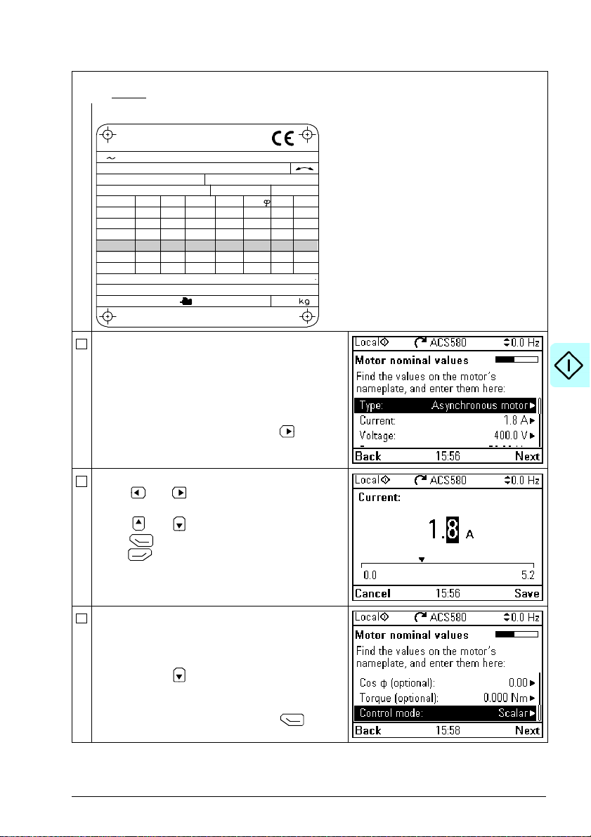
Start-up, control with I/O and ID run 23
M2AA 200 MLA 4
1475
1475
1470
1470
1475
1770
32.5
56
34
59
54
59
0.83
0.83
0.83
0.83
0.83
0.83
3GAA 202 001 - ADA
180
IEC 34-1
6210/C36312/C3
Cat. no
35
30
30
30
30
30
50
50
50
50
50
60
690 Y
400 D
660 Y
380 D
415 D
440 D
V
Hz kW
r/min A
cos
IA/IN
t
E/s
Ins.cl. F
IP 55
No
IEC 200 M/L 55
3
motor
ABB Motors
Refer to the motor nameplate for the following nominal value settings of the motor. Enter the
values exactly
Example of a nameplate of an induction (asynchronous) motor:
Select the motor type.
Check that the motor data is correct. Values are
predefined on the basis of the drive size but you
should verify that they correspond to the motor.
Start with the motor nominal current.
If you have to change the value, go to the edit
view of the selected row by pressing (when
this symbol is shown at the end of the row).
as shown on the motor nameplate.
Set the correct value:
• Use and to move the cursor left and
right.
• Use and to change the value.
Press (Save) to accept the new setting, or
press (Cancel) to go back to the previous
view without making changes.
Continue to check/edit the nominal values and
select scalar or vector control mode.
Motor nominal cos Φ and nominal torque are
optional.
Roll down with
After editing the last row, the panel goes to the
next view.
To go directly to the next view, press (Next).
to see the last row in the view.
Page 24
24 Start-up, control with I/O and ID run
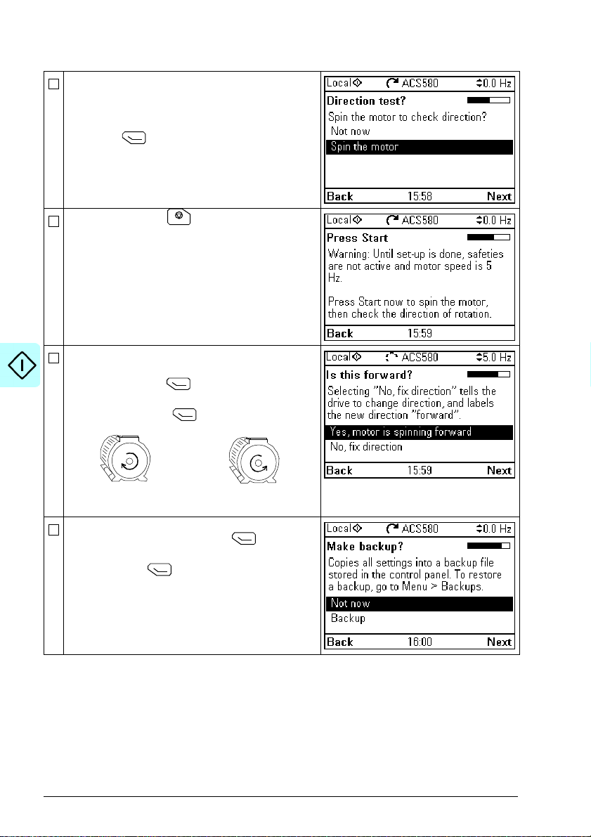
Forward direction Reverse direction
Direction test is optional, and requires rotating the
motor. Do not do this if it could cause any risk, or if
the mechanical set-up does not allow it.
To do the direction test, select Spin the motor
and press (Next).
Press the Start key on the panel to start the
drive.
Check the direction of the motor.
If it is forward, select Yes, motor is spinning
forward and press (Next) to continue.
If the direction is not forward, select No, fix
direction and press (Next) to continue.
If you want to make a backup of the settings made
so far, select Backup and press (Next).
If you do not want to make a backup, select Not
now and press (Next).
Page 25
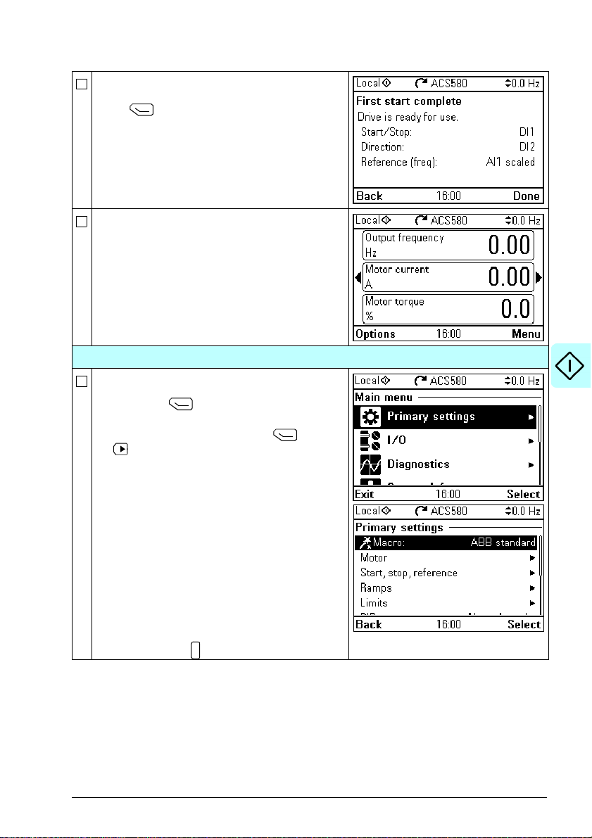
Start-up, control with I/O and ID run 25
?
The first start is now complete and the drive is
ready for use.
Press (Done) to enter the Home view.
The Home view monitoring the values of the
selected signals is shown on the panel.
2 – Additional settings in the Primary settings menu
Make any additional adjustments, for example,
macro, ramps, and limits, starting from the Main
menu – press (Menu) to enter the Main
menu.
Select Primary settings and press
(or ).
ABB recommends that you make at least these
additional settings:
• Choose a macro or set start, stop and reference
values individually
• Ramps
•Limits
With the Primary settings menu, you can also
adjust settings related to the motor, PID, fieldbus,
advanced functions and clock, region and display.
In addition, the menu contains an item to reset the
panel Home view.
To get more information on Primary settings
menu items, press to open the help page.
(Select)
Page 26

26 Start-up, control with I/O and ID run
?
2 – Additional settings: Macro
Select Macro: and press (Select) (or ).
To change the macro in use, select the new macro
and press
changes, press (Back).
Notes:
• Changing macro resets all settings except
• When you change the macro, you also change
• All macros, except the ABB standard (vector)
(Select), or to go back without
motor data to the default values of the selected
macro.
the use of the I/O signals in the drive. Make
sure the actual I/O wiring and the use of I/O in
the control program match each other. You can
check the current I/O use in the I/O menu under
the Main menu (see page 28).
To get information on a selected macro, press
.The help page shows the use of signals and
I/O connections. For detailed I/O connection
diagrams, see chapter Control macros on page
71.
Scroll the page with and .
To return to the Control macro submenu, press
(Exit).
macro, use scalar motor control by default. At
the first start you can select to use scalar or
vector motor control. If you later want to change
the selection, Select Menu - Primary settings -
Motor - Control mode and follow the
instructions.
Page 27
Start-up, control with I/O and ID run 27
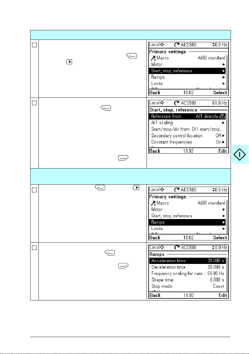
2 – Additional settings: Start, stop and reference values
If you do not wish to use a macro, define the
settings for start, stop and reference:
Select Start, stop, reference and press
(Select) (or ).
Adjust the parameters according to your needs.
Select parameter and press
When you change the settings, you also change
the use of the I/O signals in the drive. Make sure
the actual I/O wiring and the use of I/O in the
control program match each other. You can check
the current I/O use in the I/O menu under the
Main menu (see page 28).
After making the adjustments, go back to the
Primary settings menu by pressing
(Back).
(Select).
2 – Additional settings: Ramps
(acceleration and deceleration times for the motor)
Select Ramps and press (Select) (or ).
Adjust the parameters according to your needs.
Select a parameter and press
After making the adjustments, go back to the
Primary settings menu by pressing
(Back).
(Edit).
Page 28
28 Start-up, control with I/O and ID run
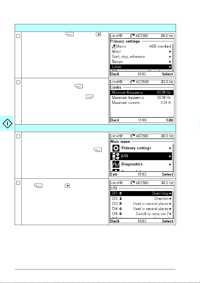
2 – Additional settings: Limits
Select Limits and press (Select) (or ).
Adjust the parameters according to your needs.
Select a parameter and press
After making the adjustments, go back to the
Primary settings menu by pressing
(Back).
(Select).
3 – I/O menu
After the additional adjustments, make sure that
the actual I/O wiring matches the I/O use in the
control program.
In the Main menu, select a I/O and press
(Select) to enter the I/O menu.
Select a the connection you want to check and
press
(Select) (or ).
Page 29
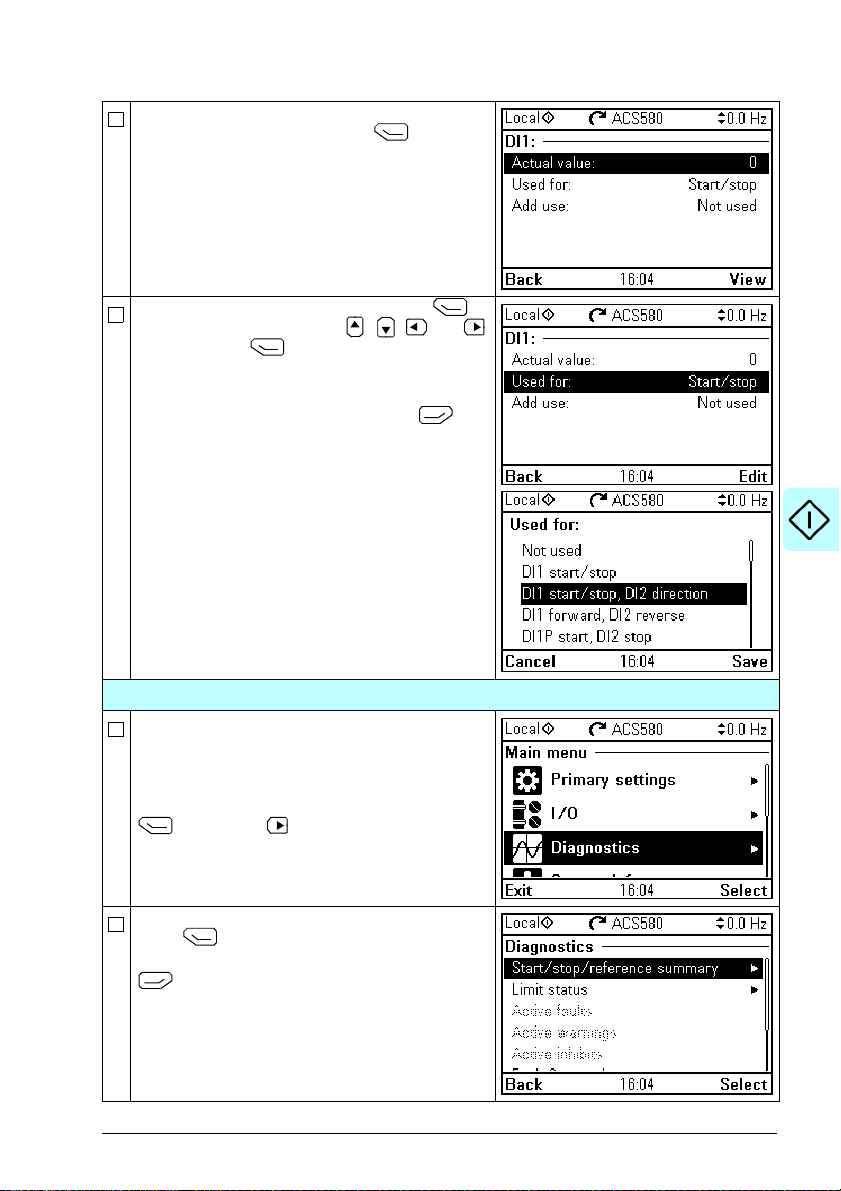
Start-up, control with I/O and ID run 29
To view the details of a parameter that cannot be
adjusted via the I/O menu, press
(View).
To adjust the value of a parameter, press
(Edit), adjust the value using , , and
keys and press
wiring must match the new value.
Go back to the Main menu by pressing
(Back) repeatedly.
(Save). Note that the actual
4 – Diagnostics menu
After making the additional adjustments and
checking the I/O connections, use the
Diagnostics menu to make sure that the setup is
functioning correctly.
In the Main menu, select Diagnostics and press
(Select) (or ).
Select the diagnostics item you want to view and
press (Select).
Return to the Diagnostics menu by pressing
(Back).
Page 30
30 Start-up, control with I/O and ID run
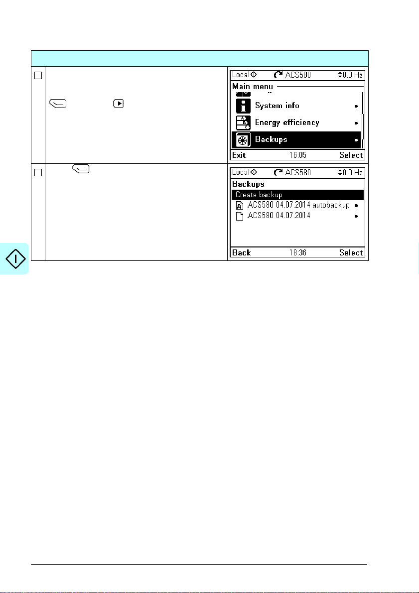
5 – Backup
After you have finished start-up ABB recommends
that you make a backup.
In the Main menu, select Backups and press
(Select) (or ).
Press
(Select) to start backup.
Page 31

Start-up, control with I/O and ID run 31
Loc/Rem
How to control the drive through the I/O interface
The table below describes how to operate the drive through the digital and analog
inputs when:
• the motor start-up is performed, and
• the default parameter settings of the ABB standard macro are in use.
Preliminary settings
If you need to change the direction of rotation, check
that limits allow reverse direction: Go to Menu -
Primary settings - Limits and make sure that the
minimum limit has a negative value and the maximum
limit has a positive value.
Make sure that the control connections are wired
according to the connection diagram given for the ABB
standard macro.
Make sure that the drive is in remote control. Press
key
to switch between remote and local
control.
Starting and controlling the speed of the motor
Start by switching digital input DI1 on.
The arrow starts rotating. It is dotted until the setpoint
is reached.
Regulate the drive output frequency (motor speed) by
adjusting voltage of analog input AI1.
See section ABB standard macro on
page 72.
In remote control, the panel display
shows text Remote at the top left.
Changing the direction of the motor rotation
Reverse direction: Switch digital input DI2 on.
Forward direction: Switch digital input DI2 off.
Page 32

32 Start-up, control with I/O and ID run
Stopping the motor
Switch digital input DI1 off. The arrow stops rotating.
Page 33

Start-up, control with I/O and ID run 33
How to perform the ID run
The drive automatically estimates motor characteristics using Standstill ID run when
the drive is started for the first time in vector control and after any motor parameter
(group 99 Motor data) is changed. This is valid when
• parameter 99.13 ID run requested selection is Standstill and
• parameter 99.04 Motor control mode selection is Vector.
In most applications there is no need to perform a separate ID run. The ID run should
be selected manually if:
• vector control mode is used (parameter 99.04 Motor control mode is set to
Vector), and
• permanent magnet motor (PM) is used (parameter 99.03 Motor type is set to
Permanent magnet motor), or
• synchronous reluctance motor (SynRM) is used (parameter 99.03 Motor type is
set to SynRM), or
• drive operates near zero speed references, or
• operation at torque range above the motor nominal torque, over a wide speed
range is needed.
Do the ID run with the ID run assistant by selecting Menu - Primary settings - Motor
- ID run (see page 34) or with parameter 99.13 ID run requested (see page 36).
Note: If motor parameters (group 99 Motor data) are changed after the ID run, it must
be repeated.
Note: If you have already parameterized your application using the scalar motor
control mode (99.04 Motor control mode is set to Scalar) and you need to change
motor control mode to Vector,
• change the control mode to vector with the Control mode assistant (go to Menu -
Primary settings - Motor - Control mode) and follow the instructions. The ID run
assistant then guides you through the ID run.
or
• set parameter 99.04 Motor control mode to Ve cto r , and
• for I/O controlled drive, check parameters in groups 22 Speed reference
selection, 23 Speed reference ramp, 12 Standard AI, 30 Limits
Monitoring/scaling settings.
• for torque controlled drive, check also parameters in group 26 Torque
reference chain.
and 46
Page 34

34 Start-up, control with I/O and ID run
Loc/Rem
ID run procedure
With the ID run assistant
Pre-check
WARNING!
speed during the ID run. The motor will rotate in the forward direction. Make
sure that it is safe to run the motor before performing the ID run.
Do not do ID run on a rotating motor. Make sure that the motor is stopped
before starting the ID run.
De-couple the motor from the driven equipment
Check that the values of the motor data parameters are equivalent to those on the motor
nameplate.
Check that the STO circuit is closed.
The assistant will ask if you want to use temporary motor limits. They must meet the
following conditions:
Minimum speed <
Maximum speed = motor rated speed (Normal ID run procedure needs the motor to be
run at 100% speed.)
Maximum current > I
Maximum torque > 50%
Make sure that the panel is in local control (text Local shown at the top left). Press key
to switch between local and remote control.
Go to the Main menu by pressing (Menu)
in the Home view.
Select Primary settings and press
(Select) (or ).
The motor will run at up to approximately 50…80% of the nominal
0rpm
HD
ID run
Select Motor and press
(Select) (or ).
Page 35

Start-up, control with I/O and ID run 35
Select ID run (shown only when the drive is in
vector control mode) and press
).
Select the type of ID run you want to do and
press
(Select) (or ).
Warning message Identification run is shown at
the top for a few seconds.
Panel LED starts blinking green to indicate an
active warning.
Check the motor limits shown on the panel. If you
need other limits during the ID run you can enter
them here. The originals limits will be restored
after the ID run.
Press
(Next).
Press the start key
In general, ABB recommends not to press any
control panel keys during the ID run. However,
you can stop the ID run at any time by pressing
the stop key
During the ID run a progress view is shown.
After the ID run is completed, text ID run done is
shown. The LED stops blinking.
If the ID run fails, fault FF61 ID run is shown. See
chapter Fault tracing on page 407 for more
information.
() to start the ID run.
().
( Select) (or
Page 36

36 Start-up, control with I/O and ID run
Loc/Rem
With parameter 99.13 ID run requested
Pre-check
WARNING!
speed during the ID run. The motor will rotate in the forward direction. Make
sure that it is safe to run the motor before performing the ID run.
Do not do ID run on a rotating motor. Make sure that the motor is stopped
before starting the ID run.
De-couple the motor from the driven equipment
Check that the values of the motor data parameters are equivalent to those on the motor
nameplate.
Check that the STO circuit is closed.
If parameter values (from group 10 Standard DI, RO to group 99 Motor data) are changed
before the ID run, check that the new settings meet the following conditions:
30.11 Minimum speed <
30.12 Maximum speed = motor rated speed (Normal ID run procedure needs the motor to
be run at 100% speed.)
30.17 Maximum current > I
30.20 Maximum torque 1 > 50% or 30.24 Maximum torque 2 > 50%, depending on which
torque limit set is in use according to parameter 30.18 Torq lim sel.
Check that signals
run enable (parameter 20.12 Run enable 1 source) is active
start enable (parameter 20.19 Enable start command) is active
enable to rotate (parameter 20.22 Enable to rotate) is active.
Make sure that the panel is in local control (text Local shown at the top left). Press key
to switch between local and remote control.
The motor will run at up to approximately 50…80% of the nominal
0rpm
HD
ID run
Go to the Main menu by pressing (Menu)
in the Home view.
Press .
Page 37

Start-up, control with I/O and ID run 37
Select Parameters and press (Select) (or
).
Select Complete list and press
(or ).
Scroll the page with and , and select
parameter group 99 Motor data and press
(Select) (or ).
Scroll the page with and , and select
parameter 99.13 ID run requested (99.13 ID run
requested) and press
(Select) (or ).
(Select)
Select the ID run type and press
).
(Save) (or
Page 38

38 Start-up, control with I/O and ID run
The panel returns to the previous view and
warning message Identification run is shown at
the top for a few seconds.
Panel LED starts blinking green to indicate an
active warning (AFF6).
The AFF6 warning view is shown when no key
has been pressed for one minute. Pressing
(How to fix) shows text informing that the ID run
will be done at the next start. You can hide the
warning view by pressing (Hide).
Press the start key
In general, ABB recommends not to press any
control panel keys during the ID run. However,
you can stop the ID run at any time by pressing
the stop key
During the ID run the arrow is rotating at the top.
After the ID run is completed, text ID run done is
shown. The LED stops blinking.
If the ID run fails, fault FF61 ID run is shown. See
chapter Fault tracing on page 407 for more
information.
() to start the ID run.
().
Page 39

Control panel 39
3
1a
1b
Control panel
Contents of this chapter
This chapter contains instructions for removing and reinstalling the assistant control
panel and briefly describes its display, keys and key shortcuts. For more information,
see ACX-AP-x assistant control panels user’s manual (3AUA0000085685 [English]).
Removing and reinstalling the control panel
To remove the control panel, press the retaining clip at the top (1a) and pull it forward
from the top edge (1b).
Page 40

40 Control panel
1a
1b
1c
4
3
6
7 8
5
10
2
9
1
To reinstall the control panel, put the bottom of the container in position (1a), press
the retaining clip at the top (1b) and push the control panel in at the top edge (1c).
Layout of the control panel
1 Layout of the control panel display 6 The arrow keys
2 Left softkey 7Stop (see Start and Stop)
3 Right softkey 8 Start (see Start and Stop)
4 Status LED, see chapter Maintenance
and hardware diagnostics, section
LEDs in the Hardware manual of the
drive.
5 Help 10 USB connector
9 Local/Remote (see Loc/Rem)
Page 41

Layout of the control panel display
1
51
2
4
6
7 78
13
In most views, the following elements are shown on the display:
Control panel 41
1. Control location and related icons: Indicates how the drive is controlled:
• No text: The drive is in local control, but controlled from another device. The
icons in the top pane indicate which actions are allowed:
Text/Icons Starting from this
• Local: The drive is in local control, and controlled from this control panel. The
icons in the top pane indicate which actions are allowed:
Text/Icons Starting from this
Local
control panel
Not allowed Not allowed Not allowed
control panel
Allowed Allowed Allowed
Stopping from this
control panel
Stopping from this
control panel
Giving reference
from this panel
Giving reference
from this panel
Page 42

42 Control panel
• Remote: The drive is in remote control, ie, controlled through I/O or fieldbus.
The icons in the top pane indicate which actions are allowed with the control
panel:
Text/Icons Starting from this
Remote
Remote
Remote
Remote
control panel
Not allow ed Not allowed Not allowed
Allowed Allowed Not allowed
Not allowed Allowed Allowed
Allowed Allowed Allowed
Stopping from this
control panel
Giving reference
from this panel
2. Panel bus: Indicates that there are more than one drive connected to this panel.
To switch to another drive, go to Options - Select drive.
3. Status icon: Indicates the status of the drive and the motor. The direction of the
arrow indicates forward (clockwise) or reverse (counter-clockwise) rotation.
Status icon Animation Drive status
-
- Stopped, start inhibited
Blinking Stopped, start command given but start inhibited. See
Blinking Faulted
Blinking Running, at reference, but the reference value is 0
Rotating Running, not at reference
Rotating Running, at reference
- Pre-heating (motor heating) active
- PID sleep mode active
Stopped
Menu - Diagnostics on the control panel
4. Drive name: If a name has been given, it is displayed in the top pane. By default,
it is “ACS580”. You can change the name on the control panel by selecting Menu
- Primary settings - Clock, region, display (see page 61).
5. Reference value: Speed, frequency, etc. is shown with its unit. For information on
changing the reference value in the Primary settings menu (see page 46).
6. Content area: The actual content of the view is displayed in this area. The
content varies from view to view. The example view on page 41 is the main view
of the control panel which is called the Home view.
7. Softkey selections: Displays the functions of the softkeys (
and ) in a
given context.
8. Clock: The clock displays the current time. You can change the time and time
format on the control panel by selecting Menu - Primary settings - Clock,
region, display (see page 61).
Page 43

Control panel 43
?
Loc/Rem
You can adjust the display contrast and back light functionality on the control panel by
selecting Menu - Primary settings - Clock, region, display (see page 61).
Keys
The keys of the control panel are described below.
Left softkey
The left softkey ( ) is usually used for exiting and canceling. Its function in a given
situation is shown by the softkey selection in the bottom left corner of the display.
Holding down exits each view in turn until you are back in the Home view. This
function does not work in special screens.
Right softkey
The right softkey ( ) is usually used for selecting, accepting and confirming. The
function of the right softkey in a given situation is shown by the softkey selection in
the bottom right corner of the display.
The arrow keys
The up and down arrow keys ( and ) are used to highlight selections in menus
and selection lists, to scroll up and down on text pages, and to adjust values when,
for example, setting the time, entering a passcode or changing a parameter value.
The left and right arrow keys ( and ) are used to move the cursor left and right in
parameter editing and to move forward and backward in assistants. In menus, and
function the same way as
Help
The help key (
words, the content of the page is relevant to the menu or view in question.
Start and Stop
In local control, the start key ( ) and the stop key ( ) start and stop the drive,
respectively.
Loc/Rem
The location key ( ) is used for switching the control between the control panel
(Local) and remote connections (Remote). When switching from Remote to Local
while the drive is running, the drive keeps running at the same speed. When
switching from Local to Remote, the status of the remote location is adopted.
) opens a help page. The help page is context-sensitive, in other
and , respectively.
Page 44

44 Control panel
Key shortcuts
The table below lists key shortcuts and combinations. Simultaneous key presses are
indicated by the plus sign (+).
Shortcut Available in Effect
+
+
+ ,
+
+ ,
+
or Home view Adjust reference.
+ parameter edit views Revert an edit able parameter to its default value.
+ view showing a list
(keep down)
any view Save a screenshot. Up to fifteen images may be stored
in the control panel memory.
To transfer images to PC, connect the assistant control
panel to PC with a USB cable and the panel will mount
itself as an MTP (media transfer protocol) device.
Pictures are stored in the screen shots folder.
For more instructions, see ACX-AP-x assistant control
panels user’s manual (3AUA0000085685 [English]).
any view Adjust backlight brightness.
any view Adjust display contrast.
Show/hide selection index numbers.
of selections for a
parameter
any view Return to the Home view by pressing down the key until
the Home view is shown.
Page 45

Settings, I/O and diagnostics on the control panel 45
4
Settings, I/O and diagnostics on the control panel
Contents of this chapter
This chapter provides detailed information about the Primary settings, I/O and
Diagnostics menus on the control panel.
To get to the Primary settings, I/O or Diagnostic menu from the Home view, first
select Menu to go the Main menu, and in the Main menu, select Primary settings,
I/O or Diagnostics.
Page 46

46 Settings, I/O and diagnostics on the control panel
?
Primary settings menu
To go the Primary settings menu from the Home view, select Menu - Primary
settings.
The Primary settings menu enables you to adjust and define additional settings
used in the drive.
After making the guided settings using the first start assistant, ABB recommends that
you make at least these additional settings:
• Select a Macro or set Start, stop, reference values
• Ramps
• Limits
With the Primary settings menu, you can also adjust settings related to the motor,
PID, fieldbus, advanced functions and clock, region and display. In addition, you can
reset the fault and event logs, panel Home view, parameters not related to hardware,
fieldbus settings, motor data and ID run results, all parameters, end user texts as well
as reset everything to factory defaults. Note that the Primary settings menu only
enables you to modify some of the settings: more advanced configuration is done via
the parameters: Select Menu - Parameters. For more information on the different
parameters, see chapter Parameters on page 157.
In the Setting menu, the symbol indicates multiple connected signals/parameters.
The symbol indicates that the setting provides an assistant when modifying the
parameters.
To get more information on Primary settings menu items, press the
the help page.
key to open
Page 47

Settings, I/O and diagnostics on the control panel 47
…
The figure below shows how to navigate in the Primary settings menu.
Page 48

48 Settings, I/O and diagnostics on the control panel
The sections below provide detailed information about the contents of the different
submenus available in the Primary settings menu.
Macro
Use the Macro submenu to quickly set up drive control and reference source by
selecting from a set of predefined wiring configurations.
Note: For detailed information about the available macros, see Control macros on
page 45.
If you do not wish to use a macro, manually define the settings for Start, stop,
reference. Note that even if you select to use a macro, you can also modify the other
settings to suit your needs.
Motor
Use the Motor submenu to adjust motor-related settings, such as nominal values,
control mode or thermal protection.
Note that settings that are visible depend on other selections, for example vector or
scalar control mode, used motor type or selected start mode.
Three assistants are available: Control mode, Nominal value and ID run (for vector
control mode only).
Page 49

Settings, I/O and diagnostics on the control panel 49
The table below provides detailed information about the available setting items in the
Motor menu.
Menu item Description Corresponding
Control mode Selects whether to use scalar or vector control
mode.
For information on scalar control mode, see Speed
compensated stop on page 136.
For information on vector control mode, see Rush
control on page 133.
Nominal values Enter the motor's nominal values from the motor's
nameplate.
Thermal protection
estimated
The settings in this submenu are meant to pr otect
the motor from overheating by automatically
triggering a fault or warning above a certain
temperature.
By default, motor thermal estimate protection is on.
ABB recommends checking the values for the
protection to function properly.
For more information, see Motor thermal protection
on page 142.
Thermal protection
measured
The settings in this submenu are meant to pr otect
the motor with a thermal measurement from
overheating by automatically triggering a fault or
warning above a certain temperature.
For more information, see Motor thermal protection
on page 142.
Start mode: Sets how the drive starts the motor (e.g. pre-
magnetize or not).
Flux braking: Sets how much current to use for braking, ie. how
the motor is magnetized before starting. For more
information, see Flux braking on page 129.
U/f ratio: The form of voltage to frequency ratio below field
weakening point. For more information, see Speed
compensated stop on page 136.
IR compensation: Sets how much to boost voltage at zero speed.
Increase this for higher break-away torque. For
more information, see IR compensation for scalar
motor control on page 127.
Pre-heating Turns pre-heating on or off. The drive can prevent
condensation in a stopped motor by feeding it a
fixed current (% of motor nominal current). Use in
humid or cold conditions to prevent condensation.
Phase order: If the motor turns in the wrong direction, change
this setting to fix the direction instead of changing
the phase order on the motor cable.
parameter
99.04 Motor control
mode
99.06 Motor nominal
current …
99.12 Motor nominal
torque
35 Motor thermal
protection
35 Motor thermal
protection
21 Start/stop mode
97.05 Flux braking
97.20 U/F ratio
97.13 IR compensation
21.14 Pre-heating input
source
21.16 Pre-heating
current
99.16 Motor phase order
Page 50

50 Settings, I/O and diagnostics on the control panel
Start, stop, reference
Use the Start, stop, reference submenu to set up start/stop commands, reference,
and related features, such as constant speeds or run permissions.
The table below provides detailed information about the available setting items in the
Start, stop, reference menu.
Menu item Description Corresponding
Reference from Sets where the drive gets its reference when
remote control (EXT1) is active.
Reference-related
settings (e.g. AI
The voltage or current fed to the input is converted
into a value the drive can use (e.g. reference).
scaling, AI2 scaling,
Motor potentiometer
settings) depending
on the selected
reference
Start/stop/dir from: Sets where the drive gets start, stop, and
(optionally) direction commands when remote
control (EXT1) is active.
Secondary control
location
Settings for the secondary remote control location,
EXT2. These settings include reference source,
start, stop, direction and command sources for
EXT2.
By default, EXT2 is set to Off.
parameter
28.11 Ext1 frequency
ref1 or
22.11 Ext1 speed ref1
12.19 AI1 scaled at AI1
min
12.20 AI1 scaled at AI1
max
20.01 Ext1 commands
19.11 Ext1/Ext2
selection
28.15 Ext2 frequency
ref1 or
22.18 Ext2 speed ref1
12.17 AI1 min
12.18 AI1 max
12.27 AI2 min
12.28 AI2 max
20.06 Ext2 commands
20.08 Ext2 in1 source
20.09 Ext2 in2 source
20.10 Ext2 in3 source
Page 51

Settings, I/O and diagnostics on the control panel 51
Menu item Description Corresponding
Constant speeds /
Constant frequencies
These settings are for using a constant value as
the reference. By default, this is set to On. For
more information, see Constant
speeds/frequencies on page 112 .
Jogging These settings allow you to use a digital input to
briefly run the motor using predefined speed and
acceleration/deceleration ramps. By default,
jogging is disabled and it can only be used in the
Vector control mode. For more information, see
parameter
28.21 Constant
frequency function or
22.21 Constant speed
function
28.26 Constant
frequency 1
28.27 Constant
frequency 2
28.28 Constant
frequency 3
22.26 Constant speed 1
22.27 Constant speed 2
22.28 Constant speed 3
20.25 Jogging enable
22.42 Jogging 1 ref
22.43 Jogging 2 ref
23.20 Acc time jogging
23.21 Dec time jogging
Jogging on page 134.
Run permissions Settings to prevent the drive from running or
starting when a specific digital input is low.
20.12 Run enable 1
source
20.11 Run enable stop
mode
20.19 Enable start
command
20.22 Enable to rotate
21.05 Emergency stop
source
21.04 Emergency stop
mode
23.23 Emergency stop
time
Ramps
Use the Ramps submenu to set up acceleration and deceleration settings.
Note: To set ramps, you also have to specify parameter 46.01 Speed scaling (in
speed control mode) or 46.02 Frequency scaling (in frequency control mode).
Page 52

52 Settings, I/O and diagnostics on the control panel
The table below provides detailed information about the available setting items in the
Ramps menu.
Menu item Description Corresponding
Acceleration time: This is the time between standstill and “scaling
speed” when using the default ramps (set 1).
Deceleration time: This is the time between standstill and “scaling
speed” when using the default ramps (set 1).
Frequency scaling
for ramps:
This is the he maximum speed/frequency value for
acceleration ramp rate and the initial value for
deceleration ramp rate. Applies to both ramp sets.
Shape time: Sets the shape of the default ramps (set 1).
Stop mode: Sets how the drive stops the motor.
Use two ramp sets Sets the use of a second acceleration/deceleration
ramp set. If unselected, only one ramp set is used.
Note that if this selection is not enabled, the
selection below are not available.
Activate ramp set 2: To switch ramp sets, you can either:
• use a digital input (low = set 1; high = set 2), or
• automatically switch to set 2 above a certain
frequency/speed.
Acceleration time 2: Sets the time between standstill and “scaling
speed” when using ramp set 2.
Deceleration time 2: Sets the time between standstill and “scaling
speed” when using ramp set 2.
Shape time 2: Sets the shape of ramps in set 2.
parameter
23.12 Acceleration time
1
28.72 Freq acceleration
time 1
23.13 Deceleration time
1
28.73 Freq deceleration
time 1
46.02 Frequency scaling
23.32 Shape time 1
28.82 Shape time 1
21.03 Stop mode
23.11 Ramp set
selection
28.71 Freq ramp set
selection
23.14 Acceleration time
2
28.74 Freq acceleration
time 2
23.15 Deceleration time
2
28.75 Freq deceleration
time 2
23.33 Shape time 2
28.83 Shape time 2
Page 53

Settings, I/O and diagnostics on the control panel 53
Limits
Use the Limits submenu to set the allowed operating range. This function is intended
to protect the motor, connected hardware and mechanics. The drive stays within
these limits, no matter what reference value it gets.
Note: To set ramps, you also have to specify parameter 46.01 Speed scaling (in
speed control mode) or 46.02 Frequency scaling (in frequency control mode); these
limit parameters have no effect on ramps.
The table below provides detailed information about the available setting items in the
Limits menu.
Menu item Description Corresponding
Minimum frequency Sets the minimum operating frequency. Affects
scalar control only.
Maximum frequency Sets the maximum operating frequency. Affects
scalar control only.
Minimum speed Sets the minimum operating speed. Affects vector
control only.
Maximum speed Sets the maximum operating speed. Affects vector
control only.
Minimum torque Sets the minimum operating torque. Affects vector
control only.
Maximum torque Sets the maximum operating torque. Affects vector
control only.
Maximum current Sets the maximum output current.
parameter
30.13 Minimum
frequency
30.14 Maximum
frequency
30.11 Minimum speed
30.12 Maximum speed
30.19 Minimum torque 1
30.20 Maximum torque
1
30.17 Maximum current
Page 54

54 Settings, I/O and diagnostics on the control panel
PID
The PID submenu contains settings and actual values for the process PID controller
for controlling multiple pumps or fans through the drive's relay outputs.
The table below provides detailed information about the available setting items in the
PID menu.
Menu item Description Corresponding
PID controls: Sets what to use PID output for:
• Not selected: PID not used.
• Frequency reference (or Speed reference,
depending on the motor control mode): Uses
PID output as a frequency (speed) reference
when remote control (EXT1) is active.
PID output: View the process PID output or set its range.
Unit: PID customer unit. Sets the text shown as the unit
for setpoint, feedback and deviation.
Deviation: View or invert process PI D deviation.
Setpoint: View or configure the process PID setpoint, ie. the
target process value.
You can also use a constant setpoint value instead
of (or in addition to) an external setpoint source.
When a constant setpoint is active, it overrides the
normal setpoint.
Feedback: View or configure process PID feedback, ie. the
measured value.
parameter
40.07 Process PID
operation mode
40.01 Process PID
output actual
40.36 Set 1 output min
40.37 Set 1 output ma x
40.04 Process PID
deviation actual
40.31 Set 1 deviation
invers ion
40.03 Process PID
setpoint actual
40.16 Set 1 setpoint 1
source
40.02 Process PID
feedback actual
40.08 Set 1 feedback 1
source
40.11 Set 1 feedback
filter time
Page 55

Settings, I/O and diagnostics on the control panel 55
Menu item Description Corresponding
Tuning The Tun ing submenu contains settings for gain,
integration time and derivation time.
1. Make sure it is safe to start the motor and run the
actual process.
2. Start the motor in remote control.
3. Change setpoint by a small amount.
parameter
40.32 Set 1 gain
40.33 Set 1 integration
time
40.34 Set 1 derivation
time
40.35 Set 1 derivation
filter time
4. Watch how feedback reacts.
5. Adjust gain/integration/derivation.
6. Repeat steps 3-5 until feedback reacts as
desired.
Sleep function The sleep function can be used to save energy by
stopping the motor during low demand. By default,
sleep function is disabled. If d, the motor
automatically stops when demand is low, and starts
again when deviation grows too large. This saves
energy when rotating the motor at low speeds
would be useless.
See section Sleep and boost functions for process
PID control on page 116.
40.43 Set 1 sleep level
40.44 Set 1 sleep delay
40.45 Set 1 sleep boost
time
40.46 Set 1 sleep boost
step
40.47 Set 1 wake-up
deviation
40.48 Set 1 wake-up
delay
Pump and fan control
The Pump and fan control submenu contains settings for the Pump and fan control
logic. The Pump and fan control is supported in external control location EXT2 only.
The table below provides detailed information about the available setting items in the
Pump and fan control menu.
Menu item Description Corresponding
PFC mode: See section Pump and fan control (PFC) on page
118.
Selects the PFC or SPFC control.
parameter
76.21 Multipump
configuration
Page 56

56 Settings, I/O and diagnostics on the control panel
Menu item Description Corresponding
Configure PFC I/O Configures PFC/SPFC I/O.
•ROs
• Interlocks
• Check I/O configuration (See I/O menu on page
64.)
Configure PFC
Configures PFC/SPFC control
control
Configure
Configures Autochange
Autochange
parameter
76.25 Number of mot ors
76.27 Max number of
motors allowed
76.59 PFC contactor
delay
10.24 RO1 source
10.27 RO2 source
10.30 RO3 source
76.81 PFC 1 interlock
76.82 PFC 2 interlock
76.83 PFC 3 interlock
76.84 PFC 4 interlock
76.30 Start point 1
76.31 Start point 2
76.32 Start point 3
76.41 Stop point 1
76.42 Stop point 2
76.43 Stop point 3
76.55 Start delay
76.56 Stop delay
76.70 PFC autochange
76.71 PFC autochange
interval
76.72 Maximum wea r
imbalance
76.73 Autochange level
Page 57

Settings, I/O and diagnostics on the control panel 57
Fieldbus
Use the settings in the Fieldbus submenu to use the drive with a fieldbus:
• CANopen
• ControlNet
• DeviceNet
• ETH Pwrlink (Ethernet POWERLINK)
•EtherCAT
• Ethernet/IP
• RS-485
• Modbus (RTU or TCP)
• PROFIBUS DP
• PROFINET IO
TM
TM
You can also configure all the fieldbus related settings via the parameters (parameter
groups 50 Fieldbus adapter (FBA), 51 FBA A settings, 52 FBA A data in, 53 FBA A
data out, 58 Embedded fieldbus), but the purpose of the Fieldbus menu is to make
the protocol configurations easier.
Note that only Modbus RTU is embedded and the other fieldbus modules are optional
adapters. For the optional modules, the following adapters are required to the needed
protocols:
• CANopen: FCAN-01
• ControlNet: FCNA-01
• DeviceNet
TM
: FDNA-01
• ETH Pwrlink (Ethernet POWERLINK): FEPL-02
• EtherCAT: FECA-01
TM
• Ethernet/IP
: FENA-11/-21
• Modbus/TCP: FENA-11/-21
• RS-485: FSCA-01
• PROFIBUS DP: FBPA-01
• PROFINET IO: FENA-11/-21
Page 58

58 Settings, I/O and diagnostics on the control panel
The table below provides detailed information about the available setting items in the
Fieldbus menu. Note that some of the items only become active once you have
enabled fieldbus.
Menu item Description Corresponding
Fieldbus selection Select this if you want to use the drive with a
Communication
setup
Drive control setup Sets how a fieldbus master can control this drive,
Received data from
master
fieldbus.
To set up communication between the drive and
the fieldbus master, define these settings and then
select Apply settings to fieldbus module.
and how the drive reacts if the fieldbus
communication fails.
Sets what the drive's fieldbus module expects to
receive from the fieldbus master (PLC). After
changing these sett ings, select Apply settings to
fieldbus module.
parameter
51.01 FBA A type
58.01 Protocol enable
51 FBA A settings
51.01 FBA A type
51.02 FBA A Par2
51.27 FBA A par refresh
51.31 D2FBA A comm
status
50.13 FBA A control
word
50.16 FBA A status
word
58 Embedded fieldbus
58.01 Protocol enable
58.03 Node address
58.04 Baud rate
58.05 Parity
58.25 Control profile
20.01 Ext1 commands
19.11 Ext1/Ext2
selection
22.11 Ext1 speed ref1
28.11 Ext1 frequency
ref1
22.41 Speed ref safe
28.41 Frequency ref
safe
50.03 FBA A comm loss
t out
46.01 Speed scaling
46.02 Frequency scaling
23.12 Acceleration time
1
23.13 Deceleration time
1
28.72 Freq acceleration
time 1
28.73 Freq deceleration
time 1
51.27 FBA A par refresh
58.14 Communication
loss action
58.15 Communication
loss mode
58.16 Communication
loss time
50.13 FBA A control
word
53 FBA A data out
51.27 FBA A par refresh
58.18 EFB control word
03.09 EFB reference 1
Page 59

Settings, I/O and diagnostics on the control panel 59
Menu item Description Corresponding
Send data to master Sets what the drive's fieldbus module sends to the
fieldbus master (PLC). After changing these
settings, select Apply settings to fieldbus
module.
Apply settings to
Applies modified settings to the fieldbus module.
fieldbus module
parameter
50.16 FBA A status
word
52 FBA A data in
51.27 FBA A par refresh
58.19 EFB status word
51.27 FBA A par refresh
58.06 Communication
control
Advanced functions
The Advanced functions submenu contains settings for advanced functions, such
as triggering or resetting faults via I/O, signal supervision, using the drive with timed
functions, or switching between several entire sets of settings.
The table below provides detailed information about the available setting items in the
Advanced functions menu.
Menu item Description Corresponding
External events Enables you to define custom faults or warnings
you can trigger via digital input. The texts of these
messages are customizable.
Additional fault reset You can reset an active fault via I/O: a rising pulse
in the selected input means reset.
A fault can be reset from the fieldbus even if Reset
faults manually is unselected.
Reset from keypad
and...
Define from where you want to reset faults
manually. Note that this submenu is active only if
you have selected to reset faults manually.
parameter
31.01 External event 1
source
31.02 External event 1
type
31.03 External event 2
source
31.04 External event 2
type
31.05 External event 3
source
31.06 External event 3
type
31.11 Fault reset
selection
31.11 Fault reset
selection
Page 60

60 Settings, I/O and diagnostics on the control panel
Menu item Description Corresponding
Autoreset faults Reset faults automatically. For more information,
see Automatic fault resets on page 148.
Supervision You can select three signals to be supervised. If a
signal is outside predefined limits a fault or warning
is generated. For complete settings, see group 32
Supervision on page 268.
Stall pr otection The drive can detect a motor stall and
automatically fault or show a warning message.
Stall condition is detected when:
• current is high (above certain % of motor
nominal current), and
parameter
31.12 Autoreset
selection
31.14 Number of trials
31.15 Total trials time
31.16 Delay time
32.01 Supervision
status
32.05 Supervision 1
function
32.06 Supervision 1
action
32.07 Supervision 1
signal
32.09 Supervision 1 low
32.10 Supervision 1
high
32.11 Supervision 1
hysteresis
…
32.25 Supervision 3
function
32.26 Supervision 3
action
32.27 Supervision 3
signal
32.29 Supervision 3 low
32.30 Supervision 3
high
32.31 Supervision 3
hysteresis
31.24 Stall function
31.25 Stall current limit
31.26 Stall speed limit
31.27 Stall frequency
limit
31.28 Stall time
• output frequency (scalar control) or motor speed
(vector control) is below a certain limit, and
• the conditions above have been true for a certain
minimum duration.
Page 61

Settings, I/O and diagnostics on the control panel 61
Menu item Description Corresponding
Timed functions Enables using the drive with timed functions. For
complete settings, see group 34 Timed functions
on page 275.
User sets This submenu enables you to save multiple sets of
settings for easy switching. For more information
about user sets, see User parameter sets on page
154.
parameter
34.100 Timed function 1
34.101 Timed function 2
34.102 Timed function 3
34.11 Timer 1
configuration
34.12 Timer 1 start time
34.13 Timer 1 duration
…
34.44 Timer 12
configuration
34.45 Timer 12 start
time
34.46 Timer 12 duration
34.111 Boost time
activation source
34.112 Boost time
duration
96.11 User set
save/load
96.10 User set status
96.12 User set I/O mode
in1
96.13 User set I/O mode
in2
Clock, region, display
The Clock, region, display submenu contains settings for language, date and time,
display (such as brightness) and settings for changing how information is displayed
on screen.
The table below provides detailed information about the available setting items in the
Clock, region, display menu.
Menu item Description Corresponding
Language Change the language used on the control panel
screen. Note that the language is loaded from the
drive so this takes some time.
Date & time Set the time and date, and their formats.
Units Select the units used for power, temperature and
torque.
parameter
96.01 Language
Page 62

62 Settings, I/O and diagnostics on the control panel
Menu item Description Corresponding
parameter
Drive name: The drive name defined in this setting is shown in
the status bar at the top of the screen while using
the drive. If more than one drives are connected to
the control panel, the drive names make it easy to
identify each drive. It also identifies any backups
you create for this drive.
Contact info in fault
view
Define a fixed text that is shown during any fault
(for example, who to contact in case of a fault).
If a fault occurs, this information appears on the
panel screen (in addition to the fault- specific
information).
Display settings Adjust the brightness, contrast and display power
save delay of the panel screen or to invert white
and black.
Show in lists Show or hide the numeric IDs of:
• parameters and groups
• option list items
•bits
• devices in Options > Select drive
Show inhibit pop-up Enables or disables pop-up views showing
information on inhibits, for example when you try to
start the drive but it is prevent ed.
Reset to defaults
The Reset to defaults submenu enables you to reset parameters and other settings.
Menu item Description Corresponding
Reset fault and event
logs
Reset home view
layout
Clears all events from the drive’s fault and event
logs.
Restores the Home view layout back to show the
values of the default parameters defined by the
control macro in use.
parameter
96.51 Clear fault and
event logger
96.06 Parameter
restore, selection Reset
home view
Page 63

Settings, I/O and diagnostics on the control panel 63
Menu item Description Corresponding
Reset non-HW
parameters
Restores all editable parameter values to default
values, except
• motor data and ID run results
parameter
96.06 Parameter
restore, selection
Restore defaults
• I/O extension module settings
• end user texts, such as customized warnings
and faults, and the drive name
• control panel/PC communication settings
• fieldbus adapter settings
• control macro selection and t he parameter
defaults implemented by it
• parameter 95.01 Supply voltage
• differentiated defaults implemented by
parameters 95.20 HW options word 1 and 95.21
HW options word 2
• user lock configuration parameters
96.100…96.102.
Reset all fieldbus
settings
Restores all fieldbus and communication related
settings to default values.
Note: Fieldbus, control panel and PC tool
96.06 Parameter
restore, selection Reset
all fieldbus settings
communication are interrupted during the restore.
Reset motor data
and IR run results
Restores all motor nominal values and motor ID
run results to default values.
Reset all parameters Restores all editable parameter values to default
values, except
96.06 Parameter
restore, selection Reset
motor data
96.06 Parameter
restore, selection Clear
all
• end user texts, such as customized warnings
and faults, and the drive name
• control panel/PC communication settings
• control macro selection and t he parameter
defaults implemented by it
• parameter 95.01 Supply voltage
• differentiated defaults implemented by
parameters 95.20 HW options word 1 and 95.21
HW options word 2
• user lock configuration parameters
96.100…96.102
•group 49 Panel port communication parameters.
Reset end user texts Restores all end user texts to default values,
including the drive name, contact info, customized
fault and warning t exts, PID unit and currency unit.
Reset all to factory
defaults
Restores all drive parameters and settings back to
initial factory values, except
96.06 Parameter
restore, selection Reset
end user texts
96.06 Parameter
restore, selection All to
factory defaults
• differentiated defaults implemented by
parameters 95.20 HW options word 1 and 95.21
HW options word 2.
Page 64

64 Settings, I/O and diagnostics on the control panel
I/O menu
To go the I/O menu from the Home view, select Menu - I/O.
Use the I/O menu to make sure that the actual I/O wiring matches the I/O use in the
control program. It answers the questions:
• What is each input being used for?
• What is the meaning of each output?
In the I/O menu, each row provides the following information:
• Terminal name and number
• Electrical status
• Logical meaning of the drive
Each row also provides a submenu that provides further information on the menu
item and lets you make changes to the I/O connections.
The table below provides detailed information about the contents of the different
submenus available in the I/O menu.
Menu item Description
DI1 This submenu lists the functions that use DI1 as input.
DI2 This submenu lists the functions that use DI2 as input.
DI3 This submenu lists the functions that use DI3 as input.
DI4 This submenu lists the functions that use DI4 as input.
DI5 This submenu lists the functions that use DI5 or FI as input. The
connector can be used as either digital input or frequency input.
DI6 This submenu lists the functions that use DI6 as input. The connector can
be used as either digital input or thermistor input.
AI1 This submenu lists the functions that use AI1 as input.
AI2 This submenu lists the functions that use AI2 as input.
RO1 This submenu lists what information goes into relay output 1.
RO2 This submenu lists what information goes into relay output 2.
RO3 This submenu lists what information goes into relay output 3.
AO1 This submenu lists what information goes into AO1.
AO2 This submenu lists what information goes into AO2.
Page 65

Settings, I/O and diagnostics on the control panel 65
Diagnostics menu
To go the Diagnostics menu from the Home view, select Menu - Diagnostics.
The Diagnostics menu provides you with diagnostic information, such as faults and
warnings, and helps you to resolve potential problems. Use the menu to make sure
that the drive setup is functioning correctly.
The table below provides detailed information about the contents of the different
views available in the Diagnostics menu
Menu item Description
Start, stop, reference
summary
Limit status This view describes any limits currently affecting operation.
Active faults This view shows the currently active faults and provides instructions on
Active warnings This view shows the currently active warnings and provides instructions
Active inhibit s This view shows the active start inhibits and how to fix them.
Fault & event log This view lists the faults, warnings and other events that have occurred in
Fieldbus This view provides status information and sent and received data from
Load profile This view provides status information regarding load distribution (that is,
This view shows where the drive is currently taking its start and stop
commands and reference. The view is updated in real time.
If the drive is not starting or stopping as expected, or runs at an undesired
speed, use this view to find out where the control comes from.
If the drive is running at undesired speed, use this view to find out if any
limitations are active.
how to fix and reset them.
on how to fix them.
the drive.
fieldbus for troubleshooting.
how much of the drive's running time was spent on each load level) and
peak load levels.
.
Page 66

66 Settings, I/O and diagnostics on the control panel
System info menu
To go the System info menu from the Home view, select Menu - System info.
The System info menu shows information about the drive and the control panel. In
problem situations you can also request the drive to generate a QR code for ABB
service, so they can better assist you.
The table below shows the different views in the System info menu.
Menu item Description Corresponding
Drive Shows the following information about the drive:
parameter
07.05 Firmware version
07.07 Loading package
version
Control panel Shows the following information about the control
panel:
Page 67

Settings, I/O and diagnostics on the control panel 67
Menu item Description Corresponding
QR code The drive generates a QR code (or a series of QR
codes), which contains drive identification data,
information on the latest events, and values of
status and counter parameters. You can read the
QR code with a mobile device containing the ABB
service application, which then sends the QR code
to ABB for analysis.
parameter
Page 68

68 Settings, I/O and diagnostics on the control panel
Energy efficiency menu
To go the Energy efficiency menu from the Home view, select Menu - Energy
efficiency.
The Energy efficiency menu provides you with information about energy efficiency,
such as saved energy and energy consumption. You can also configure energy
calculation settings.
The table below lists the energy efficiency values shown in the Energy efficiency
menu, as well as configurable energy calculation settings.
Menu item Description Corresponding
Saved energy Energy saved in kWh compared to direct-on-line
motor connection.
Saved amount Corresponding money saved compared to direct-
on-line motor connection.
You can define the currency unit you want to use in
submenu Configuration.
Total saved CO2 Reduction in CO2 emissions in metric tons
compared to direct-on-line motor connection.
Current hour kWh Current hour energy consumption. This is the
energy of the last 60 minutes (not necessarily
continuous) the drive has been running, not the
energy of a calendar hour.
Previous hour kWh Previous hour energy consumption. The value
01.50 Current hour kWh is stored here when its
values has been cumulated for 60 minutes.
Current day kWh Current day energy consumption. This is the
energy of the last 24 hours (not necessarily
continuous) the drive has been running, not the
energy of a calendar day.
Previous day kWh Previous day energy consumption. The value
01.52 Current day kWh is stored here when its
value has been cumulated for 24 hours.
Configuration In this submenu, you can configure energy
calculation settings.
parameter
45.04 Saved energy
45.07 Saved amount
45.10 To ta l s a ve d C O 2
01.50 Current hour kWh
01.50 Current hour kWh
01.52 Current day kWh
01.53 Previous day kWh
Page 69

Settings, I/O and diagnostics on the control panel 69
Menu item Description Corresponding
Energy optimizer Enables/disables the energy optimization function.
parameter
45.11 Energy optimizer
The function optimizes the motor flux so that total
energy consumption and motor noise level are
reduced when the drive operates below the
nominal load. The total efficiency (motor and drive)
can be improved by 1…20% depending on load
torque and speed
Energy tariff 1 Defines energy tariff 1 (price of energy per kWh).
45.12 Energy tariff 1
Depending on the setting of parameter 45.14 Tariff
selection, either this value or 45.13 Energy tariff 2
is used for reference when monetary savings are
calculated.
Energy tariff 1 Defines energy tariff 2 (price of energy per kWh).
Tariff selection Selects (or defines a source that selects) which
45.13 Energy tariff 2
45.14 Tariff selection
pre-defined energy tariff is used.
CO2 conversion
factor
Defines a factor for conversion of saved energy
into CO2 emissions (kg/kWh or tn/MWh).
Comparison power Actual power that the motor absorbs when
connected direct-on-line and operating the
45.18 CO2 conversion
factor
45.19 Comparison
power
application. The value is used for reference when
energy savings are calculated.
Energy calculations
reset
Resets the savings counter parameters, eg. 45.04
Saved energy…45.10 Total saved CO2.
45.21 Energy
calculations reset
Currency Defines the currency unit you want to use in energy
calculations.
Page 70

70 Settings, I/O and diagnostics on the control panel
Backups menu
To go the Backups menu from the Home view, select Menu - Backups.
For backups and restores, see section Backup and restore on page 153.
Page 71

Control macros 71
5
Control macros
Contents of this chapter
This chapter describes the intended use, operation and default control connections of
the application. At the end of chapter there are tables showing those parameter
default values that are not the same for all macros.
General
Control macros are sets of default parameter values suitable for a certain control
configuration. When starting up the drive, the user typically selects the best-suited
control macro as a starting point, then makes any necessary changes to tailor the
settings to their purpose. This usually results in a much lower number of user edits
compared to the traditional way of programming a drive.
Control macros can be selected in the Primary settings menu: Menu - Primary
settings - Macro or with parameter 96.04 Macro select (page 353).
Note: All macros are made for scalar control
except ABB standard which exists in two
versions. If you want to use vector control, do
as follows:
• Select the macro.
• Check nominal values of the motor: Menu -
Primary settings - Motor - Nominal
values.
• Change motor control mode to vector: Menu
- Primary settings - Motor - Control mode, and follow the instructions (see the
figure on the right).
Page 72

72 Control macros
max.
500 ohm
1…10 kohm
XI Reference voltage an d analog inputs and outputs
1 SCR Signal cable shield (screen)
2 AI1 Ext. frequency reference 1: 0…10 V
6)
3 AGND Analog input circuit common
4 +10V Reference voltage 10 V DC
5 AI2 Not configured
6)
6 AGND Analog input circuit common
7 AO1 Output frequency: 0…20 mA
6)
8 AO2 Motor current: 0…20 mA
9 AGND Analog output circuit common
X2 & X3 Aux. voltage output and programmable digital inputs
10 +24V Auxiliary voltage output +24 V DC, max. 250 mA
11 DGND Auxiliary voltage output common
12 DCOM Digital input common for all
13 DI1 Stop (0) / Start (1)
14 DI2 Forward (0) / Reverse (1)
15 DI3 Constant frequency selection
1)
16 DI4 Constant frequency selection
1)
17 DI5
Ramp set 1 (0) / Ramp set 2 (1)
2)
18 DI6 Not configured
X6, X7, X8 Relay outputs
19 RO1C
Ready run
250 V AC / 30 V DC
2 A
20 RO1A
21 RO1B
22 RO2C
Running
250 V AC / 30 V DC
2 A
23 RO2A
24 RO2B
25 RO3C
Fault (-1)
250 V AC / 30 V DC
2 A
26 RO3A
27 RO3B
X5 Embedded fieldbus
29 B+
Embedded Modbus RTU (EIA-485). See chapter
Fieldbus control throu gh the embedded fi eldbus
interface (EFB) on page 431.
30 A-
31 DGND
S4 TERM Serial data link termination switch
S5 BIAS Serial data link bias resistors switch
X4 Safe torque off
34 OUT1
Safe torque off. Factory connection. Both circuits
must be closed for the drive to start. See chapter
The Safe torque off function in the Hardware
manual of the drive.
35 OUT2
36 SGND
37 IN1
38 IN2
X10 24 V AC/DC
40
24 V AC/DC+ in
R6…R11 only: Ext. 24V AC/DC input to power up the
control unit when the main supply is
disconnected.
41
24 V AC/DC- in
4)
4)
4)
3)
See the notes on
the next page.
5)
ABB standard macro
This is the default macro. It provides a general purpose, 2-wire I/O configuration with three
constant speeds. One signal is used to start or stop the motor and another to select the
direction. The ABB standard macro uses scalar control; for vector control, use the ABB standard
(vector) macro (page 74).
Default control connections for the ABB standard macro
Page 73

Control macros 73
DI3 DI4 Operation/Parameter
0 0 Set frequency through AI1
1028.26 Constant frequency 1
0128.27 Constant frequency 2
1128.28 Constant frequency 3
DI5 Ramp set Parameters
01 28.72 Freq acceleration time 1
28.73 Freq deceleration time 1
12 28.74 Freq acceleration time 2
28.75 Freq deceleration time 2
Terminal sizes:
R0…R5: 0.2…2.5 mm
0.14…1.5 mm
R6…R9: 0.14…2.5 mm
2
(terminals +24V, DGND, DCOM, B+, A-)
2
(terminals DI, AI, AO, AGND, RO, STO)
2
(all terminals)
Tightening torques: 0.5…0.6 N·m (0.4 lbf·ft)
Notes:
1)
See Menu - Primary settings - Start, stop, reference - Constant frequencies or parameter
group 28 Frequency reference chain.
2)
See Menu - Primary settings - Ramps or parameter group 28 Frequency reference chain.
3)
Ground the outer shield of the cable 360 degrees under the grounding clamp on the
grounding shelf for the control cables.
4)
Connected with jumpers at the factory.
5)
Only frames R6…R11 have terminals 40 and 41 for external 24 V AC/DC input.
6)
Select voltage or current for inputs AI1 and AI2 and output AO1 with parameters 12.15, 12.25
and 13.15, respectively.
Input signals
• Analog frequency reference (AI1)
• Start/stop selection (DI1)
• Direction selection (DI2)
• Constant frequency selection (DI3, DI4)
• Ramp set (1 of 2) selection (DI5)
Output signals
• Analog output AO1: Output frequency
• Analog output AO2: Motor current
• Relay output 1: Ready run
• Relay output 2: Running
• Relay output 3: Fault (-1)
Page 74

74 Control macros
max.
500 ohm
XI Reference voltage an d analog inputs and outputs
1 SCR Signal cable shield (screen)
2 AI1 Ext. speed reference 1: 0…10 V
1,6)
3 AGND Analog input circuit common
4 +10V Reference voltage 10 V DC
5 AI2 Not configured
6)
6 AGND Analog input circuit common
7 AO1 Output frequency: 0…20 mA
6)
8 AO2 Motor current: 0…20 mA
9 AGND Analog output circuit common
X2 & X3 Aux. voltage output and programmable digital inputs
10 +24V Auxiliary voltage output +24 V DC, max. 250 mA
11 DGND Auxiliary voltage output common
12 DCOM Digital input common for all
13 DI1 Stop (0) / Start (1)
14 DI2 Forward (0) / Reverse (1)
15 DI3 Speed selection
1)
16 DI4 Speed selection
1)
17 DI5
Ramp set 1 (0) / Ramp set 2 (1)
2)
18 DI6 Not configured
X6, X7, X8 Relay outputs
19 RO1C
Ready run
250 V AC / 30 V DC
2 A
20 RO1A
21 RO1B
22 RO2C
Running
250 V AC / 30 V DC
2 A
23 RO2A
24 RO2B
25 RO3C
Fault (-1)
250 V AC / 30 V DC
2 A
26 RO3A
27 RO3B
X5 Embedded fieldbus
29 B+
Embedded Modbus RTU (EIA-485). See chapter
Fieldbus control throu gh the embedded fi eldbus
interface (EFB) on page 431.
30 A-
31 DGND
S4 TERM Serial data link termination switch
S5 BIAS Serial data link bias resistors switch
X4 Safe torque off
34 OUT1
Safe torque off. Factory connection. Both circuits
must be closed for the drive to start. See chapter
The Safe torque off function in the Hardware
manual of the drive.
35 OUT2
36 SGND
37 IN1
38 IN2
X10 24 V AC/DC
40
24 V AC/DC+ in
R6…R11 only: Ext. 24V AC/DC input to power up the
control unit when the main supply is
disconnected.
41
24 V AC/DC- in
4)
4)
4)
3)
See the notes on
the next page.
5)
ABB standard (vector) macro
The ABB standard (vector) uses vector control; otherwise it is similar to the ABB standard
macro, providing a general purpose, 2-wire I/O configuration with three constant speeds. One
signal is used to start or stop the motor and another to select the direction. To enable the macro,
select it in the Primary settings menu or set parameter 96.04 Macro select to ABB standard
(vector).
Default control connections for the ABB standard (vector) macro
Page 75

Control macros 75
DI3 DI4 Operation/Parameter
0 0 Set speed through AI1
1022.26 Constant speed 1
0122.27 Constant speed 2
1122.28 Constant speed 3
DI5 Ramp set P arameters
01 23.12 Acceleration time 1
23.13 Deceleration time 1
12 23.14 Acceleration time 2
23.15 Deceleration time 2
Terminal sizes:
R0…R5: 0.2…2.5 mm
0.14…1.5 mm
R6…R9: 0.14…2.5 mm
2
(terminals +24V, DGND, DCOM, B+, A-)
2
(terminals DI, AI, AO, AGND, RO, STO)
2
(all terminals)
Tightening torques: 0.5…0.6 N·m (0.4 lbf·ft)
Notes:
1)
See Menu - Primary settings - Start, stop, reference - Constant speeds or parameter
group 22 Speed reference selection.
2)
See Menu - Primary settings - Ramps or parameter group 23 Speed reference ramp.
3)
Ground the outer shield of the cable 360 degrees under the grounding clamp on the
grounding shelf for the control cables.
4)
Connected with jumpers at the factory
5)
Only frames R6…R11 have terminals 40 and 41 for external 24 V AC/DC input.
6)
Select voltage or current for inputs AI1 and AI2 and output AO1 with parameters 12.15, 12.25
and 13.15, respectively.
Input signals
• Analog speed reference (AI1)
• Start/stop selection (DI1)
• Direction selection (DI2)
• Constant speed selection (DI3, DI4)
• Ramp set (1 of 2) selection (DI5)
Output signals
• Analog output AO1: Output frequency
• Analog output AO2: Motor current
• Relay output 1: Ready run
• Relay output 2: Running
• Relay output 3: Fault (-1)
Page 76

76 Control macros
max.
500 ohm
XI Reference voltage an d analog inputs and outputs
1 SCR Signal cable shield (screen)
2 AI1 Ext. speed/frequency reference 1: 0…10 V
1,6)
3 AGND Analog input circuit common
4 +10V Reference voltage 10 V DC
5 AI2 Not configured6)
6 AGND Analog input circuit common
7 AO1 Output frequency: 0…20 mA
6)
8 AO2 Motor current: 0…20 mA
9 AGND Analog output circuit common
X2 & X3 Aux. voltage output and programmable digital inputs
10 +24V Auxiliary voltage output +24 V DC, max. 250 mA
11 DGND Auxiliary voltage output common
12 DCOM Digital input common for all
13 DI1 Start (pulse )
14 DI2 Stop (pulse )
15 DI3 Forward (0) / Reverse (1)
16 DI4 Constant speed/frequency selection
2)
17 DI5 Constant speed/frequency selection
2)
18 DI6 Not configured
X6, X7, X8 Relay outputs
19 RO1C
Ready run
250 V AC / 30 V DC
2 A
20 RO1A
21 RO1B
22 RO2C
Running
250 V AC / 30 V DC
2 A
23 RO2A
24 RO2B
25 RO3C
Fault (-1)
250 V AC / 30 V DC
2 A
26 RO3A
27 RO3B
X5 Embedded fieldbus
29 B+
Embedded Modbus RTU (EIA-485). See chapter
Fieldbus control throu gh the embedded fi eldbus
interface (EFB) on page 431.
30 A-
31 DGND
S4 TERM Serial data link termination switch
S5 BIAS Serial data link bias resistors switch
X4 Safe torque off
34 OUT1
Safe torque off. Factory connection. Both circuits
must be closed for the drive to start. See chapter
The Safe torque off function in the Hardware
manual of the drive.
35 OUT2
36 SGND
37 IN1
38 IN2
X10 24 V AC/DC
40
24 V AC/DC+ in
R6…R11 only: Ext. 24V AC/DC input to power up the
control unit when the main supply is
disconnected.
41
24 V AC/DC- in
4)
4)
4)
3)
See the notes on
the next page.
5)
3-wire macro
This macro is used when the drive is controlled using momentary push-buttons. It provides three
constant speeds. To enable the macro, select it in the Primary settings menu or set parameter
96.04 Macro select to 3-wire.
Default control connections for the 3-wire macro
Page 77

Control macros 77
DI4 DI5 Operation/Parameter
Scalar control (default) Vector control
0 0 Set frequency through AI1 Set speed through AI1
1028.26 Constant frequency 1 22.26 Constant speed 1
0128.27 Constant frequency 2 22.27 Constant speed 2
1128.28 Constant frequency 3 22.28 Constant speed 3
Terminal sizes:
R0…R5: 0.2…2.5 mm
0.14…1.5 mm
R6…R9: 0.14…2.5 mm
2
(terminals +24V, DGND, DCOM, B+, A-)
2
(terminals DI, AI, AO, AGND, RO, STO)
2
(all terminals)
Tightening torques: 0.5…0.6 N·m (0.4 lbf·ft)
Notes:
1)
AI1 is used as a speed reference if vector control is selected.
2)
In scalar control (default): See Menu - Primary settings - Start, stop, reference - Constant
frequencies or parameter group 28 Frequency reference chain.
In vector control
: See Menu - Primary settings - Start, stop, reference - Constant speeds
or parameter group 22 Speed reference selection.
3)
Ground the outer shield of the cable 360 degrees under the grounding clamp on the
grounding shelf for the control cables.
4)
Connected with jumpers at the factory.
5)
Only frames R6…R11 have terminals 40 and 41 for external 24 V AC/DC input.
6)
Select voltage or current for inputs AI1 and AI2 and output AO1 with parameters 12.15, 12.25
and 13.15, respectively.
Input signals
• Analog speed/frequency reference (AI1)
• Start, pulse (DI1)
• Stop, pulse (DI2)
• Direction selection (DI3)
• Constant speed/frequency selection (DI4, DI5)
Output signals
• Analog output AO1: Output frequency
• Analog output AO2: Motor current
• Relay output 1: Ready run
• Relay output 2: Running
• Relay output 3: Fault (-1)
Page 78

78 Control macros
max.
500 ohm
XI Reference voltage an d analog inputs and outputs
1 SCR Signal cable shield (screen)
2 AI1 Ext. speed/frequency reference 1: 0…10 V
6)
3 AGND Analog input circuit common
4 +10V Reference voltage 10 V DC
5 AI2 Not configured6)
6 AGND Analog input circuit common
7 AO1 Output frequency: 0…20 mA
6)
8 AO2 Motor current: 0…20 mA
9 AGND Analog output circuit common
X2 & X3 Aux. voltage output and programmable digital inputs
10 +24V Auxiliary voltage output +24 V DC, max. 250 mA
11 DGND Auxiliary voltage output common
12 DCOM Digital input common for all
13 DI1 Start forward; If DI1 = DI2: Stop
14 DI2 Start reverse
15 DI3 Constant speed/frequency selection
1)
16 DI4 Constant speed/frequency selection
1)
17 DI5
Ramp set 1 (0) / Ramp set 2 (1)
2)
18 DI6 Run enable; if 0, drive stops
X6, X7, X8 Relay outputs
19 RO1C
Ready run
250 V AC / 30 V DC
2 A
20 RO1A
21 RO1B
22 RO2C
Running
250 V AC / 30 V DC
2 A
23 RO2A
24 RO2B
25 RO3C
Fault (-1)
250 V AC / 30 V DC
2 A
26 RO3A
27 RO3B
X5 Embedded fieldbus
29 B+
Embedded Modbus RTU (EIA-485). See chapter
Fieldbus control throu gh the embedded fi eldbus
interface (EFB) on page 431.
30 A-
31 DGND
S4 TERM Serial data link termination switch
S5 BIAS Serial data link bias resistors switch
X4 Safe torque off
34 OUT1
Safe torque off. Factory connection. Both circuits
must be closed for the drive to start. See chapter
The Safe torque off function in the Hardware
manual of the drive.
35 OUT2
36 SGND
37 IN1
38 IN2
X10 24 V AC/DC
40
24 V AC/DC+ in
R6…R11 only: Ext. 24V AC/DC input to power up the
control unit when the main supply is
disconnected.
41
24 V AC/DC- in
4)
4)
4)
3)
See the notes on
the next page.
5)
Alternate macro
This macro provides an I/O configuration where one signal starts the motor in the forward
direction and another signal to start the motor in the reverse direction. To enable the macro,
select it in the Primary settings menu or set parameter 96.04 Macro select to Alternate.
Default control connections for the Alternate macro
Page 79

Control macros 79
DI3 DI4 Operation/Parameter
Scalar control (default) Vector control
0 0 Set frequency through AI1 Set speed through AI1
1028.26 Constant frequency 1 22.26 Constant speed 1
0128.27 Constant frequency 2 22.27 Constant speed 2
1128.28 Constant frequency 3 22.28 Constant speed 3
DI5 Ramp
set
Parameters
Scalar control (default) Vector control
01 28.72 Freq acceleration time 1 23.12 Acceleration time 1
28.73 Freq deceleration time 1 23.13 Deceleration time 1
12 28.74 Freq acceleration time 2 23.14 Acceleration time 2
28.75 Freq deceleration time 2 23.15 Deceleration time 2
Terminal sizes:
R0…R5: 0.2…2.5 mm
0.14…1.5 mm
R6…R9: 0.14…2.5 mm
2
(terminals +24V, DGND, DCOM, B+, A-)
2
(terminals DI, AI, AO, AGND, RO, STO)
2
(all terminals)
Tightening torques: 0.5…0.6 N·m (0.4 lbf·ft)
Notes:
1)
In scalar control (default): See Menu - Primary settings - Start, stop, reference - Constant
frequencies or parameter group 28 Frequency reference chain.
In vector control
: See Menu - Primary settings - Start, stop, reference - Constant speeds
or parameter group 22 Speed reference selection.
2)
In scalar control (default): See Menu - Primary settings - Ramps or parameter group 28
Frequency reference chain.
In vector control
: See Menu - Primary settings - Ramps or parameter group 23 Speed
reference ramp.
3)
Ground the outer shield of the cable 360 degrees under the grounding clamp on the
grounding shelf for the control cables.
4)
Connected with jumpers at the factory.
5)
Only frames R6…R11 have terminals 40 and 41 for external 24 V AC/DC input.
6)
Select voltage or current for inputs AI1 and AI2 and output AO1 with parameters 12.15, 12.25
and 13.15, respectively.
Input signals
• Analog speed/frequency reference (AI1)
• Start motor forward (DI1)
• Start motor in reverse (DI2)
• Constant speed/frequency selection (DI3, DI4)
• Ramp set (1 of 2) selection (DI5)
• Run enable (DI6)
Output signals
• Analog output AO1: Output frequency
• Analog output AO2: Motor current
• Relay output 1: Ready run
• Relay output 2: Running
• Relay output 3: Fault (-1)
Page 80

80 Control macros
max.
500 ohm
XI Reference voltage an d analog inputs and outputs
1 SCR Signal cable shield (screen)
2 AI1 Not configured6)
3 AGND Analog input circuit common
4 +10V Reference voltage 10 V DC
5 AI2 Not configured6)
6 AGND Analog input circuit common
7 AO1 Output frequency: 0…20 mA
6)
8 AO2 Motor current: 0…20 mA
9 AGND Analog output circuit common
X2 & X3 Aux. voltage output and programmable digital inputs
10 +24V Auxiliary voltage output +24 V DC, max. 250 mA
11 DGND Auxiliary voltage output common
12 DCOM Digital input common for all
13 DI1 Stop (0) / Start (1)
14 DI2 Forward (0) / Reverse (1)
15 DI3 Reference up
1)
16 DI4 Reference down
1)
17 DI5 Constant frequency/speed 1
2)
18 DI6 Run enable; If 0, drive stops
X6, X7, X8 Relay outputs
19 RO1C
Ready run
250 V AC / 30 V DC
2 A
20 RO1A
21 RO1B
22 RO2C
Running
250 V AC / 30 V DC
2 A
23 RO2A
24 RO2B
25 RO3C
Fault (-1)
250 V AC / 30 V DC
2 A
26 RO3A
27 RO3B
X5 Embedded fieldbus
29 B+
Embedded Modbus RTU (EIA-485). See chapter
Fieldbus control throu gh the embedded fi eldbus
interface (EFB) on page 431.
30 A-
31 DGND
S4 TERM Serial data link termination switch
S5 BIAS Serial data link bias resistors switch
X4 Safe torque off
34 OUT1
Safe torque off. Factory connection. Both circuits
must be closed for the drive to start. See chapter
The Safe torque off function in the Hardware
manual of the drive.
35 OUT2
36 SGND
37 IN1
38 IN2
X10 24 V AC/DC
40
24 V AC/DC+ in
R6…R11 only: Ext. 24V AC/DC input to power up the
control unit when the main supply is
disconnected.
41
24 V AC/DC- in
4)
4)
4)
3)
See the notes on
the next page.
5)
Motor potentiometer macro
This macro provides a way to adjust the speed with the help of two-push buttons, or a costeffective interface for PLCs that vary the speed of the motor using only digital signals.To enable
the macro, select it in the Primary settings menu or set parameter 96.04 Macro select to Motor
potentiometer .
Default control connections for the Motor potentiometer macro
Page 81

Control macros 81
Terminal sizes:
R0…R5: 0.2…2.5 mm
0.14…1.5 mm
R6…R9: 0.14…2.5 mm
2
(terminals +24V, DGND, DCOM, B+, A-)
2
(terminals DI, AI, AO, AGND, RO, STO)
2
(all terminals)
Tightening torques: 0.5…0.6 N·m (0.4 lbf·ft)
Notes:
1
)
If DI3 and DI4 are both active or inactive, the frequency/speed reference is unchanged.
The existing frequency/speed reference is stored during stop and power down.
2)
In scalar control (default): See Menu - Primary settings - Start, stop, reference - Constant
frequencies or parameter 28.26 Constant frequency 1.
In vector control
: See Menu - Primary settings - Start, stop, reference - Constant speeds
or parameter 22.26 Constant speed 1.
3)
Ground the outer shield of the cable 360 degrees under the grounding clamp on the
grounding shelf for the control cables.
4)
Connected with jumpers at the factory.
5)
Only frames R6…R11 have terminals 40 and 41 for external 24 V AC/DC input.
6)
Select voltage or current for inputs AI1 and AI2 and output AO1 with parameters 12.15, 12.25
and 13.15, respectively.
Input signals
• Start/Stop selection (DI1)
• Direction selection (DI2)
• Reference up (DI3)
• Reference down (DI4)
• Constant frequency/speed 1 (DI5)
• Run enable (DI6)
Output signals
• Analog output AO1: Output frequency
• Analog output AO2: Motor current
• Relay output 1: Ready run
• Relay output 2: Running
• Relay output 3: Fault (-1)
Page 82

82 Control macros
max.
500 ohm
XI Reference voltage an d analog inputs and outputs
1 SCR Signal cable shield (screen)
2 AI1 Ext. speed/freq, reference (Hand): 0…10 V
5)
3 AGND Analog input circuit common
4 +10V Reference voltage 10 V DC
5 AI2 Ext. speed/freq, ref. (Auto): 4…20 mA
1,5)
6 AGND Analog input circuit common
7 AO1 Output frequency: 0…20 mA
5)
8 AO2 Motor current: 0…20 mA
9 AGND Analog output circuit common
X2 & X3 Aux. voltage output and programmable digital inputs
10 +24V Auxiliary voltage output +24 V DC, max. 250 mA
11 DGND Auxiliary voltage output common
12 DCOM Digital input common for all
13 DI1 Stop (0) / Start (1) (Hand)
14 DI2 Forward (0) / Reverse (1) (Hand)
15 DI3 Hand control (0) / Auto control (1)
16 DI4 Run enable; if 0, drive stops
17 DI5 Forward (0) / Reverse (1) (Auto)
18 DI6 Stop (0) / Start (1) (Auto)
X6, X7, X8 Relay outputs
19 RO1C
Ready run
250 V AC / 30 V DC
2 A
20 RO1A
21 RO1B
22 RO2C
Running
250 V AC / 30 V DC
2 A
23 RO2A
24 RO2B
25 RO3C
Fault (-1)
250 V AC / 30 V DC
2 A
26 RO3A
27 RO3B
X5 Embedded fieldbus
29 B+
Embedded Modbus RTU (EIA-485). See chapter
Fieldbus control throu gh the embedded fi eldbus
interface (EFB) on page 431.
30 A-
31 DGND
S4 TERM Serial data link termination switch
S5 BIAS Serial data link bias resistors switch
X4 Safe torque off
34 OUT1
Safe torque off. Factory connection. Both circuits
must be closed for the drive to start. See chapter
The Safe torque off function in the Hardware
manual of the drive.
35 OUT2
36 SGND
37 IN1
38 IN2
X10 24 V AC/DC
40
24 V AC/DC+ in
R6…R11 only: Ext. 24V AC/DC input to power up the
control unit when the main supply is
disconnected.
41
24 V AC/DC- in
3)
3)
3)
2)
See the notes on
the next page.
4)
Hand/Auto macro
This macro can be used when switching between two external control devices is needed. Both
have their own control and reference signals. One signal is used to switch between these two.
To enable the macro, select it in the Primary settings menu or set parameter 96.04 Macro
select to Hand/Auto.
Default control connections for the Hand/Auto macro
Page 83

Control macros 83
Terminal sizes:
R0…R5: 0.2…2.5 mm
0.14…1.5 mm
R6…R9: 0.14…2.5 mm
2
(terminals +24V, DGND, DCOM, B+, A-)
2
(terminals DI, AI, AO, AGND, RO, STO)
2
(all terminals)
Tightening torques: 0.5…0.6 N·m (0.4 lbf·ft)
Notes:
1)
The signal source is powered externally. See the manufacturer’s instructions. To use sensors
supplied by the drive aux. voltage output, see chapter Electrical installation, section
Connection examples of two-wire and three- wire sensors in the Hardware manual of the
drive.
2)
Ground the outer shield of the cable 360 degrees under the grounding clamp on the
grounding shelf for the control cables.
3)
Connected with jumpers at the factory.
4)
Only frames R6…R11 have terminals 40 and 41 for external 24 V AC/DC input.
5)
Select voltage or current for inputs AI1 and AI2 and output AO1 with parameters 12.15, 12.25
and 13.15, respectively.
Input signals
• Two speed/frequency analog references (AI1, AI2)
• Control location (Hand or Auto) selection (DI3)
• Start/stop selection, Hand (DI1)
• Direction selection, Hand (DI2)
• Start/stop selection, Auto (DI6)
• Direction selection, Auto (DI5)
• Run enable (DI4)
Output signals
• Analog output AO1: Output frequency
• Analog output AO2: Motor current
• Relay output 1: Ready run
• Relay output 2: Running
• Relay output 3: Fault (-1)
Page 84

84 Control macros
max.
500 ohm
XI Reference voltage an d analog inputs and outputs
1 SCR Signal cable shield (screen)
2 AI1
Ext. Hand reference or Ext. PID ref.
: 0…10
V
1,7)
3 AGND Analog input circuit common
4 +10V Reference voltage 10 V DC
5 AI2 Actual PID feedback: 4…20 mA
2,7)
6 AGND Analog input circuit common
7 AO1 Output frequency: 0…20 mA
7)
8 AO2 Motor current: 0…20 mA
9 AGND Analog output circuit common
X2 & X3 Aux. voltage output and programmable digital inputs
10 +24V Auxiliary voltage output +24 V DC, max. 250 mA
11 DGND Auxiliary voltage output common
12 DCOM Digital input common for all
13 DI1 Stop (0) / Start (1) Hand
14 DI2 Hand (0) / PID (1) selection
15 DI3 Constant frequency selection
3)
16 DI4 Constant frequency selection
3)
17 DI5 Run enable; if 0, drive stops
18 DI6 Stop (0) / Start (1) PID
X6, X7, X8 Relay outputs
19 RO1C
Ready run
250 V AC / 30 V DC
2 A
20 RO1A
21 RO1B
22 RO2C
Running
250 V AC / 30 V DC
2 A
23 RO2A
24 RO2B
25 RO3C
Fault (-1)
250 V AC / 30 V DC
2 A
26 RO3A
27 RO3B
X5 Embedded fieldbus
29 B+
Embedded Modbus RTU (EIA-485). See chapter
Fieldbus control throu gh the embedded fi eldbus
interface (EFB) on page 431.
30 A-
31 DGND
S4 TERM Serial data link termination switch
S5 BIAS Serial data link bias resistors switch
X4 Safe torque off
34 OUT1
Safe torque off. Factory connection. Both circuits
must be closed for the drive to start. See chapter
The Safe torque off function in the Hardware
manual of the drive.
35 OUT2
36 SGND
37 IN1
38 IN2
X10 24 V AC/DC
40
24 V AC/DC+ in
R6…R11 only: Ext. 24V AC/DC input to power up the
control unit when the main supply is
disconnected.
41
24 V AC/DC- in
5)
5)
5)
4)
See the notes on
the next page.
6)
Hand/PID macro
This macro controls the drive with the built-in process PID controller. In addition this macro has
a second control location for the direct speed/frequency control mode. To enable the macro,
select it in the Primary settings menu or set parameter 96.04 Macro select to Hand/PID.
Default control connections for the Hand/PID macro
Page 85

Control macros 85
DI3 DI4 Operation (parameter)
Scalar control (default)
0 0 Set frequency through AI1
1028.26 Constant frequency 1
0128.27 Constant frequency 2
1128.28 Constant frequency 3
Terminal sizes:
R0…R5: 0.2…2.5 mm
0.14…1.5 mm
R6…R9: 0.14…2.5 mm
2
(terminals +24V, DGND, DCOM, B+, A-)
2
(terminals DI, AI, AO, AGND, RO, STO)
2
(all terminals)
Tightening torques: 0.5…0.6 N·m (0.4 lbf·ft)
Notes:
1)
Hand: 0… 10 V -> frequency reference.
PID: 0…10 V -> 0…100% PID setpoint.
2)
The signal source is powered externally. See the manufacturer’s instructions. To use sensors
supplied by the drive aux. voltage output, see chapter Electrical installation, section
Connection examples of two-wire and three- wire sensors in the Hardware manual of the
drive.
3)
In scalar control (default): See Menu - Primary settings - Start, stop, reference - Constant
frequencies or parameter group 28 Frequency reference chain.
4)
Ground the outer shield of the cable 360 degrees under the grounding clamp on the
grounding shelf for the control cables.
5)
Connected with jumpers at the factory.
6)
Only frames R6…R11 have terminals 40 and 41 for external 24 V AC/DC input.
7)
Select voltage or current for inputs AI1 and AI2 and output AO1 with parameters 12.15, 12.25
and 13.15, respectively.
Input signals
• Analog reference (AI1)
• Actual feedback from PID (AI2)
• Control location (Hand or PID) selection (DI2)
• Start/stop selection, Hand (DI1)
• Start/stop selection, PID (DI6)
• Constant frequency selection (DI3, DI4)
• Run enable (DI5)
Output signals
• Analog output AO1: Output frequency
• Analog output AO2: Motor current
• Relay output 1: Ready run
• Relay output 2: Running
• Relay output 3: Fault (-1)
Page 86

86 Control macros
max.
500 ohm
XI Reference voltage an d analog inputs and outputs
1 SCR Signal cable shield (screen)
2 AI1 Ext. PID reference: 0…10 V
7)
3 AGND Analog input circuit common
4 +10V Reference voltage 10 V DC
5 AI2 Actual PID feedback: 4…20 mA
1,7)
6 AGND Analog input circuit common
7 AO1 Output frequency: 0…20 mA
7)
8 AO2 Motor current: 0…20 mA
9 AGND Analog output circuit common
X2 & X3 Aux. voltage output and programmable digital inputs
10 +24V Auxiliary voltage output +24 V DC, max. 250 mA
11 DGND Auxiliary voltage output common
12 DCOM Digital input common for all
13 DI1 Stop (0) / Start (1) PID
14 DI2 Internal setpoint sel1
3)
15 DI3 Internal setpoint sel2
3)
16 DI4 Constant frequency 1: parameter 28.26
2)
17 DI5 Run enable; if 0, drive stops
18 DI6 Not configured
X6, X7, X8 Relay outputs
19 RO1C
Ready run
250 V AC / 30 V DC
2 A
20 RO1A
21 RO1B
22 RO2C
Running
250 V AC / 30 V DC
2 A
23 RO2A
24 RO2B
25 RO3C
Fault (-1)
250 V AC / 30 V DC
2 A
26 RO3A
27 RO3B
X5 Embedded fieldbus
29 B+
Embedded Modbus RTU (EIA-485). See chapter
Fieldbus control throu gh the embedded fi eldbus
interface (EFB) on page 431.
30 A-
31 DGND
S4 TERM Serial data link termination switch
S5 BIAS Serial data link bias resistors switch
X4 Safe torque off
34 OUT1
Safe torque off. Factory connection. Both circuits
must be closed for the drive to start. See chapter
The Safe torque off function in the Hardware
manual of the drive.
35 OUT2
36 SGND
37 IN1
38 IN2
X10 24 V AC/DC
40
24 V AC/DC+ in
R6…R11 only: Ext. 24V AC/DC input to power up the
control unit when the main supply is
disconnected.
41
24 V AC/DC- in
4)
5)
5)
4)
See the notes on
the next page.
6)
PID macro
This macro is suitable for applications where the drive is always controlled by PID and the
reference comes from analog input AI1. To enable the macro, select it in the Primary settings
menu or set parameter 96.04 Macro select to PID.
Default control connections for the PID macro
Page 87

Control macros 87
Source defined by
par. 40.19
Source defined by
par. 40.20
Internal setpoint active
DI2 DI3
0 0 Setpoint source: AI1 (par.
40.16)
1 0 1 (parameter
40.21)
0 1 2 (parameter
40.22)
1 1 3 (parameter
40.23)
Terminal sizes:
R0…R5: 0.2…2.5 mm
0.14…1.5 mm
R6…R9: 0.14…2.5 mm
2
(terminals +24V, DGND, DCOM, B+, A-)
2
(terminals DI, AI, AO, AGND, RO, STO)
2
(all terminals)
Tightening torques: 0.5…0.6 N·m (0.4 lbf·ft)
Notes:
1)
The signal source is powered externally. See the manufacturer’s instructions. To use sensors
supplied by the drive aux. voltage output, see chapter Electrical installation, section
Connection examples of two-wire and three- wire sensors in the Hardware manual of the
drive.
2)
If Constant fr equency is activated it overrides the reference from the PID controller output.
3)
See parameters 40.19 Set 1 internal setpoint sel1 and 40.20 Set 1 internal setpoint sel2 source
table.
4)
Ground the outer shield of the cable 360 degrees under the grounding clamp on the
grounding shelf for the control cables.
5)
Connected with jumpers at the factory.
6)
Only frames R6…R11 have terminals 40 and 41 for external 24 V AC/DC input.
7)
Select voltage or current for inputs AI1 and AI2 and output AO1 with parameters 12.15, 12.25
and 13.15, respectively.
Input signals
• Analog reference (AI1)
• Actual feedback from PID (AI2)
• Start/Stop selection, PID (DI1)
• Constant setpoint 1 (DI2)
• Constant setpoint 1 (DI3)
• Constant frequency 1 (DI4)
• Run enable (DI5)
Output signals
• Analog output AO1: Output frequency
• Analog output AO2: Motor current
• Relay output 1: Ready run
• Relay output 2: Running
• Relay output 3: Fault (-1)
Page 88

88 Control macros
max.
500 ohm
XI Reference voltage an d analog inputs and outputs
1 SCR Signal cable shield (screen)
2 AI1 Not configured
6)
3 AGND Analog input circuit common
4 +10V Reference voltage 10 V DC
5 AI2 Actual PID feedback: 4…20 mA
1,6)
6 AGND Analog input circuit common
7 AO1 Output frequency: 0…20 mA
6)
8 AO2 Motor current: 0…20 mA
9 AGND Analog output circuit common
X2 & X3 Aux. voltage output and programmable digital inputs
10 +24V Auxiliary voltage output +24 V DC, max. 250 mA
11 DGND Auxiliary voltage output common
12 DCOM Digital input common for all
13 DI1 Stop (0) / Start (1) PID
14 DI2 Not configured
15 DI3 Not configured
16 DI4 Constant frequency 1: parameter 28.26
2)
17 DI5 Run enable; if 0, drive stops
18 DI6 Not configured
X6, X7, X8 Relay outputs
19 RO1C
Ready run
250 V AC / 30 V DC
2 A
20 RO1A
21 RO1B
22 RO2C
Running
250 V AC / 30 V DC
2 A
23 RO2A
24 RO2B
25 RO3C
Fault (-1)
250 V AC / 30 V DC
2 A
26 RO3A
27 RO3B
X5 Embedded fieldbus
29 B+
Embedded Modbus RTU (EIA-485). See chapter
Fieldbus control throu gh the embedded fi eldbus
interface (EFB) on page 431.
30 A-
31 DGND
S4 TERM Serial data link termination switch
S5 BIAS Serial data link bias resistors switch
X4 Safe torque off
34 OUT1
Safe torque off. Factory connection. Both circuits
must be closed for the drive to start. See chapter
The Safe torque off function in the Hardware
manual of the drive.
35 OUT2
36 SGND
37 IN1
38 IN2
X10 24 V AC/DC
40
24 V AC/DC+ in
R6…R11 only: Ext. 24V AC/DC input to power up the
control unit when the main supply is
disconnected.
41
24 V AC/DC- in
5)
4)
4)
3)
See the notes on
the next page.
5)
Panel PID macro
This macro is suitable for applications where the drive is always controlled by PID and the
setpoint is defined with the control panel. To enable the macro, select it in the Primary settings
menu or set parameter 96.04 Macro select to Panel PID.
Default control connections for the Panel PID macro
Page 89

Control macros 89
Terminal sizes:
R0…R5: 0.2…2.5 mm
0.14…1.5 mm
R6…R9: 0.14…2.5 mm
2
(terminals +24V, DGND, DCOM, B+, A-)
2
(terminals DI, AI, AO, AGND, RO, STO)
2
(all terminals)
Tightening torques: 0.5…0.6 N·m (0.4 lbf·ft)
Notes:
1)
The signal source is powered externally. See the manufacturer’s instructions. To use sensors
supplied by the drive aux. voltage output, see chapter Electrical installation, section
Connection examples of two-wire and three- wire sensors in the Hardware manual of the
drive.
2)
If Constant fr equency is activated it overrides the reference from the PID controller output.
3)
Ground the outer shield of the cable 360 degrees under the grounding clamp on the
grounding shelf for the control cables.
4)
Connected with jumpers at the factory.
5)
Only frames R6…R11 have terminals 40 and 41 for external 24 V AC/DC input.
6)
Select voltage or current for inputs AI1 and AI2 and output AO1 with parameters 12.15, 12.25
and 13.15, respectively.
Input signals
• PID setpoint given from the control panel
• Actual feedback from PID (AI2)
• Start/Stop selection, PID (DI1)
• Constant setpoint 1 (DI2)
• Constant setpoint 1 (DI3)
• Constant frequency 1 (DI4)
• Run enable (DI5)
Output signals
• Analog output AO1: Output frequency
• Analog output AO2: Motor current
• Relay output 1: Ready run
• Relay output 2: Running
• Relay output 3: Fault (-1)
Page 90

90 Control macros
max.
500 ohm
XI Reference voltage an d analog inputs and outputs
1 SCR Signal cable shield (screen)
2 AI1 PID setpoint source: 0…10 V
5)
3 AGND Analog input circuit common
4 +10V Reference voltage 10 V DC
5 AI2 Actual PID feedback: 4…20 mA
1,5)
6 AGND Analog input circuit common
7 AO1 Output frequency: 0…20 mA
5)
8 AO2 Motor current: 0…20 mA
9 AGND Analog output circuit common
S3 AO1 I/U Voltage/Current selection for AO1:
X2 & X3 Aux. voltage output and programmable digital inputs
10 +24V Auxiliary voltage output +24 V DC, max. 250 mA
11 DGND Auxiliary voltage output common
12 DCOM Digital input common for all
13 DI1 Not configured
14 DI2 Run enable; if 0, drive stops
15 DI3 Not configured
16 DI4 Not configured
17 DI5 Not configured
18 DI6 Stop (0) / Start (1)
X6, X7, X8 Relay outputs
19 RO1C
Running
250 V AC / 30 V DC
2 A
20 RO1A
21 RO1B
22 RO2C
Fault (-1)
250 V AC / 30 V DC
2 A
23 RO2A
24 RO2B
25 RO3C
PFC2 (2nd motor=1st aux. motor)
250 V AC / 30 V DC
2 A
26 RO3A
27 RO3B
X5 Embedded fieldbus
29 B+
Embedded Modbus RTU (EIA-485). See chapter
Fieldbus control throu gh the embedded fi eldbus
interface (EFB) on page 431.
30 A-
31 DGND
S4 TERM Serial data link termination switch
S5 BIAS Serial data link bias resistors switch
X4 Safe torque off
34 OUT1
Safe torque off. Factory connection. Both circuits
must be closed for the drive to start. See chapter
The Safe torque off function in the Hardware
manual of the drive.
35 OUT2
36 SGND
37 IN1
38 IN2
X10 24 V AC/DC
40
24 V AC/DC+ in
R6…R11 only: Ext. 24V AC/DC input to power up the
control unit when the main supply is
disconnected.
41
24 V AC/DC- in
UI
5)
3)
3)
2)
See the notes on
the next page.
4)
PFC macro
Pump and fan control logic for controlling multiple pumps or fans through the drive's relay
outputs. To enable the macro, select it in the Primary settings menu or set parameter 96.04
Macro select to PFC.
Default control connections for the PFC macro
Page 91

Control macros 91
Terminal sizes:
R0…R5: 0.2…2.5 mm
0.14…1.5 mm
R6…R9: 0.14…2.5 mm
2
(terminals +24V, DGND, DCOM, B+, A-)
2
(terminals DI, AI, AO, AGND, RO, STO)
2
(all terminals)
Tightening torques: 0.5…0.6 N·m (0.4 lbf·ft)
Notes:
1)
The signal source is powered externally. See the manufacturer’s instructions. To use sensors
supplied by the drive aux. voltage output, see chapter Electrical installation, section
Connection examples of two-wire and three- wire sensors in the Hardware manual of the
drive.
2)
Ground the outer shield of the cable 360 degrees under the grounding clamp on the
grounding shelf for the control cables.
3)
Connected with jumpers at the factory.
4)
Only frames R6…R11 have terminals 40 and 41 for external 24 V AC/DC input.
5)
Select voltage or current for inputs AI1 and AI2 and output AO1 with parameters 12.15, 12.25
and 13.15, respectively.
Input signals
• Setpoint for PID (AI1)
• Actual feedback from PID (AI2)
• Run enable (DI2)
• Start/Stop selection (DI6)
Output signals
• Analog output AO1: Output frequency
• Analog output AO2: Motor current
• Relay output 1: Running
• Relay output 2: Fault (-1)
• Relay output 3: PFC2 (first PFC auxiliary motor)
Page 92

92
Chapter Parameters on page 157 shows the default values of all parameters for the
ABB standard macro (factory macro). Some parameters have different default values
for other macros. The tables below lists the default values for those parameter for
each macro.
Parameter default values for different macros
96.04 Macro select 1 =
10.24 RO1 source 2=Ready run 2=Ready run 2=Ready run 2=Ready run 2=Ready run
10.27 RO2 source 7=Running 7=Running 7=Running 7=Running 7=Running
10.30 RO3 source 15 = Fault (-1) 15 = Fault (-1) 15 = Fault (-1) 15 = Fault (-1) 15 = Fault (-1)
12.20 AI1 scaled at AI1
max
13.12 AO1 source 2 = Output
13.18 AO1 source max 50.0 1500.0 50.0 50.0 50.0
19.11 Ext1/Ext2
selection
20.01 Ext1 commands 2 = In1 Start;
20.03 Ext1 in1 source 2 = DI1 2 = DI1 2 = DI1 2 = DI1 2 = DI1
20.04 Ext1 in2 source 3 = DI2 3 = DI2 3 = DI2 3 = DI2 3 = DI2
20.05 Ext1 in3 source 0 = Always o ff 0 = Always off 4 = DI3 0 = Always o ff 0 = Always of f
20.06 Ext2 commands 0 = Not
20.08 Ext2 in1 source 0 = Always o ff 0 = Always off 0 = Always off 0 = Always off 0 = Always off
20.09 Ext2 in2 source 0 = Always o ff 0 = Always off 0 = Always off 0 = Always off 0 = Always off
ABB standard
50.000 1500.000 50.000 50.000 50.000
frequency
0 = EXT1 0 = EXT1 0 = EXT1 0 = EXT1 0 = EXT1
In2 Dir
selected
17 =
ABB standard (vector)
1 = Motor
speed used
2 = In1 Start;
In2 Dir
0 = Not
selected
11 =
3-wire
2 = Output
frequency
5 = In1P Start;
In2 Stop; In3 Dir
0 = Not
selected
12 =
Alternate
2 = Output
frequency
3
= In1 Start fwd;
In2 Start rev
0 = Not
selected
1
3 =
Motor potentiometer
2 = Output
frequency
2 = In1 Start;
In2 Dir
0 = Not
selected
20.12 Run enable 1
source
22.11 Ext1 speed ref1 1 = AI1 scaled 1 = AI1 scaled 1 = AI1 scaled 1 = AI1 scaled 15 = Motor
22.18 Ext2 speed ref1 0 = Zero
22.22 Constant speed
sel1
22.23 Constant speed
sel2
1 = Selected 1 = Selected 1 = Selected 7 = DI6 7 = DI6
potentiometer
0 = Zero 0 = Zero 0 = Zero 0 = Zero
4 = DI3 4 = DI3 5 = DI4 4 = DI3 6 = DI5
5 = DI4 5 = DI4 6 = DI5 5 = DI4 0 = Always off
Page 93

93
96.04 Macro select 2 =
10.24 RO1 source 2=Ready run 2=Ready run 2=Ready run 2=Ready run 7=Running
10.27 RO2 source 7=Running 7=Running 7=Running 7=Running 15 = Fault (-1)
10.30 RO3 source 15 = Fault (-1) 15 = Fault (-1) 15 = Fault (-1) 15 = Fault (-1) 46 = PFC2
12.20 AI1 scaled at AI1
max
13.12 AO1 source 2 = Output
13.18 AO1 source max 50.0 50.0 50.0 50.0 50.0
19.11 Ext1/Ext2
selection
20.01 Ext1 commands 2 = In1 Start;
20.03 Ext1 in1 source 2 = DI1 2 = DI1 2 = DI1 2 = DI1 2 = DI1
20.04 Ext1 in2 source 3 = DI2 0 = Always off 0 = Always off 0 = Always off 0 = Always off
20.05 Ext1 in3 source 0 = Always off 0 = Always off 0 = Always off 0 = Always off 0 = Always off
20.06 Ext2 commands 2 = In1 Start;
20.08 Ext2 in1 source 7 = DI6 7 = DI6 0 = Always off 0 = Always off 7 = DI6
20.09 Ext2 in2 source 6 = DI5 0 = Always off 0 = Always off 0 = Always off 0 = Always off
Hand/Auto
50.000 50.000 50.000 50.000 50.000
frequency
5 = DI3 4 = DI2 0 = EXT1 0 = EXT1 5 = DI3
In2 Dir
In2 Dir
3 =
Hand/PID
2 = Output
frequency
1 = In1 Start 1 =In1 Start 1 =In1 Start 1 =In1 Start
1 = In1 Start 0 = Not
14 =
PID
2 = Output
frequency
selected
15 =
Panel PID
2 = Output
frequency
0 = Not
selected
16 =
PFC
2 = Output
frequency
1 = In1 Start
20.12 Run enable 1
source
22.11 Ext1 speed ref1 1 = AI1 scaled 1 = AI1 scaled 16 = PID 16 = PID 1 = AI1 scaled
22.18 Ext2 speed ref1 2 = AI2 scaled 16 = PID 0 = Zero 0 = Zero 16 = PID
22.22 Constant speed
sel1
22.23 Constant speed
sel2
5 = DI4 6 = DI5 6 = DI5 6 = DI5 3 = DI2
0 = Always off 4 = DI3 5 = DI4 5 = DI4 0 = Always off
0 = Always off 5 = DI4 0 = Always off
0 = Always off 0 = Always off
Page 94

94
96.04 Macro select 1 =
22.71 Motor
potentiometer
function
22.73 Motor
potentiometer up
source
22.74 Motor
potentiometer
down source
23.11 Ramp set
selection
ABB standard
0 = Disabled 0 = Di sabled 0 = Disabled 0 = Disabled 1 = Enabled
0 = Not used 0 = Not used 0 = Not used 0 = Not used 4 = DI3
0 = Not used 0 = Not used 0 = Not used 0 = Not used 5 = DI4
6 = DI5 6 = DI5 0 = Acc/Dec
17 =
ABB standard (vector)
11 =
3-wire
time 1
12 =
Alternate
6 = DI5 0 = Acc/Dec
1
3 =
Motor potentiometer
(init at stop
/power-up)
time 1
28.11 Ext1 frequency
ref1
28.15 Ext1 frequency
ref2
28.22 Constant
frequency sel1
28.23 Constant
frequency sel2
28.71 Freq ramp set
selection
40.07 Process PID
operation mode
40.16 Set 1 setpoint 1
source
40.17 Set 1 setpoint 2
source
40.19 Set 1 internal
setpoint sel1
40.20 Set 1 internal
setpoint sel2
40.32 Set 1 gain 1.00 1.00 1.00 1.00 1.00
40.33 Set 1 integration
time
76.21 Multipump
configuration
76.25 Number of motors 11111
76.27 Max number of
motors allowed
99.04 Motor control
mode
1 = AI1 scaled 1 = AI 1 scaled 1 = AI1 scaled 1 = AI1 scaled 15 = Motor
0 = Zero 0 = Zero 0 = Zero 0 = Zero 0 = Zero
4 = DI3 4 = DI3 5 = DI4 4 = DI3 6 = DI5
5 = DI4 5 = DI4 6 = DI5 5 =
6 = DI5 6 = DI5 0 = Acc/Dec
0 = Off 0 = Off 0 = Off 0 = Off 0 = Off
11 = AI1
percent
0 = Not
selected
0 = Not
selected
0 = Not
selected
60.0 60.0 60.0 60.0 60.0
0=Off 0=Off 0=Off 0=Off 0=Off
11111
1=Scalar 0=Vector 1=Scalar 1=Scalar 1=Scalar
11 = AI1
percent
0 = Not
selected
0 = Not
selected
0 = Not
selected
time 1
11 = AI1
percent
0 = Not
selected
0 = Not
selected
0 = Not
selected
DI4 0 = Always off
6 = DI5 0 = Acc/Dec
11 = AI1
percent
0 = Not
selected
0 = Not
selected
0 = Not
selected
potentiometer
time 1
11 = AI1
percent
0 = Not
selected
0 = Not
selected
0 = Not
selected
Page 95

95
96.04 Macro select 2 =
22.71 Motor
potentiometer
function
22.73 Motor
potentiometer up
source
22.74 Motor
potentiometer
down source
23.11 Ramp set
selection
28.11 Ext1 frequency
ref1
28.15 Ext1 frequency
ref2
28.22 Constant
frequency sel1
28.23 Constant
frequency sel2
28.71 Freq ramp set
selection
40.07 Process PID
operation mode
40.16 Set 1 setpoint 1
source
40.17 Set 1 setpoint 2
source
40.19 Set 1 internal
setpoint sel1
40.20 Set 1 internal
setpoint sel2
40.32 Set 1 gain 1.00 1.00 1.00 1.00 2.50
Hand/Auto
0 = Disabled 0 = Disabled 0 = Disabled 0 = Disabled 0 = Disabled
0 = Not used 0 = Not used 0 = Not used 0 = Not used 0 = Not used
0 = Not used 0 = Not used 0 = Not used 0 = Not used 0 = Not used
0 = Acc/Dec
time 1
1 = AI1 scaled 1 = AI1 scaled 16 = PID 16 = PID 1 = AI1 scaled
2 = AI2 scaled 16 = PID 0 = Zero 0 = Zero 16 = PID
0 = Always off 4 = DI3 5 = DI4 5 = DI4 0 = Always off
0 = Always off 5 = DI4 0 = Always off 0 =
0 = Acc/Dec
time 1
0 = Off 2 = On when
11 = AI1
percent
0 = Not
selected
0 = Not
selected
0 = Not
selected
3 =
Hand/PID
0 = Acc/Dec
time 1
0 = Acc/Dec
time 1
drive running
11 = AI1
percent
0 = Not
selected
0 = Not
selected
0 = Not
selected
14 =
PID
0 = Acc/Dec
time 1
0 = Acc/Dec
time 1
2 = On when
drive running
11 = AI1
percent
2 = Internal
setpoint
3 = DI2 0 = Not
4 = DI3 0 = Not
15 =
Panel PID
0 = Acc/Dec
time 1
Always off 0 = Always off
0 = Acc/Dec
time 1
2 = On when
drive running
13 = Control
panel (ref
0 = Not
selected
selected
selected
16 =
PFC
0 = Acc/Dec
time 1
0 = Acc/Dec
time 1
2 = On when
drive running
11 = AI1
percent
0 = Not
selected
0 = Not
selected
0 = Not
selected
40.33 Set 1 integration
time
76.21 Multipump
configuration
76.25 Number of motors 11112
76.27 Max number of
motors allowed
99.04 Motor control
mode
60.0 6 0.0 60.0 60.0 3.0
0=Off 0=Off 0=Off 0=Off 2=PFC
11112
1=Scalar 1=Scalar 1=Scalar 1=Scalar 1=Scalar
Page 96

96
Page 97

Program features 97
6
Program features
What this chapter contains
This chapter describes some of the more important functions within the control
program, how to use them and how to program them to operate. It also explains the
control locations and operating modes.
Local control vs. external control
The AC580 has two main control locations: external and local. The control location is
selected with the Loc/Rem key on the control panel or in the PC tool.
Page 98

98 Program features
Control panel or Drive composer
PC tool (optional)
Fieldbus adapter (Fxxx)
1)
Extra inputs/outputs can be added by installing an optional I/O extension module
(CMOD-01, CMOD-02, CHDI-01 or CPTC-02) in drive slot.
MOTOR
PLC
(= Programmable
logic controller)
I/O
1)
Embedded fieldbus
interface
External control
Local control
Drive
M
3~
Local control
The control commands are given from the control panel keypad or from a PC
equipped with Drive composer when the drive is in local control. Speed and torque
control modes are available in vector motor control mode; frequency mode is
available when scalar motor control mode is used (see parameter 19.16 Local control
mode).
Local control is mainly used during commissioning and maintenance. The control
panel always overrides the external control signal sources when used in local control.
Changing the control location to local can be prevented by parameter 19.17 Local
control disable.
The user can select by a parameter (49.05 Communication loss action) how the drive
reacts to a control panel or PC tool communication break. (The parameter has no
effect in external control.)
External control
When the drive is in external (remote) control, control commands are given through
• the I/O terminals (digital and analog inputs), or optional I/O extension modules
• the fieldbus interface (via the embedded fieldbus interface or an optional fieldbus
adapter module).
Page 99

Program features 99
Default =
EXT1
Input 1
Ext1 speed ref1
22.11
Ext1/Ext2 selection
Input 2
Input 3
Input 1
Input 2
Input 3
Ext1 speed ref2
22.12
Function
22.13
Ext1 speed ref1
or a math.
function of Ext1
speed ref1 and
Ext1 speed ref2
Input 1
Ext2 speed ref1
22.18
Input 2
Input 3
Input 1
Input 2
Input 3
Ext2 speed ref2
22.19
Function
22.20
Ext2 speed ref1
or a math.
function of Ext2
speed ref1 and
Ext2 speed ref2
Select
19.11
EXT1
EXT2
Two external control locations, EXT1 and EXT2, are available. The user can select
the sources of the start and stop commands separately for each location in the
Primary settings menu (Menu - Primary settings - Start, stop, reference) or by
setting parameters 20.01…20.10. The operating mode can be selected separately for
each location, which enables quick switching between different operating modes, for
example speed and torque control. Selection between EXT1 and EXT2 is done via
any binary source such as a digital input or fieldbus control word (Menu - Primary
settings - Start, stop, reference - Secondary control location or parameter 19.11
Ext1/Ext2 selection). The source of reference is selectable for each operating mode
separately.
Communication fail functionality
The communication fail functionality ensures continuous process without
interruptions. If there is a communication loss, the drive automatically changes the
control location from EXT1 to EXT2. This enables process to be controlled, for
example, with the drive PID controller. When the original control location recovers,
the drive automatically switches control back to the communication network (EXT1).
Block diagram: EXT1/EXT2 selection for speed control
Page 100

100 Program features
Default =
EXT1
Input 1
Ext1 frequency
ref1
28.11
Ext1/Ext2 selection
Input 2
Input 3
Input 1
Input 2
Input 3
Ext1 frequency
ref2
28.12
Function
28.13
Ext1 frequency
ref1 or a math.
function of Ext1
frequency ref1
and Ext1
frequency ref2
Input 1
Ext2 frequency
ref1
28.15
Input 2
Input 3
Input 1
Input 2
Input 3
Ext2 frequency
ref2
28.16
Function
28.17
Ext2 frequency
ref1 or a math.
function of Ext2
frequency ref1
and Ext2
frequency ref2
Select
19.11
EXT1
EXT2
Timed function 1…3
Supervision 1…3
Other [ bit]
DI1
DI6
EXT1
Run
EFB MCW b it 3
Select
20.12
DI1
DI6
FB A A MC W b it 3
0
1
Not selected
Selected
Embedded fieldbus
Timed function
A bit in a parameter
Supervision
Fieldbus adapter
Block diagram: EXT1/EXT2 selection for frequency control
Block diagram: Run enable source for EXT1
The figure below shows the parameters that select the interface for run enable for
external control location EXT1.
Settings
• Menu - Primary settings - Start, stop, reference - Secondary control
location; Menu - Primary settings - Start, stop, reference
• Parameters 19.11 Ext1/Ext2 selection (page 199); 20.01…20.10 (page 201).
 Loading...