


Installation
Owner
Diagnostics
Tracer® ZN.520 for Classroom
Unit Ventilator
UV-SVP01A-EN

Start-up Procedures
Installation of New Units
1.Follow all instruction for installation of classroom unit
ventilators as detailed in UV- IOM-1 (Installation Operation Maintenance manual).
2.Disconnect power or disable the circuit breaker to unit.
3.Run communication link wire when required. (See wiring diagram in the unit).
4.Install zone sensor when
required. (See wiring diagram in the unit and zone sensor submittals).
5.Reapply power.
6.Check for GREEN Status LED
operation to ensure power has been made to the TracerTM ZN.520 unit controller.
7.Check for YELLOW Comm LED
operation to help ensure communication has been made to the Tracer ZN.520 unit controller when required.
Peel IDENTIFICATION TAG from
unit and place in the Appendix of this document, or on building plans for future location use. The
actual room location on the tag may be hand written.
UV-SVP01A-EN |
5 |

Start-up Procedures
Power Up Sequence
Manual output test can be initiated
at any time in the power up sequence or during normal operation.
When 24 VAC power is initially applied to the controller, the follow-
ing sequence occurs:
1.Green Status LED turns on.
2.All outputs are controlled Off.
3.The controller reads input values to determine initial values.
4.Standalone control is assumed unless occupancy data is communicated.
5.Random start timer expires (5 to 30 seconds, random).
6.Power-up control Wait feature is applied. When power up
control Wait is enabled, the controller waits 120 seconds to allow ample time for commu-
nicated control data to arrive. If, after 120 seconds, the controller does not receive a com-
municated occupancy request, the unit assumes standalone operation.
7.All modulating valves and
damper calibrate closed, face and bypass damper calibrate to bypass (when present).
8.Normal operation begins after
290 (potentially) seconds have passed.
Note: Manual output test can be initiated at any time.
6 |
UV-SVP01A-EN |
General Information
Tracer® ZN.520
Overview
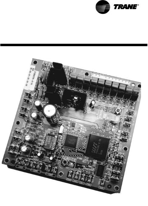
The Trane® Tracer® ZN.520 controller is a factory-installed and
commissioned, direct-digital controller (DDC) offering for classroom unit ventilator sys-
tems. (See Figure 1: “Tracer ZN.520 Control Board”) The Tracer ZN.520 can also be applied to
other Trane® interoperable HVAC equipment, including the fan coil and blower coil products. (For
more information see,Table 1: Tracer™ ZN.520 Unit Controller features and coil availability, on
page 8 for more information.) For more information regarding the application of the Tracer ZN.520
to other Trane products, contact the appropriate local Trane sales office.
Trane offers a complete solution to space comfort control with the
flexibility of Integrated Comfort System (ICS) and stand-alone control packages. The ICS control
package combines HVAC equipment and building management into one environmental comfort
system.
Integrating the Tracer ZN.520 on
classroom unit ventilators, and tying them to a Tracer Summit® system will provide a complete
building management system. The stand-alone control package offers the features and function-
ality of the direct digital control without a front-end building automation system, while providing
future considerations for ICS.
Equipment problems can often be
diagnosed on each unit without having to access the unit componets. These diagnostics can be re-
ceived remotely via a modem with a Tracer Summit building automation system, thus reducing the
number of actual on-site service calls; through the Rover® service tool connected to a communica-
tion jack located inside the Trace zone sensor; or connected to the unit.
Figure 1: Tracer ZN.520 Control Board
The Tracer ZN.520 is factorymounted, tested, wired, config-
ured and commissioned for the selected application.
The Tracer ZN.520 configuration has flexible point and product configurations. For example, with
point configuration, a specific binary point can be configured to accept input from either a time clock
or some type of generic device.
UV-SVP01A-EN |
7 |
General Information
Table 1: Tracer™ ZN.520 Unit Controller features and coil availability |
|
|
|
|
|||||
|
|
|
Auto |
Face and |
|
|
|
Entering |
|
|
Multiple |
Dehumid- |
Valve |
Economizer |
Auxiliary |
Water |
|||
Coil |
Damper |
Bypass |
|||||||
Fan Speeds |
ification |
Control |
Damper |
Heat2 |
Temperature |
||||
|
Adjust |
Damper |
|||||||
|
|
|
|
|
|
Sampling |
|||
|
|
|
|
|
|
|
|
||
2-pipe changeover |
X |
|
X |
X |
X |
X |
X |
X |
|
2-pipe hot water |
X |
|
X |
X |
X |
X |
X |
|
|
only |
|
|
|||||||
|
|
|
|
|
|
|
|
||
2-pipe steam only |
X |
|
X |
X |
|
X |
X |
|
|
2-pipe changeover/ |
X |
X |
X |
|
X |
X |
X |
X |
|
electric heat |
|
||||||||
|
|
|
|
|
|
|
|
||
2-pipe cool only |
X |
|
X |
|
X |
X |
|
|
|
2-pipe cool only/ |
X1 |
|
X1 |
|
X |
X |
X |
|
|
electric heat |
|
|
|
||||||
|
|
|
|
|
|
|
|
||
4-pipe hot water/ |
X |
X |
X |
X3 |
X |
X |
X |
|
|
chilled water |
|
||||||||
|
|
|
|
|
|
|
|
||
4-pipe changeover |
X |
X |
X |
X3 |
X |
X |
X |
X |
|
4-pipe steam/chilled |
X |
|
X |
|
X |
X |
X |
|
|
water |
|
|
|
||||||
|
|
|
|
|
|
|
|
||
Electric heat only |
|
|
|
|
|
X |
X |
|
|
DX/hot water |
X1 |
|
X1 |
|
X |
X |
X |
|
|
DX/steam |
X1 |
|
X1 |
|
X |
X |
X |
|
|
DX/electric heat |
|
|
|
|
|
X |
X |
|
|
DX cooling only |
|
|
|
|
|
X |
|
|
|
1.Multiple fan speeds are available in hydronic units only.
2.Auxiliary heat is designed to bring on baseboard heat as the second stage of heating. The baseboard heat must be the same type as the
unit heating coil.
3. Units with face bypass dampers cannot actively dehumidify.
8 |
UV-SVP01A-EN |

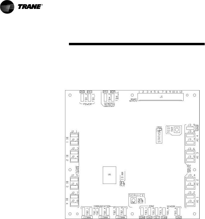
Controller Circuit Board
Features
Power
Generic
Auto Test Button
Status LED
Communications LED
Service Button and LED
Communications |
Zone Sensor Connections |
|
Figure 2: Tracer ZN.520 unit controller circuit board
UV-SVP01A-EN |
9 |
Controller Features
Each Tracer ZN.520 unit controller circuit board is equipped with enhancements to help facilitate ser-
vice, testing, and diagnosis. Each board has
qManual test button,
qStatus LED,
qCommunication status LED,
qService button,
qQuick terminal connectors, and
qEasy to read screen printing.
(See Figure 1: “Tracer ZN.520 Control Board”).
Service
The Trane Tracer ZN.520 unit con-
troller is serviced using Rover®, the ICS software service too. Rover is designed to support the Tracer
ZN.520 unit controller on the classroom unit ventilator.
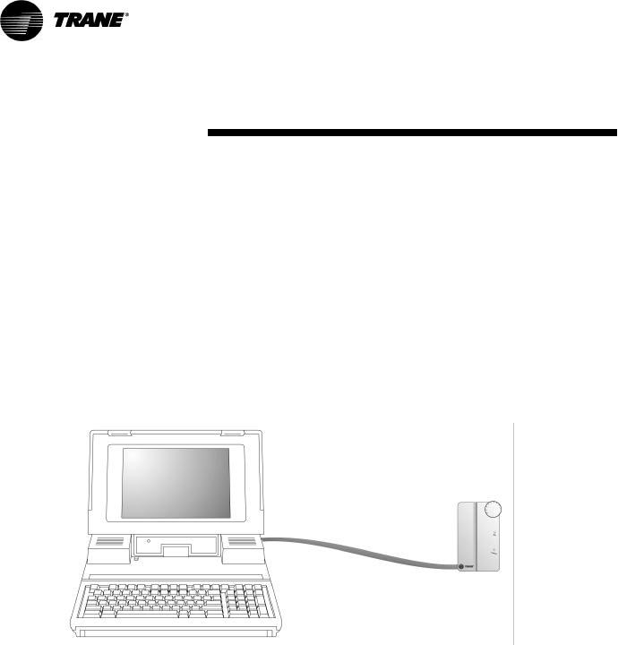
For “remote” access to the communicating units, the zone sensors offered with the Tracer ZN.520
have a telephone style (RJ-11) connector allowing field connection between Rover and the zone sen-
sor; however, the RJ-11 connector must be connected to the terminals TB2-5 and TB2-6 on the Tracer
ZN.520 unit controller.(See Figure 3: “Rover service tool connected to the RJ-11 communication jack in a
zone sensor”)
The zone sensor may also be used when trying to locate a unit. By pressing the ON button on the zone
sensor for 5 seconds or using the “wink” command in Rover, the circuit board receives the signal caus-
ing the Communication LED to “wink”. Winking allows visual identifier on the board for service
technicians.
The Tracer ZN.520 also includes
features such as a test output to manually test all of the end devices and color coded wires (i.e. red for
heating valves and blue for cooling valves) to aid in the troubleshooting process.(See “Manual Output
Test” on page 48, for more information.)
Figure 3: Rover service tool connected to the RJ-11 communication jack in a zone sensor
Typical Components
A typical classroom unit ventilator
system with a DDC package consists of the following physical components, in addition to the
mechanical equipment:
qTracer ZN.520—contains the
sensor input circuits, service adjustments, microprocessor control electronics, and communications hardware.
Power is supplied by a separately mounted 24 VAC\90 VA transformer.
qSensor Modules—a variety of analog sensors that provide
temperature and optional
humidity sensing and CO2 sensor; and an operator interface to the Tracer ZN.520 for operating modes, status, and temperature setpoints.
qStandard End Devices—a variety of devices that help to gather information, control
capacity, and provide ventilation are used by the Tracer ZN.520 in its control
algorithm to condition the space to the desired temperature and relative
humidity level. (See “Standard End Devices” on page13, for more information.)
10 |
UV-SVP01A-EN |
Communication Configurations
Note: The Tracer ZN.520 is a |
connect to a maximum of 120 |
configured controller. It will |
Tracer ZN.520 controllers. |
not operate without a valid |
|
downloaded configuration |
|
file. |
|
The Tracer ZN.520 controller sup- |
|
ports ICS and peer-to-peer com- |
|
munications as well as stand- |
|
alone operation. A number of con- |
|
trol features may be configured at |
|
the factory or by using the Rover |
|
service tool. (See “Configuration” |
|
on page32, for more information.) |
|
Integrated Comfort
System
Note: The Tracer ZN.520
controller may only be used with Tracer Summit version 11.0 or greater with a Comm5
communications card.
Classroom unit ventilators can op-
erate as part of a large building automation system controlled by Tracer Summit. The Tracer ZN.520
is linked directly to the Tracer Summit via a twisted pair communication wire. Each Tracer Summit
building automation system can
Figure 4: Communications link wire
The ICS system allows for complete communication with the classroom unit ventilators via
Tracer ZN.520 unit controller. All points connected to the Tracer ZN.520 may be observed from the
Tracer Summit front-end controller. The Tracer Summit can also initiate an alarm on a loss of per-
formance or equipment malfunctions.
The ICS system also allows all of
the classroom unit ventilators to share information without the presence of hardwired sensors at
each unit. Some typical shared points include outside air temperature, entering water temperature,
and occupancy schedules.
Peer-to-Peer
Communications
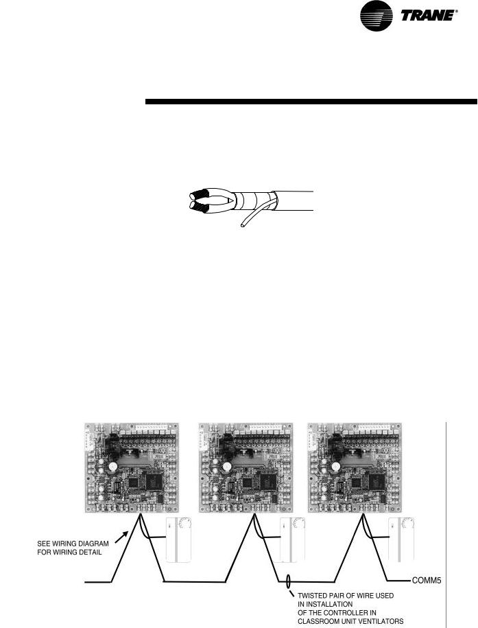
On a peer-to-peer communication
system, multiple Tracer ZN.520 controllers may share data, via a twisted pair communication wire,
without the need for a Tracer Summit system. (See Figure 5: “Peer- to-peer communication connec-
tions”)
Peer-to-peer communications al-
lows features such as master/slave operation, in which multiple units operate off of a single zone sensor.
This is typically seen in large spaces requiring multiple units.
The Rover service tool is required to set up peer-to-peer communications.
Figure 5: Peer-to-peer communication connections
UV-SVP01A-EN |
11 |
Communication Configurations
Stand-Alone
In a stand-alone configuration,
commands for operation are determined based on input from the zone sensor, humidity sensor, and
factoryor field-mounted timeclock.(See Figure 6: “Typical classroom unit ventilator installation”)
qThe timeclock is wired to the Tracer ZN.520 to index the unit
between occupied and unoccupied modes.
qA unit-mounted, analog, outside-air temperature sensor is used to initiate the dry bulb
economizer and freeze avoidance routines.
qOn changeover units, a unitmounted, analog, entering water temperature sensor is
used to automatically control the system in the heat/cool mode.
These sensors are required for proper system operation and are
provided as standard on standalone units.
Figure 6: Typical classroom unit ventilator installation
Communication Interface
Important! To help ensure
optimal performance of the Rover service tool, please use the latest version. To obtain
the latest version contact your local Trane sales representtative or service technician.
Note: Refer to the Tracer system manuals for more
information on communications.
The Tracer ZN.520 communicates via Comm5 (LonTalk) to a building management system, the Rover
service tool, and other unit controllers on the communications link. Each Tracer ZN.520 requires a
unique address for the system to operate properly. Every Tracer ZN.520 has this address (Neuron
ID) embedded in the microprocessor, which eliminates the need for field-addressing of the units. Each
unit also ships from the factory with a unit identification tag. (See “Location Identifier” on page38,
for more information.)
Building automation system
Trane offers a state-of the art frontend building automation system designed to coordinate and moni-
tor Trane equipment and controllers: Tracer Summit.
The Tracer Summit system allows the user to monitor and/or change Tracer ZN.520:
qstatus, parameters, sensor data, diagnostics, and internal variables; and
qsetpoints, operating modes, and outputs.
Service tool
Trane also offers a service tool to work in conjunction with the Tracer Summit system or with peer-to-
peer and stand-alone systems: the Rover service tool.
Communication to the Tracer ZN.520, or multiple controllers, can also be accomplished by using the
ICS software service tool.
A personal computer running Rover may be directly connected to a standalone Tracer ZN.520; con-
nected to the communications jack in the Trane zone sensor; or connected to a communicating unit’s
Tracer ZN.520 unit controller, to access all of the units on a communicating link.
Rover allows the user to interface with the Tracer ZN.520, but will not
allow any advanced control (e.g. equipment scheduling or trending). To purchase a copy of the ICS
software service tool, contact the BAS department at your local Trane dealer.
Interoperability
Trane has lead the industry with BACnet interoperability and Trane
is now expanding the realm of interoperable solutions by offering LonMark certified unit controllers.
The Tracer ZN.520 controller conforms to the LonMark Space Comfort Controller profile. (See
“Appendix—Data Lists” on page64, for more information.)
This allows the ZN.520 to be used
as a unit controller on other control systems that support LonTalk and the SCC profile. Now building own-
ers have more choices and design engineers have more flexibility to meet the challenges of building au-
tomation.
12 |
UV-SVP01A-EN |
Standard End Devices
Table 2: End Device Specifications
Device
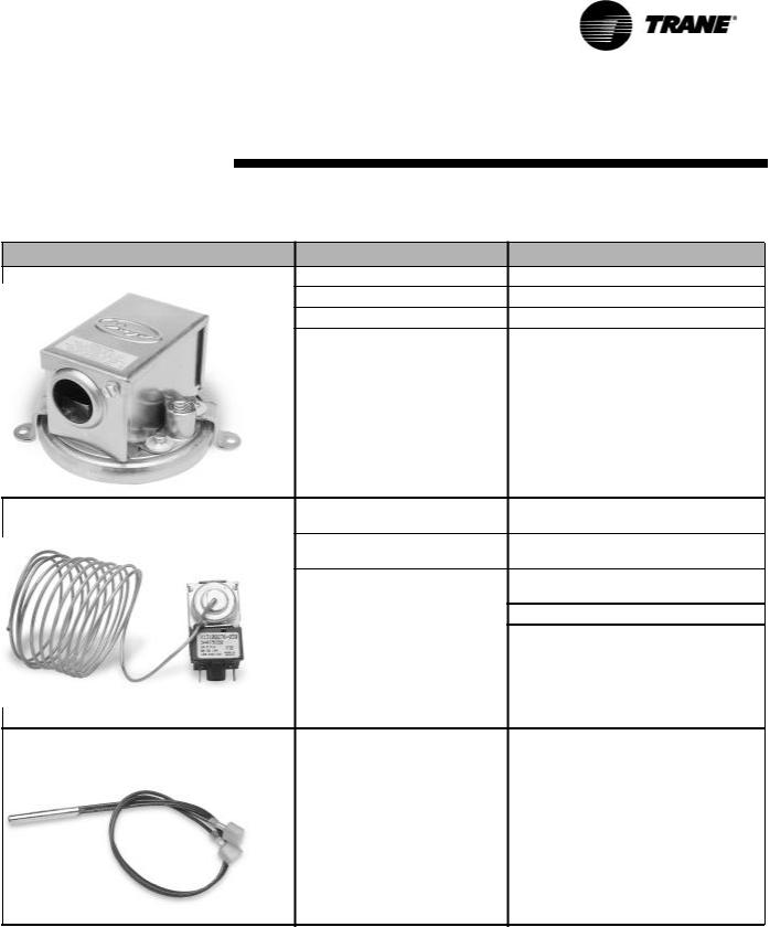
Fan Status Switch
Low Temperature Detection Switch (Freezestat)
OutsideAir Sensor/discharge AirSensor/Entering
Water Temperature Sensor/Unit Mounted, Zone
Return-air Temperature Sensor
Characteristic
Material
Operating Temperature Range
Contact Form
Preset
Trip Temperature:
Release Temperature
Rating—Auto Reset
Sensing Element
Description
Contact Blade—Pilot duty rated
-40°F/250°F (-40°C/120°C)
SPST-NO
Fan status - 0.07”
36°F ± 2°F (2°C + - 1.11°C)
44°F ± 3°F (6.67°C + - 1.67°C)
Pilot Duty |
120 |
VAC |
240 |
VAC |
|
(24 VAC) |
|||||
|
|
|
|
||
FLA |
10.0 |
|
5.0 |
|
|
LRA |
60.0 |
|
30.0 |
|
|
|
|
|
|
|
Thermistor 10 KOhms @ 77°F ± 1.8°F (25°C ±1°C)
UV-SVP01A-EN |
13 |
Standard End Devices
Table 2: End Device Specifications |
|
|
|
|
|
Device |
Characteristic |
Description |
|
|
|
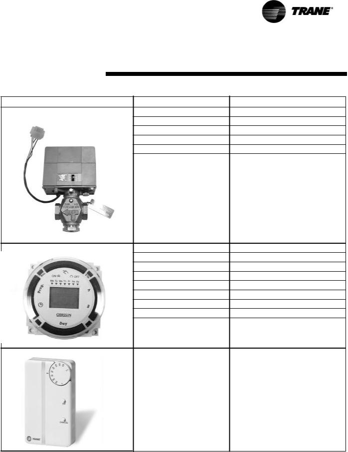
Outside Air Actuator |
Description |
Three-point floating with spring return |
|
Ambient Temperature Rating |
-25°F to 125°F |
|
Power Consumption |
5 VA |
|
Torque |
35 in-lbs. |
Drive Time |
90 seconds, 95 degree stroke |
Face and Bypass Actuator |
Description |
Three-point floating |
|
Ambient Temperature Rating |
32°F to 122°F |
|
Power Consumption |
3 VA |
|
Torque |
35 in-lbs. |
Drive Time |
80-110 seconds, 95 degree stroke |
2-way Control Valve |
Description |
Three-point modulating |
|
Ambient Temperature Rating |
140°F at 95% relative humidity |
|
Drive Time |
50 seconds |
|
Max Pressure |
400 psi water |
|
Close Off |
Varied by size and Cv |
Temperature |
Water 200°F maximum |
14 |
UV-SVP01A-EN |
Standard End Devices
Table 2: End Device Specifications |
|
|
|
|
|
Device |
Characteristic |
Description |
|
|
|
3-way Control Valve |
Description |
Three-point modulating |
|
Ambient Temperature Rating |
140°F at 95% relative humidity |
|
Drive Time |
50 seconds |
|
Max Pressure |
400 psi water |
|
Close Off |
Varied by size and Cv |
Temperature |
Water 200°F maximum |
Time clock |
Size |
2.83'' x 4.0'' x 2.06'' |
|
Power Consumption |
4.4 VA |
|
Switch |
SPDT dry contacts, silver cadmium oxide |
|
Switch Rating |
16A 250V resistive, 1000 Watts tungsten |
|
Minimum Switching Current |
100mA,230V |
|
Shortest Switching Time |
1 minute |
|
Ambient Temperature Range |
-14°F to 131°F |
|
Wiring Connections |
Screw terminals suitable for #10 to #24 AWG |
|
Backup |
Seven day capacitor backup |
|
|
|
Zone sensor |
|
|
Zone Sensor Wiring Size And |
16-22 AWG: up to 200 feet |
|
Maximum Lengths |
||
|
UV-SVP01A-EN |
15 |
Standard End Devices
Table 2: End Device Specifications |
|
|
|
|
|
|
|
Device |
Characteristic |
Description |
|
|
|
|
|
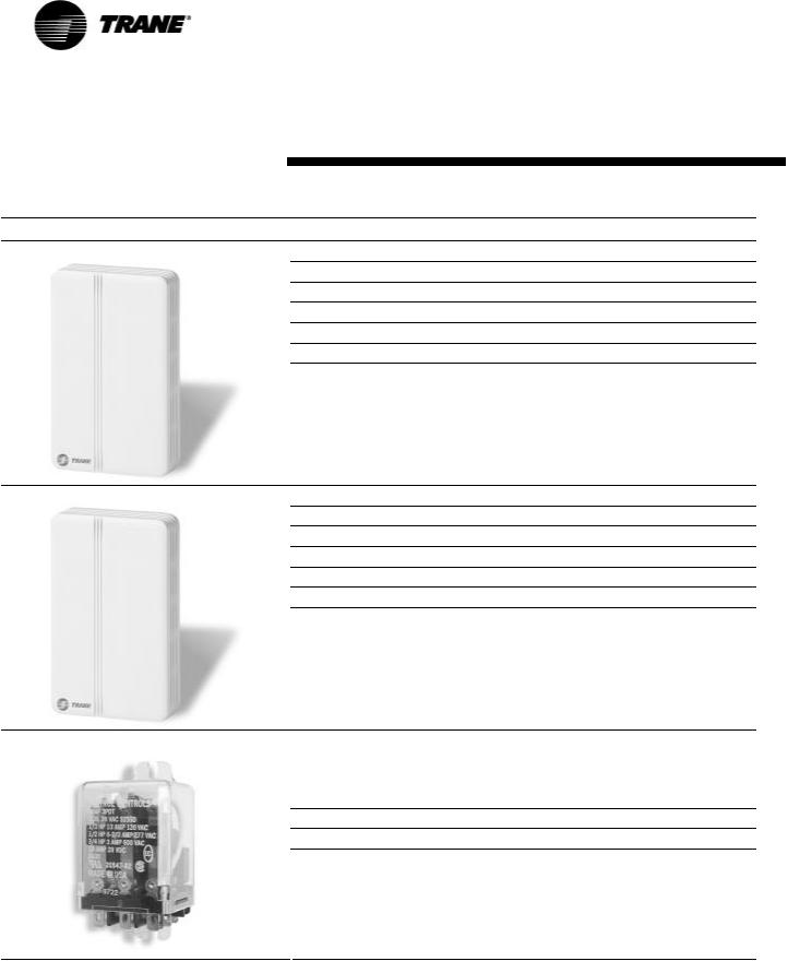
Humidity Sensor |
Sensing Element |
Polymer capacitive |
|
|
Sensing Element |
Accuracy: ± 5% over 20-95% RH @ 77ºF |
|
|
Range |
0 to 99% RH |
|
|
Operating Temperature Range |
0°F to 140ºF |
|
|
Max Supply Voltage |
24VDC |
|
|
Output Characteristics |
4 to 20 MA for 0-100% RH |
|
|
Drift Rate |
Less than 1% per year |
|
CO 2 Sensor |
Sensing Element |
Accuracy: ± 100ppm full scale |
|
|
Range |
0-2000 ppm |
|
|
Operating Temperature Range |
59°F to 95ºF |
|
|
Supply Voltage |
24VAC |
|
|
Output Characteristics |
0-10 VDC for 0-2000 ppm |
|
|
Power consumption |
10 VA |
|
|
Drift Rate |
±5% full scale over four years |
|
Fan Relay |
|
20 amps at 120/240 vac |
|
|
|
||
|
|
3/4 hp at 120 vac |
|
|
Contact Rating |
1 1/2 hp at 240 vac |
|
|
|
20 amps @ 28 vdc |
|
|
|
DPDT |
|
|
Terminals |
0.25 quick connect |
|
|
Contact material |
Silver-Cadium Oxide |
|
|
Coil |
24 vac 2.7 va |
|
|
|
|
|
16 |
UV-SVP01A-EN |
Standard End Devices
Table 2: End Device Specifications |
|
|
|
|
|
Device |
Characteristic |
Description |
|
|
|
|
Type |
N.E.C. Class 2 |
|
Primary Voltage |
120 vac |
Control Transformer |
|
24 vac at 90 va |
|
|
|
|
Secondary voltage |
Manual reset |
|
|
4amp fuse in 24-volt circuit |
|
|
|
UV-SVP01A-EN |
17 |
Installation and Wiring
Specifications
Dimensions
Tracer ZN.520 board and mounting hardware:
•Height: 5.25 inches (133 mm.)
•Width: 5.50 inches (140 mm)
•Depth: 2.25 inches (57 mm)
Power Requirements
•18 to 32 VAC (24 VAC nominal)
•50 or 60 Hz
•570 mA AC
Operating Environment
•32° to 140°F (0× to 60°C)
•5% to 95% relative humidity, non-condensing
Storage Environment
•-40° to 185°F (-40° to 85°C)
•5% to 95% relative humidity, non-condensing
Agency Listings
•UL and CUL 916 Energy Management System
•Agency Compliance IEC 1000- 4-2 (ESD), IEC 1000-4-4(EFT), IEC 1000-4-5 (Surge)
Figure 7: Tracer ZN.520 circuit board schematic
18 |
UV-SVP01A-EN |

Installation and Wiring
Binary Inputs
Each binary input associates an input signal of 0 VAC with open con-
tacts and 24 VAC with closed contacts.
Table 3: Binary inputs (typically 24 mA AC)
Description |
Terminals |
Terminal Function |
|
Binary input 1 |
J2-1 |
24 VAC |
|
(BI 1) |
|||
|
|
||
|
J2-2 |
Input |
|
Binary input 2 |
J2-3 |
24 VAC |
|
(BI 2) |
|||
|
|
||
|
J2-4 |
Input |
|
Binary input 3 |
J2-5 |
24 VAC |
|
(BI 3) |
|||
|
|
||
|
J2-6 |
Input |
|
Binary input 4 |
J2-7 |
24 VAC |
|
(BI 4) |
|||
|
|
||
|
J2-8 |
Input |
UV-SVP01A-EN |
19 |

Installation and Wiring
Binary Outputs
Outputs are load side switching tri-
acs. The triac acts as a switch, either making or breaking the circuit between the load (valve, damper,
contactor, relay) and ground.
Table 4: Binary outputs
Description
Fan high
Fan medium,
Exhaust fan
Fan low
No connection
Cool open, face bypass cool valve DX, 2-position cooling valve, BI 5
Cool close
Face/bypass damper open
Face/bypass damper close
Heat open
Face bypass isolation valve, 2-position heating valve Electric heat 1st stage
Heat close
Electric heat 2nd stage
Economizer damper open
Economizer damper close
Terminals |
Output |
|
Rating |
||
|
||
J1-1 |
12 VA |
|
J1-2 |
12 VA |
|
J1-3 |
12 VA |
|
J1-4 (Key) |
— |
|
J1-5 |
12 VA |
|
J1-6 |
12 VA |
|
J1-7 |
12 VA |
|
J1-8 |
12 VA |
|
J1-9 |
12 VA |
|
J1-10 |
12 VA |
|
J1-11 |
12 VA |
|
J1-12 |
12 VA |
Load Energized |
Load De-energized |
1 VAC RMS |
24 VAC RMS |
(typical) |
(typical) |
1 VAC RMS |
24 VAC RMS |
(typical) |
(typical) |
1 VAC RMS |
24 VAC RMS |
(typical) |
(typical) |
— |
— |
1 VAC RMS |
24 VAC RMS |
(typical) |
(typical) |
1 VAC RMS |
24 VAC RMS |
(typical) |
(typical) |
1 VAC RMS |
24 VAC RMS |
(typical) |
(typical) |
1 VAC RMS |
24 VAC RMS |
(typical) |
(typical) |
1 VAC RMS |
24 VAC RMS |
(typical) |
(typical) |
1 VAC RMS |
24 VAC RMS |
(typical) |
(typical) |
1 VAC RMS |
24 VAC RMS |
(typical) |
(typical) |
1 VAC RMS |
24 VAC RMS |
(typical) |
(typical) |
Generic/baseboard Heat Binary Output
Table 5: Generic binary outputs |
|
|
|
|
Description |
Terminals |
Output |
Load Energized |
Load De-energized |
|
|
Rating |
|
|
Generic/ baseboard heat output |
TB4-1 |
12 VA |
1 VAC RMS |
24 VAC RMS |
|
|
|
(typical) |
(typical) |
24VAC |
TB4-2 |
12 VA |
NA |
NA |
20 |
UV-SVP01A-EN |
Installation and Wiring
Analog Inputs
Table 6: Analog inputs |
|
|
|
Description |
Terminals |
Function |
Range |
Zone |
TB3-1 |
Space temperature input |
5° to 122°F |
|
|
|
(-15° to 50°C) |
Ground |
TB3-2 |
Analog ground |
NA |
Set |
TB3-3 |
Setpoint input |
40 ° to 115 °F |
|
|
|
(4.4° to 46.1°C) |
Fan |
TB3-4 |
Fan switch input |
4821 to 4919 Ω (Off) |
|
|
|
2297 to 2342 Ω (Auto) |
|
|
|
10593 to 10807 Ω (Low) |
|
|
|
13177 to 13443 Ω (Medium) |
|
|
|
15137 to 16463 Ω (High) |
Ground |
TB3-6 |
Analog ground |
NA |
Analog Input 1 |
J3-1 |
Entering water temperature |
-40° to 212°F (-40° to 100° C) |
|
J3-2 |
Analog ground |
NA |
Analog Input 2 |
J3-3 |
Discharge air temperature |
-40° to 212°F (-40° to 100° C) |
|
J3-4 |
Analog ground |
NA |
Analog Input 3 |
J3-5 |
Outdoor air temperature / Generic |
-40° to 212°F (-40° to 100° C) |
|
|
temperature |
|
|
J3-6 |
Analog ground |
NA |
Analog Input 4 |
J3-7 |
Power port |
4-20 mA |
|
J3-8 |
Universal input |
|
|
|
Generic 4-20ma |
0 – 100% |
|
|
Humidity |
0 – 100% |
|
|
CO2 |
0 – 2000ppm |
|
J3-9 |
Analog ground |
NA |
UV-SVP01A-EN |
21 |
Installation and Wiring
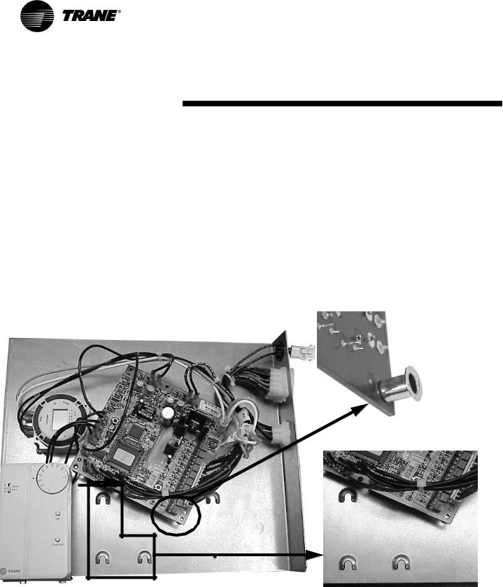
Mounting
The Tracer ZN.520 circuit board is
mounted in the left-hand end pocket for all classroom unit ventilator configurations. The sheet metal
mounting plate has raised embosses to accept the mounting feet on the circuit board. (See Figure 8:
“Classroom unit ventilator control box with close-up of horseshoe embosses and circuit board
mounting feet.”) This design allows the Tracer ZN.520 controller to be secured with a minimal num-
ber of sheet metal screws.
Figure 8: Classroom unit ventilator control box with close-up of horseshoe embosses and circuit board mounting feet.
22 |
UV-SVP01A-EN |
Installation and Wiring
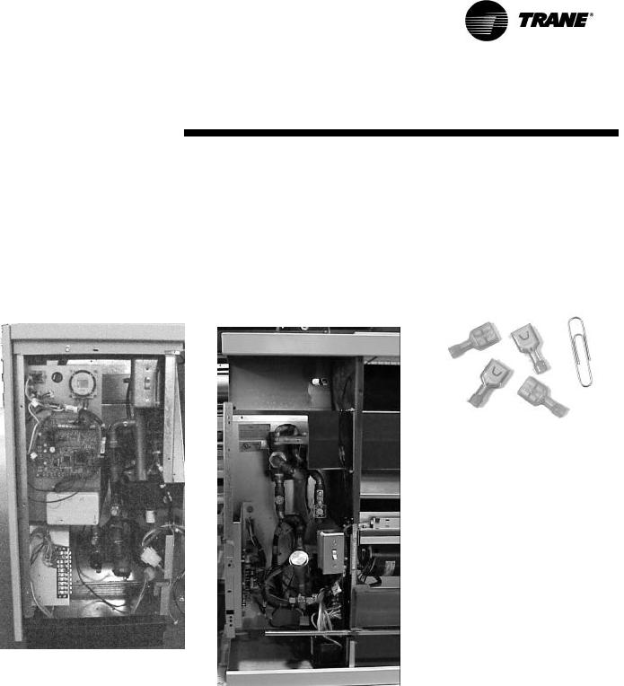
The mounting position on the ver-
tical classroom unit ventilator configuration allows complete access to the Tracer ZN.520 by re-
moving the front panel. (See Figure 9: “Vertical classroom unit ventilator end pocket”) The
mounting plate swings out of the way with the removal of a single screw to allow access to the com-
ponents behind the control board.
The mounting plate on the hori-
zontal classroom unit ventilator configuration is designed to slide out with the removal of a sin-
gle screw for complete access to the Tracer ZN.520. (See Figure 10: “Horizontal classroom unit venti-
lator end pocket”) The location of the control board on this unit configuration allows complete access
to the other components in the end pocket when the front panel is removed.
For additional convenience, quick
connects and modular wire harnesses are used on the control board and mounting plate. (See
Figure 11: “Quick connects to control board in the classroom unit ventilator”) These quick connects
help facilitate ease of wiring devices (e.g., zone sensor) to the control board, and helps add accessibility
to major components.
Figure 11: Quick connects to control board in the classroom unit ventilator
Figure 9: Vertical classroom unit ventilator end pocket
Figure 10: Horizontal classroom unit ventilator end pocket
UV-SVP01A-EN |
23 |
Installation and Wiring
Wiring
! WARNING
Warning! Disconnect all electrical power before servicing unit to prevent injury or death due to electrical shock. Use copper conductors only. The use of aluminum or other incorrect types of wire may result in overheating and equipment damage.
! CAUTION
Caution: To prevent damage to the unit ventilator, refer to the diagram provided on the inside of the unit's access panel for specific wiring infor-
mation. All controls are wired at the factory. Single point power, zone sensor, and communication wiring is to be installed by the contractor.
Important! All wiring must comply with state, local, and federal guidelines. Contact the
appropriate local agency for furthur information.
Important! Wires for temperature sensors, communication lines, 24 VAC,
and contact closure sensing inputs should not be bundled with or run near high voltage
wiring.
qPower wiring must be
separated from the Tracer ZN.520 and all low voltage wires. External input wires
should be run in separate conduits from high voltage wires.
qWires connected to pin headers should be formed and routed
so as to cause minimum strain on the Tracer ZN.520 connector.
qA minimum of 1.5" clearance (from the pin centerline) for wires up to 16 AWG is
recommended for bending and forming wires.
qAll sensor and input circuits are at or near ground potential. Do not connect any sensor or input
circuit to an external ground connection.
qA close-coupled ground connection is required for the Tracer ZN.520. T
qTable 7: Tracer ZN.520 Wiring Requirements, shows Tracer ZN.520 wire types and lengths.
Table 7: Tracer ZN.520 Wiring
Requirements
Application |
Wire Type |
Length |
|
|
|
|
|
Contact Closure |
18 AWG |
Up to |
|
1000 ft. |
|||
|
|
||
24 VAC |
16-22 AWG |
Up to |
|
1000 ft. |
|||
|
|
||
Thermostat |
16-22 AWG |
Up to |
|
1000 ft. |
|||
|
|
||
Zone |
16-22 AWG |
Up to |
|
Sensor |
200 ft. |
||
|
|||
Communications |
Belden 8760 |
Up to |
|
|
or equivalent |
5000 ft. |
Power
The Tracer ZN.520 controller is
powered by 24 VAC. (See Table 7: “Tracer ZN.520 Wiring Requirements”)A total of two 1/4-inch
quick-connect terminals are provided for 24 VAC connection to the board.
Figure 12: Power connection to the Tracer ZN.520 unit controller
24 |
UV-SVP01A-EN |
Installation and Wiring
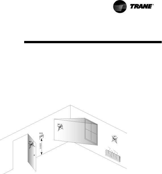
Installing the WallMounted Zone Sensor (Optional)
Zone sensor location is an important element of effective room
control and comfort.
The best sensor location is typical-
ly on a wall, remote from the HVAC unit. Readings at this location assure that the desired set-
point is achieved across the space, not just near the unit itself.
Note: It may be necessary to
subdivide the zone with multiple units to ensure adequate control and comfort
throughout the space.
The following are typical areas
where the zone sensor should NOT be mounted:
qNear drafts or “dead spots” (e.g., behind doors or corners);
qNear hot or cold air ducts;
qNear radiant heat (e.g., heat
emitted from appliances or the sun);
qNear concealed pipes or chimneys;
qOn outside walls or other nonconditioned surfaces; or
qIn air flows from adjacent zones or other units.
Figure 13: Proper zone sensor placement
Note: All zone sensor wiring
will be done in the factory unless zone sensor options are selected to be wall mounted.
When a unit-mounted speed switch is selected with a wall-
mounted zone sensor, the contractor must disconnect the cooling setpoint on the unit mounted sen-
sor if the wall mounted cooling setpoint is used. The zone signal will be cut at the factory. The unit-
mounted speed switch cannot be used as a zone sensor.
THe communications link is not connected in the factory. Communications should be wired to the
wall-mounted sensor.
UV-SVP01A-EN |
25 |
Installation and Wiring
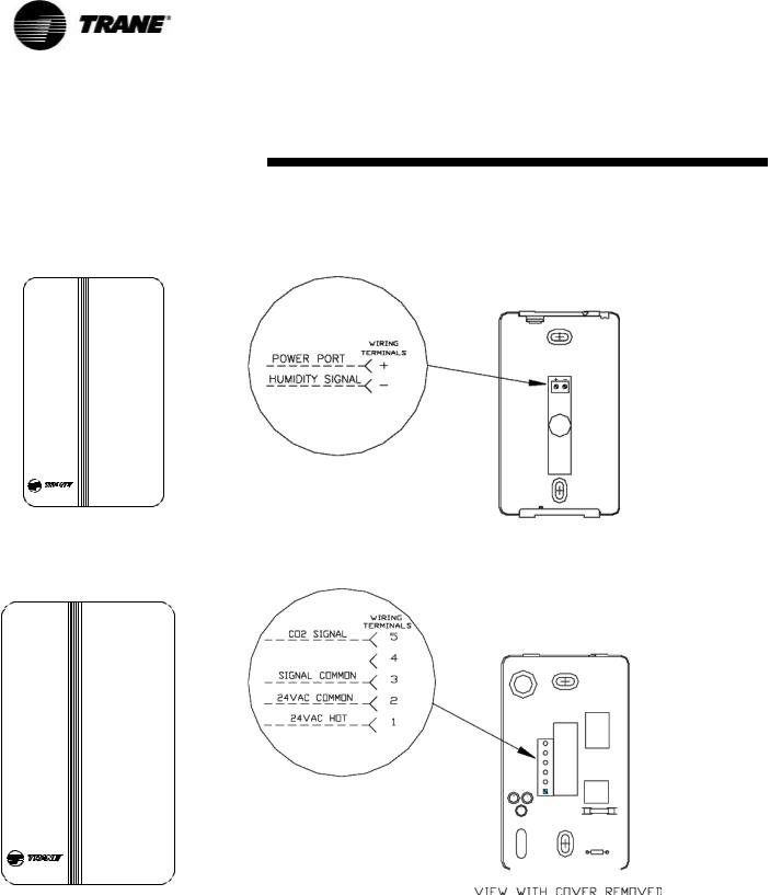
Humidity and CO2 Sensors
Humidity and CO2 sensors should be mounted in a similar location as the zone sensor.
Figure 14: Relative humidity sensor
Figure 15: CO 2 Sensor
26 |
UV-SVP01A-EN |
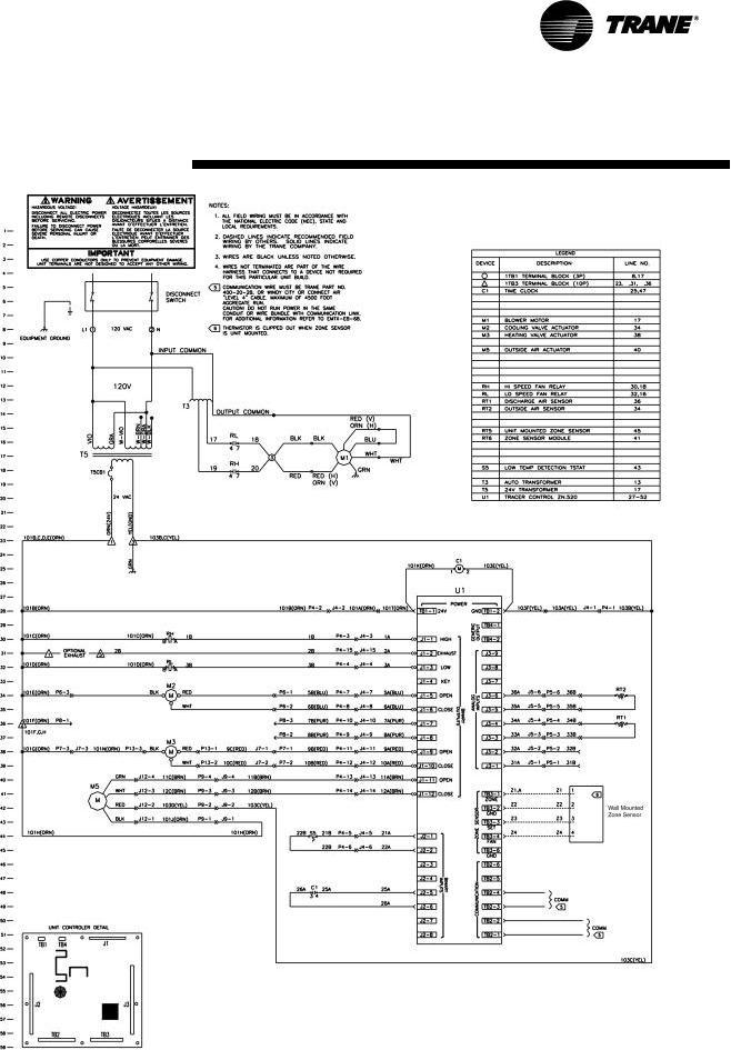
Typical Wiring Diagram—Wall
Mounted Zone Sensor
UV-SVP01A-EN |
27 |
 Loading...