


COMPACT PLAYER
J-10
J-10SDI
J-30
J-30SDI

 (J-30/30SDI)


 (J-30/30SDI)
OPERATION MANUAL [English] 1st Edition

WARNING
To prevent fire or shock hazard, do not expose the unit to rain or moisture.
To avoid electrical shock, do not open the cabinet. Refer servicing to qualified personnel only.
WARNING
THIS APPARATUS MUST BE EARTHED.
This symbol is intended to alert the user to the presence of uninsulated “dangerous voltage” within the product’s enclosure that may be of sufficient magnitude to constitute a risk of electric shock to persons.
This symbol is intended to alert the user to the presence of important operating and maintenance (servicing) instructions in the literature accompanying the appliance.
Important Safety Instructions
•Read these instructions.
•Keep these instructions.
•Heed all warnings.
•Follow all instructions.
•Do not use this apparatus near water.
•Clean only with dry cloth.
•Do not block any ventilation openings. Install in accordance with the manufacturer’s instructions.
•Do not install near any heat sources such as radiators, heat registers, stoves, or other apparatus (including amplifiers) that produce heat.
•Do not defeat the safety purpose of the polarized or grounding-type plug. A polarized plug has two blades with one wider than the other. A grounding type plug has two blades and a third grounding prong. The wide blade or the third prong are provided for your safety. If the provided plug does not fit into your outlet, consult an electrician for replacement of the obsolete outlet.
•Protect the power cord from being walked on or pinched particularly at plugs, convenience receptacles, and the point where they exit from the apparatus.
•Only use attachments/accessories specified by the manufacturer.
•Use only with the cart, stand, tripod, bracket, or
table specified by the manufacturer, or sold with
the apparatus. When a cart is used, use caution
when moving the cart/apparatus combination to
avoid injury from tip-over.
•Unplug this apparatus during lightning storms or when unused for long periods of time.
•Refer all servicing to qualified service personnel. Servicing is required when the apparatus has been damaged in any way, such as power-supply cord or plug is damaged, liquid has been spilled or objects have fallen into the apparatus, the apparatus has been exposed to rain or moisture, does not operate normally, or has been dropped.
WARNING: THIS WARNING IS APPLICABLE FOR USA ONLY.
If used in USA, use the UL LISTED power cord specified below.
DO NOT USE ANY OTHER POWER CORD.
Plug Cap |
Parallel blade with ground pin (NEMA 5-15P |
|
Configuration) |
Cord |
Type SJT, three 16 or 18 AWG wires |
Length |
Minimum 1.5m |
Rating |
Minimum 10A, 125V |
Using this unit at a voltage other than 120V may require the use of a different line cord or attachment plug, or both.
To reduce the risk of fire or electric shock, refer servicing to qualified service personnel.
WARNING: THIS WARNING IS APPLICABLE FOR OTHER COUNTRIES.
1.Use the approved Power Cord (3-core mains lead) / Appliance Connector / Plug with earthing-contacts that conforms to the safety regulations of each country if applicable.
2.Use the Power Cord (3-core mains lead) / Appliance Connector / Plug conforming to the proper ratings (Voltage, Ampere).
If you have questions on the use of the above Power Cord / Appliance Connector / Plug, please consult a qualified service personnel.

CAUTION
Danger of explosion if battery is incorrectly replaced.
Replace only with the same or equivalent type recommended
by the manufacturer. Dispose of used batteries according to
the manufacturer’s instructions.
CAUTION
The apparatus shall not be exposed to dripping or splashing
and no objects filled with liquid, such as vases, shall be
placed on the apparatus.
Do not install the appliance in a confined space, such as
book case or built-in cabinet.
CAUTION
The unit is not disconnected from the AC power source
(mains) as long as it is connected to the wall outlet, even if
the unit itself has been turned off.
For the customers in the USA
This equipment has been tested and found to comply with the limits for a Class A digital device, pursuant to Part 15 of the FCC Rules. These limits are designed to provide reasonable protection against harmful interference when the equipment is operated in a commercial environment. This equipment generates, uses, and can radiate radio frequency energy and, if not installed and used in accordance with the instruction manual, may cause harmful interference to radio communications. Operation of this equipment in a residential area is likely to cause harmful interference in which case the user will be required to correct the interference at his own expense.
You are cautioned that any changes or modifications not expressly approved in this manual could void your authority to operate this equipment.
The shielded interface cable recommended in this manual must be used with this equipment in order to comply with the limits for a digital device pursuant to Subpart B of Part 15 of FCC Rules.
For the customers in Europe
This product with the CE marking complies with both the EMC Directive (89/336/EEC) and the Low Voltage Directive (73/23/EEC) issued by the Commission of the European Community.
Compliance with these directives implies conformity to the following European standards:
•EN60065: Product Safety
•EN55103-1: Electromagnetic Interference (Emission)
•EN55103-2: Electromagnetic Susceptibility (Immunity) This product is intended for use in the following Electromagnetic Environment(s):
E1 (residential), E2 (commercial and light industrial), E3 (urban outdoors) and E4 (controlled EMC environment, ex. TV studio).
AVERTISSEMENT
Afin d’éviter tout risque d’incendie ou d’électrocution, ne pas exposer cet appareil à la pluie ou à l’humidité.
Afin d’écarter tout risque d’électrocution, garder le coffret fermé. Ne confier l’entretien de l’appareil qu’à un personnel qualifié.
AVERTISSEMENT
CET APPAREIL DOIT ETRE MIS A LA TERRE.
AVERTISSEMENT:
1.Utiliser le cordon d’alimentation approuvé (conducteur à trois noyaux)/connecteur pour appareils approuvé / fiche avec contacts de mise à la terre approuvée, qui est conforme aux règles de sécurité de chaque pays, si applicable.
2.Utiliser un cordon d’alimentation (conducteur à trois noyaux)/connecteur pour appareils/fiche avec contacts de mise à la terre conforme aux valeurs nominales correctes (tension, ampérage).
Pour toute question concernant l’emploi du cordon d’alimentation/connecteur pour appareils/fiche ci-dessus, consulter un agent de service compétent.
ATTENTION
Il y a un risque d’explosion si la pile est mal insérée. Remplacer la pile uniquement par une pile de même type ou de type équivalent recommandé par le fabricant. Jeter les piles usées conformément aux instructions du fabricant.
ATTENTION
Eviter d’exposer l’appareil à un égouttement ou à des éclaboussures et ne placer aucun objet rempli de liquide, comme un vase, sur l’appareil.
Ne pas installer l’appareil dans un endroit confiné, par exemple une bibliothèque ou un placard encastré.
ATTENTION
Cet appareil n’est pas déconnecté de la source d’alimentation secteur tant qu’il est raccordé à la prise murale, même si l’appareil lui-même a été mis hors tension.
Pour les clients européens
Ce produit portant la marque CE est conforme à la fois à la Directive sur la compatibilité électromagnétique (EMC) (89/ 336/CEE) et à la Directive sur les basses tensions (73/23/ CEE) émises par la Commission de la Communauté européenne.
La conformité à ces directives implique la conformité aux normes européennes suivantes:
•EN60065: Sécurité des produits
•EN55103-1: Interférences électromagnétiques (émission)
•EN55103-2: Sensibilité électromagnétique (immunité) Ce produit est prévu pour être utilisé dans les environnements électromagnétiques suivants:
E1 (résidentiel), E2 (commercial et industrie légère), E3 (urbain extérieur) et E4 (environnement EMC contrôlé ex. studio de télévision).
WARNUNG
Um Feuergefahr und die Gefahr eines elektrischen Schlages zu vermeiden, darf das Gerät weder Regen noch Feuchtigkeit ausgesetzt werden.
Um einen elektrischen Schlag zu vermeiden, darf das Gehäuse nicht geöffnet werden. Überlassen Sie Wartungsarbeiten stets nur einem Fachmann.
WARNUNG
DIESES GERÄT MUSS GEERDET WERDEN.
WARNUNG:
1.Es ist ein (dreiadriges) Netzkabel/Netzstecker mit Erdungskontakt zu verwenden, der den Sicherheitsbestimmungen vor Ort entspricht.
2.Es ist ein (dreiadriges) Netzkabel/Netzstecker mit ausreichenden Anschlußwerten (Spannung/Strom) zu verwenden.
Bei Fragen zum Gebrauch des obigen Netzkabels/ Netzsteckers wenden Sie sich bitte an den technischen Kundendienst.
VORSICHT
Es besteht Explosionsgefahr, wenn die Batterie inkorrekt eingelegt wird.
Es darf nur eine identische oder eine vom Hersteller empfohlene Batterie des gleichen Typs eingesetzt werden. Entladene Batterien sind nach den Anweisungen des Herstellers zu entsorgen.
ACHTUNG
Das Gerät ist nicht tropfund spritzwassersicher, daher dürfen keine mit Flüssigkeiten gefüllten Gegenstände, z. B. Vasen, darauf abgestellt werden.
Das Gerät nicht an Orten aufstellen, z. B. in Bücherregalen oder Einbauschränken, wo keine ausreichende Belüftung gewährleistet ist.
ACHTUNG
Solange das Netzkabel an eine Netzsteckdose angeschlossen ist, bleibt das Gerät auch im ausgeshalteten Zustand mit dem Stromnetz verbunden.
Für Kunden in Europa
Dieses Produkt besitzt die CE-Kennzeichnung und erfüllt die EMV-Direktive (89/336/EMG) der EG-Kommission als auch die Direktive Niederspannung (73/23/EMG).
Angewandte Normen:
•EN60065: Produktsicherheit
•EN55103-1: Elektromagnetische Verträglichkeit (Störaussendung)
•EN55103-2: Elektromagnetische Verträglichkeit
(Störfestigkeit)
für die folgenden elektromagnetischen Umgebungen:
E1 (Wohnbereich), E2 (kommerzieller und in beschränktem maße industrieller Bereich), E3 (Stadtbereich im Freien) und E4 (kontrollierter EMV-Bereich, z.B. Fernsehstudio).
Für Kunden in Deutschland
Entsorgungshinweis: Bitte werfen Sie nur entladene Batterien in die Sammelboxen beim Handel oder den Kommunen. Entladen sind Batterien in der Regel dann, wenn das Gerät abschaltet und signalisiert „Batterie leer“ oder nach längerer Gebrauchsdauer der Batterien „nicht mehr einwandfrei funktioniert“. Um sicherzugehen, kleben Sie die Batteriepole z.B. mit einem Klebestreifen ab oder geben Sie die Batterien einzeln in einen Plastikbeutel.
Voor de klanten in Nederland
niet weg, maar lever hem in als KCA

Table of Contents
Chapter 1
Overview
Chapter 2
Location and Function
of Parts
Chapter 3
Preparations
Chapter 4
Playback
Chapter 5
UMID Functions
Chapter 6
Essence Marks
Chapter 7
Setup Menu
|
|
|
....................................................................................1-1 Before Using |
1-1 |
|
|
|
1-2 Features ........................................................................................... |
1-2 |
|
|
|
1-3 Sample System Configuration ....................................................... |
1-4 |
|
|
|
2-1 Control Panel .................................................................................. |
2-1 |
|
|
|
2-1-1 Display Section ...................................................................... |
2-2 |
|
|
|
2-1-2 Search Control Section ........................................................... |
2-6 |
|
|
|
2-1-3 Tape Transport Control Section ............................................. |
2-7 |
|
|
|
2-2 Connector Panel ............................................................................. |
2-8 |
|
|
|
2-2-1 Connector Panel of the J-10/30 .............................................. |
2-8 |
|
|
|
2-2-2 Connector Panel of the J-10SDI/30SDI ............................... |
2-10 |
|
|
|
3-1 Installation ...................................................................................... |
3-1 |
|
|
|
3-2 Cassettes .......................................................................................... |
3-2 |
|
|
|
4-1 Playback Procedures ...................................................................... |
4-1 |
|
|
|
4-1-1 Normal Playback ................................................................... |
4-1 |
|
|
|
4-1-2 Playback in Jog Mode ........................................................... |
4-2 |
|
|
|
4-1-3 Playback in Shuttle Mode ..................................................... |
4-2 |
|
|
|
4-1-4 Noiseless Playback Function and Frame Step Playback |
|
|
|
|
Function ................................................................................. |
4-3 |
|
|
|
4-2 Superimposed Character Information ......................................... |
4-5 |
|
|
|
4-3 Using the Remote Commander ..................................................... |
4-6 |
|
|
|
4-3-1 How to Change the Lithium Battery ...................................... |
4-6 |
|
|
|
4-3-2 Setting Menu .......................................................................... |
4-6 |
|
|
|
4-3-3 Operating the Remote Commander ........................................ |
4-7 |
|
|
|
4-4 Operation via Computer (With the JZ-1 Software) .................... |
4-8 |
|
|
|
4-4-1 Capturing Images Using Shot Mark Data .............................. |
4-8 |
|
|
|
5-1 Overview of UMID Functions ....................................................... |
5-1 |
|
|
|
5-2 UMID Output and Display ............................................................ |
5-2 |
|
|
|
5-2-1 UMID Output Settings ........................................................... |
5-2 |
|
|
|
5-2-2 UMID Display ....................................................................... |
5-2 |
|
|
|
6-1 Overview of Essence Mark Functions .......................................... |
6-1 |
|
|
|
6-2 Essence Mark Output .................................................................... |
6-2 |
|
|
|
7-1 Menu System Configuration .......................................................... |
7-1 |
|
|
|
7-2 Menu Operations ............................................................................ |
7-2 |
|
|
|
7-3 Basic Menu ...................................................................................... |
7-7 |
|
|
|
7-4 Extended Menu ............................................................................. |
7-10 |
|
|
|
|
|
Table of Contents |
1 |
Table of Contents
|
|
|
|
|
|
|
|
|
|
|
|
8-1 Removing a Cassette When Tape Slack Occurs |
8-1 |
|
|
|
|
|
||
Chapter 8 |
|
|
|
|||
|
|
|
8-2 Head Cleaning |
8-1 |
||
Maintenance and |
|
|
|
|||
|
|
|
8-3 Moisture Condensation |
8-2 |
||
Inspection |
|
|
|
|||
|
|
|
8-4 Error Messages |
8-3 |
||
|
|
|
|
|
||
|
|
|
|
|
8-5 Digital Hours Meter ....................................................................... |
8-4 |
|
|
|
|
|
Specifications |
A-1 |
Appendix |
|
|
||||
|
|
|
|
|
||
|
|
|
|
|
|
|
|
|
|
|
|
|
|
2 Table of Contents
Chapter 1
Overview
Overview 1 Chapter
1-1 Before Using
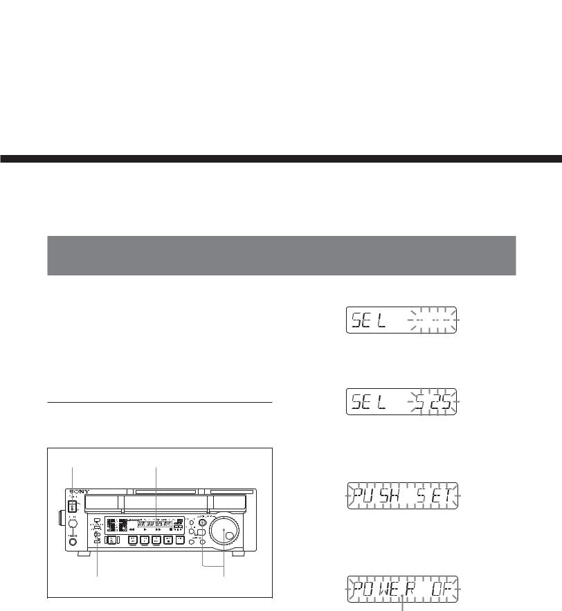
When using this unit for the first time, set the number of scan lines to the NTSC (525 scan lines, field frequency 60 Hz) system setting or to the PAL (625 scan lines, field frequency 50 Hz) system setting according to the operating environment in which the unit will be used. Otherwise, it will be impossible to use this unit.
To set this unit for the NTSC (525/60) or PAL (625/50) system
2 Holding down the JOG/SHUTTLE button, turn the JOG/SHUTTLE dial to display “525” or “625” next to “SEL”.
3 Press the SET/MENU button.
1,4 |
Time data display area |
|
|
|
|
|
|
4 |
|
3 |
2 |
1 Turn the POWER switch on. |
|
|
Indication “PUSH SET” appears in the time data display area.
Turn the POWER switch off, and then on again.
The indication in the time data display area changes as shown in the figure below.
You can see “POWER OFF/ON” by scrolling the indication.
When you turn on this unit for the first time, indication, “SEL ------” appears in the time data display area.
This unit is set for the 525/60 or 625/50 system and indicator 525 or 625 lights above the time data display area to show the selected system.
Chapter 1 Overview 1-1

Overview 1 Chapter
1-2 Features
The J-10/10SDI/30/30SDI (also referred to simply as the unit(s) in this manual) are compact players based on the 1/2-inch tape format.
They play tapes recorded in conventional Betacam/ Betacam SP format.
Notes
•Since the unit does not have a dynamic tracking function, the tape may not replay correctly if the recording pattern on the tape are disturbed.
•If you use a mobile radio machine with 5 W or larger output within 50 cm (19 3/4 inches) of this unit, the playback image may be disturbed.
The following are some of the features of these units.
Compatible format for playback
The unit can play tapes in the following formats:
•Digital Betacam format (J-30/30SDI only)
•MPEG IMX format (J-30/30SDI only)
•Betacam SX format
•Betacam/Betacam SP format
Head configuration
In addition to digital playback heads for the Digital Betacam (J-30/30SDI only), MPEG IMX (J-30/30SDI only) and Betacam SX, the unit also has analog playback heads for the analog Betacam SP.
Digital signal processing
This unit processes digital signals conforming to the 4:2:2 component digital D-1 format.
The unit is compatible with the Digital Betacam (J-30/ 30SDI only), the Betacam SX for the MPEG2 4:2:2 P@ML interframe format, and the MPEG IMX (J-30/30SDI only) for the MPEG2 4:2:2 P@ML intraframe format.
High image quality, high audio quality, high reliability
Complying with the data rates for the Digital Betacam (J-30/30SDI only), MPEG IMX (J-30/30SDI only) and Betacam SX, this unit achieves playback with both high image and high audio quality.
Playback compatibility with Betacam/ Betacam SP
The unit plays tapes recorded in the Betacam/Betacam SP format. This makes for efficient use of existing material in the Betacam/Betacam SP format.
Feeder function
This unit can be used not only as a Player but also as a Feeder. Connected to a PC, the unit controls images and feeds images to the PC via a remote connector (RS-422A) on the control panel.
Compact design
Since the unit is as compact as a standard desktop personal computer in size, it is ideal for personal use on your desktop. In addition, front loading of both S and L cassettes is standard.
Menu-based setup
Initial settings for the unit’s operation, interfaces with connected equipment, and so on, can be made by means of menu operations on the front panel of the unit.
A wide range of status indicators
A large-sized fluorescent display is provided to show numerical values including audio level, time code, user bits, error messages, and setup menu information in addition to the current settings and operating status of this unit.
Minimal maintenance
The unit is designed to need minimal maintenance, and requires no daily maintenance or checks.
A drum and other components have reduced maintenance costs.
Vertical installation
This unit can be installed vertically using the supplied vertical installation stands. The unit can be installed either vertically or horizontally, saving space on your desktop.
1-2 Chapter 1 Overview

Various output signals
The following interfaces installed on standard allow connection to various external devices.
•Analog composite video output
•Analog component video output (J-10/30 only)
•S-video output
• 1) (DV) output
•SDI SMPTE 259M (Component digital video/audio 8 channels) output (J-10SDI/30SDI only)
•Analog audio output
•Time code output (J-10SDI/30SDI only)
 (DV) output
This unit can output digital video/audio signals in DV format compatible with i.LINK1) from the DV output connector.
..........................................................................................................................................................................................................
1) is a trademark of Sony Corporation and indicates that this product is in agreement with IEEE 1394-1995 specifications and their revisions.
Overview 1 Chapter
Chapter 1 Overview 1-3
Overview 1 Chapter
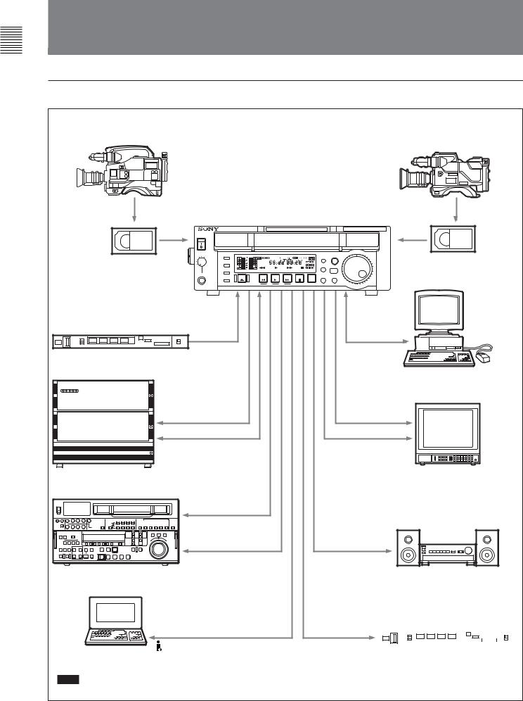
1-3 Sample System Configuration
Example for the J-10/10SDI
Betacam SX camcorder
Betacam SP camcorder
Digital cassette |
Analog cassette |
|
J-10/10SDI |
|
EXT SYNC |
Reference video signal generator |
|
|
SDI (J-10SDI) |
|
RS-422A |
Server |
|
|
a) |
|
SDI (J-10SDI) |
|
a) |
|
S video/analog composite/ |
VTR |
analog component (J-10) |
|
|
|
DV |
Computer |
|
a)
Note
Editing through this unit is not recommended.
JZ-1
RS-232C
Computer
SDI (J-10SDI)
S video/analog composite/ analog component (J-10)
Video monitor
Analog audio
Audio monitor
TC OUTPUT |
|
|
|
|
|
|
|
|
|
|
|
|
|
|
|
|
|
|
|
|
|
|
|
|
|
|
|
|
Time code reader |
|||||
(J-10SDI) |
|
|||||
|
|
|
|
|
|
|
1-4 Chapter 1 Overview

Example for the J-30/30SDI
MPEG IMX camcorder 


 Digital Betacam camcorder
Betacam SX camcorder
Betacam SP camcorder
MPEG IMX cassette |
Digital Betacam |
|
cassette |
Analog cassette
Digital cassette
|
|
J-30/30SDI |
|
|
EXT SYNC |
|
Reference video signal generator |
|
|
|
SDI (J-30SDI) |
|
|
RS-422A |
|
Server |
|
|
|
a) |
|
|
SDI (J-30SDI) |
|
|
a) |
|
|
S video/analog composite/ |
|
VTR |
analog component (J-30) |
|
|
|
|
Computer |
DV |
|
|
|
a) |
Note |
|
Editing through this unit is not recommended.
JZ-1
RS-232C
Computer
SDI (J-30SDI)
S video/analog composite/ analog component (J-30)
Video monitor
Analog audio
Audio monitor
TC OUTPUT |
|
|
|
|
|
|
|
|
|
|
|
|
|
|
|
|
|
|
|
|
|
|
|
Time code reader |
||||||||
(J-30SDI) |
|
|
||||||||
|
|
|
|
|
|
|
|
|
|
|
Overview 1 Chapter
Chapter 1 Overview 1-5

Chapter 2
Location and Function
of Parts
2-1 |
Control Panel |
|
|
|
1 Carrying handle |
|
|
|
2 POWER switch |
|
|
|
Display section |
|
Search control section |
|
(See page 2-2) |
|
(See page 2-6) |
|
|
3 Cassette compartment |
|
|
|
|
4 Remote control detector |
|
6 PHONES jack and |
Tape transport control |
5 PF-1/2 buttons |
|
control knob |
|
|
|
section (See page 2-7) |
|
|
|
|
|
1 Carrying handle |
2 POWER switch |
Use this handle to carry the unit or to stand the unit |
Press the side of the POWER switch marked “ON” to |
vertically. |
turn the unit on. The fluorescent display and indicators |
|
in the display section light. |
|
Press the side of the POWER switch marked “OFF” to |
|
turn the unit off. |
Parts of Function and Location 2 Chapter
Chapter 2 Location and Function of Parts |
2-1 |
Parts of Function and Location 2 Chapter
2-1 Control Panel
3 Cassette compartment
Insert an S or L cassette.
4 Remote control detector
Receives the infrared signal from the supplied Remote Commander.
For details on the Remote Commander, see section 4-3 “Using the Remote Commander” on page 4-6.
5 PF (programmable function)-1/2 buttons
When using the Betacam SX or MPEG IMX format and settting this unit into noiseless mode, use these buttons to perform frame step playback (see page 4-3). To the PF-2 button, you can assign functions that are set in basic menu item 022, PF2 KEYSELECT. Function “tape remain time” is assigned to the PF-2
button as the factory default settings. While you are pressing the button, the remaining tape time are displayed in the display section.
For details on function assignment, see the section “Menu bank operations (basic menu items B01 to B12) “ on page 7-5.
6 PHONES (headphones) jack and control knob
Connect stereo headphones with an impedance of 8 ohms to monitor the sound during playback. The control knob adjusts the volume.
It is possible to make a setting so that the output volume from the AUDIO MONITOR connectors is controlled simultaneously.
Set AUDIO MONITOR OUTPUT LEVEL, extended menu item 114, to VAR to enable the above feature.
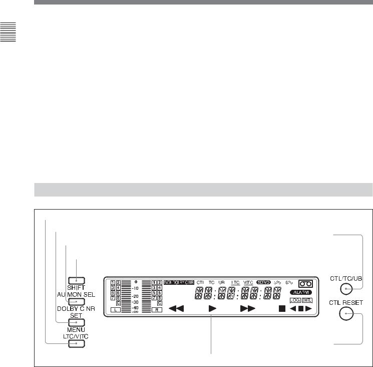
2-1-1 |
Display Section |
1 LTC/VITC button |
|
2 SET/MENU button |
|
|
5 CTL/TC/UB button |
3 AU MON SEL/DOLBY C NR button |
|
|
4 SHIFT button |
|
6 CTL RESET button |
|
7 FL (Fluorescent) display and indicators |
1 LTC/VITC button |
Note |
|
This selects the time code displayed in the FL display |
In this unit, VITC may not be displayed correctly |
|
in the following sequence: LTC1), VITC2). The |
except during normal playback. |
|
underline for the LTC or VITC time code setting |
|
|
indicators lights corresponding to the selection. |
|
|
..........................................................................................................................................................................................................
1) LTC: abbreviation of Longitudinal Time code. This |
2) VITC: abbreviation of Vertical Interval Time code. |
time code is recorded on a longitudinal track on the tape. |
This time code is inserted in the vertical blanking |
Reading is unreliable at low speeds, and not possible at |
interval and recorded on the video tracks. |
all during still playback. |
|
2-2 |
Chapter 2 Location and Function of Parts |

2 SET/MENU button
Use this button for setup menu operations and settings. Press the SET/MENU button while holding down the SHIFT button to display the contents of the setup menu items on the FL display. When the setting is finished, press only the SET/MENU button to fix the settings and return to the normal display.
For details of setup menu settings and operations, see Chapter 7.
3 AU MON SEL (audio monitor output select)/ DOLBY C NR1) (noise reduction) button
Press this button to function the AU MON SEL button. Each press of this button switches the audio channel as listed below. The selected channels are displayed in the display section.
For the Betacam/Betacam SP format
Output modea) |
STEREO |
|
MONO |
|
Audio channel |
L |
R |
L |
R |
Press once |
CH-1 |
CH-2 |
CH-1 |
CH-1 |
|
|
|
|
|
Press twice |
CH-1,2 |
CH-1,2 |
CH-2 |
CH-2 |
Press 3 times |
Each press of this |
CH-1,2 |
CH-1,2 |
|
|
button switches the |
|
|
|
Press 4 times |
Each press of this |
|||
|
mode as in the |
button switches the |
||
|
above sequence. |
|||
|
mode as in the |
|||
|
|
|
||
|
|
|
above sequence. |
|
|
|
|
|
|
a) Set in basic menu item 026 of the setup menu |
|
|||
For the Betacam SX format
Output modea) |
STEREO |
|
MONO |
|
|
Audio channel |
L |
R |
L |
R |
|
Press once |
CH-1 |
CH-2 |
CH-1 |
CH-1 |
|
|
|
|
|
|
|
Press twice |
CH-3 |
CH-4 |
CH-2 |
CH-2 |
|
|
|
|
|
|
|
Press 3 times |
CH-1,2 |
CH-1,2 |
CH-3 |
CH-3 |
|
|
|
|
|
|
|
Press 4 times |
CH-3,4 |
CH-3,4 |
CH-4 |
CH-4 |
|
|
|
|
|
|
|
Press 5 times |
Each press of this |
CH-1,2 |
CH-1,2 |
||
|
button switches the |
|
|
||
Press 6 times |
CH-3,4 |
CH-3,4 |
|||
|
mode as in the |
|
|
||
Press 7 times |
Each press of this |
||||
above sequence. |
|||||
|
|
|
button switches the |
||
|
|
|
mode as in the |
||
|
|
|
above sequence. |
||
|
|
|
|
|
|
a) Set in basic menu item 026 of the setup menu
For the MPEG IMX format (J-30/30SDI)
Output modea) |
STEREO |
|
|
MONO |
|
Audio channel |
L |
R |
L |
R |
|
Press once |
CH-1 |
CH-2 |
CH-1 |
CH-1 |
|
|
|
|
|
|
|
Press twice |
CH-3 |
CH-4 |
CH-2 |
CH-2 |
|
|
|
|
|
|
|
Press 3 times |
CH-5 |
CH-6 |
CH-3 |
CH-3 |
|
|
|
|
|
|
|
Press 4 times |
CH-7 |
CH-8 |
CH-4 |
CH-4 |
|
|
|
|
|
|
|
Press 5 times |
CH-1,2 |
CH-1,2 |
CH-5 |
CH-5 |
|
|
|
|
|
|
|
Press 6 times |
CH-3,4 |
CH-3,4 |
CH-6 |
CH-6 |
|
|
|
|
|
|
|
Press 7 times |
CH-5,6 |
CH-5,6 |
CH-7 |
CH-7 |
|
|
|
|
|
|
|
Press 8 times |
CH-7,8 |
CH-7,8 |
CH-8 |
CH-8 |
|
|
|
|
|
|
|
Press 9 times |
Each press of this |
CH-1,2 |
CH-1,2 |
||
|
button switches the |
|
|
||
Press 10 times |
CH-3,4 |
CH-3,4 |
|||
|
mode as in the |
|
|
|
|
Press 11 times |
above sequence. |
CH-5,6 |
CH-5,6 |
||
Press 12 times |
|
|
|
CH-7,8 |
CH-7,8 |
|
|
|
|
|
|
Press 13 times |
|
|
|
Each press of this |
|
|
|
|
|
button switches the |
|
|
|
|
|
mode as in the |
|
|
|
|
|
above sequence. |
|
|
|
|
|
|
|
a) Set in basic menu item 026 of the setup menu
For the Digital Betacam format (J-30/30SDI)
Output modea) |
STEREO |
|
|
MONO |
|
Audio channel |
L |
R |
L |
R |
|
|
|
|
|
|
|
Press once |
CH-1 |
CH-2 |
CH-1 |
CH-1 |
|
|
|
|
|
|
|
Press twice |
CH-3 |
CH-4 |
CH-2 |
CH-2 |
|
|
|
|
|
|
|
Press 3 times |
CH-1,2 |
CH-1,2 |
CH-3 |
CH-3 |
|
|
|
|
|
|
|
Press 4 times |
CH-3,4 |
CH-3,4 |
CH-4 |
CH-4 |
|
|
|
|
|
|
|
Press 5 times |
CUE |
CUE |
CUE |
CUE |
|
|
|
|
|
|
|
Press 6 times |
Each press of this |
CH-1,2 |
CH-1,2 |
||
|
button switches the |
|
|
|
|
Press 7 times |
|
CH-3,4 |
CH-3,4 |
||
mode as in the |
|
||||
|
|
|
|
||
Press 8 times |
|
Each press of this |
|||
above sequence. |
|||||
|
|
|
|
button switches the |
|
|
|
|
|
mode as in the |
|
|
|
|
|
above sequence. |
|
|
|
|
|
|
|
a) Set in basic menu item 026 of the setup menu
The latest setting for each format is saved in the memory regardless of whether the power has been turned on/off. Therefore, when you play any cassette next time, it will be played back in the format last saved. If there is no cassette in the unit, you can change the audio channel in the format used the last time you ejected the cassette.
..........................................................................................................................................................................................................
1)DOLBY C NR: Dolby C noise reduction manufactured under license from Dolby Laboratories Licensing Corporation. “DOLBY” and the double-D symbol  are trademarks of Dolby Laboratories Licensing Corporation.
Parts of Function and Location 2 Chapter
Chapter 2 Location and Function of Parts |
2-3 |

Parts of Function and Location 2 Chapter
2-1 Control Panel
Press this button while holding down the SHIFT button to function the DOLBY C NR button. The DOLBY C NR indicator lights in the display section. When you are using an oxide tape, it switches the Dolby NR C-type system for analog audio on or off. When you are using a metal tape, the Dolby C NR system is automatically switched on, regardless of the setting of this switch.
ON: Enables the Dolby C NR system for playback of an analog Betacam oxide tape.
OFF: Disables the Dolby C NR system for playback of an analog Betacam oxide tape.
The factory default setting is OFF.
4 SHIFT button
Hold down this button and press the AU MON SEL/ DOLBY C NR button to enable the DOLBY C NR function. To enable the menu function, press the SET/ MENU button while holding down the SHIFT button. Press the F FWD or REW button while holding down the SHIFT button to do the forward or reverse cue-up of the shot marks 1). These marks are located before and after of the current tape position. In addition, press the PLAY button while holding down the SHIFT button to superimpose the shot data2) (when using the Betacam/Betacam SP/Betacam SX format) or UMID (when using the Digital Betacam/ MPEG IMX format) over the playback image. To clear the shot data or UMID, again press the PLAY button while holding down the SHIFT button.
For details on UMID, see Chapter 5.
5 CTL/TC/UB (display switching) button
This selects the time data displayed in the fluorescent display in the following sequence: CTL, TC, UB. As the display changes, the corresponding indicators over the fluorescent display also light/go off.
Time data display selection and display contents
Display |
Value displayed |
Indicator status |
selection |
|
|
|
|
|
CTL |
Tape running time (hours, |
CTL indicator |
|
minutes, seconds, frames) |
lights. |
|
computed from the CTL |
|
|
(control) signal recorded on |
|
|
the tape during playback. |
|
|
|
|
TC |
Playback time code read by |
The TC indicator |
|
the internal time code |
lights. |
|
reader.a) |
|
UB |
User bit value inserted in the |
The UB indicator |
|
playback time code.a) |
lights. |
|
|
|
a) The LTC/VITC button switches between LTC and VITC.
6 CTL RESET button
Press this button to reset a CTL value displayed in the FL display area.
7 FL (Fluorescent) display and indicators
These comprise a time data display, an audio monitor display and of indicators. (See the figure on next page.)
..........................................................................................................................................................................................................
1)Shot marks
If you use a camcorder which allows you to use shot marks, you can insert REC START marks or shot marks in the user bits area in advance for easy editing.
This is called inserting shot marks.
2)Shot data
The information recorded continuously during the process of shooting is called shot data.
The contents of the display vary corresponding to the change of shooting conditions (e.g. changing camcorders, shooting on different dates, etc.). If there are any parts that contain no shot data by changing a shooting camcorder, the unit displays blank data.
Model |
name |
|
|
|
|
|
|
|
|
|
|
|
||
|
|
|
|
MODEL NAME |
|
DNW 0090 |
|
Serial number |
||||||
|
|
|
|
|
|
|||||||||
|
|
|
|
|
|
|
|
SERIAL NUMBER |
010001 |
|
|
|
||
Date |
|
|
|
|
|
|
|
|
|
|||||
|
|
|
|
|
DATE |
2001.05.11 |
|
|
|
Time |
||||
|
|
|
|
|
||||||||||
Cassette |
|
|
|
|
|
TIME |
|
12.55.10 |
|
|
|
|||
|
|
|
|
|
|
|
|
|
||||||
|
|
|
|
CASSETTE NUMBER |
0095 |
|
|
|
|
|||||
|
|
|
|
|
|
|||||||||
number |
|
|
|
|
SHOT NUMBER |
|
0052 |
|
|
|
Shot number |
|||
|
|
|
|
|
|
|
|
ID1 |
AAAAAAAAAAAA |
|
|
|||
|
|
|
|
|
|
|
|
ID2 |
BBBBBBBBBBBB |
|
Camera ID |
|||
|
|
|
|
|
|
|
|
ID3 |
CCCCCCCCCCCC |
|
||||
|
|
|
|
|
|
|
|
|
|
|||||
|
|
|
|
|
|
|
|
ID4 |
DDDDDDDDDDDD |
|
|
|||
|
|
|
|
|
|
|
|
TCR 23:59:59:29 |
|
Time code |
||||
|
|
|
|
|
|
|
|
|
|
|
|
|
|
at recording |
|
|
|
|
|
|
|
|
|
|
|
|
|
||
2-4 |
Chapter 2 Location and Function of Parts |
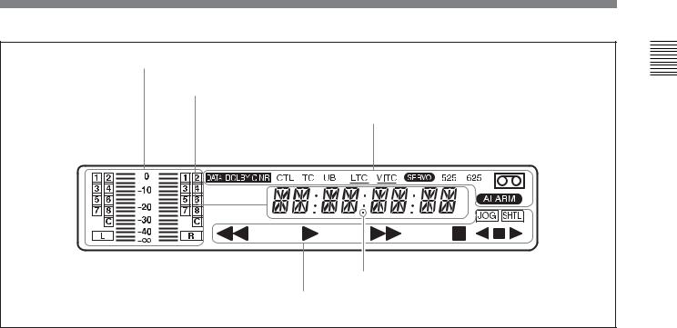
Audio monitor display area
Time data display area
Indicator area
Tape transport indicator area
Audio monitor display area
•L/R audio level meter
Indicates the audio levels of the 2 optionally selected channels making up L/R (Left/Right).
•L/R audio channel display
Indicates the optionally selected channel numbers.
Time data display area
Normally this displays a CTL count, time code value, or user bit value according to the selection of the CTL/ TC/UB button or LTC/VITC button. When a cassette recorded in the DF mode is played back, the dot by themark in the illustration above lights. At this time, the two dots (:) located above the dot disappear.
It is also used to display error messages and the setup menus.
For details of the display of the CTL count, time code value, or user bit value, see the explanation given in “5 CTL/TC/ UB button” on page 2-4.
Indicator area
This includes the following indicators.
•DOLBY C NR (Dolby C noise reduction) indicator: This lights when the Dolby noise reduction circuit is functioning..
•CTL (control) indicator: This lights when a tape running time (hours, minutes, seconds, frames) computed from the CTL signal is displayed in the time data display area.
•TC (time code) indicator: This lights when a time code is displayed in the time data display area.
•UB (user bits) indicator: This lights when a user bit value is displayed in the time data display area.
•LTC, VITC indicators: Regardless of the display in the time data display area, these indicators light when the corresponding time code values are being read.
When LTC has been selected using the LTC/VITC button, the LTC indicator is displayed and underlined. On the other hand, when VITC is selected, the VITC indicator is displayed and underlined.
•SERVO indicator: This lights when the servo lock is functioning.
•ALARM indicator: This lights when a hardware error is detected on the unit, and goes off when the error is resolved. When this indicator is lit, an error message appears in the time data display area.
•Cassette-in indicator q: This lights when a cassette is loaded in the unit.
•DATA indicator: This lights when a tape, containing audio data such as Dolby-E and AC-3 on its DIGITAL AUDIO track, is played back.
•525, 625 (scan lines for the television standard) indicators: Either of these indicators lights to show the system for which this unit is set in basic menu item 013 (NTSC: 525 scan lines, field frequency 60 Hz; PAL: 625 scan lines, field frequency 50 Hz).
Parts of Function and Location 2 Chapter
Chapter 2 Location and Function of Parts |
2-5 |
Parts of Function and Location 2 Chapter
2-1 Control Panel
Tape transport indicator area
•Tape transport indicator
When you press each button in the tape transport control section, the corresponding indicators light. m: REW (rewind) indicator
B: PLAY indicator
When AUTO TRACKING (the automatic tape loading function) is in operation, this indicator flashes.
M: F FWD (fast forward) indicator x: STOP indicator
•JOG/SHTL (jog/shuttle) indicator
The “JOG” indicator lights when playback is carried out in jog mode, and the “SHTL” indicator lights when playback is carried out in shuttle mode.
•JOG/SHTL (jog/shuttle) transport indicator b: Jog/shuttle reverse indicator (green)
B: Jog/shuttle forward indicator (green) x: Jog/shuttle still indicator (red)
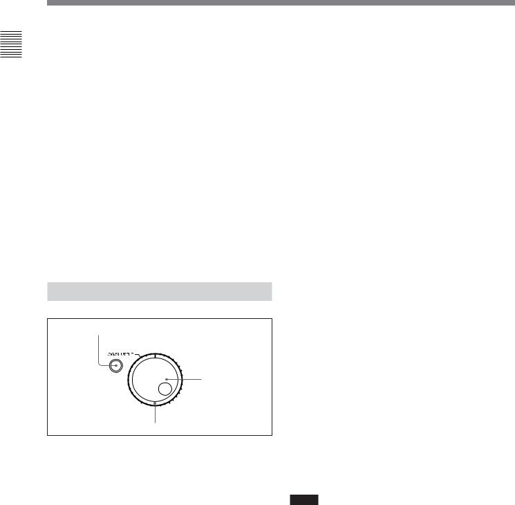
2-1-2 Search Control Section
1 JOG/SHUTTLE button
2 JOG dial
3 SHUTTLE dial
1 JOG/SHUTTLE button
Use this button to toggle between jog mode and shuttle mode when using the JOG dial or SHUTTLE dial. Press this button once for playback in jog mode, or press this button twice for playback in shuttle mode during playback or F FWD/REW. The corresponding “JOG” indicator or “SHTL” indicator lights in the display section.
2 JOG dial
Turn this to carry out playback in the modes shown in the table in the right column. Turn the dial clockwise for forward playback and counterclockwise for reverse playback.
3 SHUTTLE dial
Turn this to carry out playback in the modes shown in the following table. Turn the dial clockwise for forward playback and counterclockwise for reverse playback.
After pressing the JOG/SHUTTLE button, turn the JOG dial for playback in jog mode and the SHUTTLE dial for playback in shuttle mode.
Playback modes using the JOG/SHUTTLE dial
Playback mode |
Operations and functions |
|
|
Jog |
Press the JOG/SHUTTLE button once to |
|
light “JOG,” then turn the JOG dial, or |
|
simply turn the JOG dial without lighting |
|
“JOG.” Playback is carried out at a |
|
speed corresponding to the rotating |
|
speed of the JOG dial. The playback |
|
speed range is from –1 to +1 times |
|
normal speed. |
|
The JOG dial has no detents. |
|
|
Shuttle |
Press the JOG/SHUTTLE button twice to |
|
light “SHTL,” then turn the SHUTTLE |
|
dial, or simply turn the SHUTTLE dial |
|
without lighting “SHTL.” Playback is |
|
carried out at a speed corresponding to |
|
the angular position of the SHUTTLE |
|
dial. The playback speed range is as |
|
follows. |
|
When using a Digital Betacam tape |
|
(J-30/30SDI): –21 to +21 times normal |
|
speed |
|
When using an MPEG IMX tape (J-30/ |
|
30SDI): –32/–38 to +32/+38 times |
|
normal speed (NTSC/PAL) |
|
When using a Betacam SX tape: –35 |
|
to +35 times normal speed |
|
When using an analog Betacam tape: |
|
–18/–20 to +18/+20 times normal |
|
speed (NTSC/PAL) |
|
The SHUTTLE dial has detents at the |
|
center position, and at that point a still |
|
picture is displayed. |
|
|
Notes
•Normally, you turn the SHUTTLE dial after setting the jog/shuttle mode by pressing the JOG/SHUTTLE button. However, you can also set the jog/shuttle mode simply by turning the dial. (This feature is available when SELECTION FOR JOG/SHUTTLE DIAL ENABLE, extended menu item 101 of the setup menu, is set to DIAL.) In this case, you must reset the SHUTTLE dial to the center position after turning it, otherwise the dial may be moved by vibration and the tape may start running in the shuttle mode during playback.
2-6 |
Chapter 2 Location and Function of Parts |
•If the unit carries out reverse playback in the shuttle mode at –0.5 times or less normal speed for 20 consecutive minutes, the reel motor heat protection circuit automatically functions and the unit enters still mode.
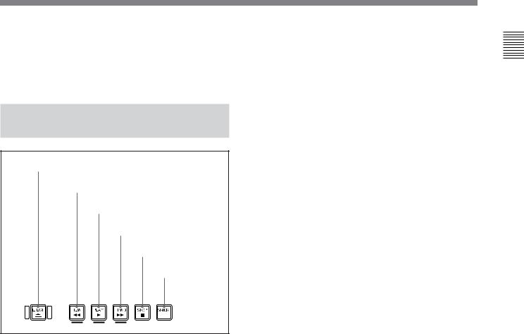
2-1-3 Tape Transport Control
Section
1 EJECT button
2 REW button
3 PLAY button
4 F FWD button
5 STOP button
6 STANDBY on/off button
1 EJECT button
Press this button to eject the cassette.
2 REW (rewind) button
To rewind the tape, press this button. The REW indicator in the display section lights. When you are using a tape containing shot marks, press this button while holding down the SHIFT button to cue-up a shot mark position in the reverse direction.
3 PLAY button
To start playback, press this button. The PLAY indicator in the display section lights.
When you are using a Betacam/Betacam SP/Betacam SX tape containing shot data, press this button while holding the SHIFT button to display shot data (see page 2-4).
When you are using a Digital Betacam/MPEG IMX tape containing UMID, press this button while holding the SHIFT button to display UMID (see page
5-2).
To clear the shot data or UMID, again press this button while holding down the SHIFT button.
4 F FWD (fast forward) button
To start fast forwarding the tape, press this button. The F FWD indicator in the display section lights. When you are using a tape containing shot marks, press this button while holding down the SHIFT button to cue-up a shot mark position in the forward direction.
5 STOP button
To stop playback, press this button. The STOP indicator in the display section lights.
If REFERENCE SYSTEM ALARM, extended menu item 105 of the setup menu, has been set to ON, this button flashes when the external reference video signal is not supplied.
6 STANDBY on/off button
When a cassette is inserted in the unit and the unit is in the Stop mode, you can toggle the VTR standby mode on and off by pressing this button.
In standby mode, the drum rotates and the tape sticks to the drum. As a result, playback starts immediately. If the unit is set to 8 minutes elapse (this value can be varied using STILL TIMER extended menu item 501 of the setup menu) in standby mode, it automatically switches out of standby mode to protect the tape.
Parts of Function and Location 2 Chapter
Chapter 2 Location and Function of Parts |
2-7 |
 Loading...