


KD-60X690EKD
Table of contents
 Loading...
SERVICE MANUAL
Version Date Subject
1.0 2017/6/27 First version issue.
LCD Digital Color T V
9-888-740-01
HISTORY INFORMATION FOR THE FOLLOWING MANUAL:
ORIGINAL MANUAL ISSUE DATE: 2017/6/27
GN3FK CHASSIS
Segment: KCL

MODEL LIST
MODEL COLOR COMMANDER DEST. MODEL COLOR COMMANDER DEST.
KD-60X690E Black RMT-TX300U UC2/LA1
KD-70X690E Black RMT-TX300U UC2/LA1
KD-60X695E Black RMT-TX300B AR4/LA8
KD-60X697E Black RMT-TX300B CO1
KD-60X6700E Black RMT-TX300E/300P AZ1/ME6/EA4
KD-70X6700E Black RMT-TX300E/300P AZ1/ME6/EA4
2
KD-60X690E/KD-70X690E(UC2/LA1)/KD-60X695E(AR4/LA8)/KD-60X697E(CO1)/KD-60X6700E/KD-70X6700E(AZ1/ME6/EA4)

WARNINGS AND CAUTION S
CAUTION
These servicing instructions are for use by qualified service personnel only.
To reduce the ri sk o f ele ct ri c sho c k, d o not perfo r m any se r vici ng other than t hat c o nta ine d i n the op e ra ti ng instr uc tio ns unless you are qualified to do so.
WARNING!!
An isolation transformer should be used during any service to avoid possible shock hazard, because of live chassis.
The chassis of this receiver is directly connected to the ac power line.
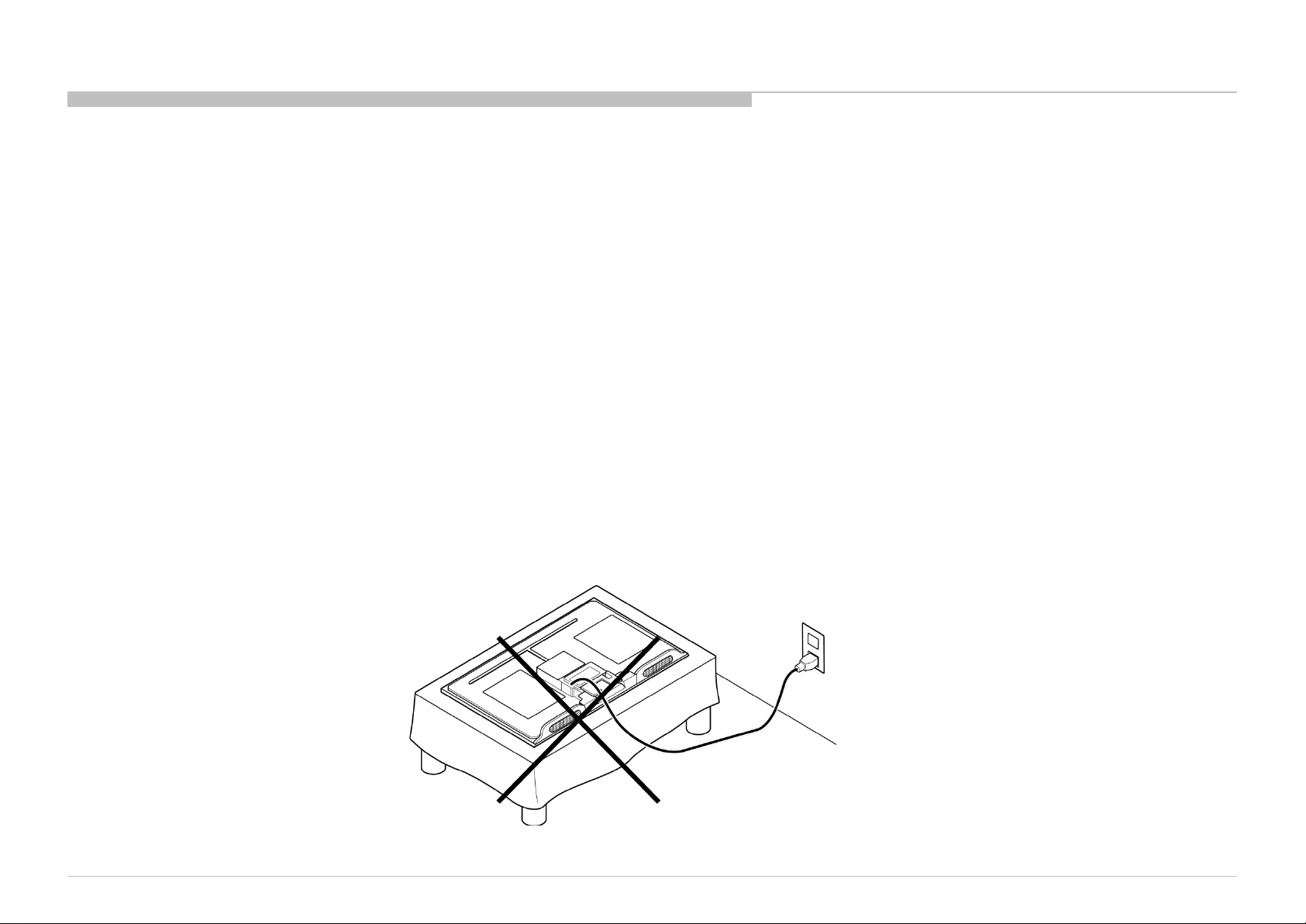
CARRYING THE TV
Be sure to follow these guidelines to protect your property and avoid causing serious injury.
• Carry the TV with an adequate number of people; larger size TVs require two or more people.
• Correct hand placement while carrying the TV is very important for safety and to avoid damages.
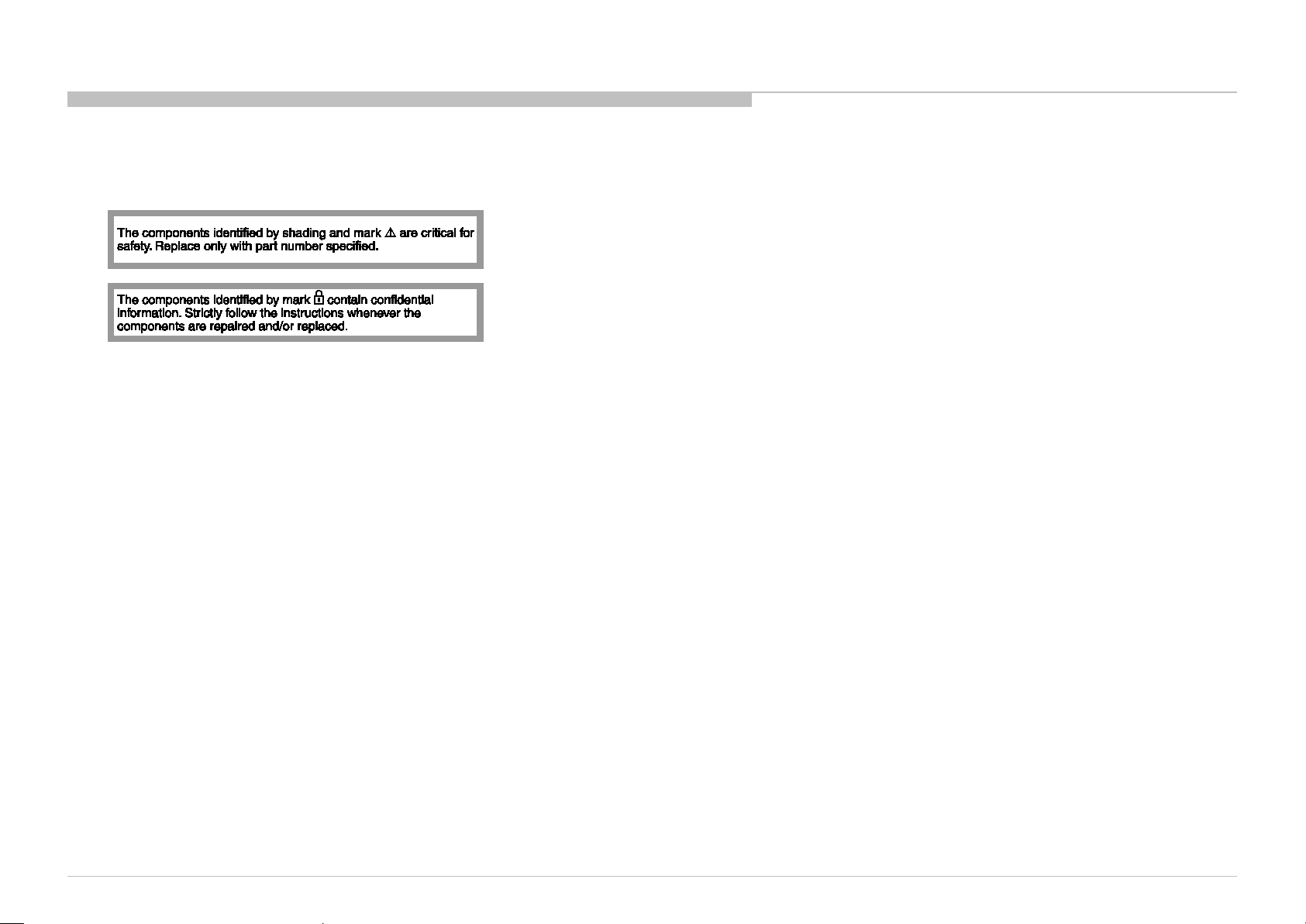
SAFETY-RELATED COMPONENT WARNING!!
Components identified by shading and ! mark on the schematic diagrams, exploded views, and in the parts list are critical for safe operation. Replace these components with Sony
parts whose part numbers appear as shown in this manual or in supplements published by Sony. Circuit adjustments that are critical for safe operation are identified in this manual.
Follow these procedures whenever critical components are replaced or improper operation is suspected.
3
KD-60X690E/KD-70X690E(UC2/LA1)/KD-60X695E(AR4/LA8)/KD-60X697E(CO1)/KD-60X6700E/KD-70X6700E(AZ1/ME6/EA4)
When re pa ir ing the LCD p a nel, b e sure you ar e gr o und ed b y using a wrist b and .
When repa ir ing the LCD p a nel o n the wall, the LCD panel must b e sec ur ed using the 4 mounting ho le s o n the r ea r c o ver .
1) Do not press on the panel or frame edge to avoid the risk of electric shock.
2) Do not scratch or press on the panel with any sharp objects.
3) Do not l eave the module in high t emperatures or in areas of high humidity for an extended perio d of time.
4) Do not expose the LCD panel to direct sunlight.
5) Avoid contact with water. It may cause a short circuit within the module.
6) Disconnect the AC power when replacing the backlight (CCFL) or inverter circuit. (High voltage occurs at the inverter circuit at 650Vrms.)
7) Always clean the LCD panel with a soft cloth material.
8) Use care when handling the wires or connectors of the inverter circuit. Damaging the wires may cause a short.
9) Protect the panel from ESD to avoid damaging the electronic circuit (C-MOS).
10) It is recommended not to exceed 1 hour of Power-On nor Burn-in period with LCD panel face down conditio n, in repair activity.
4
USE CAUTION WHEN HANDLING THE LCD PANEL
KD-60X690E/KD-70X690E(UC2/LA1)/KD-60X695E(AR4/LA8)/KD-60X697E(CO1)/KD-60X6700E/KD-70X6700E(AZ1/ME6/EA4)

SAFETY CHECK-OUT
After correcting the original service problem, perform the following safety checks before releasing the set to the customer:
1. Check the area of your repair for unsoldered or poorly soldered connections. Check the entire board surface for solder splashes and bridges.
2. Check the interboard wiring to ensure that no wires are “pinched” or touching high-wattage resistors.
3. Check that all control knobs, shields, covers, ground straps, and mounting hardware have been replaced. Be absolutely certain that you have replaced all the insulators.
4. Look for unauthorize d replacement parts, particularly transistors, that were installed during a pre vious repair. Point them out to the customer and recommend their replacement.
5. Look for par ts which, though functio ning, show obvi ous s igns o f d et er io r ati o n. P o int them out to the cust o mer a nd re c ommend their replacement.
6. Check the line cords for cracks and abrasion. Recommend the replacement of any such line cord to the customer.
7. Check the antenna terminals, metal trim, “metallized” knobs, screws, and all other exposed metal parts for AC leakage. Check leakage as described below.
8. For safety reasons, repairing the Power board and/or Inve rt er board is prohibited.
5
KD-60X690E/KD-70X690E(UC2/LA1)/KD-60X695E(AR4/LA8)/KD-60X697E(CO1)/KD-60X6700E/KD-70X6700E(AZ1/ME6/EA4)
SAFETY CHECK-OUT
6
Leakage Test
(To protect electric shock when customer touch the term inal.)
Leakage current can be m easured by V: Voltmeter or oscilloscope (r.m.s. or peak reading)
Stabilized power supply instrument and isolated voltage transformer: Use too much current capacity and
isolated voltage transformer does not need to use stabilized power supply equipment Specification of RMS v olt
meter: Input resistance > 1 M ohm, Input capacitance < 200 pF, Frequency range: 15 Hz – 1MHz (Refer Figure
A). Isolated type volt -m eter (FLUKE 8921A etc *1)
*1 Not use FLUKE 8920A that connected to protective earth by diode
# Leakage current of measurement instrument is less than 10μArms when under test equipment AC plug is
opened # Set up the following condition and turn on the set.
Applied voltage: Nominal input voltage (Description on Nameplate) # Measure the leakage current between
one phase conductor and neutral for terminal A and terminal B.
Read rms value, and then calculate to peak value PEAK VALUE =√2 RMS VALUE
Comply with the following requirement Class II equipment (2-pin plug): for each terminal, the worst value of
measurement must not exceed AC 350uA peak). Note: including AC adaptor, AC adaptor/DC operated unit
combination
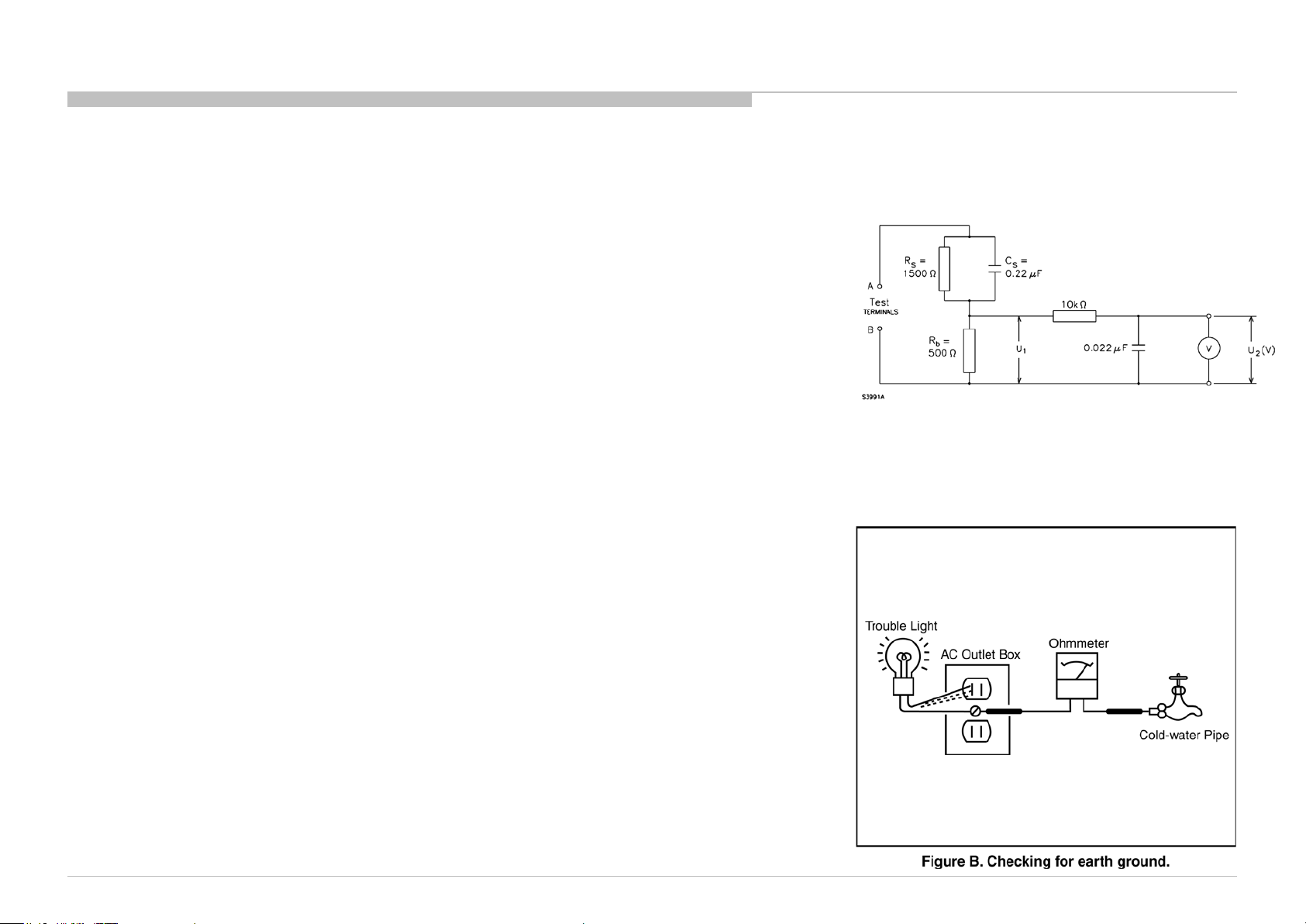
How to Find a Good Earth Ground
A cold-water pipe is a guaranteed earth ground; the cover-plate retaining screw on most AC outlet boxes is also
at earth ground.
If the retaining screw is to be used as your earth ground, verify that it is at ground by measuring the resistance
between it and a cold-water pipe with an ohmmeter. The reading should be zero ohms.
If a cold-water pipe is not accessible, connect a 60- to 100-watt trouble- light (not a neon lamp) between the hot
side of the receptacle and the retaining screw. Try both slots, if necessary, to locate the hot side on the line; the
lamp should light at normal brilliance if the screw is at ground potential (see Figure B).
Figure A. Measuring network for Leakage Current
KD-60X690E/KD-70X690E(UC2/LA1)/KD-60X695E(AR4/LA8)/KD-60X697E(CO1)/KD-60X6700E/KD-70X6700E(AZ1/ME6/EA4)
SELF DIAGNOSIS FUNCTION
7
KD-60X690E/KD-70X690E(UC2/LA1)/KD-60X695E(AR4/LA8)/KD-60X697E(CO1)/KD-60X6700E/KD-70X6700E(AZ1/ME6/EA4)
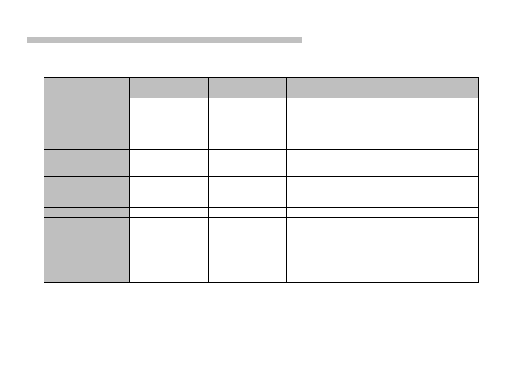
Error Items
Number of LED
flashing
Go to Shutdown
State
Description
MAIN_POWER
2
Yes
Detect and observe main voltage
(1) 19.5V from AC adapter
(2) 12V from power board (TBD)
AUD_ERR
3
Yes
Detecting/Observing audio AMP error
AUD_I2C
3
Yes
Audio AMP communication error
TU_DEMOD
-
No
(Only record error
log)
Tuner & Demodulator I2C communication
monitoring.
Tuner Detect signal monitoring.
PANEL_POWER_ERR
4
Yes
Detect and observe for Panel_12V
PANEL_I2C_ERR
5
Yes
Detect Panel I2C Communication access error
BACKLIGHT
6
Yes
Detect and observe backlight error
LED_I2C
6
Yes
LED Driver commu nication error
BE_I2C
-
No
(Only record error
log)
BE device I2C communication error detection.
PMIC_I2C
-
No
(Only record error
log)
PMIC communication erro r
8
KD-60X690E/KD-70X690E(UC2/LA1)/KD-60X695E(AR4/LA8)/KD-60X697E(CO1)/KD-60X6700E/KD-70X6700E(AZ1/ME6/EA4)
SELF DIAGNOSIS FUNCTION
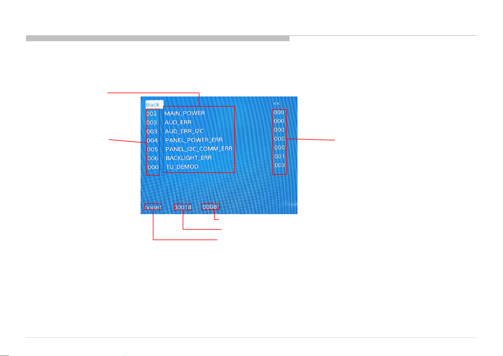
[SELF DIAGNOSTIC SCREEN DISPL AY]
Error count
Item name
STBY LED flash time
Total operation time by hour
Boot count
Panel operation time by hour
Since the diagnostic results displayed on the screen are not automatically cleared, always check the self-diagnostic screen.
After you have completed the repairs, clear the result display to “0”.
Clearing the Self Check Diagnostic List
1. Error history and Error count : Press the Channel 8 => Channel 0 .
2. Panel operation time : Press the Channel 7 => Channel 0 .
Exiting the Self-diagnostic screen
To exit the Self Diagnostic screen, turn off the power to the TV by pressing the POWER button on the remote or the POWER button on the TV.
• Items with no part number and no description are not stocked because they are seldom required for roution service.
• The construction parts of an assembled part are indicated with a collation number in the remark colum.
• Items marked " * " are not stocked since they are seldom required for routine service. Some delay should be anticipated when ordering these items.
SEC 1. DISASSEMBLY AND PARTS LIST
9
KD-60X690E/KD-70X690E(UC2/LA1)/KD-60X695E(AR4/LA8)/KD-60X697E(CO1)/KD-60X6700E/KD-70X6700E(AZ1/ME6/EA4)

DISASSEMBLY AND PARTS LIST
10
1-2. KD-60X690E/KD-60X695E/KD-60X697E/KD-60X6700E
KD-60X690E(UC2/LA1)/KD-60X695E(AR4/LA8)/KD-60X697E(CO1)/KD-60X6700E(AZ1/ME6/EA4)
4
-723-296-01 SCREW, +PSW M5X12
7
-682-961-09 SCREW, +PSW M4x8 W8
4
-729-979-01 SCREW,F,CROSS,T.T-3*6,BLK-ZN.
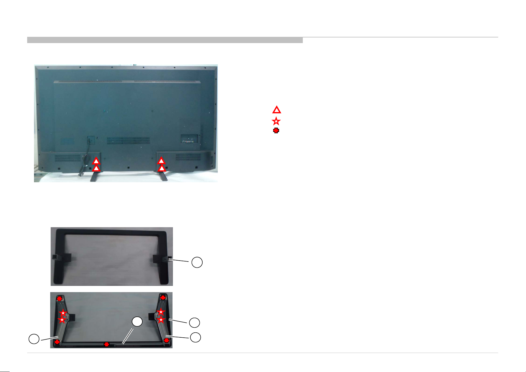
1-2-1. STAND BLOCK
1-2-2. STAND COVER ASSY AND ST AND BASE ASSY AND NE CK
1
REF.NO. PART No.
DESCRIPTION
MARK
1 4-723-281-01
STAND, NECK
2 4-723-280-01
STAND, COVER
3 4-723-282-01
STAND, BRACKET L
4 4-723-283-01
STAND, BRACKET R
5 4-723-284-01
STAND, BRACKET FRONT
2
3
4
5
DISASSEMBLY AND PARTS LIST
11
1-2. KD-60X690E/KD-60X695E/KD-60X697E/KD-60X6700E
KD-60X690E(UC2/LA1)/KD-60X695E(AR4/LA8)/KD-60X697E(CO1)/KD-60X6700E(AZ1/ME6/EA4)
4-729-978-01 SCREW, +PSW M3X8 W8
4-268-126-02 SCREW,ORNAMENTAL M6X12
7-685-646-79 SCREW, +BVTP 3X8 TYPE2 IT-3
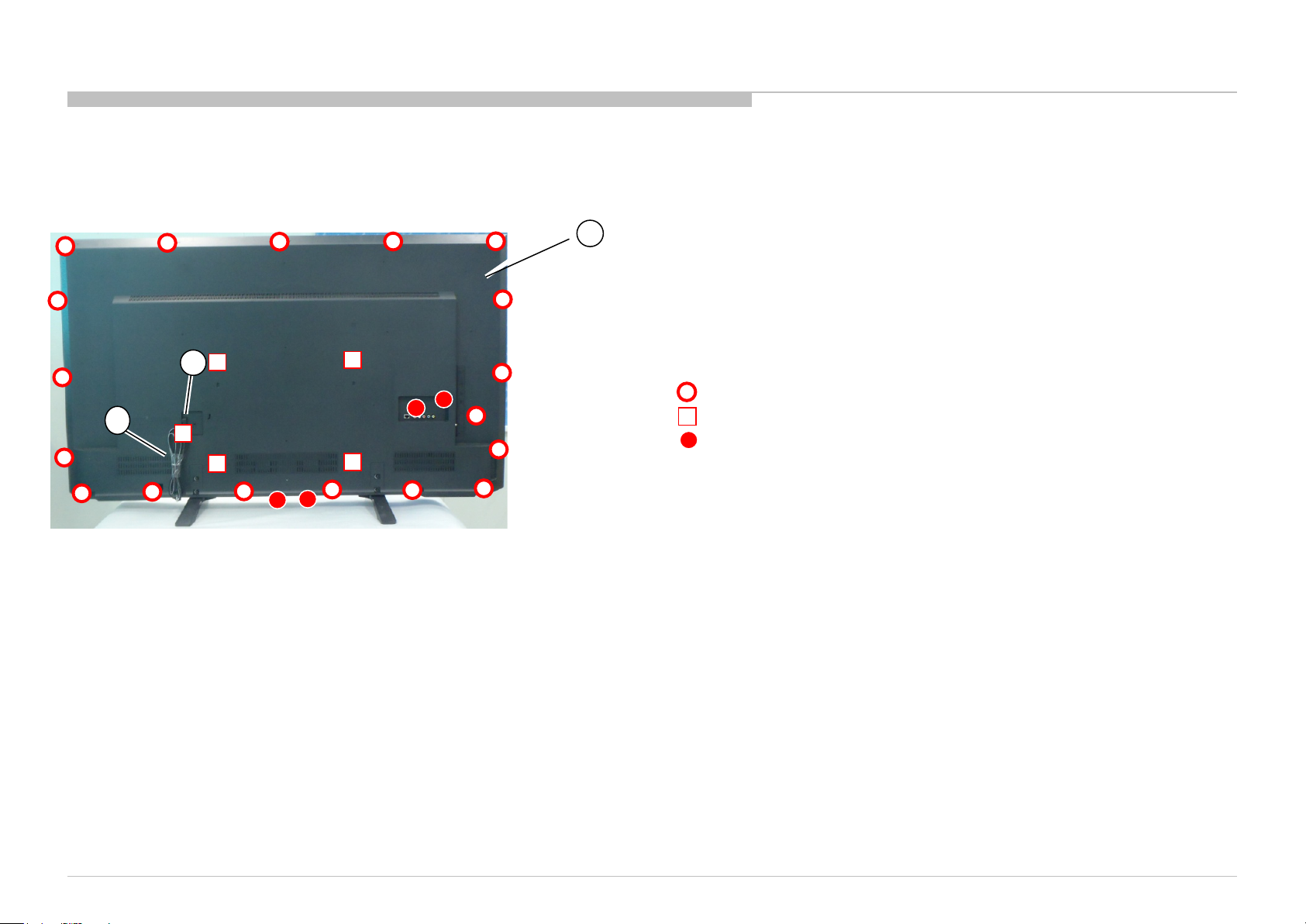
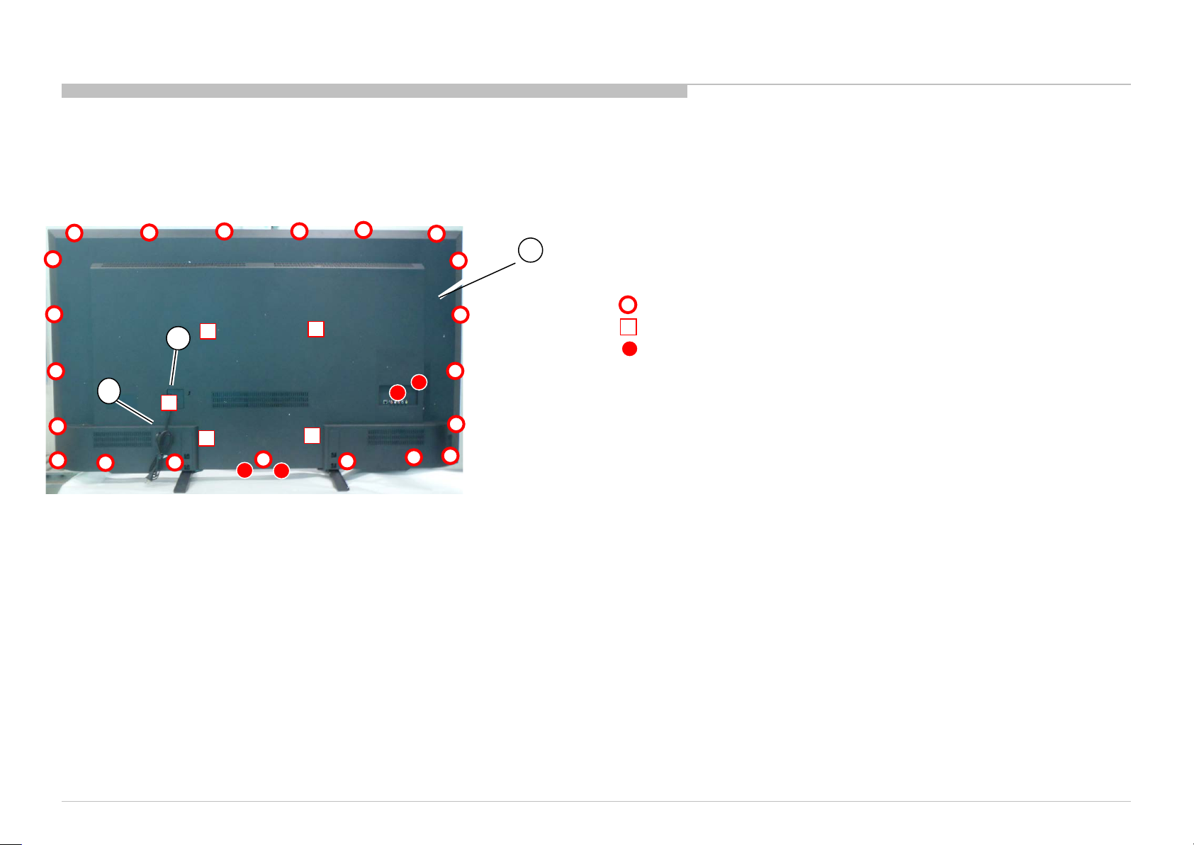
1-2-3. AC COVER AND R E AR C O VE R
REF.NO. PART No. DESCRIPTION MARK
6 4-725-317-01 COVER, AC
7 1-912-305-11 AC Cord(USA 2pin) For UC2/LA1/CO1
1-912-304-11 AC Cord(Argentina 2pin) For AR4
1-912-303-11 AC Cord(Europe 2pin) For LA8/ME6
1-912-301-11 AC Cord(UK 3pin) For EA4
1-912-302-11 AC Cord(AUS/NZ 2pin) For AZ1
8 4-723-275-01 COVER, REAR (UC2) ForUC2
4-723-277-01 COVER, REAR (LA1/EA4/ME6) ForLA1/EA4/ME6
4-723-276-01 COVER, REAR (LA8/CO1/AR4 ) ForLA8/CO1/AR4
4-723-298-01 COVER, REAR (AZ1) ForAZ1
8
6
7
DISASSEMBLY AND PARTS LIST
12
1-2. KD-60X690E/KD-60X695E/KD-60X697E/KD-60X6700E
KD-60X690E(UC2/LA1)/KD-60X695E(AR4/LA8)/KD-60X697E(CO1)/KD-60X6700E(AZ1/ME6/EA4)
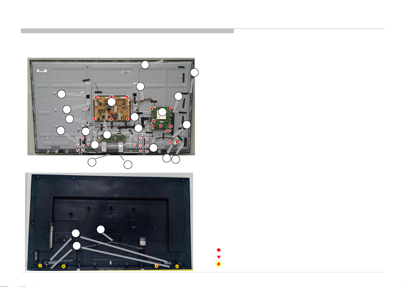
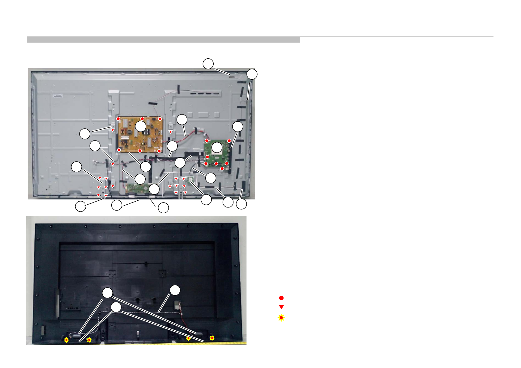
1-2-4. OVERALL
18
25
28
13
10
12
24
27
17
9
15
14
21
REF.NO.
PART No.
DESCRIPTION
MARK
9
1
-522-035-11 ANTENNA 1 (W)
10
1
-522-033-11 ANTENNA 2 (B)
11
1
-897-219-11 MOUNTED PWB POWER UNIT
12
1
-897-214-11 MOUNTED PWB A
For
UC2
1
-897-209-11 MOUNTED PWB A
For LA8
1
-897-217-11 MOUNTED PWB A
For
LA1
1
-897-211-11 MOUNTED PWB A
For AR4
1
-897-210-11 MOUNTED PWB A
For
CO1
1
-897-208-11 MOUNTED PWB A (AZ1, ME6, EA4)
For AZ1/ME6/EA4
13
1
-897-212-11 MOUNTED PWB H
14
1
-897-213-11 MOUNTED PWB KEY
15
1
-897-207-11 MOUNTED PWB WF
16
1
-910-112-59 CONNECTOR ASSY 15P (MB-PSU)
17
1
-910-112-60 CONNECTOR ASSY (MB-SPK 1)
18
1
-910-112-61 CONNECTOR ASSY (MB-SPK 2)
19
1
-910-112-56 LVDS CABLE 41P (MB-Panel)
20
1
-910-112-57 CONNECTOR ASSY 10P (MB-IR)
21
1
-910-112-58 CONNECTOR ASSY 6P (MB-key)
22
1
-910-112-63 CONNECTOR ASSY (PSU-Panel)
23
1
-910-112-62 CONNECTOR ASSY (MB-WIFI)
24
1
-859-242-11 SPEAKER 12W
25
4
-723-286-01 SHEET, INSULATION
26
4
-723-287-01
DECO
27
4
-545-671-01 BRACKET, VESA (60)
28
4
-723-278-01 BRACKET, BOTTOM
29
4
-723-297-01 BRACKET, SIDE IO
For UC2/LA1/
EA4/ME6/AZ1
4
-723-279-01 BRACKET, SIDE IO (LA8/CO1/AR4)
For LA8/CO1/AR4
30
4
-729-982-01 CUSHION W25*T5
31
4
-723-294-01 CLAMP, CABLE
32
4
-729-986-01 NWF 145*8*0.35mm
16
20
19
26
2
-990-421-41
SCREW(PSW)(M3X6)
4
-729-978-01
SCREW, +PSW M3X8 W8
4
-459-864-01
SCREW, +PWTP2 4X10
31
29
11
30
22
23
32
DISASSEMBLY AND PARTS LIST
13
1-2. KD-60X690E/KD-60X695E/KD-60X697E/KD-60X6700E
KD-60X690E(UC2/LA1)/KD-60X695E(AR4/LA8)/KD-60X697E(CO1)/KD-60X6700E(AZ1/ME6/EA4)
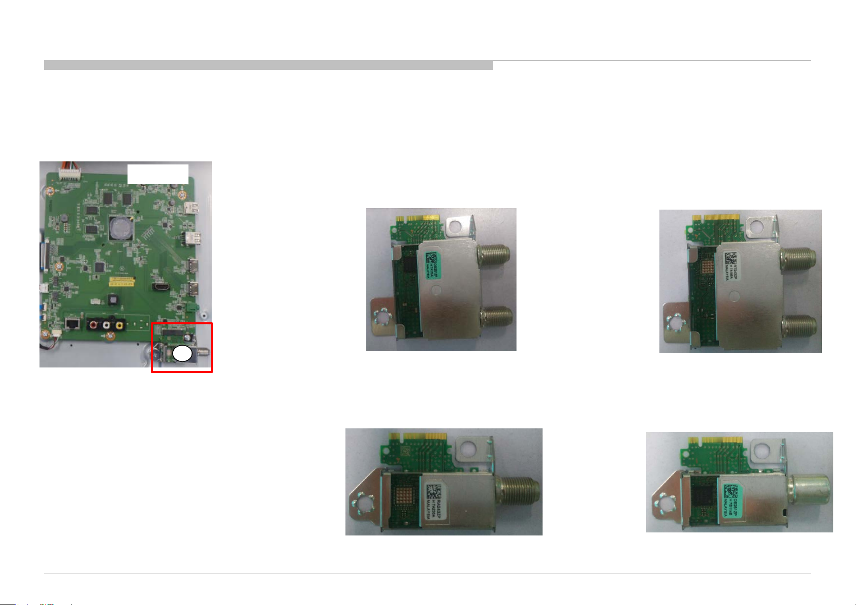
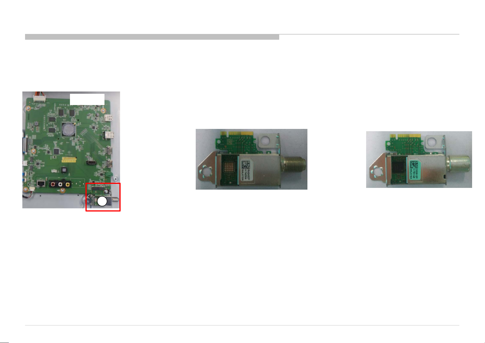
A BOARD
33
REF.NO.
PART No.
DESCRIPTION
MARK
33
8-594-302-70
TUNER MODULE SUT
-RA243ZP
For UC2/LA1
8-594-308-30
TUNER MODULE SUT
-RT243ZP
For LA8/AR4
8-594-325-00
TUNER MODULE SUT
-DB251ZP
For CO1
8-594-328-10
TUNER MODULE SUT
-DE251ZP
For AZ1/EA4/ME6
1-2-5. TUNER MODULE
For CO1
For AZ1/EA4/ME6
For UC2/LA1
For LA8/AR4
14
DISASSEMBLY AND PARTS LIST
1-2. KD-60X690E/KD-60X695E/KD-60X697E/KD-60X6700E
KD-60X690E(UC2/LA1)/KD-60X695E(AR4/LA8)/KD-60X697E(CO1)/KD-60X6700E(AZ1/ME6/EA4)
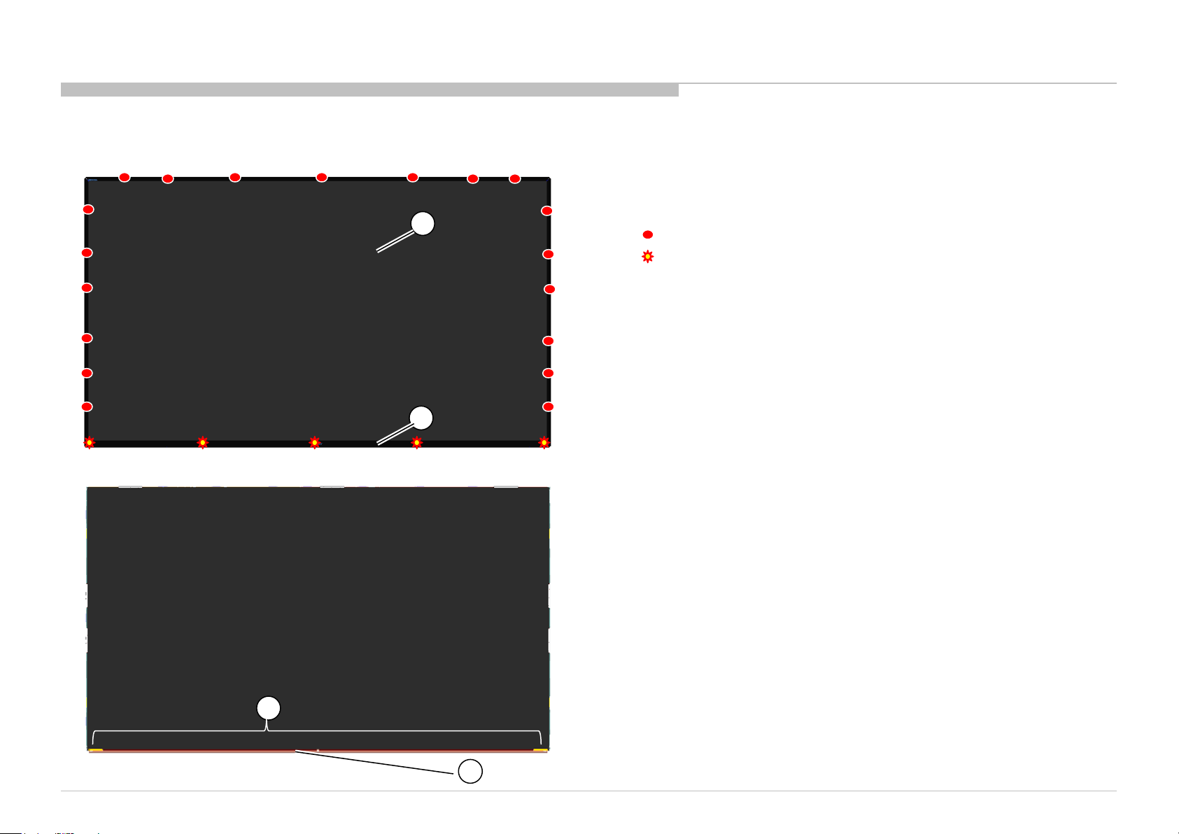
1-2-6. LCM
34
35
36
REF.NO. PART No. DESCRIPTION
MARK
34
1-812-368-11 LCM ASSY (60) (S600DUC-1)
35
4-724-143-01 BEZEL, FRONT
36
4-729-983-01 FC BTM BRACKET (60)
37
4-729-985-01 Double Side Tape
1-2-7. LCM (W/O BEZEL)
37
4
-729-980-01
SCREW,A,M2.5,L5
4
-729-981-01
SCREW(B)/M2.5*L10
15
DISASSEMBLY AND PARTS LIST
1-2. KD-60X690E/KD-60X695E/KD-60X697E/KD-60X6700E
KD-60X690E(UC2/LA1)/KD-60X695E(AR4/LA8)/KD-60X697E(CO1)/KD-60X6700E(AZ1/ME6/EA4)
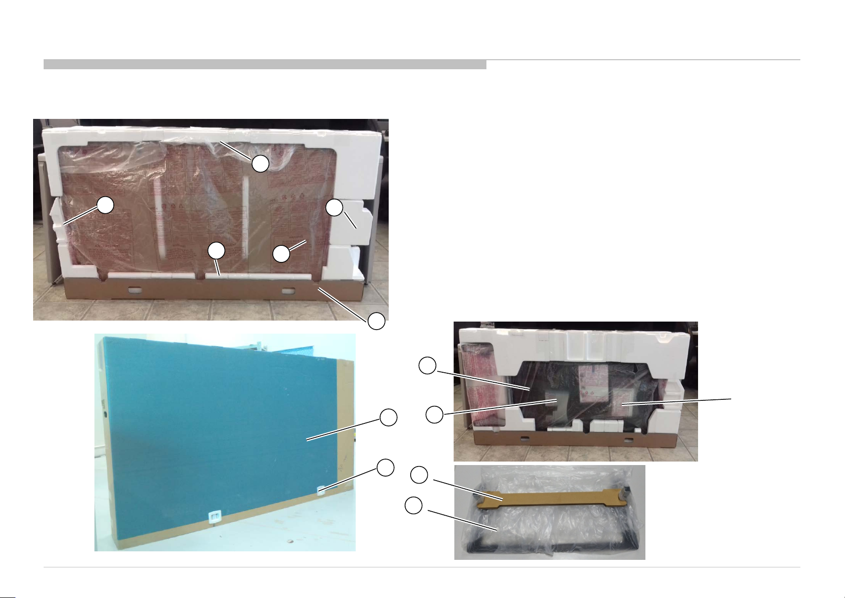
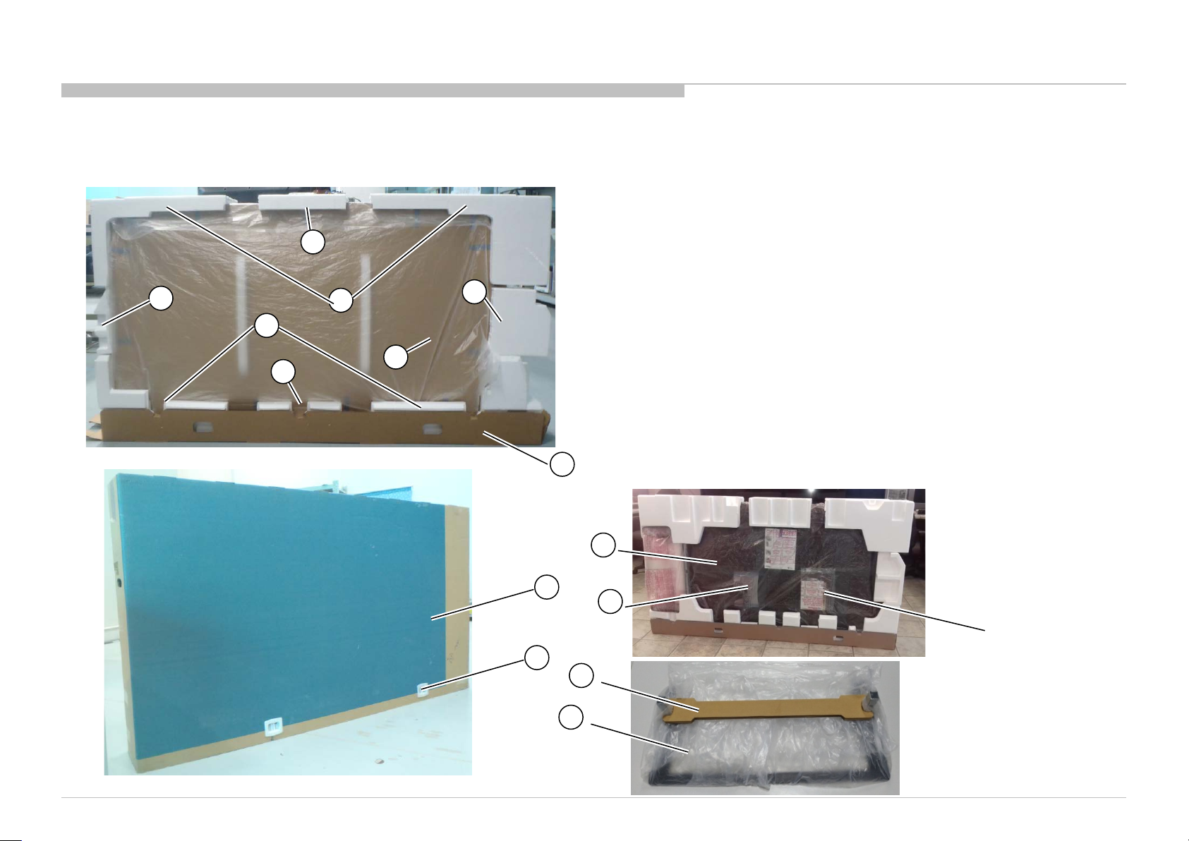
1-2-8. PACKAGE
38
39
41
40
43
42
46
47
45
ASSESSORY BAG
44
REF.NO.
PART No.
DESCRIPTION
MARK
38
4
-723-288-01
CUSHION, UPPER(60)
39
4
-723-289-01 CUSHION, LOWER (60)
40
4
-723-290-01 CUSHION, SIDE L (60)
41
4
-723-291-01 CUSHION, SIDE R (60)
42
4
-723-292-01 PLATE, EPE FRONT (60)
43
4
-723-547-01 CARTON, INDIVIDUAL (UC2)
For UC2
4
-723-549-01
CARTON, INDIVIDUAL
(LA1/LA8/CO1/AR4)
For
LA1/LA8/CO1/A
R4
4
-723-551-01 CARTON, INDIVIDUAL (AZ1/ME6/EA4)
For
AZ1/ME6/EA4
44
3
-674-673-22 STOPPER (A)
45
4
-723-285-01
BAG, STAND
46
4
-723-293-01
CARTON STAND SUPPORT (60MB)
47
4
-409-919-33 BAG,PROTECTION PEHD(1720*1050)
48
4
-729-987-01
SHEET, PROTECTION PE
(L180xW260xT1.01mm)
49
4
-729-990-01 CARTON TRAY (60)
48
49

16
DISASSEMBLY AND PARTS LIST
1-2. KD-60X690E/KD-60X695E/KD-60X697E/KD-60X6700E
KD-60X690E(UC2/LA1)/KD-60X695E(AR4/LA8)/KD-60X697E(CO1)/KD-60X6700E(AZ1/ME6/EA4)
1-2-9. OTHER PART
PART No.
DESCRIPTION
MARK
1-493-312-11
REMOTE COMMANDER (RMT
-TX300U)
For UC2/LA1
1-493-313-11
REMOTE COMMANDER (RMT
-TX300B)
For AR4/CO1/LA8
1-493-314-11
REMOTE COMMANDER (RMT
-TX300E)-AZ1
For AZ1
1-493-315-11
REMOTE COMMANDER (RMT
-TX300P)-ME6/EA4
For ME6/EA4
1-853-643-21
CARBON ZINC DRY BATTERY(R03)
DISASSEMBLY AND PARTS LIST
1-3. KD-70X690E/KD-70X6700E
KD-70X690E(UC2/LA1)/KD-70X6700E(AZ1/ME6/EA4)
17
4-723-296-01 SCREW, +PSW M5X12
7-682-961-09 SCREW, +PSW M4x8 W8
4-729-979-01 SCREW,F,CROSS,T.T-3*6,BLK-ZN.
1-3-1. STAND BLOCK
1-3-2. STAND COVER ASSY AND ST AND BASE ASSY AND NE CK
1
REF.NO.
PART No.
DESCRIPTION
MARK
1
4
-723-281-01
STAND, NECK
2
4
-723-280-01
STAND, COVER
3
4
-723-282-01
STAND, BRACKET L
4
4
-723-283-01
STAND, BRACKET R
5
4
-723-284-01
STAND, BRACKET FRONT
2
3
4
5
DISASSEMBLY AND PARTS LIST
18
KD-70X690E(UC2/LA1)/KD-70X6700E(AZ1/ME6/EA4)
1-3. KD-70X690E/KD-70X6700E
4-729-978-01 SCREW, +PSW M3X8 W8
4-268-126-02 SCREW,ORNAMENTAL M6X12
7-685-646-79 SCREW, +BVTP 3X8 TYPE2 IT-3
1-3-3. AC COVER AND RE AR COVER
REF.NO.
PART No.
DESCRIPTION
MARK
6
4
-725-317-01
COVER AC
7
1
-912-305-11
AC Cord(USA 2pin)
For UC2/LA1
1
-912-303-11
AC Cord(Europe 2pin)
For ME6
1
-912-301-11
AC Cord(UK 3pin)
For EA4
1
-912-302-11
AC Cord(AUS/NZ 2pin)
For AZ1
8
4
-723-306-01
COVER, REAR (UC2)
ForUC2
4
-723-307-01
COVER, REAR (LA1/EA4/ME6 )
For
LA1/EA4/ME6
4
-723-308-01
COVER, REAR (AZ1)
F
orAZ1
8
6
7
DISASSEMBLY AND PARTS LIST
19
1-3. KD-70X690E/KD-70X6700E
KD-70X690E(UC2/LA1)/KD-70X6700E(AZ1/ME6/EA4)
1-3-4. OVERALL
18
12
24
REF.NO.
PART No.
DESCRIPTION
MARK
9
1
-522-034-11 ANTENNA 1 (W)
10
1
-522-032-11 ANTENNA 2 (B)
11
1
-897-216-11 MOUNTED PWB POWER UNIT
12
1
-897-215-11 MOUNTED PWB A
For
UC2
1
-897-206-11 MOUNTED PWB A
For ZA1/EA4/ME6
1
-897-218-11 MOUNTED PWB A
For LA1
13
1
-897-212-11 MOUNTED PWB H
14
1
-897-213-11 MOUNTED PWB KEY
15
1
-897-207-11 MOUNTED PWB WF
16
1
-910-112-67 CONNECTOR ASSY 15P (MB-PSU)
17
1
-910-112-68 CONNECTOR ASSY (MB-SPK 1)
18
1
-910-112-69 CONNECTOR ASSY (MB-SPK 2)
19
1
-910-112-64 LVDS CABLE 41P (MB-Panel)
20
1
-910-112-65 CONNECTOR ASSY 10P (MB-IR)
21
1
-910-112-66 CONNECTOR ASSY 6P (MB-key)
22
1
-910-112-71 CONNECTOR ASSY (PSU-Panel)
23
1
-910-112-70 CONNECTOR ASSY (MB-WIFI)
24
1
-859-242-11 SPEAKER 12W
25
4
-723-312-01 SHEET, INSULATION
26
4
-723-287-01
DECO
27
4
-723-309-01 BRACKET, VESA
28
4
-723-310-01 BRACKET, BOTTOM
29
4
-723-297-01 BRACKET, SIDE IO
30
4
-723-311-01 COVER, BOTTOM
31
4
-723-294-01 CLAMP, CABLE
32
4
-729-986-01 NWF 145*8*0.35mm
2
-990-421-41
SCREW(PSW)(M3X6)
4
-729-978-01
SCREW, +PSW M3X8 W8
4
-459-864-01
SCREW, +PWTP2 4X10
28
13
10
27
17
9
15
14
21
16
20
19
26
29
31
11
30
22
23
25
32
DISASSEMBLY AND PARTS LIST
20
1-3. KD-70X690E/KD-70X6700E
KD-70X690E(UC2/LA1)/KD-70X6700E(AZ1/ME6/EA4)
A BOARD
33
REF.NO.
PART No.
DESCRIPTION
MARK
33
8
-594-302-70
TUNER MODULE SUT
-RA243ZP
For
UC2/LA1
8
-594-328-10
TUNER MODULE SUT
-DE251ZP
For AZ1/EA4/ME6
1-3-5. TUNER MODULE
For AZ1/EA4/ME6
For UC2/LA1

21
DISASSEMBLY AND PARTS LIST
1-3. KD-70X690E/KD-70X6700E
KD-70X690E(UC2/LA1)/KD-70X6700E(AZ1/ME6/EA4)
1-3-6. LCM
34
35
36
REF.NO. PART No. DESCRIPTION
MARK
34
1-812-369-11 LCM ASSY (70) (S700DUC-1)
35
4-724-144-01 BEZEL, FRONT
36
4-729-984-01 FC BTM BRACKET (70)
1-3-7. LCM (W/O BEZEL)
4
-729-980-01
SCREW,A,M2.5,L5
4
-729-981-01
SCREW(B)/M2.5*L10
22
DISASSEMBLY AND PARTS LIST
1-3. KD-70X690E/KD-70X6700E
KD-70X690E(UC2/LA1)/KD-70X6700E(AZ1/ME6/EA4)
1-3-8. PACKAGE
38
41
44
ASSESSORY BAG
43
47
48
42
46
45
37
39
40
REF.NO.
PART No.
DESCRIPTION MARK
37
38
4
-723-314-01
4
-723-313-01
CUSHION, UPPER CENTER
CUSHION, UPPER
39
4
-723-315-01 CUSHION, LOWER
40
41
4
-723-316-01
4
-723-317-01
CUSHION, LOWER CENTER
CUSHION, SIDE L
42
4
-723-318-01 CUSHION, SIDE R
43
4
-723-319-01 PLATE, EPE FRONT (70)
44
4
-723-546-01 CARTON, INDIVIDUAL (UC2)
For UC2
4
-723-548-01 CARTON, INDIVIDUAL (LA1)
ForLA1
4
-723-550-01 CARTON, INDIVIDUAL (AZ1/ME6/EA4)
For AZ1/EA4/ME6
45
3
-674-673-22 STOPPER (A)
46
4
-723-285-01 BAG, STAND
47
4
-723-293-01 CARTON STAND SUPPORT (60MB)
48
4
-409-920-33 BAG, PROTECTION PEHD(1950x1200)
49
4
-729-987-01
SHEET, PROTECTION PE
(L180xW260xT1.01mm)
50
4
-729-991-01 CARTON TRAY (70)
49
50
Loading...