


Technical Instructions
Document No. 155-517P25
July 9, 2007
SQM5…
Reversing Actuators
ISO 9000 and 14000
REGISTERED FIRM
¤
EA0511R1
Description
Features
SQM5... reversing actuators are used for the positioning of flow control valves, butterfly valves, dampers, or any application requiring rotary motion. The SQM5… actuators accommodate control input signals of 4 to 20 mA, 0 to 135 Ω, 0 to 10 Vdc, 0 to 20 mA, position proportional and floating control. The available output signals include
4 to 20 mA, 0 to 135 Ω, 0 to 10 Vdc, 0 to 20 mA, and 0 to 1000 Ω. SQM5… actuators are available with up to six internal, easily adjustable switches.
A selection of exchangeable circuit boards provide a variety of functions including auto/manual selector switch, manual forward/reverse toggle switch, zero and span adjustment, parallel or master/slave operation, split range control, input signal override, and selectable electronic linearization.
The SQM5… is engineered for precision. It is particularly well suited for applications requiring a high degree of modulating accuracy and repeatability. Drive shaft play is limited to 0.3° with a modulating accuracy of 250 repositions through 90° of travel.
The SQM5… actuator may be mounted in any position. A selection of mounting brackets and shafts provides installation flexibility and allows for the simple replacement of most competitive actuators.
•Modulating accuracy of 250 repositions through 90°
•Two limit switches, plus up to four internal auxiliary switches
•Fully closed “economy position” switch
•Drive shaft and cam drum disengagement clutches
•Auto/manual switch, manual control forward/reverse toggle switch
•UL, CSA approved 24 and 110 Vac versions
•CE approved 220 Vac versions
•Field reversible clockwise (cw) or counterclockwise (ccw) operation
•Various torque ratings and running times available
•Selection of field exchangeable single-ended and dual-ended shafts
•Mounting brackets to replace competitive actuators
Siemens Building Technologies, Inc.

Technical Instructions |
SQM5… Reversing Actuators |
Document No. 155-517P25 |
|
July 9, 2007 |
|
Features, Continued
Application
•Connections for both base and face mounting
•Low hysteresis actuator and potentiometer gearing
•Externally visible position indication
•Selection of input and output signals
•Zero and span adjustment
•Field exchangeable circuit boards and potentiometers
•Electronic damper linearization function
•Split range and selectable parallel or master/slave operation
•Adjustable input signal override function
SQM5… actuators are uniquely suited for both industrial and commercial applications. The high level of accuracy permits precise modulating control of industrial process and process heating applications, often significantly enhancing performance and product quality.
In commercial and industrial burner applications requiring high turndown and reliable ignition, the auxiliary switches can be applied to create separate positions for burner ignition and low fire. In dual fuel applications, additional switches can be used to create separate high fire, low fire and ignition positions for each fuel. The economy position switch is used to drive the actuator to the full closed position when the burner is off.
In all applications, commissioning is simplified. Shaft and cam drum disengagement clutches allow for the quick manual alignment of the actuator shaft and switch cams. The forward/reverse toggle switch in combination with the auto/manual selector switch provides direct manual control.
Page 2 |
Siemens Building Technologies, Inc. |

SQM5… Reversing Actuators |
Technical Instructions |
|
Document No. 155-517P25 |
|
July 9, 2007 |
Table Of Contents |
Application |
Page 2 |
|
||
|
Product Numbers |
|
|
Product numbers for pre-assembled UL/CSA/CE-approved |
|
|
actuators, Table 1 |
Page 4 |
|
Product numbers for accessories, Table 2 |
Page 5 |
|
SQM5… Product Number Identification Legend |
Page 6 |
|
Installation and Operating Instructions |
|
|
Shaft Installation |
Page 7 |
|
Rotational Direction Verification |
Page 8 |
|
Actuator Mounting |
Page 8 |
|
Switch Adjustment |
Page 8 |
|
Shaft Adjustment |
Page 9 |
|
Cam Drum Adjustment |
Page 9 |
|
Wiring |
|
|
Electrical Connection |
Page 9 |
|
Grounding |
Page 9 |
|
Wiring Connections |
|
|
AGA56.1… circuit boards |
Page 10 |
|
AGA56.41/42/43… circuit boards |
Page 11 |
|
AGA56.9… circuit boards |
Page 13 |
|
Commissioning |
|
|
Modulation Adjustment |
Page 15 |
|
Zero Adjustment |
Page 15 |
|
Span Adjustment |
Page 15 |
|
Cover Installation |
Page 16 |
|
Features |
|
|
SQM5x.xxxxxZx actuators |
Page 16 |
|
SQM5x.xxxxxGx actuators |
Page 18 |
|
SQM5x.xxxxxHx actuators |
Page 18 |
|
SQM5x.xxxxxKx actuators |
Page 18 |
|
SQM5x.xxxxxAx actuators |
Page 18 |
|
Service Guide |
|
|
Reversing Rotational Direction |
Page 18 |
|
Shaft Installation |
Page 20 |
|
Circuit Board Installation |
Page 20 |
|
AGA56.41/42/43… |
Page 20 |
|
AGA56.9A |
Page 22 |
|
AGA56.1A97 |
Page 24 |
|
Potentiometer Removal/Installation |
Page 25 |
|
Specification Data |
Page 26 |
|
Dimensions |
Page 29 |
Siemens Building Technologies, Inc. |
Page 3 |

Technical Instructions |
SQM5… Reversing Actuators |
Document No. 155-517P25 |
|
July 9, 2007 |
|
Product Numbers |
|
|
Table 1. Product Numbers for Pre-assembled Actuators. |
||||||||
|
|
|
|
|
|
|
|
|
|
|
|
|
Torque1 |
Running |
|
Rotation direction |
Input Control Signals3 |
|
Product Number |
|
|||
|
|
Time 2 |
|
Line Voltage |
mA20-4 |
135-0Ω |
Vdc10-0 |
|
|
|
|
|
[lb-in] |
90°@ 60 |
|
|
|
|
|
|
110 V |
220 V |
24 V |
|
|
Hzsec |
|
|
|
|
|
|
|
|
|
|
|
|
|
|
|
|
|
|
|
|
|
|
90 |
8 |
|
ccw |
x |
x |
|
|
SQM50.261R1G3 |
|
|
|
90 |
8 |
|
cw |
x |
x |
|
|
SQM50.261R1G3R |
|
|
|
90 |
8 |
|
ccw |
x |
|
|
|
SQM50.264R1A |
SQM50.264R2A |
|
|
90 |
8 |
|
cw |
x |
|
|
|
SQM50.264R1A0R |
|
|
|
90 |
8 |
|
ccw |
x |
|
|
|
SQM50.264R1A3 |
|
|
|
90 |
8 |
|
cw |
x |
x |
|
|
SQM50.264R1G3R |
|
|
|
90 |
8 |
|
ccw |
x |
x |
|
|
SQM50.264R1G4 |
|
|
|
140 |
12 |
|
ccw |
x |
x |
|
|
SQM50.361R1G3 |
|
|
|
140 |
12 |
|
cw |
x |
x |
|
|
SQM50.361R1G3R |
|
|
|
140 |
12 |
|
ccw |
x |
x |
|
|
SQM50.361R1G7 |
|
|
|
140 |
12 |
|
ccw |
x |
x |
|
|
SQM50.364R1G3 |
|
|
|
140 |
12 |
|
cw |
x |
x |
|
|
SQM50.364R1G3R |
|
|
|
140 |
25 |
|
ccw |
x |
|
|
|
SQM50.461R1A |
|
|
|
140 |
25 |
|
ccw |
x |
|
|
|
SQM50.461R1A3 |
|
|
|
140 |
25 |
|
ccw |
x |
x |
|
|
SQM50.461R1G3 |
|
|
|
140 |
25 |
|
cw |
x |
x |
|
|
SQM50.461R1G3R |
|
|
|
140 |
25 |
|
ccw |
x |
|
x |
|
SQM50.461R1H3 |
|
|
|
140 |
25 |
|
ccw |
x |
x |
x |
x |
SQM50.461R1Z3 |
|
|
|
140 |
25 |
|
ccw |
x |
x |
x |
x |
SQM50.461R1Z7 |
|
|
|
140 |
25 |
|
ccw |
x |
|
|
|
SQM50.464R1A |
|
SQM50.464R8A |
|
140 |
25 |
|
cw |
x |
|
|
|
SQM50.464R1A0R |
|
|
|
140 |
25 |
|
ccw |
x |
|
|
|
SQM50.464R1A3 |
|
|
|
140 |
25 |
|
cw |
x |
|
|
|
SQM50.464R1A3R |
|
|
|
140 |
25 |
|
ccw |
x |
x |
|
|
SQM50.464R1G3 |
|
SQM50.464R8G3 |
|
140 |
25 |
|
cw |
x |
x |
|
|
SQM50.464R1G3R |
SQM50.464R2G3R |
|
|
140 |
25 |
|
ccw |
x |
x |
|
|
SQM50.464R1G7 |
|
|
|
140 |
25 |
|
cw |
x |
x |
|
|
SQM50.464R1G7R |
|
|
|
140 |
25 |
|
ccw |
x |
|
x |
|
SQM50.464R1H3 |
|
SQM50.464R8H3 |
|
140 |
25 |
|
ccw |
x |
x |
x |
x |
SQM50.464R1Z3 |
SQM50.464R2Z3 |
SQM50.464R8Z3 |
|
200 |
25 |
|
ccw |
x |
|
|
|
SQM53.464R1A |
|
|
|
200 |
25 |
|
ccw |
x |
|
|
|
SQM53.464R1A3 |
|
|
|
200 |
25 |
|
ccw |
x |
x |
|
|
SQM53.464R1G3 |
|
|
|
200 |
25 |
|
ccw |
x |
x |
|
|
SQM53.464R1G7 |
|
|
|
200 |
25 |
|
cw |
x |
x |
|
|
SQM53.464R1G7R |
|
|
|
200 |
25 |
|
ccw |
x |
x |
x |
x |
SQM53.464R1Z3 |
SQM53.464R2Z3 |
|
|
200 |
25 |
|
ccw |
x |
x |
x |
x |
SQM53.467R1Z3 |
|
|
|
200 |
25 |
|
cw |
x |
x |
x |
x |
SQM53.467R1Z3R |
|
|
|
200 |
25 |
|
ccw |
x |
|
|
|
|
SQM53.467R2A3 |
|
|
310 |
37 |
|
ccw |
x |
|
|
|
SQM56.564R1A |
|
|
|
310 |
37 |
|
ccw |
x |
x |
|
|
SQM56.564R1G4 |
|
|
|
310 |
37 |
|
ccw |
x |
x |
|
|
SQM56.564R1G7 |
|
|
|
310 |
37 |
|
ccw |
x |
|
x |
|
SQM56.564R1H4 |
|
|
|
310 |
37 |
|
ccw |
x |
x |
x |
x |
SQM56.564R1Z3 |
|
|
|
400 |
50 |
|
ccw |
x |
x |
|
|
SQM56.664R1G3 |
|
|
|
400 |
50 |
|
ccw |
x |
x |
x |
x |
SQM56.664R1Z3 |
|
|
|
400 |
50 |
|
cw |
x |
|
|
|
SQM56.667R1A3R |
|
|
|
400 |
50 |
|
ccw |
x |
x |
|
|
SQM56.667R1G3 |
|
|
|
400 |
50 |
|
cw |
x |
x |
|
|
SQM56.667R1G7R |
|
|
|
400 |
50 |
|
ccw |
x |
x |
x |
x |
SQM56.667R1Z3 |
|
|
1.Torque will vary with the selection of the shaft. See Specifications.
2.Running time for 135° Æ multiply by 1.5. For 50 Hz Æ multiply by 1.2
3.SQM5x.xxxxxZx models also accept a 0 to 20 mA input signal.
Page 4 |
Siemens Building Technologies, Inc. |

SQM5… Reversing Actuators |
Technical Instructions |
|
Document No. 155-517P25 |
|
July 9, 2007 |
Table 2. Product Numbers for Accessories.
Electronic Circuit Boards |
|
|
AGA56.1A97 |
24-250 Vac (A) board for SQM5x.xxxxxAx |
|
AGA56.9A87 |
24 Vac |
(Z) board for SQM5x.xxxxxZx |
AGA56.9A17 |
110 Vac |
(Z) board for SQM5x.xxxxxZx |
AGA56.9A27 |
220 Vac |
(Z) board for SQM5x.xxxxxZx |
AGA56.41A87 |
24 Vac |
(G) board for SQM5x.xxxxxGx |
AGA56.41A17 |
110 Vac |
(G) board for SQM5x.xxxxxGx |
AGA56.41A27 |
220 Vac |
(G) board for SQM5x.xxxxxGx |
AGA56.42A87 |
24 Vac |
(H) board for SQM5x.xxxxxHx |
AGA56.42A17 |
110 Vac |
(H) board for SQM5x.xxxxxHx |
AGA56.42A27 |
220 Vac |
(H) board for SQM5x.xxxxxHx |
AGA56.43A87 |
24 Vac |
(K) board for SQM5x.xxxxxKx |
AGA56.43A17 |
110 Vac |
(K) board for SQM5x.xxxxxKx |
AGA56.43A27 |
220 Vac |
(K) board for SQM5x.xxxxxKx |
See Product Number Identification Legend, Figure 1.
Mounting Brackets & Adapters
AGA57.3 for replacement of Honeywell MOD III, IV actuators
AGA57.4 for replacement of Honeywell M640/740/940 and Barber Colman EA20/40/50/60 actuators. Directly adaptable to Eclipse butterfly valves.
ASK33.9 mounting kit for direct attachment to Siemens VKF41... butterfly valve. (Shaft AGA58.1 required)
Shafts
AGA58.1 10 mm round with key. Gear end only. AGA58.2 12 mm round with key. Gear end only. AGA58.3 9 mm square. Dual-ended.
AGA58.4 3/8 inch square. Dual-ended. AGA58.7 14 mm round with key. Gear end only. For exact shaft sizes, see Dimensions.
Crank Arm, Push Rods
338 031 Crank arm kit. Includes two crank arms for connecting the AGA58.4 shaft to a 1/2-inch damper shaft with two ball joints. (Does not include push rod.)
338 041 5/16" damper push rod, 12 inches long. 338 042 5/16" damper push rod, 15 inches long. 338 043 5/16" damper push rod, 18 inches long. 338 044 5/16" damper push rod, 24 inches long. 338 045 5/16" damper push rod, 36 inches long. 338 046 5/16" damper push rod, 48 inches long.
Potentiometers
ASZ12.803 and ASZ12.30 1000Ω, 90° ASZ12.833 and ASZ12.33 1000Ω, 135° ASZ22.803 and ASZ22.30 1000/1000Ω double potentiometer, 90°
ASZ22.833 and ASZ22.33 1000/1000Ω double potentiometer, 135°
ASZ16.703 135Ω, 90° (wire wound) ASZ16.733 135Ω, 135° (wire wound)
ASZ66.733 135Ω/135Ω, double potentiometer 135° (wire wound)
Additional potentiometer models available. See
Siemens technical data sheet 7921.
Siemens Building Technologies, Inc. |
Page 5 |
Technical Instructions |
SQM5… Reversing Actuators |
Document No. 155-517P25 |
|
July 9, 2007 |
|
Product Number Identification Legend
For actuator identification only. To select product numbers for ordering, see Table 1.
Figure 1. SQM5… Product Number Identification Legend.
|
|
SQM5 0 . 4 |
8 |
0 |
R |
1 |
Z |
3 |
R |
||||
Actuator family |
|
|
|
|
|
|
|
|
|
|
|
|
|
Torque |
in-lb @ 60 (50) Hz. |
|
|
|
|
|
|
|
|
|
|
|
|
0 |
90 for 8 (10) sec. running time |
|
|
|
|
|
|
|
|
|
|
||
0 |
140 for 12 (15), 25 (30), 37 (45) sec. |
|
|
|
|
|
|
|
|
|
|||
3 |
200 for 25 (30) sec. |
|
|
|
|
|
|
|
|
|
|
|
|
6 |
310 for 37 (45) sec. |
|
|
|
|
|
|
|
|
|
|
|
|
6 |
400 for 50 (60), 75 (90)sec. |
|
|
|
|
|
|
|
|
|
|||
Running time for 90° |
|
|
|
|
|
|
|
|
|
|
|
|
|
|
|
|
|
|
|
|
|
|
|
|
|
||
|
Not all actuator running times are |
|
|
|
|
|
|
|
|
|
|
||
|
available in each torque. |
|
|
|
|
|
|
|
|
|
|
|
|
|
Refer to table 1 |
|
|
|
|
|
|
|
|
|
|
|
|
60 Hz. |
50 Hz. |
|
|
|
|
|
|
|
|
|
|
||
2 |
8 sec. |
2 |
10 sec. |
|
|
|
|
|
|
|
|
||
3 |
12 sec. |
3 |
15 sec. |
|
|
|
|
|
|
|
|
||
4 |
25 sec. |
4 |
30 sec. |
|
|
|
|
|
|
|
|
||
5 |
37 sec. |
5 |
45 sec. |
|
|
|
|
|
|
|
|
||
6 |
50 sec. |
6 |
60 sec. |
|
|
|
|
|
|
|
|
||
Number of SPDT switches |
|
|
|
|
|
|
|
|
|
|
|
|
|
6 |
2 limit and 4 auxiliary switches |
|
|
|
|
|
|
|
|
||||
Shaft selection
0no shaft (shaft must be ordered separately)
1round 10 mm, single ended (for use with VKF41... butterfly valves)
4square 3/8 inch, dual ended
7round 14 mm, single ended
Approvals
R UL recognized, CSA certified
Operating voltage (Vac @50-60 Hz)
1110-120 Vac
2220-240 Vac
824 Vac
Internal circuit board (SQM5x.xxxxx G, H, K , Zx actuators require potentiometer ASZ…)
A AGA56.1A97 (position proportional control)
GAGA56.41A... (4 to 20 mA input)
HAGA56.42A... (0 to 135 Ohm input)
KAGA56.43A... (0 to 10 Vdc input)
Z AGA56.9... (all inputs/outputs, linearization, split ranging, override and pre-set positioning)
Potentiometer (1000 Ohm required when using SQM5x.xxxxx G, H, K, Zx actuators)
3ASZ12.30 (1000 ohm, 90°)
4ASZ12.33 (1000 Ohm, 135°)
7ASZ22.30 (1000/1000 Ohm, 90°)
8ASZ22.33 (1000/1000 Ohm, 135°) B ASZ16.703 (135 Ohm, 90°)
C ASZ16.733 (135 Ohm, 135°)
L ASZ66.733 (135/135 Ohm, 135°)
Rotational Direction (Product numbers ending without R are ccw)
R Clockwise (when facing gear end. See Figure 6 .)
Page 6 |
Siemens Building Technologies, Inc. |
SQM5… Reversing Actuators |
Technical Instructions |
|
Document No. 155-517P25 |
|
July 9, 2007 |
Installation and
Operation
Instructions
Shaft Installation
SQM5… actuators are sometimes shipped without the shaft installed. To install the selected shaft:
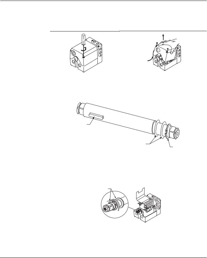
1.Loosen the two screws on the actuator cover corners. See Figure 2.
2.Lift the screws and raise the cover. See Figure 3.
EA0564R1 |
EA0568R1 |
Figure 2. |
Figure 3. |
3.Each shaft is supplied with two washers and a “C” clip. See Figure 4. Using spreading pliers, remove the “C” clip and the washers from the shaft.
KEY END
SHAFT KEY
EA0559R1
INSERT END
WASHERS ON BOTH SIDES
OF THE BEARING
C-CLIP
Figure 4.
4.Insert the “insert end” of the shaft into the “gear end” of the actuator.
5.Push the shaft until the “insert end” reaches just short of the brass bushing at the other end of the actuator.
6.Put one of the washers on the insert end of the shaft. See Figure 5.
WASHERS
EA0569R1
Figure 5.
7.Line up the “shaft key” with the key slot on the “gear end” of the actuator and slide the shaft until the “insert end” is completely through the brass bushing.
8.Place the second washer onto the “insert end” of the shaft. Using spreading pliers,
install the “C” clip.
Siemens Building Technologies, Inc. |
Page 7 |

Technical Instructions |
SQM5… Reversing Actuators |
Document No. 155-517P25 |
|
July 9, 2007 |
|
Rotational Direction
Verification
Actuator Mounting
Actuator model numbers that end with “R” are factory configured for clockwise (cw), minimum to maximum rotation when facing the gear end of the actuator, or counterclockwise (ccw) rotation when facing the other end of the actuator. The gear end of the actuator is the side opposite of the visual position indicator.
To field reverse the direction of rotation, see Service Guide, “Reversing Rotational Direction”.
SQM5… actuators can be mounted in any orientation using the four 1/4"-20 UNC tapped holes located on the bottom corners of the actuator base. Optional base mounting brackets are available. See Table 2.
SQM5… actuators can also be face mounted using self tapping screws in combination with the various holes on the face of the actuator gear end.
|
ACTUATOR |
|
SWITCH CAM I |
|
|
|
|
||||||
|
POSITION SCALE |
SET AT MAXIMUM |
|
|
|
ACTUATOR POSITION |
|||||||
|
|
|
|
|
|
|
|
|
|
DIAL POINTER |
INDICATING DIAL |
||
ACTUATOR POSITION |
|
|
SWITCH CAM II |
||||||||||
|
SET AT ZERO ("ECONOMY") CAM DRUM |
|
|
|
|
||||||||
INDICATING POINTER |
|
|
|
|
SWITCH CAM III |
|
ASZ... (1000 Ohm) |
|
|
||||
|
|
|
|
|
|
|
|
|
|||||
|
|
|
|
|
|
SET AT MINIMUM |
FEEDBACK POTENTIOMETER |
|
|
||||
|
|
|
|
|
|
|
|
|
|
|
|
|
|
CAM DRUM |
10 |
50 |
50 |
50 |
|
|
|
|
|||
0 |
30 |
|
|
||
RELEASE BUTTON |
30 |
30 |
|||
10 |
|||||
|
|
|
|
||
|
30 |
10 |
10 |
10 |
|
|
50 |
0 |
0 |
0 |
|
|
70 |
0 |
0 |
0 |
|
|
|
|
|
||
|
|
SINGLE SWITCH |
|
|
|
GEAR END |
|
CAM POINTER |
|
|
|
|
|
|
|
||
|
|
DOUBLE SWITCH CAM POINTER |
|
||
EA0561R3
Figure 6. Component Identification on the Cam Drum Side of the SQM5… Actuator.
Switch Adjustment
See Figure 6.
All SQM5…actuators are factory wired with Switch I (maximum), Switch II (fully closed “economy position”) and Switch III (minimum). The individual switch cams I, II, and III are factory set to 90°, 0° and 10° respectively.
NOTE: The single switch cam pointers are used together with the black scales when configured for counterclockwise (ccw) operation.
The double switch cam pointers are used together with the red scales when configured for clockwise (cw) operation.
The individual switch cams can be adjusted by hand or with the use of the tool attached to the outside of the hinged switch terminal protection lid.
Page 8 |
Siemens Building Technologies, Inc. |
SQM5… Reversing Actuators |
Technical Instructions |
|
Document No. 155-517P25 |
|
July 9, 2007 |
Switch Adjustment,
Continued
Shaft Adjustment
See Figure 6.
NOTE: If a potentiometer is installed, the adjustable range of the switches depends on the range of the potentiometer.
SQM5x.xxxxxAx actuators may be adjusted between 0° and 160°. SQM5x.xxxxxx3 actuators have a 90° potentiometer and the switches must be adjusted only between 0 and 90°.
SQM5x.xxxxxx4 actuators have a 135° potentiometer and the switches must be adjusted only between 0 and 135°.
The actuator shaft can be disengaged by pressing the silver shaft release button. The button is located above the grounding screw, under the hinged terminal protection cover, and to the right of the auto/manual switch. After pressing the shaft release button in and slightly upward, the shaft can be manually rotated. After the shaft has been manually aligned to the closed position, re-engage the shaft by pushing the shaft release button downwards.
Cam Drum Adjustment
See Figure 6.
Position Indicating Dial
Adjustment
Once the shaft has been set, the cam drum must be manually aligned by pressing and holding the black cam drum release button (see Figure 6). Rotate the cam drum until the “0” mark on the actuator position scale (left scale on the cam drum) is aligned with the gray actuator position indicating pointer.
The actual position of the SQM5… actuator is indicated by the gray actuator position indicating pointer (see Figure 6). The position is also displayed by the indicating dial through the housing’s window. Ensure that the actuator position indicating dial is aligned with the actuator position scale. If necessary, rotate the dial in the clockwise direction.
Wiring
Electrical Connection
CAUTION:
Turning the dial in the counterclockwise direction may loosen the potentiometer locking screw.
SQM5… actuators are equipped with two removable conduit connection plates located on the upper corner of the gear housing. Each plate is provided with two threaded connections for 1/2" NPSM conduit connectors. The use of flexible stranded wire is recommended.
Grounding |
CAUTION: |
|
To avoid electro-magnetic interference, the SQM5… actuators must be |
|
grounded. |
|
The ground terminal is located to the right of the auto/manual switch. |
|
Disconnect the circuit board wire marked 51 during high voltage testing. |
|
Reconnect it to the grounding terminal after the test. |
|
|
Siemens Building Technologies, Inc. |
Page 9 |
Technical Instructions |
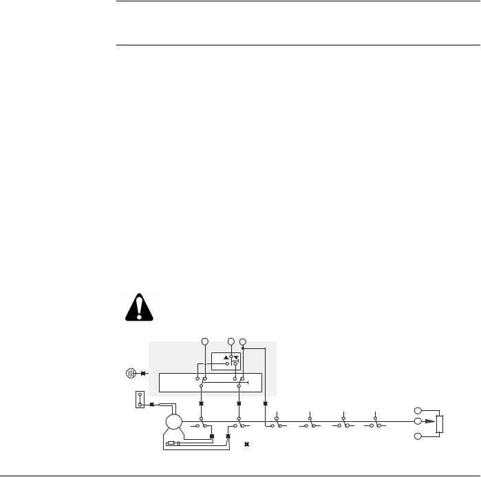
SQM5… Reversing Actuators |
Document No. 155-517P25 |
|
July 9, 2007 |
|
Wiring Connections NOTE: SQM5… actuators require a single source, single phase power supply.
AGA56.1… circuit boards. See Figures 7 and 8.
Wiring connections vary depending on which AGA56…. circuit board is installed.
Manual Operation
1.Set the AUTO/MAN switch in the MAN position.
2.Connect ground to the screw located below the shaft release button.
3.Connect neutral to the double terminal block, located on the left side of the gray switch housing.
4.Only terminal "L" must be to enable manual operation. The actuator can now be driven to the maximum position (switch cam I) or the fully closed "economy position" (switch cam II) by using the toggle switch located to the left of the AUTO/MAN switch.
Automatic Operation
1.Set the AUTO/MAN switch in the AUTO position.
2.Connect ground to the screw located below the shaft release button.
3.Connect neutral to the double terminal block located on the left side of the gray switch housing.
4.Connect line voltage to terminal A to drive the actuator in the opening direction.
5.Connect line voltage to terminal Z to drive the actuator in the closing direction.
CAUTION:
Do not power terminals A and Z simultaneously. Actuator damage will occur.
EA0555R3
AGA56.1A97 |
A |
L |
Z |
|
|
|
|
|
|
|
|
|
|
|
|
|
|
|
|
|
|
|
|
|
|
|
|
51 |
|
|
|
|
|
|
|
|
|
|
|
|
|
shown in |
|
MAN |
AUTO |
|
actuator switch |
|
|
|
|
|
|||
|
|
|
|
|
|
|
I Maximum/High fire |
|
|
|
|||
auto position |
|
|
|
|
|
|
|
II "Economy"/Fully closed |
|
|
|||
|
|
|
|
|
|
|
III Minimum/Low fire |
|
|
|
|||
|
1 |
|
2 |
13 |
|
IV...VI Auxilliary |
|
|
|
|
|||
N |
1 |
|
2 |
|
3 |
|
4 |
|
5 |
|
6 |
c |
|
I |
II |
III |
IV |
V |
VI |
|
ASZ... |
||||||
|
|
|
|
|
|
b |
|||||||
M |
|
|
|
|
|
|
|
|
|
|
|
||
11 |
21 |
12 |
22 |
13 |
23 |
14 |
24 |
15 |
25 |
16 |
26 |
|
(1000 Ohm) |
|
|
||||||||||||
|
|
21 12 |
|
|
|
|
|
|
|
|
|
a |
|
wire leads
Figure 7. Basic Functional Diagram of AGA56.1…
Page 10 |
Siemens Building Technologies, Inc. |
 Loading...