


Model FP33 User Guide
STEREO ENG MIXER . . . . . . . . . . . . . . . . . . . . . . . . . . . . . . . . . 1
©2005, Shure Incorporated |
|
Printed in U.S.A. |
27B8500 (Rev. 3) |
|
|
|
TABLE OF CONTENTS |
ENGLISH |
|
GENERAL . . . . . . . . . . . . . . . . . . . . . . . . . . . . . . . . . . . . . . |
. . . . . 1 |
FRONT PANEL CONTROLS AND INDICATORS (FIGURE 1) . . . . . |
. . . . 2 |
INPUT PANEL CONNECTORS AND CONTROLS (FIGURE 2) . . . . |
. . . . 4 |
OUTPUT PANEL CONNECTORS AND CONTROLS (FIGURE 3) . . |
. . . . 4 |
INTERNAL SWITCHES AND CONTROLS (FIGURE 4) . . . . . . . . . |
. . . . 5 |
INTERNAL SWITCHES AND CONTROLS (CONT.) . . . . . . . . . . . |
. . . . 6 |
POWERING THE FP33 MIXER . . . . . . . . . . . . . . . . . . . . . . . . . |
. . . . 6 |
BATTERY LIFE . . . . . . . . . . . . . . . . . . . . . . . . . . . . . . . . . . . |
. . . . 6 |
MIXER SETUP . . . . . . . . . . . . . . . . . . . . . . . . . . . . . . . . . . . . |
. . . . 7 |
OPERATION . . . . . . . . . . . . . . . . . . . . . . . . . . . . . . . . . . . . . |
. . . . 7 |
CONNECTING FP33 TRANSFORMER |
|
BALANCED OUTPUTS TO TELEPHONE LINES . . . . . . . . . |
. . . . 7 |
USER ADJUSTMENTS . . . . . . . . . . . . . . . . . . . . . . . . . . . . . . |
. . . . 8 |
INTERNAL MODIFIABLE FUNCTIONS . . . . . . . . . . . . . . . . . . . . |
. . . . 8 |
SPECIFICATIONS . . . . . . . . . . . . . . . . . . . . . . . . . . . . . . . . . . |
. . . . 10 |
FURNISHED ACCESSORIES . . . . . . . . . . . . . . . . . . . . . . . . . . |
. . . . 10 |
STATEMENT OF CONFORMITY . . . . . . . . . . . . . . . . . . . . . . . . |
. . . . 11 |
INFORMATION TO USER . . . . . . . . . . . . . . . . . . . . . . . . . . . . |
. . . . 11 |

ENGLISH
GENERAL
The Shure FP33 is a three-input, two-output portable stereo mixer designed for professional electronic news gathering (ENG), electronic field production (EFP), and on-loca- tion film production. The FP33 mixer sets a new standard for portable mixer performance and features. An exceptionally low-noise design makes the FP33 ideal for use with digital transmission links or digital video and audio recording media, including DAT. Lightweight, compact, and rugged, the FP33 is designed to withstand the most demanding field production conditions.
All types of dynamic and condenser microphones may be used with the FP33. The mixer provides 48 V phantom, 12 V phantom, and 12 V T (A-B) power for operating condenser microphones. It will operate for at least 8 hours on two 9 V alkaline batteries. An external 12–30 Vdc power source, such as a Shure PS20 or PS20E ac adapter, may also be used.
Features
ξExceptionally quiet design, suitable for use with DAT and other digital formats
ξExtended frequency response of 20 Hz–20 kHz
ξDynamic range greater than 100 dB
ξTransformer balanced inputs and outputs for superior rejection of RFI and electromagnetic hum
ξThree selectable mic/line inputs
ξTwo selectable mic/line outputs
ξWide range input gain controls handle hot signal levels without attenuators
ξ48 V phantom, 12 V phantom, and 12 V T (A-B) microphone power
ξPop-up pan pots
ξLink switch gangs inputs 2 and 3 to control a stereo microphone
ξSwitchable low-cut filters on each input
ξBi-color LED signal presence and peak indicator for each input
ξProfessional VU meters with selectable timed or toggled backlighting
ξDual clutched Master gain control for simultaneous or separate adjustment of output levels
ENGLISH
ξPrecision, conductive plastic, sealed rotary input potentiometers
ξBi-color LED limiter and peak indicator for each output
ξTwo linkable output peak limiters with adjustable thresholds and release times
ξSlate microphone and slate tone with selectable functions
ξIsolated two-way talk-back using Monitor In and modified Slate Mic/Tape Out jack
ξHigh tolerance 3.5 mm jacks for stereo Tape Out and Monitor In
ξ1 kHz tone oscillator
ξMix bus jack and cable to link FP33 or FP32A mixers
ξHeadphone monitor mode switch to select L, L+R (Mono), R, or Stereo
ξInternal headphone level adjustments to balance post– master audio levels and Monitor In levels at the headphone output
ξSelectable M/S decoding circuit for headphone monitor.
ξMixer/Monitor In switch (locking and momentary)
ξInternal Monitor defeat switch for split-feed headphone operation
ξHeadphone volume control
ξ1/4 in. and 3.5 mm jacks for stereo headphone outputs.
ξCustomized operation via internal DIP switches, trim pots, slide switches, and optional jumpers
ξRegulated voltage rails (ρ15 Vdc) provide exceptional headroom
ξBi-color power On/Off LED
ξBattery check switch and low battery warning LED
ξNon-polarized external power jack
ξExternal power operating range of 12 to 30 Vdc
ξSoft-touch, color coded control knobs with raised position indicators
ξMetal XLR input and output connectors
ξRugged, plated metal chassis
ξOperates for 8 hours on two 9 V alkaline batteries
ξIncludes carrying case, shoulder strap, and mix bus cable
ξDesigned and manufactured in U.S.A.
1
ENGLISH |
|
ENGLISH |
1 |
2 |
3 |
|
4 |
|
5 |
|
6 |
|
|
|
7 |
8 |
9 |
10 |
|
|
|
|
|
|
|
|
|
|
|
FP33 |
|
|
|
|
|
|
|
|
|
1 kHz |
|
LINK |
|
|
|
|
|
|
|
SLATE |
ON |
|
|
|
|
|
|
|
|
|
|
|
|
|
PEAK/LIM |
|
|
|||
|
|
|
|
|
|
|
|
|
|
|
|
|
|
|
||
L |
|
R |
L |
R |
L |
R |
|
|
|
|
BATT |
|
|
|
|
|
|
|
|
|
VU |
|
|
|
L |
|
|
||||||
|
PAN |
|
|
PAN |
PAN/BAL |
|
MIC |
|
|
|
|
|
|
|||
|
|
|
|
|
-2 -10-7-5 -3 |
0 |
+3 +5 |
|
|
L+R |
R |
|||||
|
|
|
|
|
|
|
|
|
|
0 |
|
|
|
|
||
|
|
|
|
|
|
|
|
|
L |
R |
|
|
|
L |
|
ST |
|
|
|
|
|
|
|
|
|
|
|
|
|
|
|
||
3 |
|
7 |
3 |
7 |
3 |
7 |
-20 |
|
0 |
VU |
|
+3 +5 |
|
R |
|
|
|
|
|
|
|
|
|
|
|
|
-20-10-7- -3 |
0 |
|
|
|
|
|
|
|
|
|
|
|
|
|
|
|
5 |
|
|
|
|
|
|
|
|
|
|
|
|
|
|
|
|
LIM |
|
|
|
|
|
|
0 |
|
10 |
0 |
10 |
0 |
10 |
|
|
+15 |
|
PEAK/LIM |
|
|
|
|
|
|
|
|
|
|
|
|
|
|
|
|
|
|
|
|||
|
1 |
|
|
2 |
|
3 |
|
MASTER |
dB |
|
|
|
|
MON |
|
|
|
|
|
|
|
|
|
|
|
|
|
|
|
|
|
|
|
11 |
|
|
|
12 |
|
|
13 |
14 |
15 |
16 |
|
17 |
|
18 |
19 |
|
|
|
|
|
|
|
|
|
|
|
|
|
|
|
|
|
|
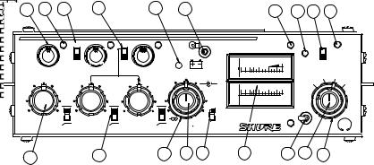
Figure 1
FRONT PANEL CONTROLS AND INDICATORS (Figure 1)
1.Pan Control: Adjusts the amount of input signal sent to the Left and Right outputs. Each Pan knob has a center detent position. To avoid accidental movement of the knob once it has been set, it may be pushed in flush with the front panel.
Note: Pan Control 3 becomes a Left/Right Balance Control when the LINK switch is activated (see the LINK switch description for details).
2.Input Level Bi-Color LED: Glows green to indicate the presence and relative level of an input signal. Also glows red if the input signal reaches 6 dB below the clipping (distortion) level. To program this LED so that it functions only as a clipping level indicator, open the battery compartment and move DIP Switch 10 to the Off position.
3.1 kHz Tone Oscillator Switch: Use the 1 kHz tone to send a reference signal to any device connected to an FP33 output. The 1 kHz tone mutes all inputs. The tone level can be adjusted with the Master control.
4.Link Switch: In the LINK position (up), this switch links the gain controls of Inputs 2 and 3 so they act as a stereo pair. Input 2 is Left and Input 3 is Right. The Input 3 Gain knob adjusts the level of the stereo pair. The Input 3 Pan knob adjusts the Left/Right balance.
Note: Channel 2 Gain and Pan are disabled when the LINK switch is activated. The low-cut filters for Input 2 and Input 3 are not linked.
5.Slate Microphone: The built-in condenser microphone is activated when the Slate button is pressed. See the Slate Button section for more information.
Note: To disable both the Slate microphone and the Slate tone, set internal DIP Switches 5, 6, and 7 to Off. The Slate microphone may also be modified to act as a talk-back microphone for communications. Refer to the Internal Modifiable Functions section for details.
6.Meter Lamp/Battery Check Switch: The Meter Lamp function is activated by momentarily pushing this switch upward. This function can be internally preset for timed or toggled deactivation. See the table in the Internal Switches and Controls section for details.
The Battery Check function is activated by momentarily pushing this switch downward. The status of the two 9 V batteries is indicated on the VU meter. When the mixer is using an external dc supply and no batter-
ies, the Battery Check indicates the status of the external operating voltage. When the mixer is using 9 V batteries and an external dc supply, the Battery Check indicates the status of the higher voltage source. A low battery condition also is indicated when the Power On LED changes to red and flashes at a slower rate. For instructions on modifying the FP33 to allow only internal batteries or external power to be monitored at the VU meter, see Internal Modifiable Functions.
Note: The audio signal is not interrupted when the Battery Check switch is activated.
7.Output Peak/Limiter Bi-Color LED: Glows red for the individual Left and Right Channels when the output signal reaches a factory preset peak level of +17 dBm. This peak level is user-adjustable from 0 dBm to +17 dBm. (See the Peak LED Adjustment instructions.) If the Limiter is switched on, each LED glows green to indicate Limiter operation. The LED will still glow red if the preset peak level is reached before the Limiter activation point is reached.
8.Slate Button: Activates a 400 Hz Slate Tone for one second and also activates the Slate Microphone. The Slate Microphone remains on while the button is depressed. The Slate signal (Tone and Mic) appears at the Left and Right outputs to identify the beginning of a take. If desired, the Slate features can be modified as follows: disable the Slate Tone; insert the Slate signal pre-Master control; or insert the Slate signal postMaster control. See the Internal DIP Switches table for instructions.
Note: To disable both the Slate microphone and the Slate tone, set internal DIP Switches 5, 6, and 7 to Off.
9.Power On/Off Switch: Turns the mixer on and off. The mixer is on when this switch is in the “up” position.
10.Power On LED: Monitors the higher of the internal or external voltage sources. Flashes green to indicate power is on and voltage is greater than 12 Vdc. Flashes red and slower to indicate low power (12 Vdc or less).
When this LED monitors the internal battery level, it glows red typically when 30 minutes of battery power remain. Refer to the Internal Battery Life section. For instructions on modifying the FP33 to allow only internal batteries or external power to be monitored at
2

ENGLISH
the VU meter, refer to the Internal Modifiable Functions section.
11.Input Gain Control: Adjusts the gain level of each input channel. Rotating the knob counterclockwise reduces the gain and raises the input clipping point. Use a low control setting to handle “hotter” input signals without distortion. With the FP33 input circuit, microphones with a “hot” output may be used without an inline pad (attenuator). For best performance, adjust each Input Gain control so the associated Input Level LED illuminates red only on the loudest signal peaks.
12.Input Low-Cut Filter Switch: Provides low-frequen- cy roll-off to reduce wind noise and rumble. When using the filter, the frequency response is down 6 dB at 150 Hz. The roll-off slope is 6 dB per octave.
13.Master Gain—Right Channel Output: The outer ring controls the Right channel output gain. The dualclutched control lets the Right and Left outputs be adjusted individually. Set it to “0 dB” for unity gain.
14.Master Gain—Left Channel Output: The inner knob controls the Left channel output gain. The dualclutched control lets the Right and Left outputs be adjusted individually. Set it to “0 dB” for unity gain.
Note: The 1 kHz tone oscillator level is set by the Master Level controls. To calibrate other devices, adjust the Master Level controls for a 0 VU response.
15.Output Peak Limiter Switch: Activates two fast-act- ing, peak-responding limiters, one for each output channel. Limiters help prevent overload distortion from unexpected loud input signals. The limiter activation is indicated by the Output Peak/Limiter LEDs, which illuminate green.
The limiters may be changed to: operate independently; be linked as a stereo pair; activate at thresholds from 0 dBm to +15 dBm; and have release time constants of 0.1 second or 1 second. See the Internal
ENGLISH
DIP Switches and Limiter Threshold Adjustment for instructions.
16.Left/Right Channel Output Level Meters: 0 VU is preset at a +4 dBm output level. This may be recalibrated for each meter by an internal trim potentiometer. See the VU Meter Adjustment paragraph for instructions.
Note: Mechanical meters are used because LCD meters do not operate properly in cold weather; fluorescent meters drain batteries too quickly; and LED meters are difficult to see in sunlight.
17.Monitor Input Switch: In the center position, this switch sends the post-master audio to the headphone output. In the left (locking ) or right (momentary) position, it sends the audio signal from the Monitor In jack to the headphone output.
18.Headphone Gain Control (Inner Knob): Adjusts the headphone volume level.
WARNING: The headphone circuit is capable of producing high volume levels that can damage the user’s hearing. Make sure the headphone volume setting is low (fully CCW) before putting on the headphones.
19.Headphone Monitor Mode Switch (Outer Ring):
The user can monitor the FP33 output as: Stereo; Right channel only; Mono (Left + Right); or Left channel only.
Note: This switch also affects the Monitor In signal. When using a stereo MS microphone, such as the Shure VP88, the user may wish to pass the mic signal through the FP33 as separate Mid and Side signals, yet hear decoded stereo in the headphones. Using the Headphone MS Matrix, the user can monitor the FP33 output as: Discrete (Mid and Side); Side only, Stereo (decoded MS), or Mono (Mid only). Refer to the Internal DIP Switch table for instructions on activating the Headphone MS Matrix.
3
 Loading...