


HM210BD(EN).fm Page 1 Thursday, March 2, 2006 6:07 PM
VIDEO CASSETTE RECORDER
31B-250 31B-254 (PDC)
31B-450 31B-454 (PDC)
PAL
Owner’s Manual
Table of Contents |
|
Safety Information ............................................................................................................................................. |
2 |
Before Using This Product ................................................................................................................................ |
3 |
Installation ......................................................................................................................................................... |
5 |
Basic Operation ................................................................................................................................................ |
9 |
Advanced Operations ..................................................................................................................................... |
10 |
Maintenance ................................................................................................................................................... |
14 |
Troubleshooting Guide ................................................................................................................................... |
15 |
Specifications .................................................................................................................................................. |
15 |
Declaration of Conformity ............................................................................................................................... |
16 |
Features
•Automatic Operations
•On Screen Display
•Auto Repeat Playback
•Picture Select
•One Touch Recording
•Parental Lock
•Auto Return
Supplied Accessories
•Remote control
•Two R6 batteries
•RF cable
•Quick setup guide
Important Copyright Information
Unauthorised recording or use of broadcast television programming, video tape, film or other copyrighted material may violate applicable copyright laws. We do not take responsibility for the unauthorised duplication, use, or other acts which infringe upon the rights of copyright owners.
A Note About Recycling
This product’s packaging materials are recyclable and can be reused. Please dispose of any materials in accordance with your local recycling regulations.
Printed in China
•Timer Recording
•Auto Head Cleaner
•NTSC Playback
•Auto Clock Setting (31B-254/31B-454)
•PDC (31B-254/31B-454)
•Quick-Find (31B-450/31B-454)
•Index/Time Search (31B-450/31B-454)
This product consists of materials which can be recycled and reused if disassembled by a
specialised company. Batteries should never be thrown away or
incinerated but disposed of in accordance with your local regulations concerning chemical
wastes.
Model/Serial Number
This appliance has a serial number located on the rear panel. Please note down the model number and serial number and retain the information for your records.
Model number:
Serial number:
1VMN22718
HM210BD***** EN
HM210BD(EN).fm Page 2 Thursday, March 2, 2006 6:07 PM
Safety Information
WARNING:
•Live parts inside. Do not remove any screws.
•To avoid fire or electric shock, do not expose this unit to rain or moisture.
•Dangerous voltage inside
Connection to Power
Before Switching on make sure that the voltage of your electricity supply is the same as that indicated on the rating plate.
Mains Cord
Precautions
•Use only cassettes with the VHS mark with this VCR.
•Do not attempt to open the cabinet. There are no parts you can service inside. Refer all servicing to qualified service personnel.
•Slots and openings in the cabinet and the sides or bottom are provided for ventilation. To ensure reliable operation and to protect the unit from overheating, these openings must not be blocked or covered.
•Avoid installation in enclosed spaces such as bookcases unless proper ventilation is provided.
•Keep the unit away from radiators and other heat sources.
•Avoid use near strong magnetic fields.
•Do not push objects of any kind into the VCR through the cabinet slots or openings as they could touch electrically live parts or short circuit parts resulting in a fire or electric shock.
•Never spill liquid on this unit. If liquid is spilled and penetrates into the unit, consult qualified service personnel.
•Use this unit in a horizontal (flat) position only.
•Before attempting to operate the unit, make sure that the Timer Recording mode is “OFF”.
•This product is in Stand-by mode when it turns off while the power cord is connected.
•Disconnect the mains plug to shut off when find troubles or not in use.
•The mains plug shall remain readily operable.
•Read both manual instructions to ensure correct and safe installation and interconnection of the unit in multimedia systems.
•Keep the distances 20 cm around apparatus of ventilation openings.
•Do not place any combustible objects on the device (candles, etc.).
Power Supply
The main power supply is engaged when the power cord plug is plugged in a 220-240V, 50Hz, AC outlet. To operate the unit, press FUNCTION to turn on the unit. (FUNCTION indicator on the VCR comes on.)
Dew Warning
Moisture condensation may occur inside the unit when it is moved from a cold place to a warm place, after heating up a cold room, or under conditions of high humidity. Do not use the VCR for at least 2 hours until it is dry inside.
Positioning
Do not place the VCR directly on top of, or underneath, your TV set. Ensure that there is at least 20 cm between the VCR and the TV set, and that air can circulate freely through the ventilation openings of the VCR.
This appliance may be fitted with a non-rewireable plug. If it is necessary to change the fuse in a non-rewireable plug the fuse cover must be refitted. If the fuse cover is lost or damaged, the plug must not be used until a replacement available from the appliance manufacturer is obtained.
It is important that the colour of the replacement fuse cover corresponds with the rating marking on the base of the plug. If the plug has to be changed because it is not suitable for your socket, or becomes damaged, it should be cut off and an appropriate plug fitted following the wiring instructions below. The plug removed must be disposed of safely as insertion into a 13A socket is likely to cause an electrical hazard. For your own safety read the following instructions carefully before attempting to connect this unit to mains. The wires in this mains lead are coloured in accordance with the following code:
BLUE=NEUTRAL, BROWN=LIVE
Important
As the colours of the wires in the mains lead of this appliance may not correspond with the coloured markings identifying the terminals in your plug, proceed as follows:-
The wire which is coloured blue must be connected to the terminal which is marked with the letter N or coloured black. The wire which is coloured brown must be connected to the terminal which is marked with the letter L or coloured red. No connection is to be made to the earth terminal of the plug. If a 13 Amp (BS 1363) Plug is used, a 3 Amp Fuse must be fitted, or if any other type of Plug is used a 3 or 5 Amp Fuse must be fitted, either in the Plug or Adaptor, or on the Distribution Board.
Mains Supply: 220 - 240 V ~ 50 Hz - AC only
Do not make any connection to the larger pin marked with the letter “E” or by the symbol  or coloured green or green and yellow.
FUSE
BROWN (Live)
BLUE
(Neutral)
CORD GRIP
OUTER SHEATH OF THE WIRE
2 |
EN |

HM210BD(EN).fm Page 3 Thursday, March 2, 2006 6:07 PM
Before Using This Product
Description of Controls
Front Panel
1
FUNCTION CHANNEL
STANDBY
FUNCTION
TAP
E
I
N
T
I MER
AUTO RETURN REC/OTR STOP/EJECT REW |
PLAY |
F.FWD |
REC
|
|
10 9 |
|
|
8 |
7 6 |
5 |
4 |
3 2 |
1. |
Cassette compartment |
|
|
|
|
6. |
REC/OTR button |
||
2. |
F.FWD (Fast Forward) button |
|
|
|
7. |
AUTO RETURN button |
|||
3. |
PLAY button |
|
|
|
|
|
8. |
Indicator (See below.) |
|
4. |
REW (Rewind) button |
|
|
|
9. |
CHANNEL (K/L) buttons |
|||
5. |
STOP/EJECT button |
|
|
|
|
10. |
FUNCTION button |
||
Indicator |
|
|
|
|
|
|
|
|
|
|
11 |
12 |
13 |
14 |
15 |
|
|
|
|
|
Y |
NDB |
|
STA |
|
FUNCTIO
N
TAPE
I
N
T
I
MER
REC
11.STANDBY indicator
12.FUNCTION indicator
13.TAPE IN indicator
14.TIMER indicator
15.REC indicator
Rear Panel
16 |
17 |
18 |
|
AV2(DECODER) |
AV1(TV) |
AERIAL
RF OUT
20 19
16.Power cord
17.AV2 (DECODER) socket
18.AV1 (TV) socket
19.RF OUT socket
20.AERIAL socket
3 |
EN |
HM210BD(EN).fm Page 4 Thursday, March 2, 2006 6:07 PM
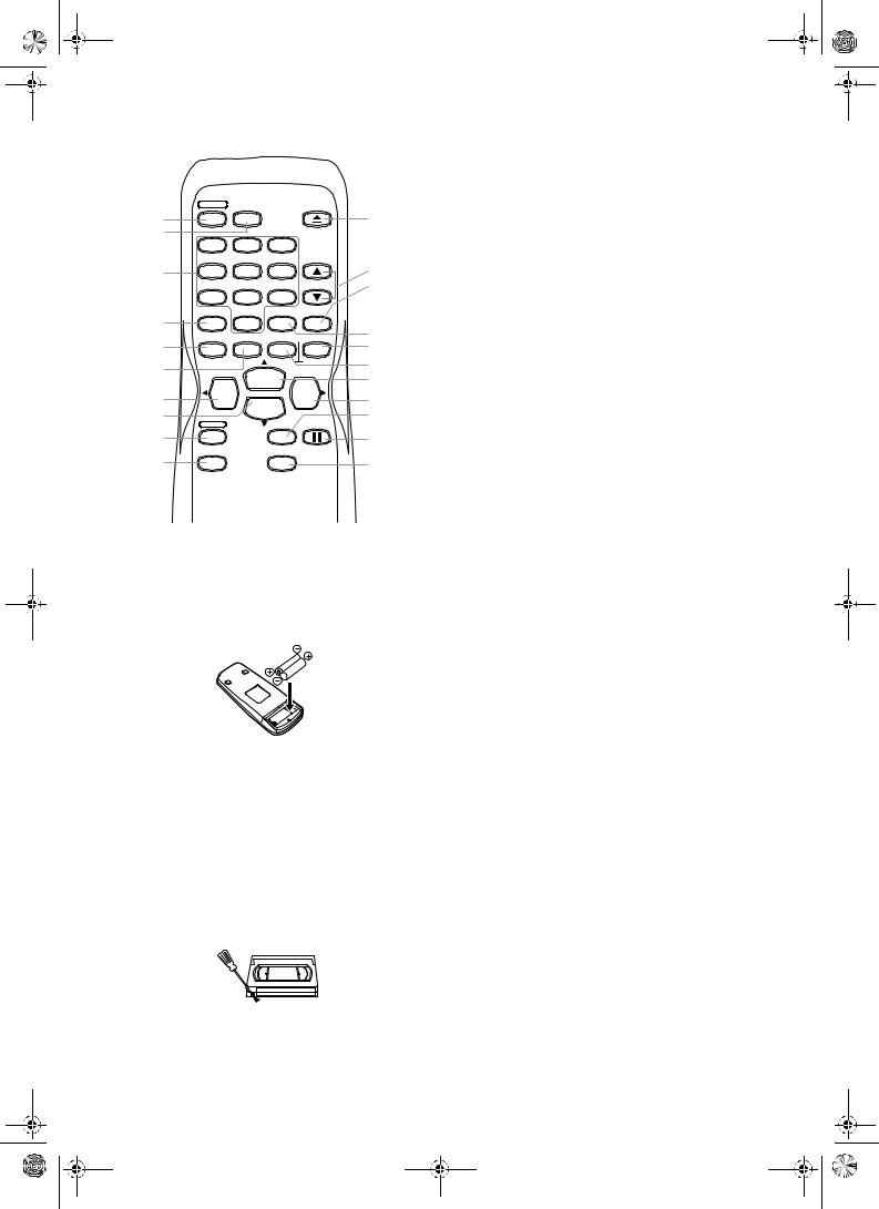
Remote Control
|
FUNCTION |
AUDIO |
|
EJECT |
|
|
|
SELECT |
|
18 |
|||
1 |
|
|
||||
|
|
|
|
|||
* |
1 |
2 |
3 |
|
|
|
|
|
|
||||
2 |
4 |
5 |
6 |
|
17 |
|
|
|
|
|
16 |
||
|
|
|
|
CHANNEL |
||
|
7 |
8 |
9 |
|
Only functions |
|
|
|
|
|
SLOW |
for 31B-450/ |
|
* |
|
|
|
31B-454 |
||
|
0 |
|
|
|||
|
|
|
* |
|||
3 |
MENU |
DISPLAY |
TAPE COUNTER |
|||
15 |
||||||
|
|
|
|
|||
4 |
|
|
RESET |
MEMORY |
14 |
|
|
|
PLAY |
|
13 |
||
5 |
REW |
|
|
F.FWD |
12 |
|
|
STOP |
|
||||
6 |
|
|
11 |
|||
REC/OTR |
|
SPEED/ |
PAUSE/STILL |
|||
|
|
SYSTEM |
|
|||
7 |
|
|
10 |
|||
|
|
|
|
|||
8 |
QUICK-FIND |
|
SEARCH MODE |
9 |
||
|
|
|
|
|||
Only functions |
|
|
|
|
Only functions |
|
for 31B-450/ |
|
|
|
|
for 31B-450/ |
|
31B-454 |
|
|
|
|
31B-454 |
|
1.FUNCTION button
2.number buttons
3.MENU button
4.DISPLAY button
5.REW/s button
6.STOP/L button
7.REC/OTR button
8.QUICK-FIND button
(Only functions for 31B-450/31B-454)
9.SEARCH MODE button
(Only functions for 31B-450/31B-454)
10.PAUSE/STILL F button
11.SPEED/SYSTEM button
(Only the function of SPEED is available for this VCR.)
12.F.FWD/B button
13.PLAY/K button
14.TAPE COUNTER RESET button
15.TAPE COUNTER MEMORY button
16.SLOW button
(Only functions for 31B-450/31B-454)
17.CHANNEL (K/L) buttons
18.EJECT A button
* These buttons do not function for this VCR.
To insert the batteries:
Install two R6 batteries matching the polarity indicated inside the battery compartment.
Caution
Do not mix old and new batteries. (Also never mix alkaline batteries with manganese batteries.)
Video Cassette Tape
This VCR will operate with any cassette that bears the VHS mark. For best results, we recommend the use of high-quality tapes. Do not use poor quality or damaged tapes.
You can prevent accidental erasing of a recording by breaking off the erase-prevention tab on the back edge of the cassette. If you decide to record on the tape again, cover the hole with plastic tape.
Two Different Tape Speeds
Before recording, select the tape speed : SP mode (Standard Play) or LP mode (Long Play). The table below shows the maximum recording/playback time using E-60, E-120, E-180 or E-240 tapes in each mode.
Tape Type |
Recording/Playback Time |
||
|
Tape Speed |
SP Mode |
LP Mode |
|
E-60 |
1 hour |
2 hours |
|
E-120 |
2 hours |
4 hours |
|
E-180 |
3 hours |
6 hours |
|
E-240 |
4 hours |
8 hours |
TV Colour System
Different countries use different television colour systems. Tapes recorded in the PAL or NTSC system can be played back on this unit. Usually, the picture on the TV screen will be in black and white when you play back a tape that is recorded in a different colour system.
Tapes recorded in the NTSC system can be played back on this unit and a PAL system TV set. This feature is only available in the SP mode. When playing back such tapes, the picture may roll up or down, shrink vertically and black bars may appear both at the top and bottom of the screen. Adjust the vertical hold control on your TV, if the TV features this control.
 Tab
Tab
4 |
EN |
HM210BD(EN).fm Page 5 Thursday, March 2, 2006 6:07 PM
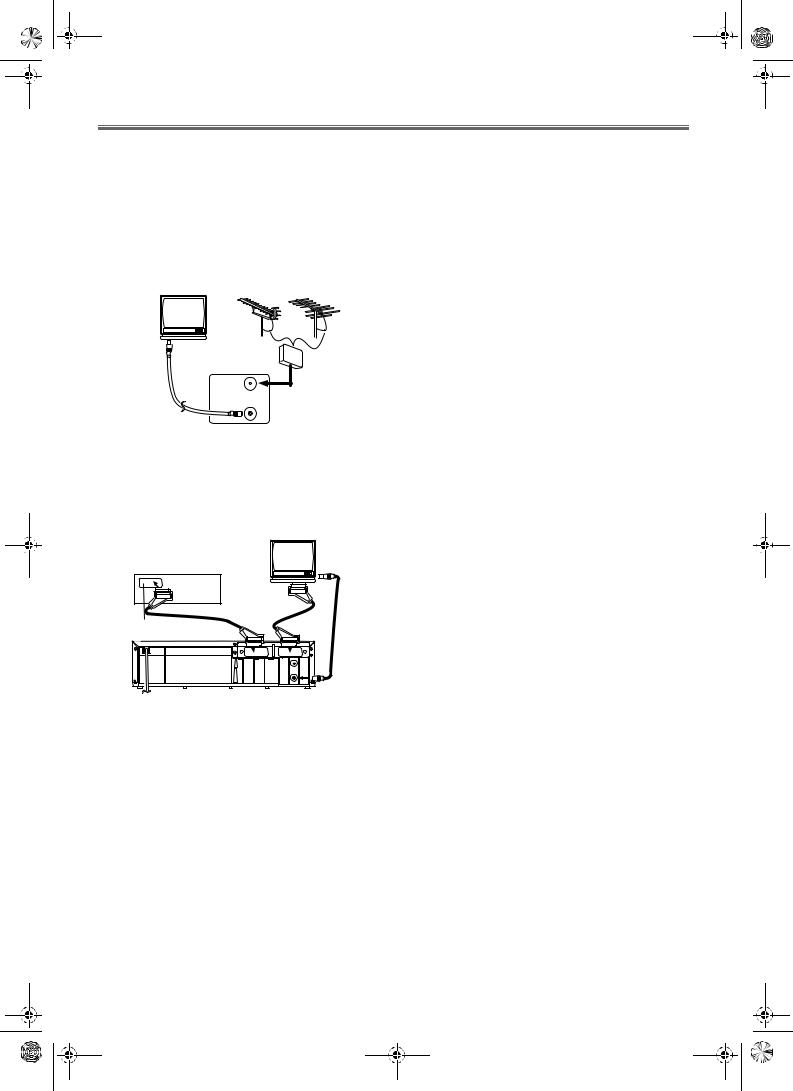
Installation
Connecting the VCR
Basic Connection
1)Disconnect the TV’s power cord from the AC outlet.
2)Disconnect the VHF/UHF TV aerial coaxial cable from the TV.
3)Connect the VHF/UHF TV aerial coaxial cable to the VCR.
4)Connect the VCR to the TV using the RF cable.
5)Plug the power cords of the VCR and TV into the AC outlets.
UHF |
VHF |
(TV) |
|
to aerial socket |
|
|
VHF/UHF |
|
MIXER |
RF cable |
to AERIAL |
AERIAL |
|
(supplied) |
|
RF OUT |
|
to RF OUT
(Back of the unit)
Other Connections
Euro Scart (AV) Sockets
Your VCR is provided with two Scart sockets which you may connect to other external devices with Scart sockets. We recommend this connection to ensure a better audio and picture quality.
|
(TV) |
to aerial |
Decoder (Not supplied) |
|
socket |
to 21-Pin |
|
|
Scart socket |
|
|
to 21-Pin Scart socket |
|
|
AV2(DECODER) |
AV1(TV) |
|
|
AERIAL |
|
|
RF OUT |
|
|
|
to RF OUT |
Euro Scart cables are obtainable at your dealer.
AV1 (TV) Connection to TV
If your TV has Scart sockets, you may connect your VCR’s AV1 (TV) scart socket to the Scart socket on the back of your TV. Please see the instruction manual for your TV.
AV2 (DECODER) Connection for Other External Devices
The second Scart socket AV2 (DECODER) is designated for other external devices, e.g. decoder, another VCR, video camera and so on.
Note: If you want to connect a TV with Scart socket to your VCR, the TV must be connected to the VCR through AV1 (TV). A connection to AV2 (DECODER) will not function correctly.
External Input Mode
To receive the signal from an external source (decoder, video camera, another VCR, etc.), connect the source to the AV2 (DECODER) socket, and press CHANNEL (K/L) or enter “002” with the number buttons. “AV2” appears on the TV screen. If you use the AV1 (TV) socket, press CHANNEL (K/L) or enter “001” with the number buttons. “AV1” appears on the TV screen.
5 |
EN |
 Loading...