


38AKS013-024 Air-Cooled Condensing Units 50/60 Hz
Installation, Start-Up and
Service Instructions
CONTENTS
Page
SAFETY CONSIDERATIONS . . . . . . . . . . . . . . . . . . . 1
INSTALLATION . . . . . . . . . . . . . . . . . . . . . . . . . . . . . 1-12
Step 1 Ð Complete Pre-Installation
Checks . . . . . . . . . . . . . . . . . . . . . . . . . . . . . . . . . . . . 1
Step 2 Ð Rig and Mount the Unit . . . . . . . . . . . . . 8
Step 3 Ð Complete Refrigerant Piping
Connections . . . . . . . . . . . . . . . . . . . . . . . . . . . . . . . 8
Step 4 Ð Install Accessories . . . . . . . . . . . . . . . . 10
Step 5 Ð Complete Electrical
Connections . . . . . . . . . . . . . . . . . . . . . . . . . . . . . . 10
PRE-START-UP . . . . . . . . . . . . . . . . . . . . . . . . . . . . . 12
System Check . . . . . . . . . . . . . . . . . . . . . . . . . . . . . . 12
Leak Test and Dehydration . . . . . . . . . . . . . . . . . . 12
Turn On Crankcase Heater . . . . . . . . . . . . . . . . . . . 12
Preliminary Charge . . . . . . . . . . . . . . . . . . . . . . . . . . 12
START-UP . . . . . . . . . . . . . . . . . . . . . . . . . . . . . . . . 13-16
Preliminary Checks . . . . . . . . . . . . . . . . . . . . . . . . . 13
Preliminary Oil Charge . . . . . . . . . . . . . . . . . . . . . . 13
Start Unit . . . . . . . . . . . . . . . . . . . . . . . . . . . . . . . . . . . 13
Adjust Refrigerant Charge . . . . . . . . . . . . . . . . . . . 13
Check Compressor Oil Level . . . . . . . . . . . . . . . . 13
Final Checks . . . . . . . . . . . . . . . . . . . . . . . . . . . . . . . . 13
OPERATING SEQUENCE . . . . . . . . . . . . . . . . . . . . 17
Cooling . . . . . . . . . . . . . . . . . . . . . . . . . . . . . . . . . . . . . 17
Heating . . . . . . . . . . . . . . . . . . . . . . . . . . . . . . . . . . . . . 17
Fan Cycling . . . . . . . . . . . . . . . . . . . . . . . . . . . . . . . . . 17
Winter Start Control . . . . . . . . . . . . . . . . . . . . . . . . . 17
SERVICE . . . . . . . . . . . . . . . . . . . . . . . . . . . . . . . . . . 17-19
Capacity Control . . . . . . . . . . . . . . . . . . . . . . . . . . . . 17
Head Pressure Control . . . . . . . . . . . . . . . . . . . . . . 17
Time GuardT II Circuit . . . . . . . . . . . . . . . . . . . . . . . 17
Winter Start Control . . . . . . . . . . . . . . . . . . . . . . . . . 18
Crankcase Heater . . . . . . . . . . . . . . . . . . . . . . . . . . . 18
Compressor Protection . . . . . . . . . . . . . . . . . . . . . . 18
High-Pressure Switches . . . . . . . . . . . . . . . . . . . . . 18
Low-Pressure Switches . . . . . . . . . . . . . . . . . . . . . 18
Outdoor Fans . . . . . . . . . . . . . . . . . . . . . . . . . . . . . . . 18
Lubrication . . . . . . . . . . . . . . . . . . . . . . . . . . . . . . . . . 18
Cleaning Coils . . . . . . . . . . . . . . . . . . . . . . . . . . . . . . 18
TROUBLESHOOTING . . . . . . . . . . . . . . . . . . . . . . 20,21
START-UP CHECKLIST . . . . . . . . . . . . . . . . CL-1,CL-2
SAFETY CONSIDERATIONS
Installing, starting up, and servicing air-conditioning equipment can be hazardous due to system pressures, electrical components, and equipment location (roofs, elevated structures, etc.).
Only trained, quali®ed installers and service mechanics should install, start-up, and service this equipment (Fig. 1).
Untrained personnel can perform basic maintenance functions such as cleaning coils. All other operations should be performed by trained service personnel.
When working on the equipment, observe precautions in the literature and on tags, stickers, and labels attached to the equipment.
Follow all safety codes. Wear safety glasses and work gloves. Keep quenching cloth and ®re extinguisher nearby when brazing. Use care in handling, rigging, and setting bulky equipment.
ELECTRIC SHOCK HAZARD
Separate power sources (main and control power circuits) are used for these units. Be sure both main and control power circuits are disconnected before servicing.
INSTALLATION
Step 1 Ð Complete Pre-Installation Checks
UNCRATE UNIT Ð Remove unit packaging except for the top skid assembly, which should be left in place until after the unit is rigged into its ®nal location.
INSPECT SHIPMENT Ð File claim with shipping company if shipment is damaged or incomplete.
CONSIDER SYSTEM REQUIREMENTS
·Consult local building codes and National Electrical Code (NEC, U.S.A.) for special installation requirements.
·Allow sufficient space for air¯ow clearance, wiring, refrigerant piping, and servicing unit. See Fig. 1. See Fig. 2 for unit component locations.
·Locate unit so that outdoor coil (condenser) air¯ow is unrestricted on all sides and above.
·Unit may be mounted on a level pad directly on the base channels or mounted on raised pads at support points. See
Tables 1A-1D for unit operating weights. See Table 2 for weight distribution based on recommended support points.
NOTE: If vibration isolators are required for a particular installation, use the data in Table 2 to make the proper selection.
Manufacturer reserves the right to discontinue, or change at any time, speci®cations or designs without notice and without incurring obligations.
Book |
1 |
4 |
|
PC 111 |
Catalog No. 563-701 |
Printed in U.S.A. |
Form 38AKS-3SI |
Pg 1 |
9-98 |
Replaces: 38AKS-2SI |
Tab |
3a |
2a |
|
|
|
|
|
|
|
|
|
|
|
|
|
|
|
|
|
|
|

NOTE: Service areas Ð Allow 3 ft (914 mm) on both sides and 2 ft (610 mm) on both ends of unit for servicing.
2
Fig. 1 Ð Dimensions

1 |
|
|
|
2 |
|
|
|
|
|
3 |
4 |
|
|
5 |
6 |
7 |
||||||||||||||||||||||||||||||||||||||||||||||||||||||||||
|
|
|
|
|
|
|
|
|
|
|
|
|
|
|
|
|
|
|
|
|
|
|
|
|
|
|
|
|
|
|
|
|
|
|
|
|
|
|
|
|
|
|
|
|
|
|
|
|
|
|
|
|
|
|
|
|
|
|
|
|
|
|
|
|
|
|
|
|
|
|
|
|
|
|
|
|
|
|
|
|
|
|
|
|
|
|
|
|
|
|
|
|
|
|
|
|
|
|
|
|
|
|
|
|
|
|
|
|
|
|
|
|
|
|
|
|
|
|
|
|
|
|
|
|
|
|
|
|
|
|
|
|
|
|
|
|
|
|
|
|
|
|
|
|
|
|
|
|
|
|
|
|
|
|
|
|
|
|
|
|
|
|
|
|
|
|
|
|
|
|
|
|
|
|
|
|
|
|
|
|
|
|
|
|
|
|
|
|
|
|
|
|
|
|
|
|
|
|
|
|
|
|
|
|
|
|
|
|
|
|
|
|
|
|
|
|
|
|
|
|
|
|
|
|
|
|
|
|
|
|
|
|
|
|
|
|
|
|
|
|
|
|
|
|
|
|
|
|
|
|
|
|
|
|
|
|
|
|
|
|
|
|
|
|
|
|
|
|
|
|
|
|
|
|
|
|
|
|
|
|
|
|
|
|
|
|
|
|
|
|
|
|
|
|
|
|
|
|
|
|
|
|
|
|
|
|
|
|
|
|
|
|
|
|
|
|
|
|
|
|
|
|
|
|
|
|
|
|
|
|
|
|
|
|
|
|
|
|
|
|
|
|
|
|
|
|
|
|
|
|
|
|
|
|
|
|
|
|
|
|
|
|
|
|
|
|
|
|
|
|
|
|
|
|
|
|
|
|
|
|
|
|
|
|
|
|
|
|
|
|
|
|
|
|
|
|
|
|
|
|
|
|
|
|
|
|
|
|
|
|
|
|
|
|
|
|
|
|
|
|
|
|
|
|
|
|
|
|
|
|
|
|
|
|
|
|
|
|
|
|
|
|
|
|
|
|
|
|
|
|
|
|
|
|
|
|
|
|
|
|
|
|
|
|
|
|
|
|
|
|
|
|
|
|
|
|
|
|
|
|
|
|
|
|
|
|
|
|
|
|
|
|
|
|
|
|
|
|
|
|
|
|
|
|
|
|
|
|
|
|
|
|
|
|
|
|
|
|
|
|
|
|
|
|
|
|
|
|
|
|
|
|
|
|
|
|
|
|
|
|
|
|
|
|
|
|
|
|
|
|
|
|
|
|
|
|
|
|
|
|
|
|
|
|
|
|
|
|
|
|
|
|
|
|
|
|
|
|
|
|
|
|
|
|
|
|
|
|
|
|
|
|
|
|
|
|
|
|
|
|
|
|
|
|
|
|
|
|
|
|
|
|
|
|
|
|
|
|
|
|
|
|
|
|
|
|
|
|
|
|
|
|
|
|
|
|
|
|
|
|
|
|
|
|
|
|
|
|
|
|
|
|
|
|
|
|
|
|
|
|
|
|
|
|
|
|
|
|
|
|
|
|
|
|
|
|
|
|
|
|
|
|
|
|
|
|
|
|
|
|
|
|
|
|
|
|
|
|
|
|
|
|
|
|
|
|
|
|
|
|
|
|
|
|
|
|
|
|
|
|
|
|
|
|
|
|
|
|
|
|
|
|
|
|
|
|
|
|
|
|
|
|
|
|
|
|
|
|
|
|
|
|
|
|
|
|
|
|
|
|
|
|
|
|
|
|
|
|
|
|
|
|
|
|
|
|
|
|
|
|
|
|
|
|
|
|
|
|
|
|
|
|
|
|
|
|
|
|
|
|
|
|
|
|
|
|
|
|
|
|
|
|
|
|
|
|
|
|
|
|
|
|
|
|
|
|
|
|
|
|
|
|
|
|
|
|
|
|
|
|
|
|
|
|
|
|
|
|
|
|
|
|
|
|
|
|
|
|
|
|
|
|
|
|
|
|
|
|
|
|
|
|
|
|
|
|
|
|
|
|
|
|
|
|
|
|
|
|
|
|
|
|
|
|
|
|
|
|
|
|
|
|
|
|
|
|
|
|
|
|
|
|
|
|
|
|
|
|
|
|
|
|
|
|
|
|
|
|
|
|
|
|
|
|
|
|
|
|
|
|
|
|
|
|
|
|
|
|
|
|
|
|
|
|
|
|
|
|
|
|
|
|
|
|
|
|
|
|
|
|
|
|
|
|
|
|
|
|
|
|
|
|
|
|
|
|
|
|
|
|
|
|
|
|
|
|
|
|
|
|
|
|
|
|
|
|
|
|
|
|
|
|
|
|
|
|
|
|
|
|
|
|
|
|
|
|
|
|
|
|
|
|
|
|
|
|
|
|
|
|
|
|
|
|
|
|
|
|
|
|
|
|
|
|
|
|
|
|
|
|
|
|
|
|
|
|
|
|
|
|
|
|
|
|
|
|
|
|
|
|
|
|
|
|
|
|
|
|
|
|
|
|
|
|
|
|
|
|
|
|
|
|
|
|
|
|
|
|
|
|
|
|
|
|
|
|
|
|
|
|
|
|
|
|
|
|
|
|
|
|
|
|
|
|
|
|
|
|
|
|
|
|
|
|
|
|
|
|
|
|
|
|
|
|
|
|
|
|
|
|
|
|
|
|
|
|
|
|
|
|
|
|
|
|
|
|
|
|
|
|
|
|
|
|
|
|
|
|
|
|
|
|
|
|
|
|
|
|
|
|
|
|
|
|
|
|
|
|
|
|
|
|
|
|
|
|
|
|
|
|
|
|
|
|
|
|
|
|
|
|
|
|
|
|
|
|
|
|
|
|
|
|
|
|
|
|
|
|
|
|
|
|
|
|
|
|
|
|
|
|
|
|
|
|
|
|
|
|
|
|
|
|
|
|
|
|
|
|
|
|
|
|
|
|
|
|
|
|
|
|
|
|
|
|
|
|
|
|
|
|
|
|
|
|
|
|
|
|
|
|
|
|
|
|
|
|
|
|
|
|
|
|
|
|
|
|
|
|
|
|
|
|
|
|
|
|
|
|
|
|
|
|
|
|
|
|
|
|
|
|
|
|
|
|
|
|
|
|
|
|
|
|
|
|
|
|
|
|
|
|
|
|
|
|
|
|
|
|
|
|
|
|
|
|
|
|
|
|
|
|
|
|
|
|
|
|
|
|
|
|
|
|
|
|
|
|
|
|
|
|
|
|
|
|
|
|
|
|
|
|
|
|
|
|
|
|
|
|
|
|
|
|
|
|
|
|
|
|
|
|
|
|
|
|
|
|
|
|
|
|
|
|
|
|
|
|
|
|
|
|
|
|
|
|
|
|
|
|
|
|
|
|
|
|
|
|
|
|
|
|
|
|
|
|
|
|
|
|
|
|
|
|
|
|
|
|
|
|
|
|
|
|
|
|
|
|
|
|
|
|
|
|
|
|
|
|
|
|
|
|
|
|
|
|
|
|
|
|
|
|
|
|
|
|
|
|
|
|
|
|
|
|
|
|
|
|
|
|
|
|
|
|
|
|
|
|
|
|
|
|
|
|
|
|
|
|
|
|
|
|
|
|
|
|
|
|
|
|
|
|
|
|
|
|
|
|
|
|
|
|
|
|
|
|
|
|
|
|
|
|
|
|
|
|
|
|
|
|
|
|
|
|
|
|
|
|
|
|
|
|
|
|
|
|
|
|
|
|
|
|
|
|
|
|
|
|
|
|
|
|
|
|
|
|
|
|
|
|
|
|
|
|
|
|
|
|
|
|
|
|
|
|
|
|
|
|
|
|
|
|
|
|
|
|
|
|
|
|
|
|
|
|
|
|
|
|
|
|
|
|
|
|
|
|
|
|
|
|
|
|
|
|
|
|
|
|
|
|
|
|
|
|
|
|
|
|
|
|
|
|
|
|
|
|
|
|
|
|
|
|
|
|
|
|
|
|
|
|
|
|
|
|
|
|
|
|
|
|
|
|
|
|
|
|
|
|
|
|
|
|
|
|
|
|
|
|
|
|
|
|
|
|
|
|
|
|
|
|
|
|
|
|
|
|
|
|
|
|
|
|
|
|
|
|
|
|
|
|
|
|
|
|
|
|
|
|
|
|
|
|
|
|
|
|
|
|
|
|
|
|
|
|
|
|
|
|
|
|
|
|
|
|
|
|
|
|
|
|
|
|
|
|
|
|
|
|
|
|
|
|
|
|
|
|
|
|
|
|
|
|
|
|
|
|
|
|
|
|
|
|
|
|
|
|
|
|
|
|
|
|
|
|
|
|
|
|
|
|
|
|
|
|
|
|
|
|
|
|
|
|
|
|
|
|
|
|
|
|
|
|
|
|
|
|
|
|
|
|
|
|
|
|
|
|
|
|
|
|
|
|
|
|
|
|
|
|
|
|
|
|
|
|
|
|
|
|
|
|
|
|
|
|
|
|
|
|
|
|
|
|
|
|
|
|
|
|
|
|
|
|
|
|
|
|
|
|
|
|
|
|
|
|
|
|
|
|
|
|
|
|
|
|
|
|
|
|
|
|
|
|
|
|
|
|
|
|
|
|
|
|
|
|
|
|
|
|
|
|
|
|
|
|
|
|
|
12 |
|
11 |
10 |
|
9 |
8 |
|
|
|
LEGEND |
|
|
|
|
1 |
Ð No. 1 Fan |
5 |
Ð No. 2 Fan |
|
9 |
Ð Compressor |
|
2 |
Ð High-Pressure Switch |
6 |
Ð Terminal Block 1 |
(Unit Power) |
10 |
Ð Low-Pressure Switch |
|
3 |
Ð Circuit Breaker Ð Control Circuit |
7 |
Ð Terminal Block 2 |
(Control Power) |
11 Ð Hot Gas Bypass Piping Stub (3¤8-in. ODM) |
||
4 |
Ð Circuit Breakers Ð Power Circuits |
8 |
Ð Wraparound Coil |
12 |
Ð Muffler |
|
|
Fig. 2 Ð Component Locations (Typical)
3
Table 1A Ð Physical Data (English, 60 Hz)
UNIT 38AKS |
013 |
014 |
|
016 |
024 |
OPERATING WEIGHT (lb) |
|
|
|
|
|
With Aluminum-Fin Coil |
732 |
779 |
|
789 |
900 |
With Copper-Fin Coil |
825 |
919 |
|
929 |
1040 |
REFRIGERANT* |
|
R-22 |
|
|
|
Shipping Charge (lb) |
2.1 |
3.1 |
|
3.1 |
3.1 |
Operating Charge, Typical (lb)² |
22 |
23 |
|
23 |
28 |
COMPRESSOR |
|
Reciprocating, Semi-Hermetic |
|
||
Model |
06DD824 |
06DD328 |
|
06DD537 |
06EA250 |
No. Cylinders |
6 |
6 |
|
6 |
4 |
Speed (rpm) |
|
1750 |
|
|
|
Capacity Steps (%) |
|
|
|
|
|
Accessory |
33**,66,100 |
33**,66,100 |
|
33**,66,100 |
Ð |
Standard |
66,100 |
66,100 |
|
66,100 |
50,100 |
Crankcase Heater Watts |
|
125 |
|
|
|
Unloader Setting (psig) |
|
|
|
|
|
Load |
|
70 ± 1 |
|
|
|
Unload |
|
60 ± 2 |
|
|
|
OIL CHARGE (pt) |
10 |
10 |
|
10 |
15.5 |
CONDENSER FANS |
|
Axial Flow, Direct Drive |
|
||
Quantity...Diameter (in.) |
|
2...26 |
|
|
|
Nominal Hp |
|
1¤2 |
|
|
|
Nominal Air¯ow (cfm, total) |
|
11,000 |
|
|
|
Speed (rpm) |
|
1,075 |
|
|
|
Watts (total) |
|
1,460 |
|
|
|
CONDENSER COIL |
|
Copper Tubes, Aluminum Fins |
|
||
Rows...Fins/in. |
2...15 |
3...15 |
|
3...15 |
3...15 |
Total Face Area (sq ft) |
29.2 |
29.2 |
|
29.2 |
29.2 |
Storage Capacity (lb)²² |
27.2 |
40.3 |
|
39.8 |
39.8 |
CONTROLS |
|
|
|
|
|
Pressurestat (psig) |
|
|
|
|
|
High Pressure |
|
|
|
|
|
Cutout |
|
395 ± 10 |
|
|
|
Cut-in |
|
295 ± 20 |
|
|
|
Low Pressure |
|
|
|
|
|
Cutout |
|
27 ± 4 |
|
|
|
Cut-in |
|
67 + 7 |
|
|
|
FAN CYCLING CONTROLS |
|
|
|
|
|
No 2 Fan: |
|
|
|
|
|
Close (psig) |
|
255 ± 10 |
|
|
|
Open (psig) |
|
160 ± 10 |
|
|
|
PRESSURE RELIEF |
|
Fusible Plug |
|
|
|
Location |
Compressor |
Compressor |
|
Compressor |
Liquid Line |
Temperature (F) |
200 |
200 |
|
200 |
210 |
PIPING CONNECTIONS (in. ODM) |
|
|
|
|
|
Suction |
11¤8 |
13¤8 |
|
13¤8 |
15¤8 |
Liquid |
|
5¤8 |
|
|
|
Hot Gas Stub |
|
3¤8 |
|
|
|
*Unit is factory supplied with holding charge only.
²With 25 ft of interconnecting piping. Operating charge is approximate for maximum system capacity. **Indicates capacity step (%) with electric unloader accessory.
²²Storage capacity is measured at liquid saturated temperatures of 125 F for 38AKS013, 123 F for 38AKS014, and 130 F for 38AKS016 and 024.
4
Table 1B Ð Physical Data (SI, 60 Hz)
UNIT 38AKS |
013 |
014 |
|
016 |
024 |
OPERATING WEIGHT (kg) |
|
|
|
|
|
With Aluminum-Fin Coil |
332 |
353 |
|
358 |
408 |
With Copper-Fin Coil |
374 |
417 |
|
421 |
472 |
REFRIGERANT* |
|
R-22 |
|
||
Shipping Charge (kg) |
0.95 |
1.40 |
|
1.40 |
1.40 |
Operating Charge, Typical (kg)² |
10.0 |
10.4 |
|
10.4 |
12.7 |
COMPRESSOR |
|
Reciprocating, Semi-Hermetic |
|
||
Model |
06DD824 |
06DD328 |
|
06DD537 |
06EA250 |
No. Cylinders |
6 |
6 |
|
6 |
4 |
Speed (r/s) |
|
29.2 |
|
|
|
Capacity Steps |
|
|
|
|
|
Accessory |
33**,66,100 |
33**,66,100 |
|
33**,66,100 |
Ð |
Standard |
66,100 |
66,100 |
|
66,100 |
50,100 |
Crankcase Heater Watts |
|
125 |
|
|
|
Unloader Setting (kPa) |
|
|
|
|
|
Load |
|
483 ± |
|
6.9 |
|
Unload |
|
414 ± 13.8 |
|
||
OIL CHARGE (L) |
4.73 |
4.73 |
|
4.73 |
7.33 |
CONDENSER FANS |
|
Axial Flow, Direct Drive |
|
||
Quantity...Diameter (mm) |
|
2...660 |
|
||
Nominal kW |
|
0.37 |
|
|
|
Nominal Air¯ow (L/s, total) |
|
5566 |
|
||
Speed (r/s) |
|
17.9 |
|
|
|
Watts (total) |
|
1460 |
|
||
CONDENSER COIL |
|
Copper Tubes, Aluminum Fins |
|
||
Rows...Fins/m |
2...590 |
3...590 |
|
3...590 |
3...590 |
Total Face Area (sq m) |
2.71 |
2.71 |
|
2.71 |
2.71 |
Storage Capacity (kg)²² |
12.3 |
18.3 |
|
18.1 |
18.1 |
CONTROLS |
|
|
|
|
|
Pressurestat (kPa) |
|
|
|
|
|
High Pressure |
|
|
|
|
|
Cutout |
|
2724 ± |
69 |
|
|
Cut-in |
|
2034 ± 138 |
|
||
Low Pressure |
|
|
|
|
|
Cutout |
|
186 ± |
28 |
|
|
Cut-in |
|
462 + |
48 |
|
|
FAN CYCLING CONTROLS |
|
|
|
|
|
No 2 Fan: |
|
|
|
|
|
Close (kPa) |
|
1758 ± 69 |
|
||
Open (kPa) |
|
1103 ± 69 |
|
||
PRESSURE RELIEF |
|
Fusible Plug |
|
||
Location |
Compressor |
Compressor |
|
Compressor |
Liquid Line |
Temperature (C) |
93.3 |
93.3 |
|
93.3 |
98.9 |
PIPING CONNECTIONS (in. ODM) |
|
|
|
|
|
Suction |
11¤8 |
13¤8 |
|
13¤8 |
15¤8 |
Liquid |
|
5¤8 |
|
|
|
Hot Gas Stub |
|
3¤8 |
|
|
|
*Unit is factory supplied with holding charge only.
²With 7.6 m of interconnecting piping. Operating charge is approximate for maximum system capacity. **Indicates capacity step (%) with electric unloader accessory.
²²Storage capacity is measured at liquid saturated temperatures of 51.7 C for 38AKS013, 50.6 C for 38AKS014, and 54.4 C for 38AKS016 and 024.
5
Table 1C Ð Physical Data (English, 50 Hz)
UNIT 38AKS |
013 |
014 |
|
016 |
024 |
OPERATING WEIGHT (lb) |
|
|
|
|
|
With Aluminum-Fin Coil |
732 |
779 |
|
789 |
900 |
With Copper-Fin Coil |
825 |
919 |
|
929 |
1040 |
REFRIGERANT* |
|
R-22 |
|
|
|
Shipping Charge (lb) |
2.1 |
3.1 |
|
3.1 |
3.1 |
Operating Charge, Typical (lb)² |
22 |
23 |
|
23 |
28 |
COMPRESSOR |
|
Reciprocating, Semi-Hermetic |
|
||
Model |
06DD824 |
06DD328 |
|
06DD537 |
06EA250 |
No. Cylinders |
6 |
6 |
|
6 |
4 |
Speed (rpm) |
|
1450 |
|
|
|
Capacity Steps |
|
|
|
|
|
Accessory |
33**,66,100 |
33**,66,100 |
|
33**,66,100 |
Ð |
Standard |
66,100 |
66,100 |
|
66,100 |
50,100 |
Crankcase Heater Watts |
|
125 |
|
|
|
Unloader Setting (psig) |
|
|
|
|
|
Load |
|
70 ± 1 |
|
|
|
Unload |
|
60 ± 2 |
|
|
|
OIL CHARGE (pt) |
10 |
10 |
|
10 |
15.5 |
CONDENSER FANS |
|
Axial Flow, Direct Drive |
|
||
Quantity...Diameter (in.) |
|
2...26 |
|
|
|
Nominal Hp |
|
1¤2 |
|
|
|
Nominal Air¯ow (cfm, total) |
|
9210 |
|
|
|
Speed (rpm) |
|
900 |
|
|
|
Watts (total) |
|
1050 |
|
|
|
CONDENSER COIL |
|
Copper Tubes, Aluminum Fins |
|
||
Rows...Fins/in. |
2...15 |
3...15 |
|
3...15 |
3...15 |
Total Face Area (sq ft) |
29.2 |
29.2 |
|
29.2 |
29.2 |
Storage Capacity (lb)²² |
27.2 |
40.3 |
|
39.8 |
39.8 |
CONTROLS |
|
|
|
|
|
Pressurestat (psig) |
|
|
|
|
|
High Pressure |
|
|
|
|
|
Cutout |
|
395 ± 10 |
|
|
|
Cut-in |
|
295 ± 20 |
|
|
|
Low Pressure |
|
|
|
|
|
Cutout |
|
27 ± 4 |
|
|
|
Cut-in |
|
67 + 7 |
|
|
|
FAN CYCLING CONTROLS |
|
|
|
|
|
No 2 Fan: |
|
|
|
|
|
Close (psig) |
|
255 ± 10 |
|
|
|
Open (psig) |
|
160 ± 10 |
|
|
|
PRESSURE RELIEF |
|
Fusible Plug |
|
|
|
Location |
Compressor |
Compressor |
|
Compressor |
Liquid Line |
Temperature (F) |
200 |
200 |
|
200 |
210 |
PIPING CONNECTIONS (in. ODM) |
|
|
|
|
|
Suction |
11¤8 |
13¤8 |
|
13¤8 |
15¤8 |
Liquid |
|
5¤8 |
|
|
|
Hot Gas Stub |
|
3¤8 |
|
|
|
*Unit is factory supplied with holding charge only.
²With 25 ft of interconnecting piping. Operating charge is approximate for maximum system capacity. **Indicates capacity step (%) with electric unloader accessory.
²²Storage capacity is measured at liquid saturated temperatures of 125 F for 38AKS013, 123 F for 38AKS014, and 130 F for 38AKS016 and 024.
6
Table 1D Ð Physical Data (SI, 50 Hz)
UNIT 38AKS |
013 |
014 |
|
016 |
024 |
OPERATING WEIGHT (kg) |
|
|
|
|
|
With Aluminum-Fin Coil |
332 |
353 |
|
358 |
408 |
With Copper-Fin Coil |
374 |
417 |
|
421 |
472 |
REFRIGERANT* |
|
R-22 |
|
||
Shipping Charge (kg) |
0.95 |
1.40 |
|
1.40 |
1.40 |
Operating Charge, Typical (kg)² |
10.0 |
10.4 |
|
10.4 |
12.7 |
COMPRESSOR |
|
Reciprocating, Semi-Hermetic |
|
||
Model |
06DD824 |
06DD328 |
|
06DD537 |
06EA250 |
No. Cylinders |
6 |
6 |
|
6 |
4 |
Speed (r/s) |
|
24.2 |
|
|
|
Capacity Steps |
|
|
|
|
|
Accessory |
33**,66,100 |
33**,66,100 |
|
33**,66,100 |
Ð |
Standard |
66,100 |
66,100 |
|
66,100 |
50,100 |
Crankcase Heater Watts |
|
125 |
|
|
|
Unloader Setting (kPa) |
|
|
|
|
|
Load |
|
483 ± |
|
6.9 |
|
Unload |
|
414 ± 13.8 |
|
||
OIL CHARGE (L) |
4.73 |
4.73 |
|
4.73 |
7.33 |
CONDENSER FANS |
|
Axial Flow, Direct Drive |
|
||
Quantity...Diameter (mm) |
|
2...660 |
|
||
Nominal kW |
|
0.37 |
|
|
|
Nominal Air¯ow (L/s, total) |
|
4660 |
|
||
Speed (r/s) |
|
15.0 |
|
|
|
Watts (total) |
|
1050 |
|
||
CONDENSER COIL |
|
Copper Tubes, Aluminum Fins |
|
||
Rows...Fins/m |
2...590 |
3...590 |
|
3...590 |
3...590 |
Total Face Area (sq m) |
2.71 |
2.71 |
|
2.71 |
2.71 |
Storage Capacity (kg)²² |
12.3 |
18.3 |
|
18.1 |
18.1 |
CONTROLS |
|
|
|
|
|
Pressurestat (kPa) |
|
|
|
|
|
High Pressure |
|
|
|
|
|
Cutout |
|
2724 ± |
69 |
|
|
Cut-in |
|
2034 ± 138 |
|
||
Low Pressure |
|
|
|
|
|
Cutout |
|
186 ± |
28 |
|
|
Cut-in |
|
462 + |
48 |
|
|
FAN CYCLING CONTROLS |
|
|
|
|
|
No 2 Fan: |
|
|
|
|
|
Close (kPa) |
|
1758 ± 69 |
|
||
Open (kPa) |
|
1103 ± 69 |
|
||
PRESSURE RELIEF |
|
Fusible Plug |
|
||
Location |
Compressor |
Compressor |
|
Compressor |
Liquid Line |
Temperature (C) |
93.3 |
93.3 |
|
93.3 |
98.9 |
PIPING CONNECTIONS (in. ODM) |
|
|
|
|
|
Suction |
11¤8 |
13¤8 |
|
13¤8 |
15¤8 |
Liquid |
|
5¤8 |
|
|
|
Hot Gas Stub |
|
3¤8 |
|
|
|
*Unit is factory supplied with holding charge only.
²With 7.6 m of interconnecting piping. Operating charge is approximate for maximum system capacity. **Indicates capacity step (%) with electric unloader accessory.
²²Storage capacity is measured at liquid saturated temperatures of 51.7 C for 38AKS013, 50.6 C for 38AKS014, and 54.4 C for 38AKS016 and 024.
7
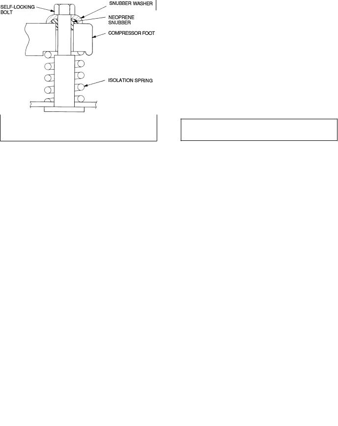
Table 2 Ð Weight Distribution
|
|
|
|
|
|
|
|
|
WEIGHT |
|
|
|
|
|
|
|
|
|
||
UNIT |
Total |
|
|
|
|
|
|
Support Point |
|
|
|
|
|
|
|
|||||
38AKS |
Operating |
|
A |
|
B |
|
C |
D |
|
|
E |
|
F |
|||||||
|
lb |
kg |
lb |
|
kg |
lb |
|
kg |
lb |
|
kg |
lb |
|
kg |
lb |
|
kg |
lb |
|
kg |
013 |
732 |
332 |
94 |
|
43 |
93 |
|
42 |
93 |
|
42 |
149 |
|
68 |
151 |
|
68 |
152 |
|
69 |
013C |
825 |
374 |
119 |
|
54 |
116 |
|
53 |
115 |
|
52 |
157 |
|
71 |
159 |
|
72 |
159 |
|
72 |
014 |
779 |
353 |
95 |
|
43 |
94 |
|
43 |
94 |
|
43 |
164 |
|
74 |
166 |
|
75 |
166 |
|
75 |
014C |
919 |
417 |
131 |
|
59 |
129 |
|
59 |
128 |
|
58 |
176 |
|
80 |
177 |
|
80 |
178 |
|
81 |
016 |
789 |
358 |
95 |
|
43 |
95 |
|
43 |
96 |
|
44 |
167 |
|
76 |
168 |
|
76 |
168 |
|
76 |
016C |
929 |
421 |
131 |
|
59 |
130 |
|
59 |
130 |
|
59 |
178 |
|
81 |
180 |
|
82 |
180 |
|
82 |
024 |
900 |
408 |
119 |
|
54 |
114 |
|
52 |
113 |
|
51 |
179 |
|
81 |
185 |
|
84 |
190 |
|
86 |
024C |
1040 |
472 |
155 |
|
70 |
150 |
|
68 |
146 |
|
66 |
191 |
|
87 |
196 |
|
89 |
202 |
|
92 |
Step 2 Ð Rig and Mount the Unit
Be sure unit panels are securely in place prior to rigging.
RIGGING Ð These units are designed for overhead rigging only. For this purpose, the transverse base channels extend beyond the sides of the unit, with holes provided in the end plates to attach cables or hooks. Rig with top skid packaging assembly in place to prevent unit damage by the rigging cable. As further protection for the coil faces, plywood sheets can be placed against the sides of the unit, behind the cables. Run the cables to a central suspension point so that the angle from the horizontal is not less than 45 degrees. Raise and set the unit down carefully.
If it is necessary to roll the unit into position, mount the unit on longitudinal rails, using a minimum of 3 rollers. Apply force to the rails, not the unit. If the unit is to be skidded into position, place it on a large pad and drag it by the pad. Do not apply any force to the unit.
Raise from above to lift unit from the rails or pad when unit is in ®nal position.
COMPRESSOR MOUNTING Ð As shipped, the compressor is held tightly in place by self-locking bolts. Before starting unit, loosen self-locking bolts until the snubber washer can be moved sideways with ®nger pressure. Do not remove shipping bolts. See Fig. 3.
Step 3 Ð Complete Refrigerant Piping
Connections
IMPORTANT: A refrigerant receiver is not provided with the unit. Do not install a receiver.
SIZE REFRIGERANT LINES Ð Consider the length of piping required between outdoor unit and indoor unit (evaporator), the amount of liquid lift, and compressor oil return. See Tables 3-5B and also refer to Part 3 of Carrier System Design Manual and E20-IIt software for design details and line sizing. Refer to indoor unit installation instructions for additional information.
NOTE: Use the piping data in Tables 3-5B as a general guide only. For more precise calculations, refer to Carrier System Design manual or E20-II software.
Condensing units with multiple-step unloading may require double suction risers to assure proper oil return at minimum load operating condition. See Tables 4A-5B and Fig. 4. Reduction of evaporator coil surface should be analyzed to provide sufficient refrigerant velocity to return oil to the compressor. Liquid line solenoid valves may be used in certain situations to accomplish this. Hot gas bypass, if used, should be introduced before the evaporator.
Note that refrigerant suction piping should be insulated.
Table 3 Ð Liquid Line Data
|
MAXIMUM |
|
|
|
||
|
ALLOWABLE |
|
LIQUID LINE |
|||
|
LIQUID LIFT |
|
||||
|
|
|
|
|||
UNIT |
ft (m) |
|
|
|
||
38AKS |
|
|
Maximum |
Maximum |
Filter Drier |
|
|
|
Allowable |
Allowable |
and |
||
|
|
|
||||
|
60 Hz |
50 Hz |
Pressure |
Temp. |
Sight Glass |
|
|
|
|
Drop |
Loss |
Flare Conn.* |
|
|
|
|
psig (kPa) |
F (C) |
in. (mm) |
|
013 |
52 (15.8) |
|
|
|
||
014 |
67 (20.4) |
7 (48.3) |
2 (1.1) |
5¤8 (15.88) |
||
016 |
82 (25.0 |
|||||
|
|
|
||||
024 |
87 (26.5) |
86 (26) |
|
|
|
|
|
|
|
|
|
|
|
*Inlet and outlet.
NOTE: Data shown is for units operating at 45 F (7.2 C) saturated suction and 95 F (35 C) entering air.
Fig. 3 Ð Compressor Mounting
8
 Loading...