

Page 1
Default Login Details
User’s Guide
NBG-418N v2
Wireless N300 Home Router
Web Address http://myrouter (router mode)
LAN IP
Address
User Name admin
Password 1234
htt p ://192.168.1.1 (router mode)
htt p ://192.168.1.2 (non-router
mode)
Version 1.00 Edition 3, 07/2018
Copyright © 2018 Zyxel Communications Corporation
Page 2

IMPORTANT!
READ CAREFULLY BEFORE USE.
KEEP THIS GUIDE FOR FUTURE REFERENCE.
Screenshots and graphics in this book may differ slightly from what you see due to differences in release
versions or your computer operating system. Every effort has been made to ensure that the information
in this manual is accurate.
Re lated Doc ume ntation
•Quick Start Guide
The Quick Start Guide shows how to connect the managed device.
•More Information
Go to suppo rt.zyxe l.c om to find other information on the NBG-418N v2.
NBG-418N v2 User’s Guide
2
Page 3

Contents Overview
Conte nts Ove rvie w
Use r’s G uide ......................................................................................................................................10
Introduction ........................................................................................................................................... 11
The Web Configurator ......................................................................................................................... 16
Connection Wizard .............................................................................................................................. 19
Modes .................................................................................................................................................... 28
Tutorials .................................................................................................................................................. 46
Te c hnic a l Re fere nc e ........................................................................................................................59
Wireless LAN .......................................................................................................................................... 60
WAN ....................................................................................................................................................... 76
LAN ......................................................................................................................................................... 96
DHCP Server .......................................................................................................................................... 99
Network Address Translation ............................................................................................................. 103
Dynamic DNS ...................................................................................................................................... 112
Static Route ......................................................................................................................................... 114
Firewall ................................................................................................................................................. 116
Content Filter ....................................................................................................................................... 120
Remote Management ....................................................................................................................... 122
Universal Plug-and-Play (UPnP) ......................................................................................................... 125
Bandwidth MGMT ............................................................................................................................... 133
System .................................................................................................................................................. 136
Logs ...................................................................................................................................................... 139
Tools ...................................................................................................................................................... 141
Sys OP Mode ....................................................................................................................................... 146
Language ............................................................................................................................................ 148
Troubleshooting .................................................................................................................................. 149
NBG-418N v2 User’s Guide
3
Page 4

Table of Contents
Ta ble of Conte nts
Co ntents Ove rview .............................................................................................................................3
Ta b le o f Co ntents.................................................................................................................................4
Pa rt I: Use r’s G uide .......................................................................................... 10
Cha pter 1
Introduc tion ........................................................................................................................................11
1.1 Overview ......................................................................................................................................... 11
1.2 Securing the NBG-418N v2 ............................................................................................................ 12
1.3 LEDs .................................................................................................................................................. 13
1.4 The WPS/RESET Button .................................................................................................................... 13
1.4.1 Using the WPS/RESET Button ................................................................................................. 14
1.5 Wall Mounting ................................................................................................................................. 14
Cha pter 2
The We b Co nfig ura tor........................................................................................................................16
2.1 Overview ......................................................................................................................................... 16
2.2 Accessing the Web Configurator ................................................................................................. 16
2.3 Resetting the NBG-418N v2 ........................................................................................................... 18
Cha pter 3
Co nne c tion Wizard ............................................................................................................................19
3.1 Wizard Setup ................................................................................................................................... 19
3.2 Connection Wizard: STEP 1: WAN Connection Type .................................................................. 20
3.2.1 PPPoE Connection ................................................................................................................ 21
3.2.2 Dynamic IP Connection ....................................................................................................... 22
3.2.3 Static IP Connection ............................................................................................................. 23
3.3 Connection Wizard: STEP 2: Wireless LAN ....................................................................................24
3.4 Connection Wizard: STEP 3: Internet Configuration ................................................................... 26
3.5 Connection Wizard Complete ...................................................................................................... 26
Cha pter 4
Mo de s .................................................................................................................................................28
4.1 Overview ......................................................................................................................................... 28
4.2 Setting your NBG-418N v2 to Router Mode ................................................................................. 29
4.2.1 Status Screen (Router Mode) ..............................................................................................30
4.2.2 Router Mode Navigation Panel .......................................................................................... 34
NBG-418N v2 User’s Guide
4
Page 5

Table of Contents
4.3 Setting your NBG-418N v2 to AP Mode ........................................................................................36
4.3.1 Status Screen (AP Mode) ..................................................................................................... 36
4.3.2 AP Navigation Panel ............................................................................................................. 38
4.4 Setting your NBG-418N v2 to Universal Repeater Mode ............................................................ 39
4.4.1 Status Screen (Universal Repeater Mode) ......................................................................... 39
4.4.2 Universal Repeater Navigation Panel ................................................................................. 41
4.5 Setting your NBG-418N v2 to Client Bridge Mode ...................................................................... 42
4.5.1 Status Screen (Client Bridge Mode) .................................................................................... 43
4.5.2 Universal Repeater Navigation Panel ................................................................................. 44
Cha pter 5
Tutorials ...............................................................................................................................................46
5.1 Overview ......................................................................................................................................... 46
5.2 How to Connect to the Internet from an AP ............................................................................... 46
5.3 Configure Wireless Security Using WPS on both your NBG-418N v2 and Wireless Client ........ 46
5.3.1 Push Button Configuration (PBC) ........................................................................................ 47
5.3.2 PIN Configuration .................................................................................................................. 48
5.4 Enable and Configure Wireless Security without WPS on your NBG-418N v2 .......................... 50
5.4.1 Configure Your Wireless Client ............................................................................................. 51
5.5 Using Multiple SSIDs on the NBG-418N v2 ..................................................................................... 53
5.5.1 Configuring Security Settings of Multiple SSIDs .................................................................. 54
5.6 Installing UPnP in Windows 7 Example .......................................................................................... 57
5.7 Using Bandwidth Management on the NBG-418N v2 ................................................................ 57
Pa rt II: Te c hnic al Re fe renc e ........................................................................... 59
Cha pter 6
Wireless LAN .......................................................................................................................................60
6.1 Overview ......................................................................................................................................... 60
6.2 What You Can Do .......................................................................................................................... 61
6.3 What You Should Know ................................................................................................................. 62
6.3.1 Wireless Security Overview ................................................................................................... 62
6.3.2 MBSSID .................................................................................................................................... 62
6.3.3 MAC Address Filter ................................................................................................................ 62
6.3.4 Encryption .............................................................................................................................. 63
6.3.5 WPS ......................................................................................................................................... 63
6.4 General Wireless LAN Screen ....................................................................................................... 63
6.4.1 No Security ............................................................................................................................. 65
6.4.2 WEP Encryption ..................................................................................................................... 66
6.4.3 WPA-PSK/WPA2-PSK .............................................................................................................. 67
6.5 MAC Filter ........................................................................................................................................ 68
NBG-418N v2 User’s Guide
5
Page 6

Table of Contents
6.6 Wireless LAN Advanced Screen ................................................................................................... 69
6.7 WPS Screen ..................................................................................................................................... 69
6.8 WPS Station Screen ........................................................................................................................ 70
6.9 Scheduling Screen ......................................................................................................................... 71
6.10 MBSSID Screen .............................................................................................................................. 72
6.11 AP Select Screen .......................................................................................................................... 73
6.12 WLAN Information Screen ........................................................................................................... 74
Cha pter 7
WAN ....................................................................................................................................................76
7.1 Overview ......................................................................................................................................... 76
7.2 What You Need To Know .............................................................................................................. 76
7.2.1 Configuring Your Internet Connection ............................................................................... 76
7.3 Internet Connection Screen .......................................................................................................... 77
7.3.1 Ethernet Encapsulation ........................................................................................................ 77
7.3.2 PPPoE Encapsulation ............................................................................................................ 79
7.3.3 PPTP Encapsulation ............................................................................................................... 81
7.3.4 DS-Lite ..................................................................................................................................... 83
7.4 Advanced Screen .......................................................................................................................... 83
7.5 IPv6 Screen ...................................................................................................................................... 84
Cha pter 8
LA N ......................................................................................................................................................96
8.1 Overview ......................................................................................................................................... 96
8.2 What You Need To Know .............................................................................................................. 96
8.2.1 IP Address and Subnet Mask ...............................................................................................97
8.2.2 DNS Server Address Assignment .......................................................................................... 97
8.2.3 IP Pool Setup .......................................................................................................................... 98
8.2.4 LAN TCP/IP ............................................................................................................................. 98
8.3 LAN IP Screen .................................................................................................................................. 98
Cha pter 9
DHC P Serve r........................................................................................................................................99
9.1 Overview ......................................................................................................................................... 99
9.2 What You Can Do .......................................................................................................................... 99
9.3 What You Need To Know .............................................................................................................. 99
9.4 General Screen ............................................................................................................................... 99
9.5 Static DHCP Screen ................................................................................................................... 100
9.6 Client List Screen ........................................................................................................................... 101
Cha pter 10
Ne twork Addre ss Tra nslatio n ..........................................................................................................103
10.1 Overview .................................................................................................................................. 103
NBG-418N v2 User’s Guide
6
Page 7

Table of Contents
10.2 What You Can Do ...................................................................................................................... 103
10.2.1 What You Need To Know ................................................................................................. 104
10.3 General NAT Screen ................................................................................................................... 105
10.4 NAT Application Screen ........................................................................................................... 106
10.5 Port Triggering Screen ................................................................................................................ 107
10.6 Technical Reference .................................................................................................................. 109
10.6.1 NAT Port Forwarding: Services and Port Numbers ......................................................... 109
10.6.2 NAT Port Forwarding Example ......................................................................................... 109
10.6.3 Trigger Port Forwarding .................................................................................................... 110
10.6.4 Trigger Port Forwarding Example .................................................................................... 110
10.6.5 Two Points To Remember About Trigger Ports ............................................................... 111
Cha pter 11
Dyna m ic DNS ...................................................................................................................................112
11.1 Overview .................................................................................................................................... 112
11.2 Dynamic DNS Screen ............................................................................................................... 112
Cha pter 12
Sta tic Ro ute .......................................................................................................................................114
12.1 Overview .................................................................................................................................. 114
12.2 IP Static Route Screen ............................................................................................................... 114
Cha pter 13
Fire wall..............................................................................................................................................116
13.1 Overview ................................................................................................................................... 116
13.2 What You Can Do ...................................................................................................................... 116
13.3 What You Need To Know .......................................................................................................... 117
13.3.1 About the NBG-418N v2 Firewall ..................................................................................... 117
13.3.2 VPN Pass Through Features .............................................................................................. 117
13.4 General Firewall Screen .......................................................................................................... 117
13.5 Services Screen ........................................................................................................................ 118
Cha pter 14
Co ntent Filte r....................................................................................................................................120
14.1 Overview ..................................................................................................................................... 120
14.2 What You Can Do ...................................................................................................................... 120
14.3 Filter Screen .............................................................................................................................. 120
Cha pter 15
Re mo te Manag eme nt.....................................................................................................................122
15.1 Overview ..................................................................................................................................... 122
15.1.1 Remote Management Limitations .................................................................................. 123
15.1.2 Remote Management and NAT ..................................................................................... 123
NBG-418N v2 User’s Guide
7
Page 8

Table of Contents
15.1.3 System Timeout .................................................................................................................. 123
15.2 WWW Screen ........................................................................................................................... 123
Cha pter 16
Unive rsa l Plug- a nd - Play (UPnP) ......................................................................................................125
16.1 Overview .................................................................................................................................... 125
16.2 What You Need to Know ........................................................................................................... 125
16.3 Configuring UPnP ........................................................................................................................ 126
16.4 Installing UPnP in Windows 7 Example ......................................................................................126
16.4.1 Using UPnP in Windows XP Example ................................................................................ 128
16.4.2 Web Configurator Easy Access ....................................................................................... 130
Cha pter 17
Ba ndwidth MG MT.............................................................................................................................133
17.1 Overview ..................................................................................................................................... 133
17.2 What You Can Do ...................................................................................................................... 133
17.3 What You Need To Know .......................................................................................................... 133
17.4 Bandwidth MGMT Screen ......................................................................................................... 133
17.5 Advanced Screen ..................................................................................................................... 134
Cha pter 18
Syste m ...............................................................................................................................................136
18.1 Overview ..................................................................................................................................... 136
18.2 What You Can Do ...................................................................................................................... 136
18.3 System General Screen ............................................................................................................ 136
18.4 Time Setting Screen .................................................................................................................... 137
Cha pter 19
Lo g s ...................................................................................................................................................139
19.1 Overview ..................................................................................................................................... 139
19.2 What You Need to Know ........................................................................................................... 139
19.3 View Log Screen ......................................................................................................................... 139
Cha pter 20
To ols ..................................................................................................................................................141
20.1 Overview ..................................................................................................................................... 141
20.2 What You Can Do ...................................................................................................................... 141
20.3 Firmware Upload Screen ........................................................................................................... 141
20.4 Configuration Screen ................................................................................................................. 143
20.4.1 Backup Configuration ...................................................................................................... 143
20.4.2 Restore Configuration ...................................................................................................... 143
20.4.3 Back to Factory Defaults .................................................................................................. 144
20.5 Restart Screen ............................................................................................................................. 144
NBG-418N v2 User’s Guide
8
Page 9

Table of Contents
Cha pter 21
Sys O P Mod e ....................................................................................................................................146
21.1 Overview ..................................................................................................................................... 146
21.2 General Screen ........................................................................................................................... 146
Cha pter 22
La ng uag e .........................................................................................................................................148
22.1 Language Screen ....................................................................................................................... 148
Cha pter 23
Tro uble shoo ting ................................................................................................................................149
23.1 Power, Hardware Connections, and LEDs ............................................................................... 149
23.2 NBG-418N v2 Access and Login ............................................................................................... 150
23.3 Internet Access ........................................................................................................................... 151
23.4 Resetting the NBG-418N v2 to Its Factory Defaults ................................................................. 152
23.5 Wireless Problems ........................................................................................................................ 153
Appendix A Customer Support ..................................................................................................... 154
Appendix B IP Addresses and Subnetting .................................................................................... 160
Appendix C Pop-up Windows, JavaScripts and Java Permissions............................................ 169
Appendix D Setting Up Your Computer’s IP Address.................................................................. 178
Appendix E Wireless LANs............................................................................................................... 205
Appendix F Common Services ...................................................................................................... 218
Appendix G Legal Information...................................................................................................... 221
Inde x .................................................................................................................................................229
NBG-418N v2 User’s Guide
9
Page 10

PART I
Use r’s Guide
10
Page 11
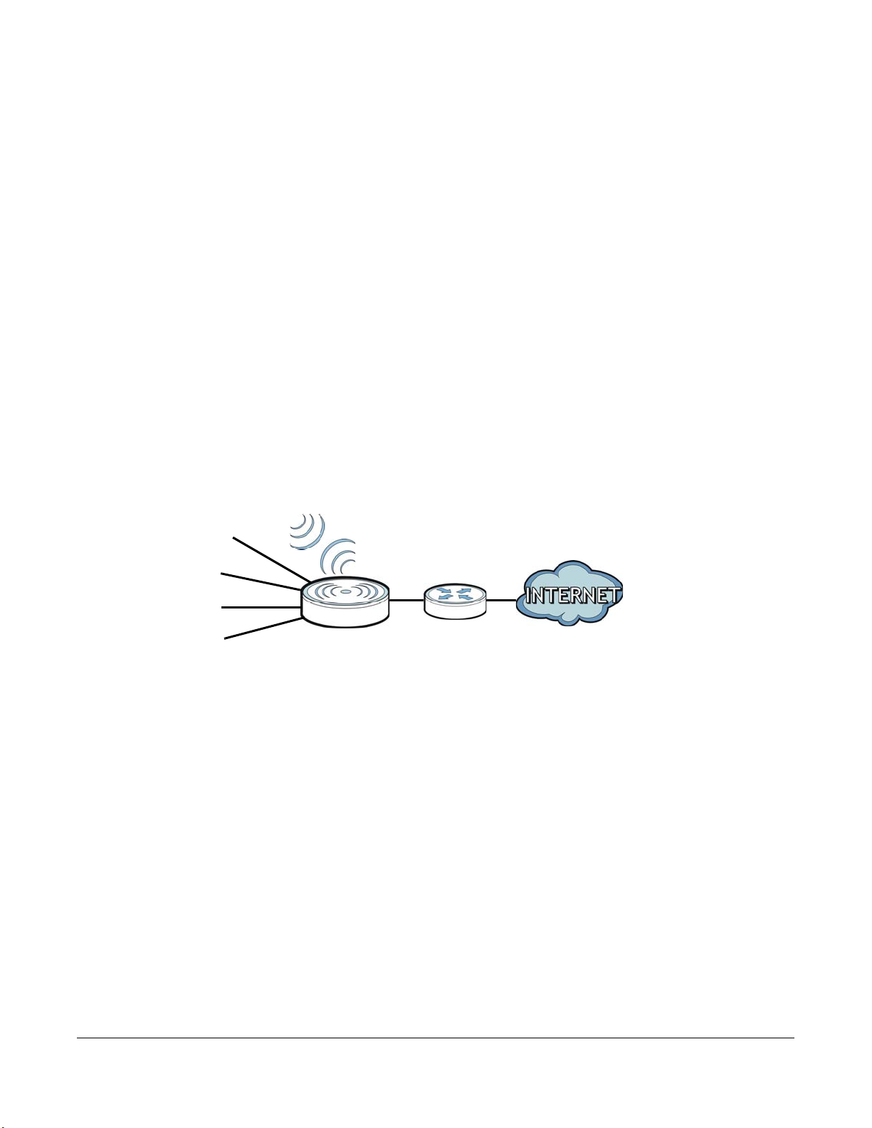
1.1 O ve rvie w
WLAN
WAN
LAN1
LAN2
LAN3
LAN4
The NBG-418N v2 extends the range of your existing wired network without additional wiring, providing
easy network access to mobile users.
Your can create the following connections using the NBG-418N v2:
• LAN. You can connect network devices via the Ethernet ports of the NBG-418N v2 so that they can
communicate with each other and access the Internet.
• WLAN. Wireless clients can connect to the NBG-418N v2 to access network resources.
• WAN. Connect to a broadband modem/router for Internet access.
Figure 1 NBG-418N v2 Network
C HAPTER 1
Introduc tion
You can set up the NBG-418N v2 with other IEEE 802.11b/g/n compatible devices in one of the following
device modes:
•Router
• Access Point
• Universal Repeater
• Client Bridge
NBG-418N v2 User’s Guide
11
Page 12
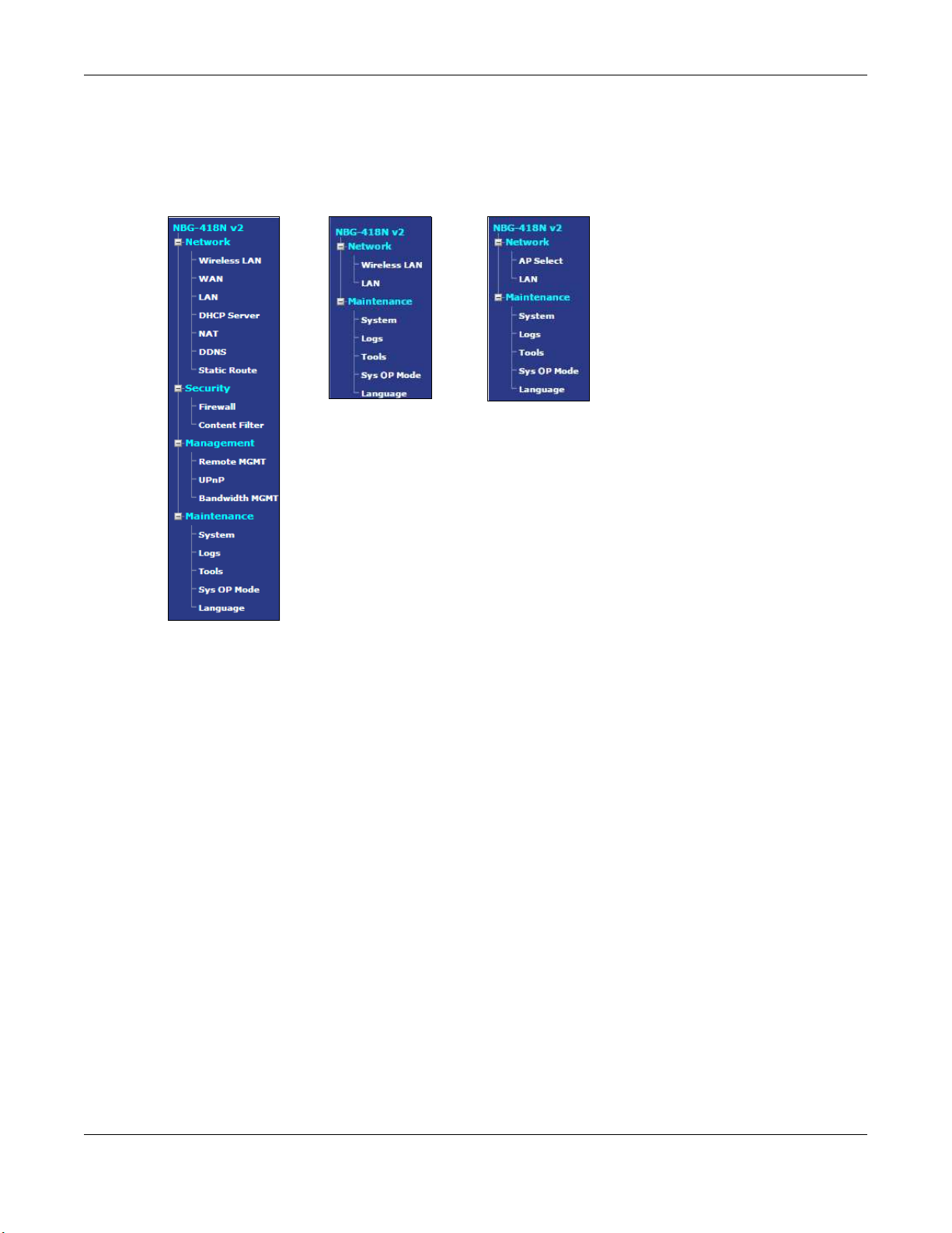
Chapter 1 Introduction
Use a (supported) web browser to manage the NBG-418N v2. Menus vary according to which mode
you’re using.
Router Mode AP or Universal
Repeater Mode
Client Bridge Mode
Chapter 4 on page 28 for more information on these modes.
See
1.2 Se c uring the NBG- 418N v2
Do the following things regularly to make the NBG-418N v2 more secure and to manage the NBG-418N
v2 more effectively.
• Change the password. Use a password that’s not easy to guess and that consists of different types of
characters, such as numbers and letters.
• Write down the password and put it in a safe place.
• Back up the configuration (and make sure you know how to restore it). Restoring an earlier working
configuration may be useful if the device becomes unstable or even crashes. If you forget your
password, you will have to reset the NBG-418N v2 to its factory default settings. If you backed up an
earlier configuration file, you would not have to totally re-configure the NBG-418N v2. You could
simply restore your last configuration.
NBG-418N v2 User’s Guide
12
Page 13
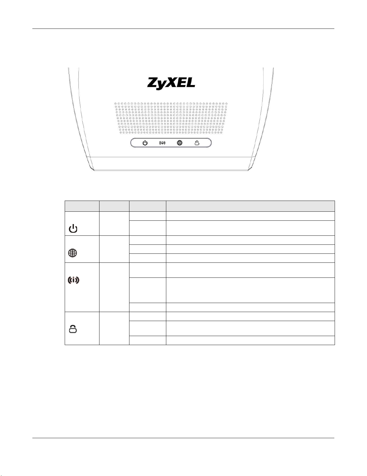
1.3 LEDs
Figure 2 Front Panel
The following table describes the LEDs and the WPS button.
Table 1 Front Panel LEDs and WPS Button
LED CO LO R STATUS DESCRIPTIO N
POWER Green On The NBG-418N v2 is receiving power and functioning properly.
Chapter 1 Introduction
Off The NBG-418N v2 is not receiving power.
WAN Green On The NBG-418N v2 has a successful 10/100MB WAN connection.
Blinking The NBG-418N v2 is sending/receiving data through the WAN.
Off The WAN connection is not ready, or has failed.
WLAN Green On The NBG-418N v2 is ready, but is not sending/receiving data through
Blinking The NBG-418N v2 is sending/receiving data through the wireless LAN.
Off The wireless LAN is not ready or has failed.
WPS Green On WPS status is configured.
Blinking The NBG-418N v2 is negotiating a WPS connection with a wireless
Off The WPS status is not configured or disabled.
1.4 The WPS/ RESET Button
Your NBG-418N v2 supports WiFi Protected Setup (WPS), which is an easy way to set up a secure wireless
network. WPS is an industry standard specification, defined by the Wi-Fi Alliance.
WPS allows you to quickly set up a wireless network with strong security, without having to configure
security settings manually. Each WPS connection works between two devices. Both devices must
support WPS (check each device’s documentation to make sure).
the wireless LAN.
The NBG-418N v2 is negotiating a WPS connection with a wireless
client.
client.
NBG-418N v2 User’s Guide
13
Page 14

Chapter 1 Introduction
Depending on the devices you have, you can either press a button (recommended) on the device
itself, or in its configuration utility or enter a PIN (a unique Personal Identification Number that allows one
device to authenticate the other) in each of the two devices. When WPS is activated on a device, it has
two minutes to find another device that also has WPS activated. Then, the two devices connect and set
up a secure network by themselves.
The WPS/ RESET single button is located at the back panel of the NBG-418N v2.
1.4.1 Using the WPS/ RESET Button
1 Make sure the power LED is on.
2 Press the WPS/ RESET button within 3 seconds to turn on the WPS function
3 Press the WPS/ RESET button for longer than 10 seconds to restart/reboot the NBG-418N v2 back to its
factory-default configurations.
For more information on using WPS/ RESET, see
1.5 Wa ll Mounting
You may need screw anchors if mounting on a concrete or brick wall.
Table 2 Wall Mounting Information
Distance between holes 10.50 cm
M4 Screws Two
Screw anchors (optional) Two
1 Select a position free of obstructions on a wall strong enough to hold the weight of the device.
2 Mark two holes on the wall at the appropriate distance apart for the screws.
Be c are ful to a void da ma ging pipe s o r c able s loc a ted inside the wa ll
whe n drilling ho les for the sc re ws.
3 If using screw anchors, drill two holes for the screw anchors into the wall. Push the anchors into the full
depth of the holes, then insert the screws into the anchors. Do not insert the screws all the way in - leave
a small gap of about 0.5 cm.
If not using screw anchors, use a screwdriver to insert the screws into the wall. Do not insert the screws all
the way in - leave a gap of about 0.5 cm.
Section 5.3 on page 46.
4 Make sure the screws are fastened well enough to hold the weight of the NBG-418N v2 with the
connection cables.
5 Align the holes on the back of the NBG-418N v2 with the screws on the wall. Hang the NBG-418N v2 on
the screws.
NBG-418N v2 User’s Guide
14
Page 15
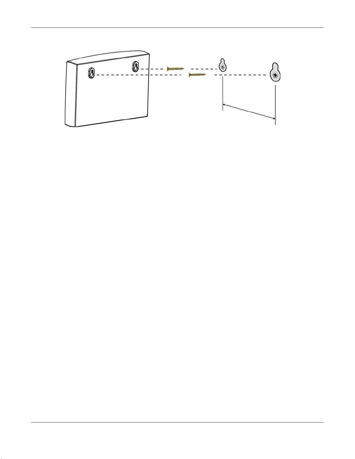
Figure 3 Wall Mounting Example
Chapter 1 Introduction
NBG-418N v2 User’s Guide
15
Page 16

2.1 O ve rvie w
This chapter describes how to access the NBG-418N v2 Web Configurator and provides an overview of
its screens.
The Web Configurator is an HTML-based management interface that allows easy setup and
management of the NBG-418N v2 via Internet browser. Use Internet Explorer 8.0 and later versions,
Mozilla Firefox, Google Chrome or Safari. The recommended screen resolution is 1024 by 768 pixels.
In order to use the Web Configurator you need to allow:
• Web browser pop-up windows from your device. Web pop-up blocking is enabled by default in
Windows XP SP (Service Pack) 2.
• JavaScript (enabled by default).
• Java permissions (enabled by default).
C HAPTER 2
The We b Configurator
Refer to
Explorer.
Chapter 23 Troubleshooting to see how to make sure these functions are allowed in Internet
2.2 Ac c e ssing the We b Config ura to r
1 Make sure your NBG-418N v2 hardware is properly connected and prepare your computer or computer
network to connect to the NBG-418N v2 (refer to the Quick Start Guide).
2 Launch your web browser.
3 When the NBG-418N v2 is in router mode, type “http://myrouter” or "http://192.168.1.1" as the website
address in your web browser. 192.168.1.1 is the default LAN IP address in router mode (the default
device mode). (The default IP address in non-router mode is 192.168.1.2).
Your computer must be in the same subnet in order to access this website address. In router mode, the
NBG-418N v2 can assign your computer an IP address, so you must set your computer to get an IP
address automatically (computer factory default) or give it a fixed IP address in the range between
192.168.1.3 and 192.168.1.254 (see the appendices).
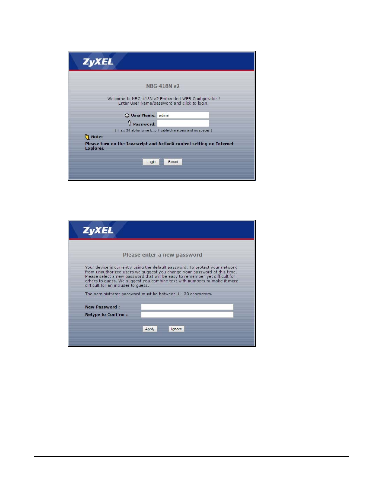
4 Type a d m in (default) as the user name and 12 34 (default) as the password and click O K.
NBG-418N v2 User’s Guide
16
Page 17
Chapter 2 The Web Configurator
Figure 4 Login Screen
5 You should see a screen asking you to change your password (highly recommended) as shown next.
Type a new password. Click Apply to save your changes. Click Ig nore if you do not want to change the
password this time.
Figure 5 Change Password Screen
Note: The management session automatically times out when the time period set in the
Administra tor Ina c tivity Time r field expires (default five minutes). Simply log back into
the NBG-418N v2 if this happens.
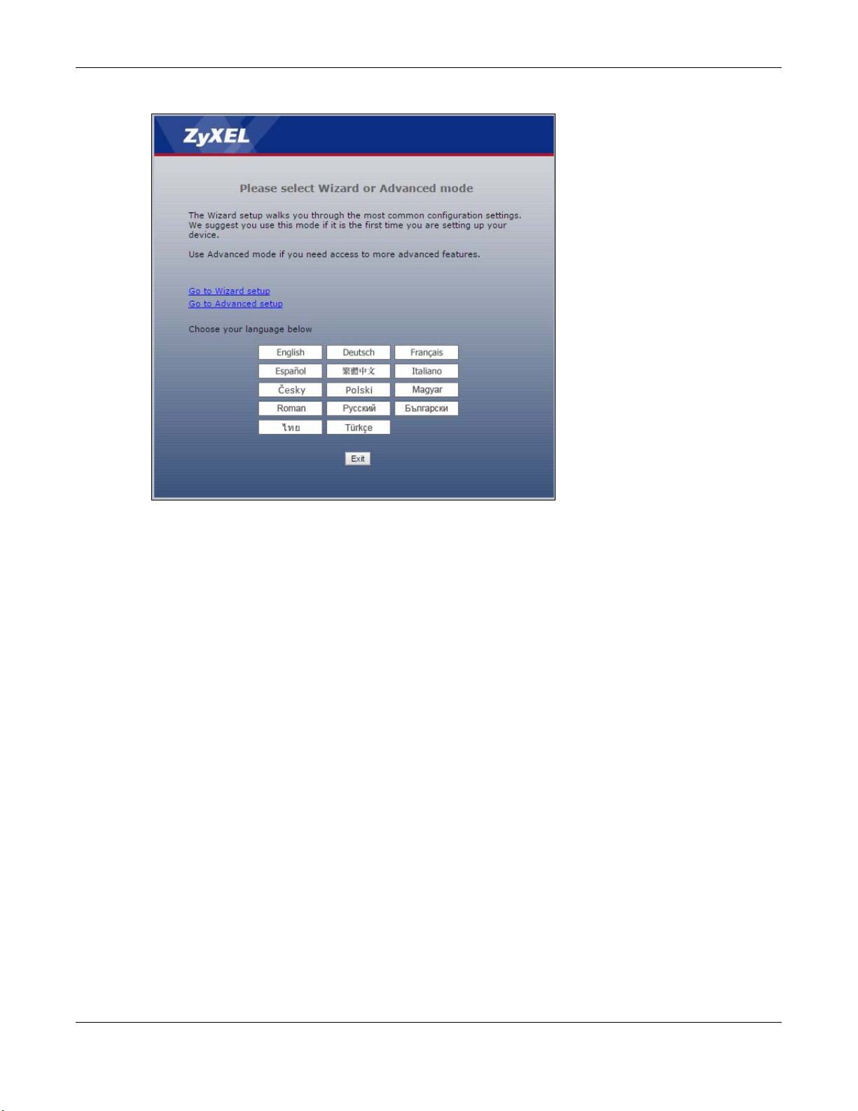
6 Select the setup type you want to use.
• Click G o to Wizard Setup to use the Configuration Wizard for basic Internet and Wireless setup.
• Click G o to A d vanc ed Setup to view and configure all the NBG-418N v2’s settings.
• Select a language to go to the basic Web Configurator in that language. To change to the
advanced configurator see
Chapter 22 on page 148.
NBG-418N v2 User’s Guide
17
Page 18
Chapter 2 The Web Configurator
Figure 6 Selecting the setup mode
2.3 Resetting the NBG- 418N v2
If you forget your password or IP address, or you cannot access the Web Configurator, you will need to
use the WPS/ RESET button at the back of the NBG-418N v2 to reload the factory-default configuration
file. This means that you will lose all configurations that you had previously saved, the username will be
reset to adm in and password will be reset to 12 34. The IP address will be reset to “192.168.1.1”.
Make sure the power LED is on and press the WPS/ RESET button for longer than 10 seconds to restart/
reboot and set the NBG-418N v2 back to its factory-default configurations.
NBG-418N v2 User’s Guide
18
Page 19
3.1 Wiza rd Setup
This chapter provides information on the wizard setup screens in the Web Configurator.
The Web Configurator’s wizard setup helps you configure your device to access the Internet. Leave a
field blank if you don’t have that information.
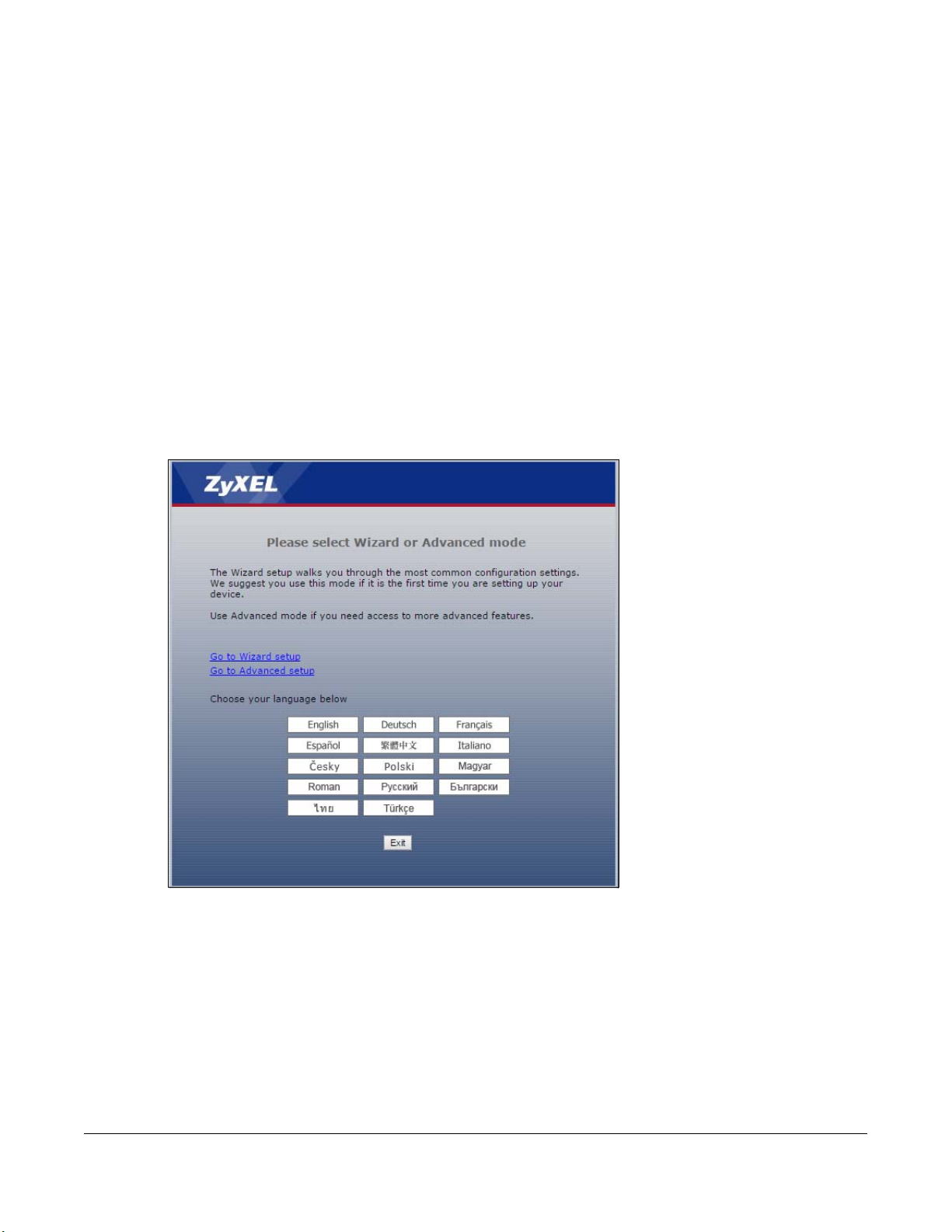
1 After you access the NBG-418N v2 Web Configurator, click G o to Wizard se tup.
Figure 7 Select Go to Wizard setup
C HAPTER 3
Conne c tion Wizard
NBG-418N v2 User’s Guide
19
Page 20
Chapter 3 Connection Wizard
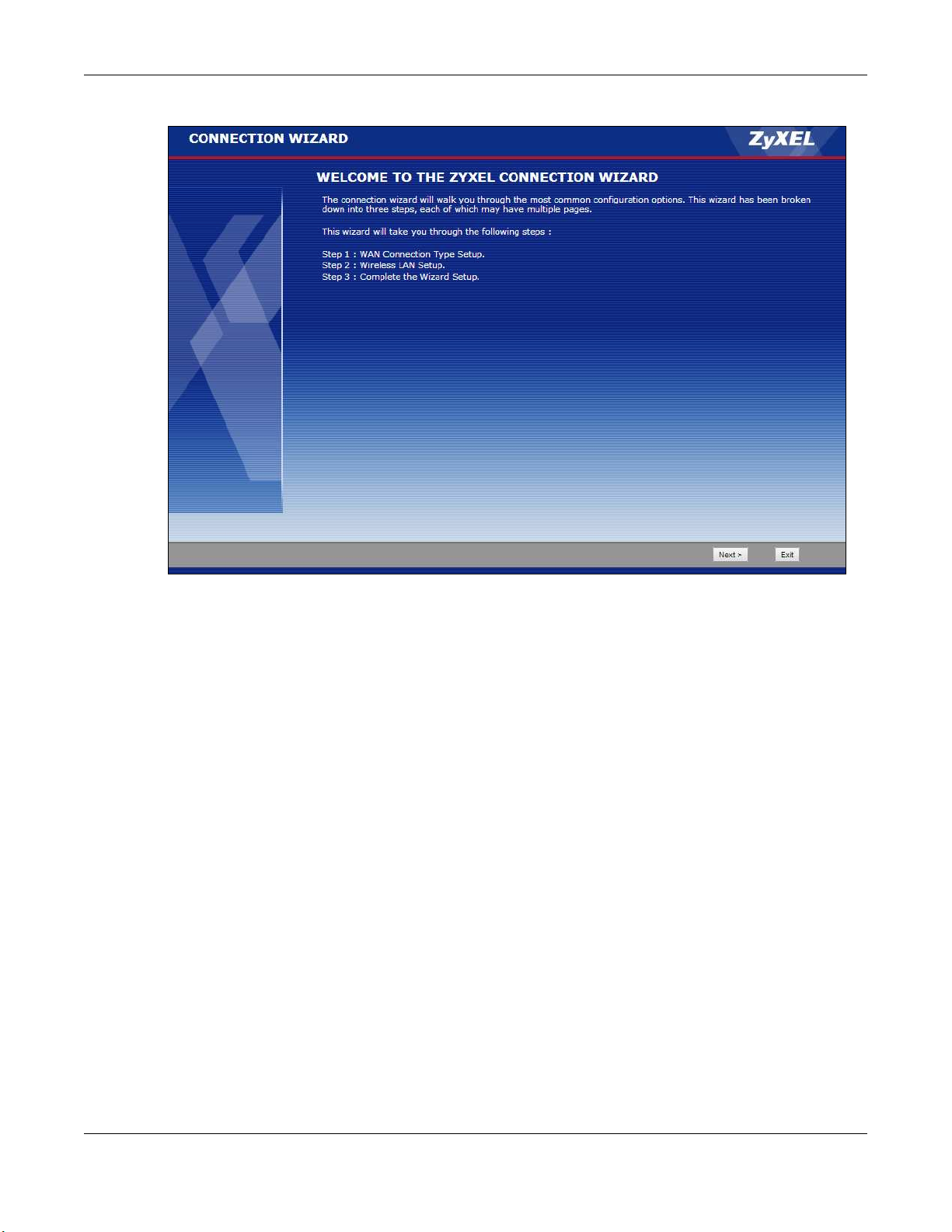
Figure 8 Welcome to the Connection Wizard
2 Read the on-screen information and click Ne xt.
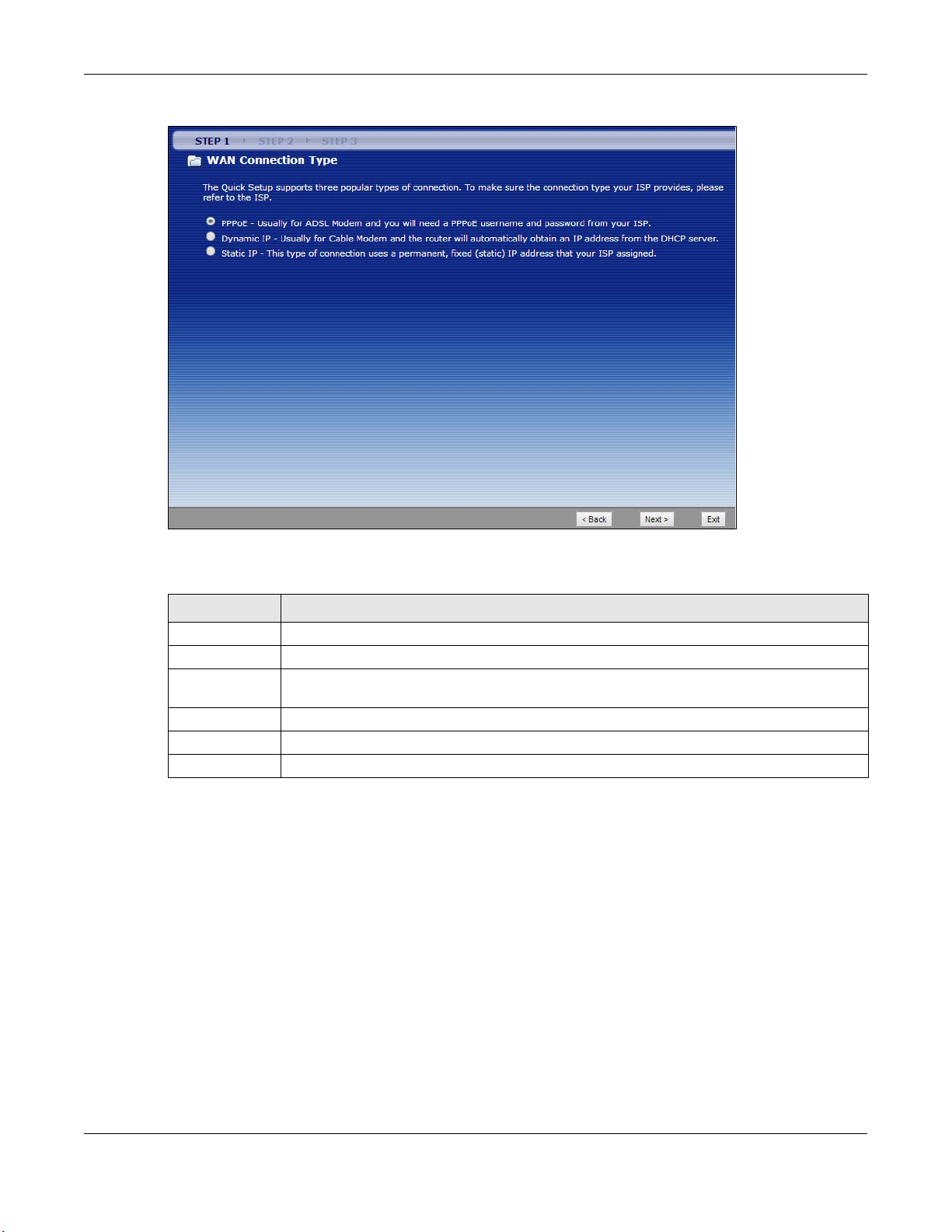
3.2 Conne c tion Wiza rd: STEP 1: WAN C onne c tion Type
The NBG-418N v2 offers three Internet connection types. They are PPP o ve r Ethe rne t (PPPoE), Dynam ic IP
or Static IP. You must select one from the check box in Step 1 of the Wizard. Check with your ISP to make
sure you use the correct type.
NBG-418N v2 User’s Guide
20
Page 21
Chapter 3 Connection Wizard
Figure 9 Wizard Step 1: WAN Connection Type
The following table describes the labels in this screen.
Table 3 Wizard Step 1: WAN Connection Type
LABEL DESCRIPTIO N
PPPoE Select PPPo E radio button for a dial-up connection.
Dynamic IP Select Dyna mic IP radio button if your ISP did not assign you a fixed IP address.
Static IP Select Sta tic IP radio button, provided by your ISP to give the NBG-418N v2 a fixed, unique IP
Address.
Back Click Ba ck to return to the previous screen.
Next Click Ne xt to proceed to the next screen.
Exit Click Exit to close the wizard screen without saving.
3.2.1 PPPoE Conne c tio n
Point-to-Point Protocol over Ethernet (PPPoE) functions as a dial-up connection. PPPoE is an IETF (Internet
Engineering Task Force) standard specifying how a host personal computer interacts with a broadband
modem (for example DSL, cable, wireless, etc.) to achieve access to high-speed data networks.
For the service provider, PPPoE offers an access and authentication method that works with existing
access control systems (for instance, RADIUS).
One of the benefits of PPPoE is the ability to let end users access one of multiple network services, a
function known as dynamic service selection. This enables the service provider to easily create and offer
new IP services for specific users.
Operationally, PPPoE saves significant effort for both the subscriber and the ISP/carrier, as it requires no
specific configuration of the broadband modem at the subscriber’s site.
NBG-418N v2 User’s Guide
21
Page 22
Chapter 3 Connection Wizard
By implementing PPPoE directly on the NBG-418N v2 (rather than individual computers), the computers
on the LAN do not need PPPoE software installed, since the NBG-418N v2 does that part of the task.
Furthermore, with NAT, all of the LAN's computers will have Internet access.
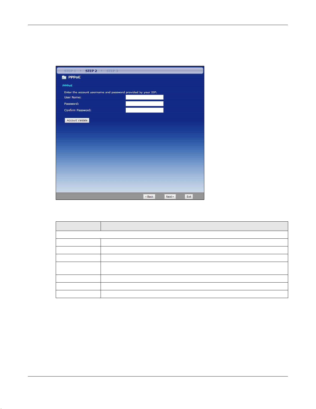
Figure 10 Wizard Step 2: PPPoE Connection
The following table describes the labels in this screen.
Table 4 Wizard Step 2: PPPoE Connection
LABEL DESCRIPTIO N
PPPoE
User Name Type the user name given to you by your ISP.
Password Type the password associated with the user name above.
Confirm Password Type the password again for confirmation.
Account Validate Click the Ac c o unt Va lida te button to establish the Internet connection via PPPoE
encapsulation.
Back Click Bac k to return to the previous screen.
Next Click Ne xt to continue.
Exit Click Exit to close the wizard screen without saving.
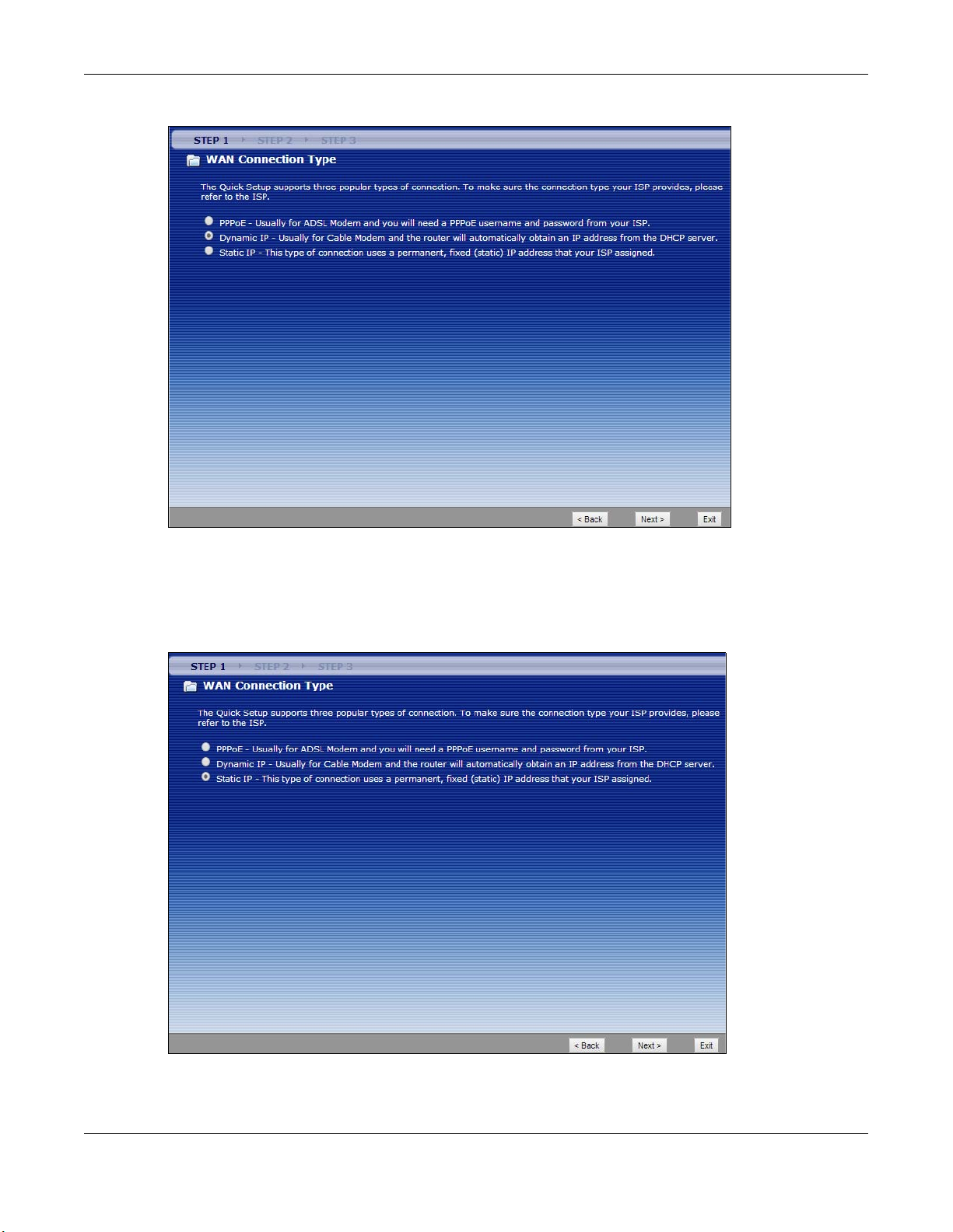
3.2.2 Dyna mic IP C o nne c tio n
Use the dynamic IP connection when your network administrator or ISP assigns your IP address
dynamically.
NBG-418N v2 User’s Guide
22
Page 23
Chapter 3 Connection Wizard
Figure 11 Wizard Step 1: Dynamic IP Connection
3.2.3 Static IP Conne c tion
The following wizard screen allows you to assign a fixed IP address to the NBG-418N v2
Figure 12 Wizard Step 2: Static IP
Click Ne xt to open the following screen.
NBG-418N v2 User’s Guide
23
Page 24
Chapter 3 Connection Wizard
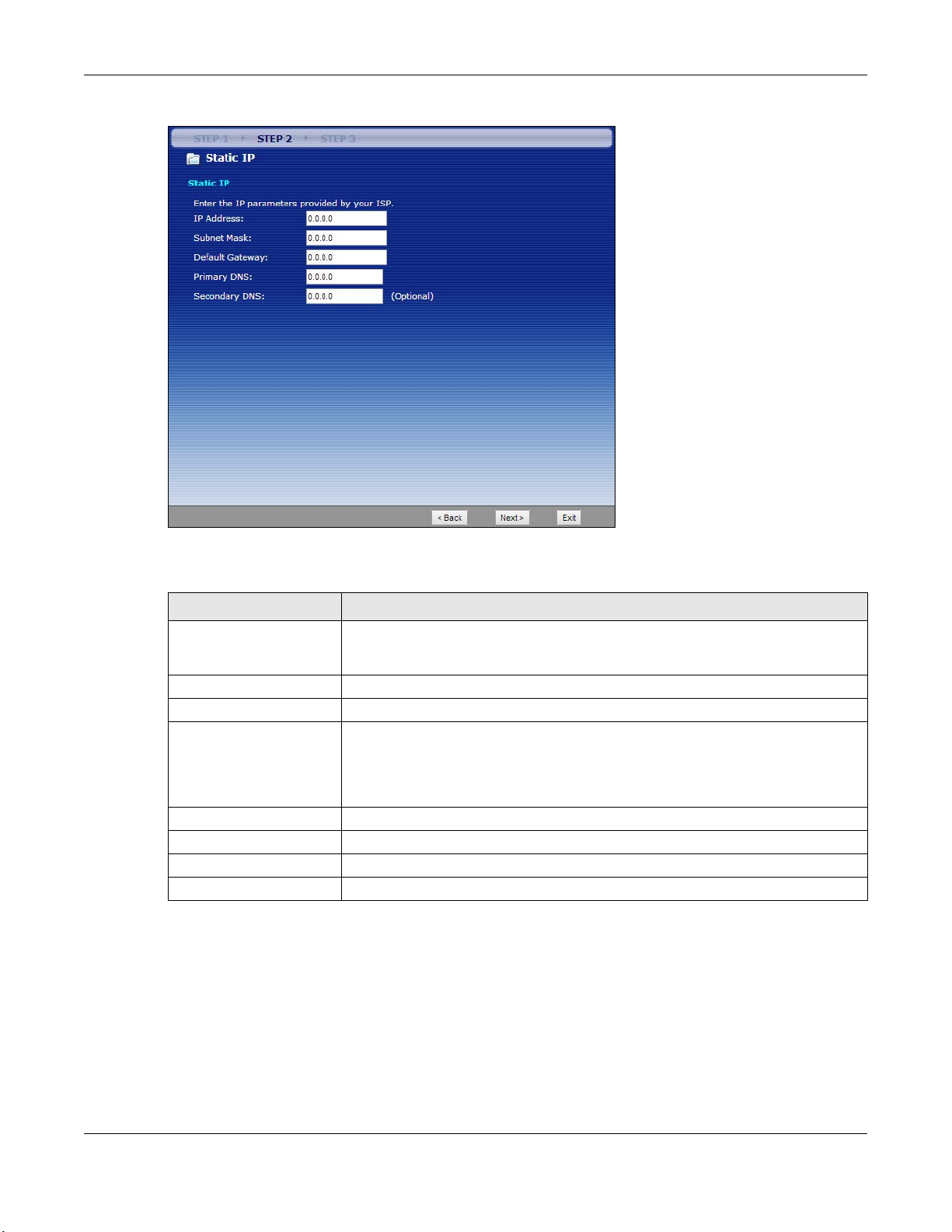
Figure 13 Wizard Step 2: Static IP Connection
The following table describes the labels in this screen
Table 5 Wizard Step 2: Static IP Connection
LABEL DESCRIPTIO N
IP Address Select this option if you were given IP address and/or DNS server settings by the ISP.
Subnet Mask Enter the subnet mask address in this field.
Default Gateway Enter the gateway IP address provided by your ISP.
Primary DNS DNS (Domain Name System) is for mapping a domain name to its corresponding IP
Secondary DNS Enter the secondary DNS server’s IP address in this field. This field is optional.
Back Click Ba c k to return to the previous screen.
Next Click Ne xt to continue.
Exit Click Exit to close the wizard screen without saving.
The fixed IP address should be in the same subnet as your broadband modem or
router.
address and vice versa. The DNS server is extremely important because without it, you
must know the IP address of a computer before you can access it. The NBG-418N v2
uses a system DNS server (in the order you specify here) to resolve domain names for
DDNS and the time server. Enter the primary DNS server’s IP address in this field.
Click Ne xt to configure the WLAN for the NBG-418N v2.
3.3 Conne c tion Wiza rd: STEP 2: Wirele ss LAN
Set up your wireless LAN using the following screen.
NBG-418N v2 User’s Guide
24
Page 25
Chapter 3 Connection Wizard
Figure 14 Wizard Step 2: Wireless LAN
The following table describes the labels in this screen.
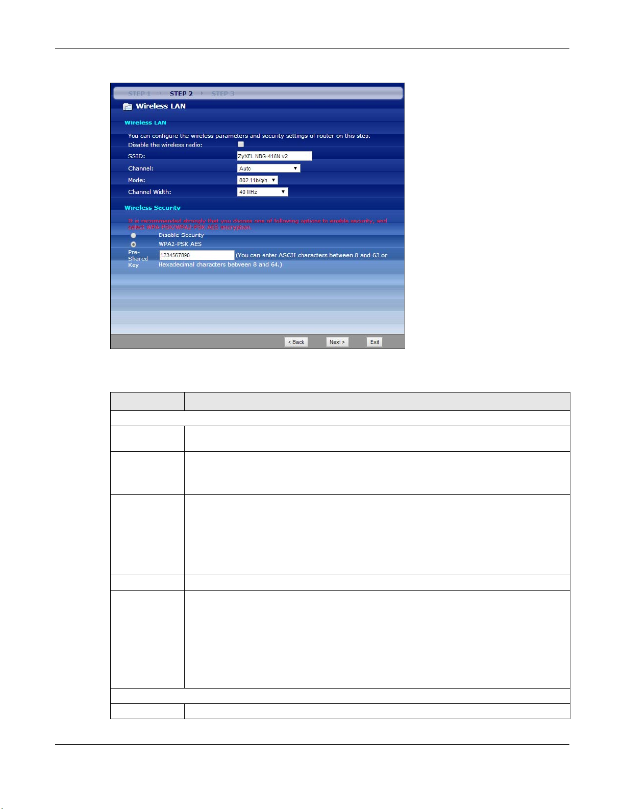
Table 6 Wizard Step 2: Wireless LAN
LABEL DESCRIPTIO N
Wireless LAN
Disable the
wireless radio
SSID Enter a descriptive name (up to 32 printable 7-bit ASCII characters) for the wireless LAN.
Channel The range of radio frequencies used by IEEE 802.11b/g/n wireless devices is called a channel.
Mode Select the IEEE 802.11 WLAN mode you wish to use on the NBG-418N v2 from the drop-down list.
Channel Width Select the channel bandwidth you want to use for your wireless network.
Wireless Security
Disable Security Click this check box to disable security settings for the WLAN.
Click this check box to disable the WLAN in the NBG-418N v2.
If you change this field on the NBG-418N v2, make sure all wireless stations use the same SSID in
order to access the network.
Set the operating frequency/channel depending on your particular region. Select a channel
from the drop-down list box. The options vary depending on the frequency band and the
country you are in.
Select Auto to have the NBG-418N v2 automatically choose the channel with the least
interference.
Select Auto 20/ 40 MHz to allow the NBG-418N v2 to adjust the channel bandwidth to 40 MHz or
20 MHz depending on network conditions.
Select 20 MHz if you want to lessen radio interference with other wireless devices in your
neighborhood or the wireless clients do not support channel bonding.
Select 40 MHz to bond two adjacent radio channels to increase throughput. The wireless clients
must also support 40 MHz.
NBG-418N v2 User’s Guide
25
Page 26
Chapter 3 Connection Wizard
Table 6 Wizard Step 2: Wireless LAN (continued)
LABEL DESCRIPTIO N
WPA2-PSK AES Choose WPA2- PSK AES security to configure a Pre-Shared Key. Choose this option only if your
wireless clients support WPA2-PSK. You will need to enter a Pre-Shared Key in the box below.
Pre-Shared Key Type in a string of ASCII characters between 8 and 63 or hexadecimal characters between 8
and 64 for the Pre-Shared Key field.
Back Click Ba ck to display the previous screen.
Next Click Ne xt to proceed to the next screen.
Exit Click Exit to close the wizard screen without saving.
Note: The wireless stations and NBG-418N v2 must use the same SSID, channel ID, WPA-PSK (if
WPA-PSK is enabled) or WPA2-PSK (if WPA2-PSK is enabled) for wireless communication.
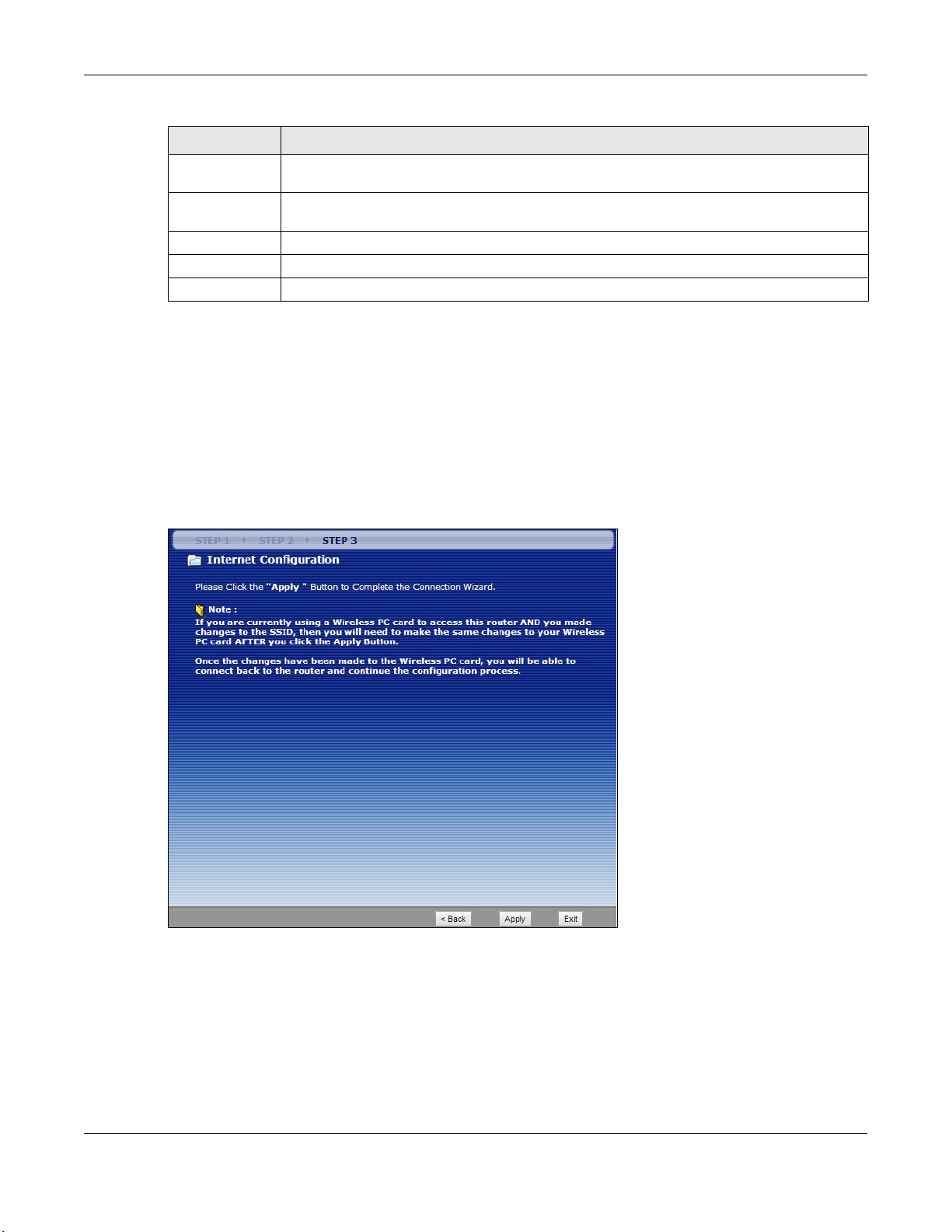
3.4 Conne c tion Wiza rd: STEP 3: Inte rne t Co nfig uratio n
Click Ap p ly to finish setting up your NBG-418N v2 to operate on your network and access the
Internet.This wizard screen varies according to the connection type that you select.
Figure 15 Wizard Step 3: Internet Configuration.
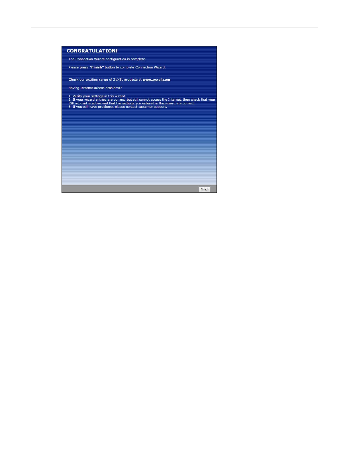
3.5 Conne c tion Wiza rd Comple te
Click Finish to complete the wizard setup.
NBG-418N v2 User’s Guide
26
Page 27
Chapter 3 Connection Wizard
Figure 16 Connection Wizard Complete
Well done! You have successfully set up your NBG-418N v2 to operate on your network and access the
Internet.
NBG-418N v2 User’s Guide
27
Page 28
4.1 O ve rvie w
LEW
WLAN
LAN
WAN
N
IAD
LEW
WLAN
LAN
WAN
N
R
You can set up the NBG-418N v2 with other IEEE 802.11b/g/n compatible devices in different device
modes.
Note: Choose your device mode carefully to avoid having to change it later. The NBG-418N
v2 automatically restarts when you change modes.
The default LAN IP address of the NBG-418N v2 in Router mode is 192.168.1.1. The
default IP address of the NBG-418N v2 in other modes is 192.168.1.2.
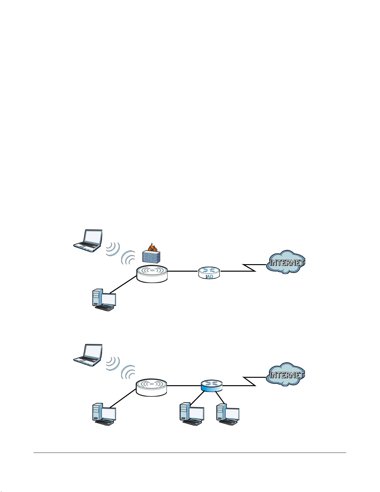
• Router: Use this mode if you want to use routing functions such as LAN DHCP, NAT, firewall and so on,
on the NBG-418N v2 (N). The NBG-418N v2 has separate LAN and WAN network IP addresses.
Connect the WAN port to an Internet Access Device (IAD) such as a broadband modem.
Figure 17 Router
C HAPTER 4
Mode s
• Ac ce ss Po int: Use this mode if you already have a Router (R) in your network and you want to set up a
wireless network and bridge t he wired and wireless connections on the NBG-416N.
Figure 18 AP Mode
NBG-418N v2 User’s Guide
28
Page 29
Chapter 4 Modes
LEW
N
AP
WLAN
N
AP
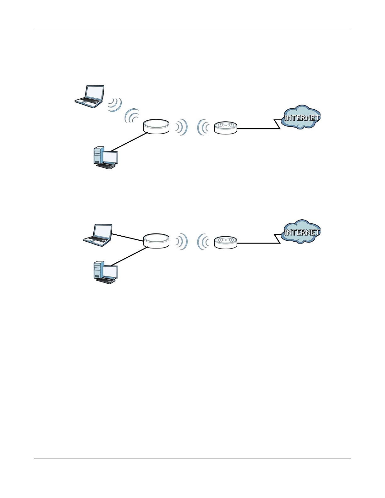
• Unive rsal Re p e ater: In this mode, the NBG-418N v2 (N) can be an access point and a wireless client at
the same time. Use this mode if there is an existing wireless router or access point in your network and
you want the NBG-418N v2 (N) to wirelessly relay communications from its wireless clients to the
access point.
Figure 19 Universal Repeater
• Clie nt Bridg e: Use this mode to have the NBG-418N v2 work only as a wireless client if there is an
existing wireless router or access point in the network to which you want to connect your local
network wirelessly. In this mode, you should know the SSID and wireless security details of the access
point to which you want to connect.
Figure 20 Client Bridge
4.2 Se tting your NBG-418N v2 to Route r Mo de
The NBG-418N v2 is set to wireless router mode by default. If it was changed and now you want to set it
back, do the following procedure.
1 Connect your computer to the LAN port of the NBG-418N v2.
2 The default LAN IP address of the NBG-418N v2 is 192.168.1.1 in router mode and 192.168.1.2 by default in
non-router mode. In router mode, the NBG-418N v2 can assign your computer an IP address, so you
must set your computer to get an IP address automatically (computer factory default) or give it a fixed
IP address in the range between 192.168.1.3 and 192.168.1.254.
3 After you’ve set your computer’s IP address, open a web browser such as Internet Explorer and type the
IP address of the NBG-418N v2 as the web address in your web browser.
4 Log into the Web Configurator. See the
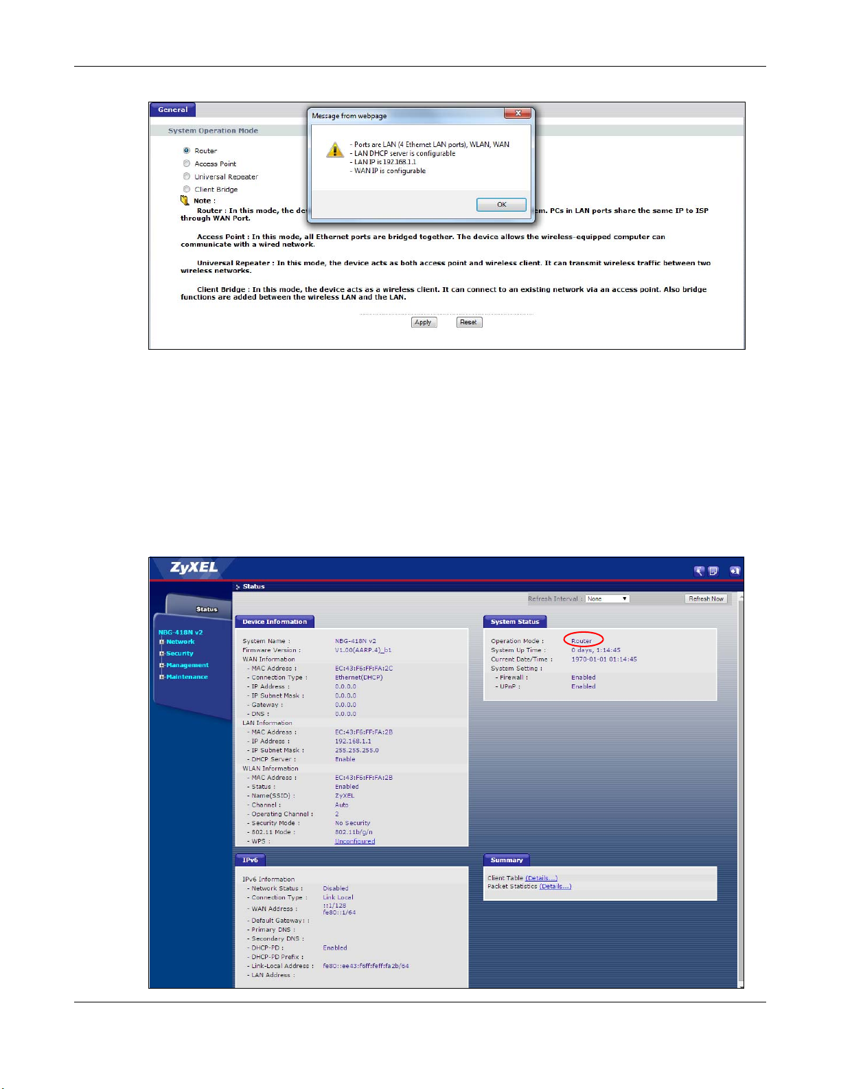
5 Go to Ma intena nc e > Sys O P Mode > G ene ra l and select Ro uter.
NBG-418N v2 User’s Guide
Chapter 2 on page 16 for instructions on how to do this.
29
Page 30
Chapter 4 Modes
6 A pop-up window appears providing information on this mode. Click O K in the pop-up message
window. Click Ap p ly.
Note: Wait while the NBG-418N v2 restarts, then log in to the Web Configurator again. The
NBG-418N v2 IP address is now 192.168.1.1.
4.2.1 Status Sc re e n (Route r Mode )
The screen below shows the status screen in Ro ute r mode.
Figure 21 Status Screen (Router Mode)
NBG-418N v2 User’s Guide
30
Page 31

Chapter 4 Modes
The following table describes the icons shown in the Sta tus screen.
Table 7 Status Screen Icon Key
IC ON DESCRIPTIO N
Click this icon to open the setup wizard.
Click this icon to view copyright and a link for related product information.
Click this icon at any time to exit the Web Configurator.
The following table describes the labels shown in the Sta tus screen in Router mode.
Table 8 Web Configurator Status Screen (Router Mode)
LABEL DESCRIPTIO N
Device Information
System Name This is the Syste m Na m e you enter in the Mainte nanc e > Syste m > Ge ne ra l screen.
It is for identification purposes.
Firmware Version This is the current firmware version of the NBG-418N v2.
WAN Information
- MAC Address This shows the WAN Ethernet adapter MAC Address of your device.
- Connection Type This shows the current connection type.
- IP Address This shows the WAN port’s IP address.
- IP Subnet Mask This shows the WAN port’s subnet mask.
- Gateway This shows the WAN port’s gateway IP address.
- DNS This shows the IP address of your DNS server.
LAN Information
- MAC Address This shows the LAN Ethernet adapter MAC Address of your device.
- IP Address This shows the LAN port’s IP address.
- IP Subnet Mask This shows the LAN port’s subnet mask.
- DHCP Server This shows the LAN port’s DHCP server status.
WLAN Information
- MAC Address This shows the wireless adapter MAC Address of your device.
- Status This shows the current status of the Wireless LAN - On, Off or O ff by sc heduler.
- Name (SSID) This shows a descriptive name used to identify the NBG-418N v2 in the wireless LAN.
- Channel This shows the channel number which you select manually or the NBG-418N v2
automatically scans and selects.
- Operating Channel This shows the channel number which the NBG-418N v2 is currently using over the
- Security Mode This shows the level of wireless security the NBG-418N v2 is using.
- 802.11 Mode This shows the wireless standard.
- WPS This displays Co nfigured when the WPS has been set up.
IPv6
Network Status This field displays the IPv6 network connection status.
wireless LAN.
This displays Unc onfig ured if the WPS has not been set up.
Click the status to display Ne two rk > Wireless LA N > WPS screen.
NBG-418N v2 User’s Guide
31
Page 32

Chapter 4 Modes
Table 8 Web Configurator Status Screen (Router Mode) (continued)
LABEL DESCRIPTIO N
Connection Type This field displays the IPv6 connection type that is currently in use.
WAN Address This field displays the current WAN IPv6 address of the NBG-418N v2.
Default Gateway This field displays the IPV6’s gateway address of the NBG-418N v2.
Primary DNS This field displays the IPV6’s primary DNS server’s address of the NBG-418N v2.
Secondary DNS This field displays the IPV6’s secondary DNS server’s address of the NBG-418N v2.
DHCP-PD This field displays the status of the IPv6 DHCP’s Prefix Delegation.
DHCP-PD Prefix This field displays the delegated IPv6 DHCP’s Prefixes.
Link-Local Address This field displays the link-local IP address of the NBG-418N v2 LAN port. A link-local
address is similar to a “private IP address” in IPv4. You can have the same link-local
address on multiple interfaces on a device.
LAN Address This field displays the IPv6 LAN’s IP address.
System Status
Operation Mode This field shows the device operation mode: Router, A c ce ss Point, Unive rsa l
System Up Time This is the total time the NBG-418N v2 has been on.
Current Date/Time This field displays your NBG-418N v2’s present
System Setting
- Firewall This shows whether the firewall is active or not.
- UPnP This shows whether UPnP is active or not.
Summary
Client Table Use this screen to view current client information. Click “Details...” to see the
Packet Statistics Use this screen to view port status and packet specific statistics. Click “De ta ils...” to
Re pe ater or Clie nt Bridg e .
date and time.
screen.
see the screen.
4.2.1.1 Summa ry: C lie nt Ta ble
Click the Clie nt Ta ble (De tails...) hyperlink in the Sta tus screen. The client table shows current client
information (including IP Ad d ress, Host Name and MAC Ad d ress) of all network clients connected to the
NBG-418N v2.
Figure 22 Summary: Client Table
NBG-418N v2 User’s Guide
32
Page 33

The following table describes the labels in this screen.
Table 9 Summary: Client Table
LABEL DESCRIPTIO N
# This is the index number of the host computer.
IP Address This field displays the IPv4 address relative to the # field listed above.
Host Name This field displays the computer host name.
MAC Address This field shows the MAC address of the computer with the name in the Host Name field.
Every Ethernet device has a unique MAC (Media Access Control) address which uniquely
identifies a device. The MAC address is assigned at the factory and consists of six pairs of
hexadecimal characters, for example, 00:A0:C5:00:00:02.
Interface This field shows the NBG-418N v2’s interface to which the client is connected.
IPv6 DHCP Table
# This is the index number of the IPv6 client table.
IPv6 Address This field displays the IPv6 address of the host computer.
Host Name This field displays the computer host name.
Refresh Click Re fre sh to renew the screen.
4.2.1.2 Summa ry: Pa c ket Sta tistic s
Chapter 4 Modes
Click the Pa cke t Sta tistic s (Details...) hyperlink in the Sta tus screen. Read-only information here includes
port status, packet specific statistics and the "system up time". The Po ll Interva l(s) field is configurable
and is used for refreshing the screen.
Figure 23 Summary: Packet Statistics
The following table describes the labels in this screen.
Table 10 Summary: Packet Statistics
LABEL DESCRIPTIO N
Port This is the NBG-418N v2’s port type.
RxPkts This is the number of received packets on this port.
Rx err This is the number of received packets with errors on this port.
Rx drop This is the number of received packets that were dropped on this port.
Txpkts This is the number of transmitted packets on this port.
Tx err This is the number of transmitted packets with errors on this port.
Tx drop This is the number of transmitted packets that were dropped on this port.
System Up Time This is the total time the NBG-418N v2 has been on.
NBG-418N v2 User’s Guide
33
Page 34

Chapter 4 Modes
Table 10 Summary: Packet Statistics (continued)
LABEL DESCRIPTION
Poll Interval(s) Enter the time interval for refreshing statistics in this field.
Set Interval Click this button to apply the new poll interval you entered in the Po ll Interva l(s) field.
Stop Click Sto p to stop refreshing statistics.
4.2.2 Route r Mo de Na vig ation Pa ne l
Use the menu in the navigation panel menus to configure NBG-418N v2 features in Router Mo de .
Figure 24 Menus: Router Mode
The following table describes the sub-menus.
Table 11 Menus: Router Mode
LINK TAB FUNCTION
Network
Wireless
LAN
General Use this screen to configure wireless LAN.
MAC Filter Use the MAC filter screen to configure the NBG-418N v2 to block access to
devices or block the devices from accessing the NBG-418N v2.
Advanced This screen allows you to configure advanced wireless settings.
WPS Use this screen to configure WPS.
WPS Station Use this screen to add a wireless station using WPS.
Scheduling Use this screen to schedule the times the Wireless LAN is enabled.
MBSSID Use this screen to configure multiple SSIDs on the NBG-418N v2.
NBG-418N v2 User’s Guide
34
Page 35

Chapter 4 Modes
Table 11 Menus: Router Mode (continued)
LINK TAB FUNCTION
WAN Internet
Connection
Advanced Use this screen to configure multicast WAN and auto IP setup.
IPv6 Use this screen to set the IPv6 WAN connection type, and LAN/WAN IPv6
LAN IP Use this screen to configure LAN IPv4 address and subnet mask.
DHCP
Server
NAT General Use this screen to enable NAT.
DDNS General Use this screen to configure Dynamic DNS, a service that allows you to map a
Static Route IP Static Route Use this screen to configure IP static routes.
Security
Firewall General Use this screen to activate/deactivate the firewall.
Content
Filter
Management
Remote
MGMT
UPnP General Use this screen to enable UPnP on the NBG-418N v2.
Bandwidth
MGMT
Maintenance
System General Use this screen to view and change administrative settings such as system and
Logs View Log Use this screen to view the logs for the categories that you selected.
Tools Firmware Use this screen to upload firmware to your NBG-418N v2.
Sys OP
Mode
Language Language This screen allows you to select the language you prefer.
General Use this screen to enable the NBG-418N v2’s DHCP server.
Advanced Use this screen to assign IP addresses to specific individual computers based
Client List Use this screen to view current DHCP client information and to always assign
Application Use this screen to configure servers behind the NBG-418N v2.
Port Triggering Use this screen to configure port triggering settings on the NBG-418N v2.
Services Use this screen to enable or disable ICMP and VPN passthrough features.
Filter Use this screen to configure content filter settings on the NBG-418N v2.
WWW Use this screen to configure through which interface(s) and from which IP
General Use this screen to enable bandwidth management on the NBG-418N v2.
Advanced Use this screen to set the upstream bandwidth and edit a bandwidth
Time Setting Use this screen to change your NBG-418N v2’s time and date.
Configuration Use this screen to backup and restore the configuration or reset the factory
Restart This screen allows you to reboot the NBG-418N v2 without turning the power
General This screen allows you to select the device operating mode.
This screen allows you to configure ISP parameters, WAN IP address
assignment, DNS servers and the WAN MAC address.
address settings.
on their MAC addresses and to have DNS servers assigned by the DHCP server.
an IP address to a MAC address (and host name).
fixed domain name to a non-fixed IP address.
address(es) users can use HTTP to manage the NBG-418N v2.
management rule.
domain names, password and inactivity timer.
defaults to your NBG-418N v2.
off.
NBG-418N v2 User’s Guide
35
Page 36

Chapter 4 Modes
4.3 Se tting your NBG-418N v2 to AP Mode
1 Connect your computer to the LAN port of the NBG-418N v2.
2 The default LAN IP address of the NBG-418N v2 is 192.168.1.1 in router mode and 192.168.1.2 by default in
non-router mode.
3 After you’ve set your computer’s IP address, open a web browser such as Internet Explorer and type the
IP address of the NBG-418N v2 as the web address in your web browser.
4 Log into the Web Configurator. See the
5 Go to Ma inte na nce > Sys OP Mode > G ene ra l and select Ac ce ss Point.
6 A pop-up window appears providing information on this mode. Click O K in the pop-up message
window. Click Ap p ly. Your NBG-418N v2 is now in AP Mode .
Chapter 2 on page 16 for instructions on how to do this.
Note: Wait while the NBG-418N v2 restarts, then log in to the Web Configurator again.
4.3.1 Status Sc re e n (AP Mo de )
Click on Sta tus. The screen below shows the status screen in AP Mode .
NBG-418N v2 User’s Guide
36
Page 37

Figure 25 Status Screen (AP Mode)
Chapter 4 Modes
The following table describes the labels shown in the Sta tus screen.
Table 12 Status Screen (AP Mode)
LABEL DESCRIPTIO N
Device Information
System Name This is the Syste m Na me you enter in the Mainte na nce > System > Ge nera l screen. It is for
Firmware Version This is the current firmware version of the NBG-418N v2.
LAN Information
- MAC Address This shows the LAN Ethernet adapter MAC Address of your device.
- IP Address This shows the LAN port’s IP address.
- IP Subnet Mask This shows the LAN port’s subnet mask.
- DHCP Server This shows the LAN port’s DHCP server status.
WLAN Information
- MAC Address This shows the wireless adapter MAC Address of your device.
- Status This shows the current status of the Wireless LAN - O n, O ff, or Off by sc hed ule r.
- Name (SSID) This shows a descriptive name used to identify the NBG-418N v2 in the wireless LAN.
- Channel This shows the channel number which you select manually or the NBG-418N v2
- Operating Channel This shows the channel number which the NBG-418N v2 is currently using over the
- Security Mode This shows the level of wireless security the NBG-418N v2 is using.
- 802.11 Mode This shows the IEEE 802.11 standard that the NBG-418N v2 supports. Wireless clients must
- WPS This shows the WPS (WiFi Protected Setup) Status. Click the status to display Ne two rk >
System Status
identification purposes.
automatically scans and selects.
wireless LAN.
support the same standard in order to be able to connect to the NBG-418N v2
Wire le ss LAN > WPS screen.
NBG-418N v2 User’s Guide
37
Page 38

Table 12 Status Screen (AP Mode) (continued)
LABEL DESCRIPTIO N
Operation Mode This field shows the device operatiing mode: Router, Ac ce ss Po int, Universa l Rep ea te r or
Clie nt Bridg e .
System Up Time This is the total time the NBG-418N v2 has been on.
Current Date/Time This field displays your NBG-418N v2’s present
Summary
Client Table Use this screen to view current client information. Click “Details...” to see the screen.
Packet Statistics Use this screen to view port status and packet specific statistics. Click “Details...” to see
the screen.
4.3.2 AP Na vig atio n Pa nel
Use the menu in the navigation panel to configure NBG-418N v2 features in AP Mode .
The following screen and table show the features you can configure in AP Mode .
Figure 26 Menu: AP Mode
Chapter 4 Modes
date and time.
The following table describes the sub-menus.
Table 13 Menu: AP Mode
LINK TAB FUNCTIO N
Network
Wireless LAN General Use this screen to configure wireless LAN.
MAC Filter Use the MAC filter screen to configure the NBG-418N v2 to block access to
devices or block the devices from accessing the NBG-418N v2.
Advanced This screen allows you to configure advanced wireless settings.
WPS Use this screen to configure WPS.
WPS Station Use this screen to add a wireless station using WPS.
Scheduling Use this screen to schedule the times the Wireless LAN is enabled.
MBSSID Use this screen to configure multiple SSIDs on the NBG-418N v2.
LAN IP Use this screen to configure LAN IP address and subnet mask.
Maintenance
System General Use this screen to view and change administrative settings such as system
and domain names, password and inactivity timer.
Time Setting Use this screen to change your NBG-418N v2’s time and date.
Logs View Log Use this screen to view the logs for the categories that you selected.
NBG-418N v2 User’s Guide
38
Page 39

Chapter 4 Modes
Table 13 Menu: AP Mode (continued)
LINK TAB FUNCTIO N
Tools Firmware Use this screen to upload firmware to your NBG-418N v2.
Configuration Use this screen to backup and restore the configuration or reset the factory
defaults to your NBG-418N v2.
Restart This screen allows you to reboot the NBG-418N v2 without turning the power
off.
Sys OP Mode General This screen allows you to select the device operating mode: Router, A c ce ss
Language Language This screen allows you to select the language you prefer.
Point, Unive rsa l Re p e ate r or Clie nt Bridg e .
4.4 Se tting your NBG-418N v2 to Unive rsal Repe a te r Mode
1 Connect your computer to the LAN port of the NBG-418N v2.
2 The default LAN IP address of the NBG-418N v2 is 192.168.1.1 in router mode and 192.168.1.2 by default in
non-router mode.
3 After you’ve set your computer’s IP address, open a web browser such as Internet Explorer and type the
IP address of the NBG-418N v2 as the web address in your web browser.
4 Log into the Web Configurator. See the
5 Go to Ma inte na nce > Sys OP Mode > G ene ra l and select Unive rsa l Re p e ater.
6 A pop-up window appears providing information on this mode. Click O K in the pop-up message
window. Click Ap p ly. Your NBG-418N v2 is now in Unive rsal Re pe a ter mode.
Chapter 2 on page 16 for instructions on how to do this.
Note: Wait while the NBG-418N v2 restarts, then log in to the Web Configurator again.
4.4.1 Status Sc re e n (Unive rsa l Repe a te r Mode )
Click on Sta tus. The screen below shows the status screen in Unive rsa l Re p e ater mode.
NBG-418N v2 User’s Guide
39
Page 40

Chapter 4 Modes
Figure 27 Status Screen (Universal Repeater Mode)
The following table describes the labels shown in the Sta tus screen.
Table 14 Status Screen (Universal Repeater Mode)
LABEL DESCRIPTIO N
Device Information
System Name This is the Syste m Na m e you enter in the Mainte nanc e > Syste m > Ge ne ra l screen.
It is for identification purposes.
Firmware Version This is the current firmware version of the NBG-418N v2.
LAN Information
- MAC Address This shows the LAN Ethernet adapter MAC Address of your device.
- IP Address This shows the LAN port’s IP address.
- IP Subnet Mask This shows the LAN port’s subnet mask.
- DHCP Server This shows the LAN port’s DHCP server.
WLAN AP Information
- MAC Address This shows the wireless adapter MAC Address of your device.
- Status This shows the current status of the Wireless LAN - On, Off, or Off by sc heduler.
- Name (SSID) This shows a descriptive SSID name used to identify the NBG-418N v2 in the wireless
LAN.
- Channel This shows the channel number which you select manually or the NBG-418N v2
- Operating Channel This shows the channel number which the NBG-418N v2 is currently using over the
- Security Mode This shows the level of wireless security the NBG-418N v2 is using.
- 802.11 Mode This shows the IEEE 802.11 standard that the NBG-418N v2 supports. Wireless clients
automatically scans and selects.
wireless LAN.
must support the same standard in order to be able to connect to the NBG-418N
v2
NBG-418N v2 User’s Guide
40
Page 41

Chapter 4 Modes
Table 14 Status Screen (Universal Repeater Mode) (continued)
LABEL DESCRIPTIO N
- WPS This shows the WPS (WiFi Protected Setup) Status. Click the link to display Ne two rk >
Wire le ss LAN > WPS screen.
WLAN STA Information
- SSID This is the name of the selected AP that the NBG-418N v2 is associating with.
- Security Mode This shows the wireless security the NBG-418N v2 is using to connect to the AP.
- Connection Status This shows whether the NBG-418N v2 is currently associated with the selected AP.
System Status
Operation Mode This field shows the device operating mode: Router, A c c e ss Po int, Universa l
Re pe ater or Clie nt Bridg e .
System Up Time This is the total time the NBG-418N v2 has been on.
Current Date/Time This field displays your NBG-418N v2’s present
Summary
Client table Use this screen to view current client information. Click “De ta ils...” to see the
screen.
Packet Statistics Use this screen to view port status and packet specific statistics. Click “De ta ils...” to
see the screen.
Message Use this screen to view the status of the NBG-418N v2.
date and time.
4.4.2 Unive rsa l Re pe a te r Na vig ation Pa ne l
Use the menu in the navigation panel to configure NBG-418N v2 features in Unive rsal Re pe a te r Mo de .
The following screen and table show the features you can configure in Unive rsal Re pe a ter Mode .
Figure 28 Menu: Universal Repeater Mode
The following table describes the sub-menus.
Table 15 Menu: Universal Repeater Mode
LINK TAB FUNCTIO N
Status This screen shows the NBG-418N v2’s general device, system and interface
status information. Use this screen to access the wizard, and summary
statistics tables.
Network
NBG-418N v2 User’s Guide
41
Page 42

Chapter 4 Modes
Table 15 Menu: Universal Repeater Mode (continued)
LINK TAB FUNCTIO N
WLAN AP Select Use this screen to choose an access point that you want the NBG-418N v2 to
connect to. You should know the security settings of the target AP.
General Use this screen to configure wireless LAN.
MAC Filter Use the MAC filter screen to configure the NBG-418N v2 to block access to
devices or block the devices from accessing the NBG-418N v2.
Advanced This screen allows you to configure advanced wireless settings.
WPS Use this screen to configure WPS.
WPS Station Use this screen to add a wireless station using WPS.
Scheduling Use this screen to schedule the times the Wireless LAN is enabled.
MBSSID Use this screen to configure multiple SSIDs on the NBG-418N v2.
LAN IP Use this screen to configure LAN IP address and subnet mask.
Maintenance
System General Use this screen to view and change administrative settings such as system
Time Setting Use this screen to change your NBG-418N v2’s time and date.
Logs View Log Use this screen to view the logs for the categories that you selected.
Tools Firmware Use this screen to upload firmware to your NBG-418N v2.
Configuration Use this screen to backup and restore the configuration or reset the factory
Restart This screen allows you to reboot the NBG-418N v2 without turning the power
Sys OP Mode General This screen allows you to select the device operating mode: Router, A c ce ss
Language Language This screen allows you to select the language you prefer.
and domain names, password and inactivity timer.
defaults to your NBG-418N v2.
off.
Point, Unive rsa l Re p e ate r or Clie nt Bridg e .
4.5 Se tting your NBG-418N v2 to C lie nt Bridge Mo de
1 Connect your computer to the LAN port of the NBG-418N v2.
2 The default LAN IP address of the NBG-418N v2 is 192.168.1.1 in router mode and 192.168.1.2 by default in
non-router mode.
3 After you’ve set your computer’s IP address, open a web browser such as Internet Explorer and type the
IP address of the NBG-418N v2 as the web address in your web browser.
4 Log into the Web Configurator. See the
5 Go to Ma inte na nce > Sys OP Mode > G ene ra l and select C lie nt Brid g e.
NBG-418N v2 User’s Guide
Chapter 2 on page 16 for instructions on how to do this.
42
Page 43

Chapter 4 Modes
6 A pop-up window appears providing information on this mode. Click O K in the pop-up message
window. Click Ap p ly. Your NBG-418N v2 is now in C lie nt Bridg e mode.
Note: Wait while the NBG-418N v2 restarts, then log in to the Web Configurator again.
4.5.1 Status Sc re e n (Clie nt Bridg e Mo de )
Click on Sta tus. The screen below shows the status screen in Clie nt Brid g e mode.
Figure 29 Status Screen (Client Bridge Mode)
The following table describes the labels shown in the Sta tus screen.
Table 16 Status Screen (Client Bridge Mode)
LABEL DESCRIPTIO N
Device Information
System Name This is the Syste m Na m e you enter in the Mainte nanc e > Syste m > Ge ne ra l screen.
It is for identification purposes.
NBG-418N v2 User’s Guide
43
Page 44

Chapter 4 Modes
Table 16 Status Screen (Client Bridge Mode) (continued)
LABEL DESCRIPTIO N
Firmware Version This is the current firmware version of the NBG-418N v2.
LAN Information
- MAC Address This shows the LAN Ethernet adapter MAC Address of your device.
- IP Address This shows the LAN port’s IP address.
- IP Subnet Mask This shows the LAN port’s subnet mask.
- DHCP Server This shows the status of the LAN port’s DHCP server.
WLAN STA Information
- SSID This is the name of the selected AP that the NBG-418N v2 is associating with.
- Security Mode This shows the wireless security the NBG-418N v2 is using to connect to the AP.
- Connection Status This shows whether the NBG-418N v2 is currently associated with the selected AP.
System Status
Operation Mode This field shows the device operating mode: Router, A c c e ss Po int, Universa l
Re pe ater or Clie nt Bridg e .
System Up Time This is the total time the NBG-418N v2 has been on.
Current Date/Time This field displays your NBG-418N v2’s present
Summary
Client Table Use this screen to view information of the client that is currently connected to the
NBG-418N v2’s Ethernet LAN port.
Packet Statistics Use this screen to view port status and packet specific statistics.
date and time.
4.5.2 Unive rsa l Re pe a te r Na vig ation Pa ne l
Use the menu in the navigation panel to configure NBG-418N v2 features in Clie nt Bridg e Mo de .
The following screen and table show the features you can configure in C lie nt Bridg e Mode .
Figure 30 Menu: Client Bridge Mode
NBG-418N v2 User’s Guide
44
Page 45

Chapter 4 Modes
The following table describes the sub-menus.
Table 17 Menu: Client Bridge Mode
LINK TAB FUNCTIO N
Status This screen shows the NBG-418N v2’s general device, system and interface
Network
AP Select AP Select Use this screen to choose an access point that you want the NBG-418N v2 to
WLAN
Information
Advanced This screen allows you to configure advanced wireless settings.
LAN IP Use this screen to configure LAN IP address and subnet mask.
Maintenance
System General Use this screen to view and change administrative settings such as system
Time Setting Use this screen to change your NBG-418N v2’s time and date.
Logs View Log Use this screen to view the logs for the categories that you selected.
Tools Firmware Use this screen to upload firmware to your NBG-418N v2.
Configuration Use this screen to backup and restore the configuration or reset the factory
Restart This screen allows you to reboot the NBG-418N v2 without turning the power
Sys OP Mode General This screen allows you to select the device operating mode: Router, A c ce ss
Language Language This screen allows you to select the language you prefer.
status information. Use this screen to access the wizard, and summary
statistics tables.
connect to. You should know the security settings of the target AP.
Use this screen to view the SSID and security mode of the AP to which the
NBG-418N v2 is connecting.
and domain names, password and inactivity timer.
defaults to your NBG-418N v2.
off.
Point, Unive rsa l Re pe ate r or Clie nt Bridg e .
NBG-418N v2 User’s Guide
45
Page 46

C HAPTER 5
AP
B
Tutoria ls
5.1 O ve rvie w
This chapter provides tutorials for your NBG-418N v2 as follows:
•
How to Connect to the Internet from an AP
• Configure Wireless Security Using WPS on both your NBG-418N v2 and Wireless Client
• Enable and Configure Wireless Security without WPS on your NBG-418N v2
• Using Multiple SSIDs on the NBG-418N v2
•
Using Bandwidth Management on the NBG-418N v2
5.2 Ho w to C onne c t to the Inte rne t from a n AP
This section gives you an example of how to set up an access point (AP) and wireless client (a notebook,
B in this example) for wireless communication. B can access the Internet through the AP wirelessly.
Figure 31 Wireless AP Connection to the Internet
5.3 Config ure Wirele ss Se c urity Using WPS on bo th yo ur NBG-418N v2 a nd Wirele ss Clie nt
This section gives you an example of how to set up wireless network using WPS. This example uses the
NBG-418N v2 as the AP and NWD210N as the wireless client which connects to a notebook.
Note: The wireless client must be a WPS-aware device (for example, a WPS USB adapter or
PCI card).
There are two WPS methods for creating a secure connection. This tutorial shows you how to do both.
• Push Butto n Co nfiguration (PBC) - create a secure wireless network simply by pressing a button. See
Section 5.3.1 on page 47.This is the easier method.
NBG-418N v2 User’s Guide
46
Page 47

Chapter 5 Tutorials
• PIN Config ura tion - create a secure wireless network simply by entering a wireless client's PIN (Personal
Identification Number) in the NBG-418N v2’s interface. See
secure method, since one device can authenticate the other.
5.3.1 Push Button Configura tion (PBC )
1 Make sure that your NBG-418N v2 is turned on and that it is within range of your computer.
2 Make sure that you have installed the wireless client (this example uses the NWD210N) driver and utility in
your notebook.
3 In the wireless client utility, find the WPS settings. Enable WPS and press the WPS button (Start or WPS
button)
4 Log into NBG-418N v2’s Web Configurator and press Push Butto n in the Ne twork > Wire less LAN > WPS
Sta tio n screen.
Note: Your NBG-418N v2 has a WPS/RESET button located on its back panel, as well as a WPS
button in its configuration utility. Both buttons have exactly the same function; you can
use one or the other.
Section 5.3.2 on page 48. This is the more
Note: It doesn’t matter which button is pressed first. You must press the second button within
two minutes of pressing the first one.
The NBG-418N v2 sends the proper configuration settings to the wireless client. This may take up to two
minutes. Then the wireless client is able to communicate with the NBG-418N v2 securely.
The following figure shows you an example to set up wireless network and security by pressing a button
on both NBG-418N v2 and wireless client (the NWD210N in this example).
NBG-418N v2 User’s Guide
47
Page 48

Chapter 5 Tutorials
Wireless Client
NBG-418N v2
SECURITY INFO
COMMUNICATION
WITHIN 2 MINUTES
WPS/ Reset
Figure 32 Example WPS Process: PBC Method
5.3.2 PIN C o nfig ura tion
When you use the PIN configuration method, you need to use both NBG-418N v2’s configuration
interface and the client’s utilities.
1 Launch your wireless client’s configuration utility. Go to the WPS settings and select the PIN method to
get a PIN number.
2 Enter the PIN number to the PIN field in the Ne twork > Wireless LAN > WPS Station screen on the NBG-
418N v2.
3 Click the Sta rt buttons (or button next to the PIN field) on both the wireless client utility screen and the
NBG-418N v2’s WPS Sta tion screen within two minutes.
The NBG-418N v2 authenticates the wireless client and sends the proper configuration settings to the
wireless client. This may take up to two minutes. Then the wireless client is able to communicate with the
NBG-418N v2 securely.
The following figure shows you the example to set up wireless network and security on NBG-418N v2 and
wireless client (ex. NWD210N in this example) by using PIN method.
NBG-418N v2 User’s Guide
48
Page 49

Chapter 5 Tutorials
Authentication by PIN
SECURITY INFO
WITHIN 2 MINUTES
Wireless Client
NBG-418N v2
COMMUNICATION
Figure 33 Example WPS Process: PIN Method
NBG-418N v2 User’s Guide
49
Page 50

Chapter 5 Tutorials
5.4 Ena ble a nd Config ure Wirele ss Se c urity without WPS on yo ur NBG - 418N v2
This example shows you how to configure wireless security settings with the following parameters on your
NBG-418N v2.
SSID SSID_Example3
Cha nne l 6
Sec urity WPA-PSK
(Pre-Shared Key: ThisismyWPA-PSKpre-sharedkey)
Follow the steps below to configure the wireless settings on your NBG-418N v2.
The instructions require that your hardware is connected (see the Quick Start Guide) and you are
logged into the Web Configurator through your LAN connection (see
1 Open the Wire less LAN > Ge ne ral screen in the NBG-418N v2’s Web Configurator.
2 Make sure the Ena ble Wireless LA N check box is selected.
Section 2.2 on page 16).
3 Enter SSID_Exa m ple3 as the SSID and select a channel.
4 Set security mode to WPA- PSK(A ES) and enter ThisismyWPA- PSKpre - sha redke y in the Pre- Share d Ke y
field. Click Ap p ly.
Figure 34 Tutorial: Network > Wireless LAN > General
5 Open the Sta tus screen. Verify your wireless and wireless security settings under De vice Informa tio n and
check if the WLAN connection is up under Interfac e Sta tus.
NBG-418N v2 User’s Guide
50
Page 51

Figure 35 Tutorial: Status Screen
Chapter 5 Tutorials
5.4.1 Config ure Your Wire le ss C lie nt
Note: We use the Zyxel M-302 wireless adapter utility screens as an example for the wireless
client. The screens may vary for different models.
1 The NBG-418N v2 supports IEEE 802.11b, IEEE 802.11g and IEEE 802.11n wireless clients. Make sure that
your notebook or computer’s wireless adapter supports one of these standards.
2 Wireless adapters come with software sometimes called a “utility” that you install on your computer. See
your wireless adapter’s User’s Guide for information on how to do that.
3 After you’ve installed the utility, open it. If you cannot see your utility’s icon on your screen, go to Sta rt >
Prog ra ms and click on your utility in the list of programs that appears. The utility displays a list of APs
within range, as shown in the example screen below.
4 Select SSID_Exa mple3 and click Co nne ct.
NBG-418N v2 User’s Guide
51
Page 52

Chapter 5 Tutorials
Figure 36 Connecting a Wireless Client to a Wireless Network t
5 Select WPA2-PSK and type the security key in the following screen. Click Next.
Figure 37 Security Settings
6 The Co nfirm Save window appears. Check your settings and click Save to continue.
Figure 38 Confirm Save
7 Check the status of your wireless connection in the screen below. If your wireless connection is weak or
you have no connection, see the
Troubleshooting section of this User’s Guide.
NBG-418N v2 User’s Guide
52
Page 53

Figure 39 Link Status
Chapter 5 Tutorials
If your connection is successful, open your Internet browser and enter
of any other web site in the address bar. If you are able to access the web site, your wireless connection
is successfully configured.
http://www.zyxel.com or the URL
5.5 Using Multiple SSIDs on the NBG-418N v2
You can configure more than one SSID on a NBG-418N v2. See
This allows you to configure multiple independent wireless networks on the NBG-418N v2 as if there were
multiple APs (virtual APs). Each virtual AP has its own SSID, and wireless security type. That is, each SSID on
the NBG-418N v2 represents a different access point/wireless network to wireless clients in the network.
Clients can associate only with the SSIDs for which they have the correct security settings. Clients using
different SSIDs can access the Internet and the wired network behind the NBG-418N v2 (such as a
printer).
Section 6.10 on page 72.
NBG-418N v2 User’s Guide
53
Page 54

Chapter 5 Tutorials
A
B
C
SSI D_ Gue st
SSI D_ W or k e rs
SSI D_ V oI P
For example, you may set up three wireless networks (A, B and C) in your office. A is for workers, B is for
guests and C is specific to a VoIP device in the meeting room.
5.5.1 Configuring Sec urity Settings o f Multiple SSIDs
The NBG-418N v2 is in router mode by default.
This example shows you how to configure the SSIDs with the following parameters on your NBG-418N v2
(in router mode).
SSID SECURITY TYPE KEY
SSID_Workers WPA2-PSK
WPA Compatible
SSID_VoIP WPA-PSK VoIPOnly12345678
SSID_Guest WPA-PSK keyexample123
1 Connect your computer to the LAN port of the NBG-418N v2 using an Ethernet cable.
2 The default IP address of the NBG-418N v2 in router mode is “192.168.1.1”. In this case, your computer
must have an IP address in the range between “192.168.1.2” and “192.168.1.254”.
3 Click Start > Run on your computer in Windows. Type “cmd” in the dialog box. Enter “ipconfig” to show
your computer’s IP address. If your computer’s IP address is not in the correct range then see
D on page 178 for information on changing your computer’s IP address.
4 After you’ve set your computer’s IP address, open a web browser such as Internet Explorer and type
“http://192.168.1.1” as the web address in your web browser.
5 Enter “1234” (default) as the password and click Log in.
DoNotStealMyWirelessNetwork
Appendix
6 Type a new password and retype it to confirm, then click Apply. Otherwise, click Ig nore.
NBG-418N v2 User’s Guide
54
Page 55

Chapter 5 Tutorials
7 A window appears asking you to select Wizard or Advance mode. Click G o to Adva nce d Setup in the
navigation panel.
8 Go to Ne two rk > Wire less LAN > MBSSID. Type SSID_Worke rs in the Name (SSID) field, select WPA2-
PSK(A ES) in the Security drop-down list, enter the pre-share key and click Apply.
9 Go to Ne two rk > Wire less LAN > Adva nc e d and click enable Intra - BSS Tra ffic to allow wireless clients in
the same wireless network to communicate with each other. Click A p ply.
10 To create the SSID_VoIP, go to Ne twork > Wireless LA N > MBSSID. click the radio button next to sc hem e 2
and Type SSID_Vo ip in the Name (SSID) field, select WPA -PSK in the Security drop-down list, enter the pre-
share key and click Ap p ly.
NBG-418N v2 User’s Guide
55
Page 56

Chapter 5 Tutorials
11 To create the SSID_Guest, go to Ne two rk > Wireless LAN > MBSSID. click the radio button next to sc he m e
3 and Type SSID_G ue st in the Name (SSID) field, click Enab le Wire less Isolatio n if you do not want the
SSID_Guest wireless clients to communicate with each other. select WPA- PSK in the Security drop-down
list, enter the pre-share key and click Apply.
NBG-418N v2 User’s Guide
56
Page 57

Chapter 5 Tutorials
A
B
-> VoIP
-> FTP
-> HTTP
-> Chat, E-QoSmail
5.6 Insta lling UPnP in Windows 7 Exa mple
For more information on how to install Universal Plug and Play in Windows on your computer, see
16.4 on page 126
Section
5.7 Using Ba ndwidth Ma na geme nt o n the NBG-418N v2
Bandwidth management provides a convenient way to manage the use of various services on the
network. It manages general protocols (for example, HTTP and FTP) and applies traffic prioritization to
enhance the performance of delay-sensitive applications like voice and video.
In the figure below, uplink traffic goes from the LAN device (A ) to the WAN device (B). Bandwidth
management is applied before sending the packets out to the WAN. Downlink traffic comes back from
the WAN device (B) to the LAN device (A). Bandwidth management is applied before sending the
traffic out to LAN.
Figure 40 Bandwidth Management Example
You can allocate specific amounts of bandwidth capacity (bandwidth budgets) to individual
applications (like VoIP, Web, FTP, and E-mail for example).
This example shows you how to configure the Bandwidth Management with the following parameters
on your NBG-418N v2 (in router mode).
Qo S Rule
UP Stream 819200 kpbs
Down Stream 819200 kbps
Source IP 192.168.1.10
Up Ceiling 150000 kb/s
Down Ceiling 600000 kb/s
1 Go to Ma nage me nt > Ba nd width MG MT > Bandwidth MG MT and click Enable Bandwidth Management
check box.
NBG-418N v2 User’s Guide
57
Page 58

Chapter 5 Tutorials
2 Go to Ma nag em ent > Bandwidth MG MT > Adva nce d and enter 819200 in the Total Up Stre a m and Down
Stre a m Bandwidth fields in the Qo S Setup section. It is recommended to set this number to match the
actual upstream data rate. Click Apply or Rese t to clear the fields.
3 Then, Click Add in the Qo S Rules section and several box fields appears. Enter 192.168.1.10 in the Sourc e
IP fie ld , 192.168.1.10/32 will appear in the field, the 32-bits network is IPv4 addresses block that is assigned
by your ISP. Next, enter 150000 for Up C e ling field and 600000 for Do wn C e iling field and click Add. Note
that the Up/Down Ceiling numbers should not exceed the Total Bandwidth. You have successfully set a
specific minimum and maximum bandwidth for this particular IP address.
4 If you wish to delete a QoS Rules entry, click the Delete check box of the rule and click De le te button. To
clear the Source IP, Up/Down Ceiling box fields, click Re se t button.
NBG-418N v2 User’s Guide
58
Page 59

PART II
Te c hnic a l Re fe re nc e
59
Page 60

6.1 O ve rvie w
This chapter discusses how to configure the wireless network settings in your NBG-418N v2. See the
appendices for more detailed information about wireless networks.
The following figure provides an example of a wireless network.
Figure 41 Example of a Wireless Network
C HAPTER 6
Wire le ss LAN
The wireless network is the part in the blue circle. In this wireless network, devices A and B are called
wireless clients. The wireless clients use the access point (AP) to interact with other devices (such as the
printer) or with the Internet. Your NBG-418N v2 is the AP in the above example.
NBG-418N v2 User’s Guide
60
Page 61

6.2 Wha t Yo u C an Do
Wireless screens vary according to the device mode you are using.
Wireless Screen Router Access Point Universal Repeater Client Bridge
General
Chapter 6 Wireless LAN
MAC Filter
Advanced
WPS
WPS Station
Scheduling
MBSSID
AP Select
WLAN Information
See
Chapter 4 on page 28 for more information on device modes.
• Use the Ge ne ral screen to enable the Wireless LAN, enter the SSID and select the wireless security
mode (
• Use the MAC Filter screen to allow or deny wireless stations based on their MAC addresses from
connecting to the NBG-418N v2 (Section 6.5 on page 68).
• Use the Adva nce d screen to allow intra-BSS networking and set the RTS/CTS Threshold (
page 69
• Use the WPS screen to quickly set up a wireless network with strong security, without having to
configure security settings manually (Section 6.7 on page 69).
• Use the WPS Sta tion screen to add a wireless station using WPS (
• Use the Sc he d uling screen to set the times your wireless LAN is turned on and off (
71
• Use the MBSSID screen to configure multiple wireless networks on the NBG-418N v2 (
page 72
• Use the AP Se le c t screen to choose an access point that you want the NBG-418N v2 (in universal
repeater mode) to connect to. You should know the security settings of the target AP (Section 6.11 on
page 73
• Use the WLAN Info rm a tion screen to view the SSID and security of the selected AP wireless network
(Section 6.12 on page 74).
Section 6.4 on page 63).
).
).
).
).
Section 6.6 on
Section 6.8 on page 70).
Section 6.9 on page
Section 6.10 on
NBG-418N v2 User’s Guide
61
Page 62

Chapter 6 Wireless LAN
6.3 Wha t Yo u Should Kno w
Every wireless network must follow these basic guidelines.
• Every wireless client in the same wireless network must use the same SSID.
The SSID is the name of the wireless network. It stands for Service Set IDentity.
• If two wireless networks overlap, they should use different channels.
Like radio stations or television channels, each wireless network uses a specific channel, or frequency,
to send and receive information.
• Every wireless client in the same wireless network must use security compatible with the AP.
Security stops unauthorized devices from using the wireless network. It can also protect the
information that is sent in the wireless network.
6.3.1 Wire le ss Sec urity O ve rvie w
The following sections introduce different types of wireless security you can set up in the wireless
network.
6.3.2 MBSSID
Traditionally, you need to use different APs to configure different Basic Service Sets (BSSs). As well as the
cost of buying extra APs, there is also the possibility of channel interference. The NBG-418N v2’s MBSSID
(Multiple Basic Service Set IDentifier) function allows you to use one access point to provide several BSSs
simultaneously. You can then assign varying security modes to different SSIDs.
Wireless devices can use different BSSIDs to associate with the same AP.
6.3.2.1 Note s on Multip le BSSs
• A maximum of eight BSSs are allowed on one AP simultaneously.
• You must use different keys for different BSSs. If two wireless devices have different BSSIDs (they are in
different BSSs), but have the same keys, they may hear each other’s communications (but not
communicate with each other).
• MBSSID should not replace but rather be used in conjunction with 802.1x security.
6.3.3 MAC Address Filter
Every wireless client has a unique identification number, called a MAC address.1 A MAC address is
usually written using twelve hexadecimal characters
To get the MAC address for each wireless client, see the appropriate User’s Guide or other
documentation.
2
; for example, 00A0C5000002 or 00:A0:C5:00:00:02.
You can use the MAC address filter to tell the AP which wireless clients are allowed or not allowed to use
the wireless network. If a wireless client is allowed to use the wireless network, it still has to have the
correct settings (SSID, channel, and security). If a wireless client is not allowed to use the wireless
network, it does not matter if it has the correct settings.
1. Some wireless devices, such as scanners, can detect wireless networks but cannot use wireless networks. These
kinds of wireless devices might not have MAC addresses.
2. Hexadecimal characters are 0, 1, 2, 3, 4, 5, 6, 7, 8, 9, A, B, C, D, E, and F.
NBG-418N v2 User’s Guide
62
Page 63

This type of security does not protect the information that is sent in the wireless network. Furthermore,
there are ways for unauthorized devices to get the MAC address of an authorized wireless client. Then,
they can use that MAC address to use the wireless network.
6.3.4 Enc ryption
Wireless networks can use encryption to protect the information that is sent in the wireless network.
Encryption is like a secret code. If you do not know the secret code, you cannot understand the
message.
Table 18 Types of Encryption for Each Type of Authentication
We ake st No Security
Strong e st WPA2-PSK
For example, if users do not log in to the wireless network, you can choose no encryption, WEP, WPA-PSK,
or WPA2-PSK.
Chapter 6 Wireless LAN
NO AUTHENTIC ATIO N
Static WEP
WPA-PSK
Usually, you should set up the strongest encryption that every wireless client in the wireless network
supports. Suppose the wireless network has two wireless clients. Device A only supports WEP, and device
B supports WEP and WPA2-PSK. Therefore, you should set up WEP in the wireless network.
Note: It is recommended that wireless networks use WPA2-PSK, or stronger encryption. IEEE
802.1x and WEP encryption are better than none at all, but it is still possible for
unauthorized devices to figure out the original information pretty quickly.
Many types of encryption use a key to protect the information in the wireless network. The longer the
key, the stronger the encryption. Every wireless client in the wireless network must have the same key.
6.3.5 WPS
WiFi Protected Setup (WPS) is an industry standard specification, defined by the WiFi Alliance. WPS
allows you to quickly set up a wireless network with strong security, without having to configure security
settings manually. Depending on the devices in your network, you can either press a button (on the
device itself, or in its configuration utility) or enter a PIN (Personal Identification Number) in the devices.
Then, they connect and set up a secure network by themselves. See how to set up a secure wireless
network using WPS in the
Section 5.3 on page 46.
6.4 G e ne ra l Wire le ss LAN Scre e n
Use this screen to enable the Wireless LAN, enter the SSID and select the wireless security mode.
Note: If you are configuring the NBG-418N v2 from a computer connected to the wireless LAN
and you change the NBG-418N v2’s SSID, channel or security settings, you will lose your
wireless connection when you press Apply to confirm. You must then change the
wireless settings of your computer to match the NBG-418N v2’s new settings.
NBG-418N v2 User’s Guide
63
Page 64

Chapter 6 Wireless LAN
Click Ne two rk > Wire le ss LAN to open the G e ne ra l screen.
Figure 42 Network > Wireless LAN > General (Router or Access Point Mode)
Figure 43 Network > Wireless LAN > General (Universal Repeater Mode)
The following table describes the general wireless LAN labels in this screen.
Table 19 Network > Wireless LAN > General
LABEL DESCRIPTIO N
WLAN STA
Information
SSID This displays the Service Set IDentity of the wireless device to which you are connecting.
Security Mode This displays the type of security configured on the wireless device to which you are connecting.
Operating
Channel
This section is available only when the NBG-418N v2 is in universal repeater mode. This shows the
wireless and security settings of the selected AP wireless network.
This displays the channel used by the wireless device to which you are connecting.
NBG-418N v2 User’s Guide
64
Page 65

Chapter 6 Wireless LAN
Table 19 Network > Wireless LAN > General (continued)
LABEL DESCRIPTIO N
WLAN AP
Information /
Wireless Setup
Enable Wireless
LAN
802.11 Mode Click the drop-down list to choose the 802.11 m od e you want to operate.
Name(SSID) (Service Set IDentity) The SSID identifies the Service Set with which a wireless station is associated.
Enable SSID
Broadcast
Channel
Selection
Use this section to configure the wireless settings between the NBG-418N v2and its wireless clients.
Click the check box to activate wireless LAN.
Wireless stations associating to the access point (AP) must have the same SSID. Enter a
descriptive name (up to 32 printable 7-bit ASCII characters) for the wireless LAN.
Select the Ena b le SSID Broa dc ast check box to enable the SSID in the outgoing beacon frame so
a station cannot obtain the SSID through scanning using a site survey tool.
Set the operating frequency/channel depending on your particular region.
Select a channel from the drop-down list box. The options vary depending on the frequency
band and the country you are in.
Operating
Channel
Channel Width Select whether the NBG-418N v2 uses a wireless channel width of 20MHz, 40MHz or Auto 20/
Security Use this section to configure the wireless security between the NBG-418N v2 and its wireless
Security Mode Select WEP, WPA - PSK(TKIP), WPA- PSK(AES), WPA2-PSK(TKIP), WPA2- PSK(A ES) or WPA- PSK/ WPA2-
Apply Click A p p ly to save your changes back to the NBG-418N v2.
Reset Click Re set to reload the previous configuration for this screen.
See the rest of this chapter for information on the other labels in this screen.
6.4.1 No Sec urity
Select No ne to allow wireless stations to communicate with the access points without any data
encryption.
Refer to the
available if Auto C ha nnel Se le c tion is disabled.
This displays the channel the NBG-418N v2 is currently using.
40 MHz. A standard 20MHz channel offers transfer speeds of up to 150Mbps whereas a 40MHz
channel uses two standard channels and offers speeds of up to 300 Mbps. Because not all
devices support 40MHz channels, select Auto 20/ 40 MHz to allow the NBG-418N v2 to adjust the
channel bandwidth automatically.
clients.
PSK AES to add security on this wireless network. The wireless clients which want to associate to
this network must have same wireless security settings as this device. After you select to use a
security, additional options appears in this screen. See
None to allow any client to associate this network without authentication.
Connection Wizard chapter for more information on channels. This option is only
6.4.2 and 6.4.3 sections. Or you can select
Note: If you do not enable any wireless security on your NBG-418N v2, your network is
accessible to any wireless networking device that is within range.
NBG-418N v2 User’s Guide
65
Page 66

Figure 44 Network > Wireless LAN > General: No Security
The following table describes the labels in this screen.
Table 20 Network > Wireless LAN > General: No Security
LABEL DESCRIPTIO N
Security Mode Choose No ne from the drop-down list box.
Apply Click Ap p ly to save your changes back to the NBG-418N v2.
Reset Click Re set to reload the previous configuration for this screen.
6.4.2 WEP Enc ryptio n
WEP encryption scrambles the data transmitted between the wireless stations and the access points to
keep network communications private. It encrypts unicast and multicast communications in a network.
Both the wireless stations and the access points must use the same WEP key.
Chapter 6 Wireless LAN
Your NBG-418N v2 allows you to configure up to four 64-bit or 128-bit WEP keys but only one key can be
enabled at any one time.
In order to configure and enable WEP encryption; click Ne twork > Wire le ss LAN to display the Ge neral
screen. Select WEP from the Sec urity Mo d e list.
Figure 45 Network > Wireless LAN > General: WEP
NBG-418N v2 User’s Guide
66
Page 67

Chapter 6 Wireless LAN
The following table describes the wireless LAN security labels in this screen.
Table 21 Network > Wireless LAN > General: WEP
LABEL DESCRIPTIO N
Security Mode Choose WEP from the drop-down list box.
WEP Encryption Select 64- bit WEP or 128- b it WEP to enable data encryption.
Authentication
Method
ASCII Select this option in order to enter ASCII characters as WEP key.
Hex Select this option in order to enter hexadecimal characters as a WEP key.
Key 1 to Key 4 The WEP keys are used to encrypt data. Both the NBG-418N v2 and the wireless stations must
Apply Click Apply to save your changes back to the NBG-418N v2.
Reset Click Rese t to reload the previous configuration for this screen.
Select Auto or Share d Ke y from the drop-down list box.
This field specifies whether the wireless clients have to provide the WEP key to login to the
wireless client. Keep this setting at Auto unless you want to force a key verification before
communication between the wireless client and the NBG-418N v2 occurs. Select Shared Ke y
to force the clients to provide the WEP key prior to communication.
use the same WEP key for data transmission.
If you chose 64- bit WEP, then enter any 5 ASCII characters or 10 hexadecimal characters ("0-9",
"A-F").
If you chose 128 - bit WEP, then enter 13 ASCII characters or 26 hexadecimal characters ("0-9",
"A-F").
You must configure at least one key, only one key can be activated at any one time. The
default key is key 1.
6.4.3 WPA- PSK/ WPA2- PSK
Click Ne two rk > Wire le ss LAN to display the G e nera l screen. Select WPA- PSK or WPA2- PSK from the
Sec urity Mode list.
Figure 46 Network > Wireless LAN > General: WPA-PSK/WPA2-PSK
The following table describes the labels in this screen.
Table 22 Network > Wireless LAN > General: WPA-PSK/WPA2-PSK
LABEL DESCRIPTION
Security Mode Choose WPA- PSK or WPA2- PSK from the drop-down list box.
Select WPA- PSK/ WPA2- PSK AES to have both WPA2 and WPA wireless clients be able to
communicate with the NBG-418N v2 even when the NBG-418N v2 is using WPA2-PSK.
Pre-Shared Key WPA- PSK/WPA 2- PSK uses a simple common password for authentication.
Type a pre-shared key from 8 to 63 case-sensitive ASCII characters (including spaces and
symbols).
Type a pre-shared key less than 64 case-sensitive HEX characters ("0-9", "A-F").
NBG-418N v2 User’s Guide
67
Page 68

Table 22 Network > Wireless LAN > General: WPA-PSK/WPA2-PSK (continued)
LABEL DESCRIPTION
Apply Click Apply to save your changes back to the NBG-418N v2.
Reset Click Re se t to reload the previous configuration for this screen.
6.5 MAC Filter
The MAC filter screen allows you to configure the NBG-418N v2 to give exclusive access to up to 16
devices (Allow) or exclude up to 16 devices from accessing the NBG-418N v2 (Deny). Every Ethernet
device has a unique MAC (Media Access Control) address. The MAC address is assigned at the factory
and consists of six pairs of hexadecimal characters, for example, 00:A0:C5:00:00:02. You need to know
the MAC address of the devices to configure this screen.
To change your NBG-418N v2’s MAC filter settings, click Network > Wire less LAN > MAC Filte r. The screen
appears as shown.
Figure 47 Network > Wireless LAN > MAC Filter
Chapter 6 Wireless LAN
The following table describes the labels in this menu.
Table 23 Network > Wireless LAN > MAC Filter
LABEL DESCRIPTIO N
Active Click Ac tive check box to enable MAC address filtering.
MAC Address
(White List)
Select Click the Se lec t radio button to select a MAC filter entry.
Delete Click the De lete button to delete the selected MAC filter entry.
Delete All Click the De le te A ll button to remove all MAC filter entries.
MAC Address Enter the MA C a ddre sse s of the wireless station that are allowed or denied access to the NBG-
Add Click Add to add a new MAC address to the MAC Filtering rule.
Apply Click Apply to save your changes back to the NBG-418N v2.
Reset Click Rese t to reload the previous configuration for this screen.
This field shows the MAC addresses of the wireless station that are allowed or denied access to
the NBG-418N v2 in these address fields. Enter the MAC addresses in a valid MAC address format,
that is, six hexadecimal character pairs, for example, 12:34:56:78:9a:bc.
418N v2 in these address fields. Enter the MAC addresses in a valid MAC address format, that is, six
hexadecimal character pairs, for example, 12:34:56:78:9a:bc.
NBG-418N v2 User’s Guide
68
Page 69

Chapter 6 Wireless LAN
6.6 Wirele ss LAN Adva nc e d Sc reen
Use this screen to allow intra-BSS networking and set the RTS/CTS Threshold.
Click Ne two rk > Wire le ss LAN > Adva nc e d . The screen appears as shown.
Figure 48 Network > Wireless LAN > Advanced
The following table describes the labels in this screen.
Table 24 Network > Wireless LAN > Advanced
LABEL DESCRIPTION
Wireless Advanced Setup
Tx Power This field controls the transmission power of the NBG-418N v2. If there is a high density of APs in
an area, decrease the output power of the NBG-418N v2 to reduce interference with other
APs.
Enable Intra-BSS
Traffic
A Basic Service Set (BSS) exists when all communications between wireless clients or between
a wireless client and a wired network client go through one access point (AP).
Apply Click Ap p ly to save your changes to the NBG-418N v2.
Reset Click Rese t to reload the previous configuration for this screen.
6.7 WPS Sc re e n
Use this screen to enable/disable WPS, view or generate a new PIN number and check current WPS
status. To open this screen, click Ne twork > Wire le ss LAN > WPS tab.
Intra-BSS traffic is traffic between wireless clients in the BSS. When Intra-BSS is enabled, wireless
client A and B can access the wired network and communicate with each other. When IntraBSS is disabled, wireless client A and B can still access the wired network but cannot
communicate with each other.
NBG-418N v2 User’s Guide
69
Page 70

Chapter 6 Wireless LAN
Figure 49 Network > Wireless LAN > WPS
The following table describes the labels in this screen.
Table 25 Network > Wireless LAN > WPS
LABEL DESCRIPTION
WPS Setup
Enable WPS Click the Ena b le WPS check box to enable the WPS feature. Click again to disable it.
PIN Number This displays a PIN number last time system generated. Click Ge nerate to generate a new PIN
WPS Status
Status This displays Config ure d when the NBG-418N v2 has connected to a wireless network using
Release
Configuration
Apply Click Apply to save your changes back to the NBG-418N v2.
Refresh Click Re fresh to get this screen information afresh.
number.
WPS or when Ena b le WPS is selected and wireless or wireless security settings have been
changed. The current wireless and wireless security settings also appear in the screen.
This displays Unc o nfigure d if WPS is disabled and there are no wireless or wireless security
changes on the NBG-418N v2 or you click Re le ase _Co nfiguration to remove the configured
wireless and wireless security settings.
This button is only available when the WPS status displays Co nfig ured .
Click this button to remove all configured wireless and wireless security settings for WPS
connections on the NBG-418N v2.
6.8 WPS Station Scre e n
Use this screen when you want to add a wireless station using WPS. To open this screen, click Network >
Wire le ss LAN > WPS Sta tion tab.
Note: Note: After you click Push Butto n on this screen, you have to press a similar button in the
wireless station utility within 2 minutes. To add the second wireless station, you have to
press these buttons on both device and the wireless station again after the first 2
minutes.
NBG-418N v2 User’s Guide
70
Page 71

Chapter 6 Wireless LAN
Figure 50 Network > Wireless LAN > WPS Station
The following table describes the labels in this screen.
Table 26 Network > Wireless LAN > WPS Station
LABEL DESCRIPTION
Push Button Use this button when you use the PBC (Push Button Configuration) method to configure
Or input station’s
PIN number
wireless stations’s wireless settings. See
Click this to start WPS-aware wireless station scanning and the wireless security information
synchronization.
Use this button when you use the PIN Configuration method to configure wireless station’s
wireless settings. See
Section 5.3.2 on page 48.
Section 5.3.1 on page 47.
Type the same PIN number generated in the wireless station’s utility. Then click Sta rt to
associate to each other and perform the wireless security information synchronization.
6.9 Sc he duling Sc re e n
Use this screen to set the times your wireless LAN is turned on and off. Wireless LAN scheduling is disabled
by default. The wireless LAN can be scheduled to turn on or off on certain days and at certain times. To
open this screen, click Ne two rk > Wireless LA N > Sc he d uling tab.
Figure 51 Network > Wireless LAN > Scheduling
NBG-418N v2 User’s Guide
71
Page 72

Chapter 6 Wireless LAN
The following table describes the labels in this screen.
Table 27 Network > Wireless LAN > Scheduling
LABEL DESCRIPTION
Enable Wireless
LAN Scheduling
Action Select On or O ff to specify whether the Wireless LAN is turned on or off. This field works in
Day Select Eve ryd a y or the specific days to turn the Wireless LAN on or off. If you select Eve ryd a y
Except for the
following times
Select this to enable Wireless LAN scheduling.
conjunction with the Day and Exc e pt for the following time s fields.
you can not select any specific days. This field works in conjunction with the Exc ept for the
following time s field.
Select a begin time using the first set of hour and minute (m in) drop down boxes and select an
end time using the second set of hour and minute (min) drop down boxes. If you have chosen
On earlier for the WLAN Status the Wireless LAN will turn off between the two times you enter in
these fields. If you have chosen Off earlier for the WLAN Status the Wireless LAN will turn on
between the two times you enter in these fields.
Note: Entering the same begin time and end time will mean the whole day.
Apply Click Apply to save your changes back to the NBG-418N v2.
Reset Click Re se t to reload the previous configuration for this screen.
6.10 MBSSID Sc re en
Use this screen to enable and set multiple SSIDs (MBSSID) on the NBG-418N v2. You can then assign
varying security types to different SSIDs. Wireless clients can use different SSIDs to associate with the NBG418N v2. Click Ne twork > Wire le ss LAN > MBSSID to open the following screen.
Figure 52 Network > Wireless LAN > MBSSID
NBG-418N v2 User’s Guide
72
Page 73

Chapter 6 Wireless LAN
The following table describes the labels in this screen.
Table 28 Network > Wireless LAN > MBSSID
LABEL DESCRIPTION
Network Profiles
Select Click the Sele c t radio button to select the Multiple Basic Service Set Identifier (MBSSID) you
Scheme This field displays the index number of the SSID.
SSID This field displays the SSID name of the Wireless client.
Security This field displays the Se c urity mode of the wireless client. If there’s no security, it will display
Status This field displays whether the Ena ble G ue st Ne twork check box of the SSID is enabled.
SSID Broadcast This field displays whether the Ena ble SSID Broa dc ast check box of the SSID is enabled.
Wireless Settings--Profile 1
Enable Guest
Network
Enable SSID
Broadcast
Allow Guest to
access My Local
Network
Enable Wireless
Isolation
Name (SSID) This field displays the SSID name you selected using the select radio button.
Security Options--Profile1
Security Mode Select WEP or WPA- PSK(TKIP), WPA2- PSK(A ES) or WPA- PSK/ WPA2- PSK AES to add security on
Apply Click Apply to save your changes back to the NBG-418N v2.
Reset Click Re se t to reload the previous configuration for this screen.
wish to edit.
None .
Click the Ena ble G uest Ne twork check box to enable this SSID.
Click the Ena ble SSID Broa dc ast check box to activate the SSID broadcast to different wireless
clients.
Click the Allow G ue st to a c c e ss my Loc al Network check box to allow the client to access the
local network resources behind the NBG-418N v2.
Click the Ena ble Wire less Isolatio n check box to keep the wireless clients in this SSID from
communicating with each other through the NBG-418N v2.
this wireless network. The wireless clients which want to associate to this network must have
same wireless security settings as the Device. When you select to use a security, additional
options appears in this screen.
Or you can select None to allow any client to associate this network without any data
encryption or authentication.
See
Section 6.4 on page 63 for more details about this field.
6.11 AP Se le c t Sc re e n
Use this screen to choose an access point that you want the NBG-418N v2 in universal repeater mode)
to connect to. You should know the security settings of the target AP.
To open this screen, click Ne twork > Wireless LA N > AP Selec t tab.
NBG-418N v2 User’s Guide
73
Page 74

Chapter 6 Wireless LAN
Figure 53 Network > Wireless LAN > AP Select
The following table describes the labels in this screen.
Table 29 Network > Wireless LAN > AP Select
LABEL DESCRIPTION
AP Select
First Click First button to go to the first page of the AP select table.
Previous Click Pre vious button to go to the Previous page in the AP select table.
Next Click Ne xt button to go to the next page in the AP select table.
Last Click La st button to go to the last page of the AP select table.
Select Use the radio button to select the wireless device to which you want to connect.
SSID This displays the Service Set IDentity of the wireless device. The SSID is a unique name that
MAC This displays the MAC address of the wireless device.
Channel This displays the channel number used by this wireless device.
Mode This displays which IEEE 802.11b/g/n wireless networking standards the wireless device
Security Mode This displays the type of security configured on the wireless device. OPEN means no security is
Strength This displays the strength of the wireless signal. The signal strength mainly depends on the
Refresh Click this button to search for available wireless devices within transmission range and update
Connect Click this button to associate to the selected wireless device.
identifies a wireless network. All devices in a wireless network must use the same SSID.
supports.
configured and you can connect to it without a password.
antenna output power and the distance between your NBG-418N v2 and this device.
this table.
6.12 WLAN Info rmation Sc reen
Use this screen to view the SSID and security of the selected AP wireless network when the NBG-418N v2
is in client bridge mode. To open this screen, click Ne twork > A P Sele c t > WLAN Info tab.
NBG-418N v2 User’s Guide
74
Page 75

Chapter 6 Wireless LAN
Figure 54 Network > AP Select > WLAN Information
The following table describes the labels in this screen.
Table 30 Network > AP Select > WLAN Information
LABEL DESCRIPTION
SSID This displays the Service Set IDentity of the AP to which the NBG-418N v2 is connecting.
Security Mode This displays the type of security configured on the AP to which the NBG-418N v2 is
connecting.
NBG-418N v2 User’s Guide
75
Page 76

7.1 O ve rvie w
This chapter discusses the NBG-418N v2’s WA N screens. Use these screens to configure your NBG-418N v2
for Internet access.
A WAN (Wide Area Network) connection is an outside connection to another network or the Internet. It
connects your private networks (such as a LAN (Local Area Network) and other networks, so that a
computer in one location can communicate with computers in other locations.
Figure 55 LAN and WAN
C HAPTER 7
WAN
See the chapter about the connection wizard for more information on the fields in the WAN screens.
7.2 Wha t Yo u Ne e d To Kno w
The information in this section can help you configure the screens for your WAN connection, as well as
enable/disable some advanced features of your NBG-418N v2.
7.2.1 Config uring Yo ur Inte rnet Co nne c tio n
Enc a psulation Me thod
Encapsulation is used to include data from an upper layer protocol into a lower layer protocol. To set up
a WAN connection to the Internet, you need to use the same encapsulation method used by your ISP
(Internet Service Provider). If your ISP offers a dial-up Internet connection using PPPoE (PPP over
Ethernet) or PPTP (Point-to-Point Tunneling Protocol), they should also provide a username and password
(and service name) for user authentication.
NBG-418N v2 User’s Guide
76
Page 77

Chapter 7 WAN
WAN IP Add re ss
The WAN IP address is an IP address for the NBG-418N v2, which makes it accessible from an outside
network. It is used by the NBG-418N v2 to communicate with other devices in other networks. It can be
static (fixed) or dynamically assigned by the ISP each time the NBG-418N v2 tries to access the Internet.
If your ISP assigns you a static WAN IP address, they should also assign you the subnet mask and DNS
server IP address(es) (and a gateway IP address if you use the Ethernet or ENET ENCAP encapsulation
method).
DNS Serve r Add re ss Assignm e nt
Use Domain Name System (DNS) to map a domain name to its corresponding IP address and vice versa,
for instance, the IP address of www.zyxel.com is 204.217.0.2. The DNS server is extremely important
because without it, you must know the IP address of a computer before you can access it.
The NBG-418N v2 can get the DNS server addresses in the following ways.
1 The ISP tells you the DNS server addresses, usually in the form of an information sheet, when you sign up.
If your ISP gives you DNS server addresses, manually enter them in the DNS server fields.
2 If your ISP dynamically assigns the DNS server IP addresses (along with the NBG-418N v2’s WAN IP
address), set the DNS server fields to get the DNS server address from the ISP.
WAN MAC Add re ss
The MAC address screen allows users to configure the WAN port's MAC address by either using the
factory default or cloning the MAC address from a computer on your LAN. Choose Fac to ry De fault to
select the factory assigned default MAC Address.
Otherwise, click C lone the c om p uter's MAC a ddre ss - IP Addre ss and enter the IP address of the
computer on the LAN whose MAC you are cloning. Once it is successfully configured, the address will be
copied to configuration file. It is recommended that you clone the MAC address prior to hooking up the
WAN Port.
7.3 Inte rnet C onne c tio n Scre e n
Use this screen to change your NBG-418N v2’s Internet access settings. Click Ne twork > WAN. The screen
differs according to the connection type you choose.
7.3.1 Ethe rnet Enc apsula tion
This screen displays when you select Etherne t encapsulation.
NBG-418N v2 User’s Guide
77
Page 78

Chapter 7 WAN
Figure 56 Network > WAN > Internet Connection: Ethernet Encapsulation
The following table describes the labels in this screen.
Table 31 Network > WAN > Internet Connection: Ethernet Encapsulation
LABEL DESCRIPTION
ISP Parameters for Internet Access (Ethernet Static)
Connection Type Choose the Ethe rne t (Sta tic ) option when the WAN port is used as a regular Ethernet.
IP Address Enter your WAN IP ad d ress in this field.
IP Subnet Mask Enter the IP Subne t Ma sk in this field.
Gateway IP
Address
MTU Size Type the MTU or maximum size of each data packet, in bytes, that can move through this
Enter a Ga te wa y IP Addre ss (if your ISP gave you one) in this field.
interface. If a larger packet arrives, the NBG-418N v2 divides it into smaller fragments. Allowed
values are 576 to 1500. By default this value is 1500
NBG-418N v2 User’s Guide
78
Page 79

Chapter 7 WAN
Table 31 Network > WAN > Internet Connection: Ethernet Encapsulation (continued)
LABEL DESCRIPTION
First DNS Server
Second DNS Server
WAN MAC Address
The MAC address section allows users to configure the WAN port's MAC address by either using the NBG-418N v2’s
MAC address, copying the MAC address from a computer on your LAN or manually entering a MAC address.
Factory default Select this option to use the factory assigned default MAC Address.
Clone the
computer's MAC
address - MAC
Address
Set WAN MAC
Address
ISP Parameters for Internet Access (Ethernet DHCP)
Connection Type Choose the Ethe rne t (DHCP) option when the WAN port is used as a regular Ethernet.
Host Name Type the domain name that is associated with this Ethernet connection.
MTU Size Type the MTU or maximum size of each data packet, in bytes, that can move through this
DNS Services
Attain DNS
Automatically
Set DNS Manually Select Se t DNS Manua lly if you have the IP address of a DNS server. You will need to enter the
First DNS Server
Second DNS Server
WAN MAC Address
Enter the first and second DNS server's IP address in the fields.
Select this option to clone the MAC address of the computer (displaying in the screen) from
which you are configuring the NBG-418N v2. Once it is successfully configured, the address
will be copied to the rom file. It will not change unless you change the setting or upload a
different ROM file.
Select this option and enter the MAC address you want to use.
interface. If a larger packet arrives, the NBG-418N v2 divides it into smaller fragments. Allowed
values are 576 to 1500. By default this value is 1500.
Click the Atta in DNS Automa tic ally button if your ISP dynamically assigns DNS server
information (and the NBG-418N v2’s WAN IP address). The field to the right displays the (readonly) DNS server IP address that the ISP assigns.
first and secondary DNS server's IP address in the fields to the bottom.
Enter the first and second DNS server's IP address in the box fields.
The MAC address section allows users to configure the WAN port's MAC address by either using the NBG-418N v2’s
MAC address, copying the MAC address from a computer on your LAN or manually entering a MAC address.
Factory default Select this option to use the factory assigned default MAC Address.
Clone the
computer's MAC
address - MAC
Address
Set WAN MAC
Address
Apply Click Apply to save your changes back to the NBG-418N v2.
Reset Click Re set to begin configuring this screen afresh.
Select this option to clone the MAC address of the computer (displaying in the screen) from
which you are configuring the NBG-418N v2. Once it is successfully configured, the address
will be copied to the rom file. It will not change unless you change the setting or upload a
different ROM file.
Select this option and enter the MAC address you want to use.
7.3.2 PPPoE Enc a psulation
The NBG-418N v2 supports PPPoE (Point-to-Point Protocol over Ethernet). PPPoE is an IETF standard (RFC
2516) specifying how a personal computer (PC) interacts with a broadband modem (DSL, cable,
wireless, etc.) connection. The PPP o ve r Etherne t option is for a dial-up connection using PPPoE.
For the service provider, PPPoE offers an access and authentication method that works with existing
access control systems (for example Radius).
NBG-418N v2 User’s Guide
79
Page 80

Chapter 7 WAN
One of the benefits of PPPoE is the ability to let you access one of multiple network services, a function
known as dynamic service selection. This enables the service provider to easily create and offer new IP
services for individuals.
Operationally, PPPoE saves significant effort for both you and the ISP or carrier, as it requires no specific
configuration of the broadband modem at the customer site.
By implementing PPPoE directly on the NBG-418N v2 (rather than individual computers), the computers
on the LAN do not need PPPoE software installed, since the NBG-418N v2 does that part of the task.
Furthermore, with NAT, all of the LANs’ computers will have access.
This screen displays when you select PPPoE encapsulation.
Figure 57 Network > WAN > Internet Connection: PPPoE Encapsulation
The following table describes the labels in this screen.
Table 32 Network > WAN > Internet Connection: PPPoE Encapsulation
LABEL DESCRIPTION
ISP Parameters for Internet Access
Connection Type Select PPP o ve r Etherne t if you connect to your Internet via dial-up.
User Name Type the user name given to you by your ISP.
Password Type the password associated with the user name above.
Service Name Type the PPPoE service name provided by your ISP. PPPoE uses a service name to identify and
reach the PPPoE server.
Idle Timeout This field is available only when you select C o nnec tion on De m and .
Specify the time in minutes that elapses before the router automatically disconnects from the
PPPoE server.
NBG-418N v2 User’s Guide
80
Page 81

Chapter 7 WAN
Table 32 Network > WAN > Internet Connection: PPPoE Encapsulation (continued)
LABEL DESCRIPTION
MTU Size Enter the Maximum Transmission Unit (MTU) or the largest packet size per frame that your NBG-
418N v2 can receive and process.
Connection Type Select Continuo us if you do not want the connection to time out.
Select Conne ctio n on De ma nd if you want to connect for a certain amount of time before the
router automatically disconnects from the PPPoE server. If you select this you will need to enter
the number of minutes in the Id le Time out field.
Select Ma nual if want to make the connection manually.
Connect/
Disconnect
DNS Servers
Attain DNS
Automatically/Set
DNS Manually
First DNS Server
Second DNS
Server
WAN MAC Address
Click Conne ct button to establish the connection with above settings or Click Disc onne c t to
stop the connection.
Click Attain DNS Autom a tica lly radio button if your ISP dynamically assigns DNS server
information (and the NBG-418N v2’s WAN IP address). Or click Se t DNS Ma nually if you have if
you have the IP address of a DNS server.
Enter the first and second DNS server's IP address in the box fields.
The MAC address section allows users to configure the WAN port's MAC address by either using the NBG-418N v2’s
MAC address, copying the MAC address from a computer on your LAN or manually entering a MAC address.
Factory default Select this option to use the factory assigned default MAC Address.
Clone the
computer's MAC
address - MAC
Address
Set WAN MAC
Address
Apply Click Ap p ly to save your changes back to the NBG-418N v2.
Reset Click Rese t to begin configuring this screen afresh.
Select this option to clone the MAC address of the computer (displaying in the screen) from
which you are configuring the NBG-418N v2. Once it is successfully configured, the address will
be copied to the rom file. It will not change unless you change the setting or upload a different
ROM file.
Select this option and enter the MAC address you want to use.
7.3.3 PPTP Enc a psulation
Point-to-Point Tunneling Protocol (PPTP) is a network protocol that enables secure transfer of data from a
remote client to a private server, creating a Virtual Private Network (VPN) using TCP/IP-based networks.
PPTP supports on-demand, multi-protocol and virtual private networking over public networks, such as
the Internet.
NBG-418N v2 User’s Guide
81
Page 82

Chapter 7 WAN
This screen displays when you select PPTP encapsulation.
Figure 58 Network > WAN > Internet Connection: PPTP Encapsulation
The following table describes the labels in this screen.
Table 33 Network > WAN > Internet Connection: PPTP Encapsulation
LABEL DESCRIPTIO N
ISP Parameters for Internet Access
Connection
Type
User Name Type the user name given to you by your ISP.
Password Type the password associated with the User Name above.
Server IP Address Type the IP address of the PPTP server.
DNS Servers
Attain DNS
Automatically/
Set DNS
Manually
First DNS Server
Second DNS
Server
WAN MAC Address
The MAC address section allows users to configure the WAN port's MAC address by either using the NBG-418N v2’s
MAC address, copying the MAC address from a computer on your LAN or manually entering a MAC address.
Factory default Select this option to use the factory assigned default MAC Address.
Clone the
computer's MAC
address - MAC
Address
To configure a PPTP client, you must configure the Use r Na me and Pa ssword fields for a PPP
connection and the PPTP parameters for a PPTP connection.
Click Attain DNS Automa tica lly radio button if your ISP dynamically assigns DNS server
information (and the NBG-418N v2’s WAN IP address). Or click Se t DNS Ma nually if you have if
you have the IP address of a DNS server.
Enter the first and second DNS server's IP address in the box fields.
Select this option to clone the MAC address of the computer (displaying in the screen) from
which you are configuring the NBG-418N v2. Once it is successfully configured, the address will
be copied to the rom file. It will not change unless you change the setting or upload a different
ROM file.
NBG-418N v2 User’s Guide
82
Page 83

Table 33 Network > WAN > Internet Connection: PPTP Encapsulation (continued)
LABEL DESCRIPTIO N
Set WAN MAC
Address
Apply Click A p p ly to save your changes back to the NBG-418N v2.
Reset Click Re set to begin configuring this screen afresh.
7.3.4 DS- Lite
Use Dual Stack Lite when local network computers use IPv4 and the ISP has an IPv6 network. The NBG418N v2 tunnels IPv4 packets inside IPv6 encapsulation packets to the ISP’s Address Family Transition
Router (AFTR) to connect to the IPv4 Internet. The local network can also use IPv6 services. The NBG418N v2 uses it’s configured IPv6 WAN IP to route IPv6 traffic to the IPv6 Internet.
This screen displays when you select DS-Lite as the Co nne c tion Typ e .
Figure 59 Network > WAN > Internet Connection: DS-Lite
Chapter 7 WAN
Select this option and enter the MAC address you want to use.
The following table describes the labels in this screen.
Table 34 Network > WAN > Internet Connection: DS-Lite
LABEL DESCRIPTIO N
ISP Parameters for Internet Access
Connection
Type
DS-Lite Mode Select DS-Lite DHC Pv6 to obtain the AFTR information automatically using DHCPv6.
AFTR Name or
Address
Apply Click A p p ly to save your changes back to the NBG-418N v2.
Reset Click Re set to begin configuring this screen afresh.
Select DS-Lite to tunnel IPv4 packets inside IPv6 encapsulation packets to the ISP’s Address
Family Transition Router (AFTR) to connect to the IPv4 Internet when local network computers
use IPv4 and the ISP has an IPv6 network.
You can only set the IPv6 connection type to Sta tic IPv6, SLA A C / DHCPv6 or PPP ove r Ethernet in
the Ne two rk > WA N > IPv6 screen.
Select Ma nual to configure the AFTR address manually.
Enter the domain name or IPv6 address of the Address Family Transition Router (AFTR).
7.4 Adva nc e d Sc reen
Use this screen to set up multicast configurations. Click Network > WAN > Adva nce d.
NBG-418N v2 User’s Guide
83
Page 84

Chapter 7 WAN
Figure 60 Network > WAN > Advanced
The following table describes the labels in this screen.
Table 35 Network > WAN > Advanced
LABEL DESCRIPTIO N
Multicast Setup
Multicast Proxy Click the Multica st Proxy radio button to enable this function on the NBG-418N v2. This allows
an IPv6 router to discover the presence of MLD hosts who wish to receive multicast packets
and the IP address of multicast groups the hosts want to join on its network.
Multicast Snooping Click the Multic a st Snoo ping radio button to activate it. This allows the NBG-418N v2 to
Auto IP Setup
Enable Auto-IPChange mode
Apply Click Ap p ly to save your changes back to the NBG-418N v2.
Reset Click Re se t to begin configuring this screen afresh.
check MLD packets passing through it and learn the multicast group membership. It helps
reduce multicast traffic.
Click Ena ble Auto- IP-C hang e m o d e button to have the NBG-418N v2 change its LAN IP
address to 10.0.0.1 or 192.168.1.1 accordingly when the NBG-418N v2 gets a dynamic WAN
IP address in the same subnet as the LAN IP address 192.168.1.1 or 10.0.0.1.
The NAT, DHCP server and firewall functions on the NBG-418N v2 are still available in this
mode.
7.5 IPv6 Scre e n
Use this screen to configure your IPv6 settings. Click Ne twork > WAN > IPv6.
Figure 61 Network > WAN > IPv6 (Link-local Only)
NBG-418N v2 User’s Guide
84
Page 85

Chapter 7 WAN
The following table describes the labels in this screen.
Table 36 Network > WAN > IPv6 (Link-local Only)
LABEL DESCRIPTIO N
IPv6 Connection
Type
LAN IPv6 Link-Local
Address
Apply Click Ap p ly to save your changes back to the NBG-418N v2.
Reset Click Re se t to begin configuring this screen afresh.
Figure 62 Network > WAN > IPv6 (Static IPv6)
Select Link-loc al o nly to allow NBG-418N v2 to communicate with neighboring devices on
the same link. This mode enables IPv6-capable devices to communicate with each other in
the LAN side.
This shows the IPv6 Link-local address in the LAN side. This is used by routers when
communicating with neighboring devices on the same link. It allows IPv6-capable devices
to communicate with each other in the LAN side.i
The following table describes the labels in this screen.
Table 37 Network > WAN > IPv6 (Static IPv6)
LABEL DESCRIPTIO N
IPv6 Connection
Type
Wan IPv6 Address Settings
IPv6 Address Enter the IPv6 address on the WAN side in this field.
Subnet Prefix Length Enter the address prefix length to specify how many most significant bits in an IPv6 address
Select Sta tic IPv6 when your ISP provides you a set IPv6 address that does not change. You
must also enter the IPv6 address, Subnet Prefix Length, Default Gateway, Primary and
Secondary DNS Server provided by your ISP.
compose the network address.
NBG-418N v2 User’s Guide
85
Page 86

Chapter 7 WAN
Table 37 Network > WAN > IPv6 (continued)(Static IPv6)
LABEL DESCRIPTIO N
Default Gateway Enter the IP address of the next-hop gateway. The gateway is a router or switch on the same
segment as your NBG-418N v2's interface(s). The gateway helps forward packets to their
destinations.
IPv6 DNS Settings
Primary DNS Address
Secondary DNS
Address
LAN IPv6 Address Settings
LAN IPv6 Address Enter the IPv6 address for the LAN port in this field.
LAN IPv6 Link-Local
Address
Address Autoconfiguration Settings
Enable
Autoconfiguration
Autoconfiguration
Type
Router
Advertisement
Lifetime
IPv6 Address
Range(Start)
IPv6 Address
Range(End)
IPv6 Address
Lifetime
Apply Click Ap p ly to save your changes back to the NBG-418N v2.
Reset Click Re se t to begin configuring this screen afresh.
Enter the first IPv6 DNS server address assigned by the ISP.
Enter the second IPv6 DNS server address assigned by the ISP.
This shows the IPv6 Link-local address in the LAN side. This is used by routers when
communicating with neighboring devices on the same link. It allows IPv6-capable devices
to communicate with each other in the LAN side.i
Click Ena ble A uto config uratio n if you want the devices on your local area network to obtain
network address that are not managed by a DHCPv6 server.
Select SLAAC + Sta te le ss DHCPv6 if you want the interface to automatically generate a link-
local address via stateless autoconfiguration.
Select Sta te ful(DHC Pv6) when the devices connected to your LAN needs to have their TCP/
IP configuration set to DHCPv6 or obtain an IPv6 address automatically.
If you select SLAAC + Sta te le ss DHCPv6, type in the Ro ute r A dve rtise me nt Life time which is
the amount of time in minutes that a device may have an IPv6 address before it is required
to renew the lease.
If you select Sta te ful (DHCPv6), specify the range of IPv6 addresses from which the DHCPv6
server assigns to the clients. Enter the smallest value of the last block of the IPv6 addresses
which are to be allocated.
If you select Sta te ful (DHCPv6), specify the range of IPv6 addresses from which the DHCPv6
server assigns to the clients. Enter the largest value of the last block of the IPv6 addresses
which are to be allocated.
If you select Sta te ful (DHCPv6), specify how long (in minutes) the IPv6 addresses remain
valid.
NBG-418N v2 User’s Guide
86
Page 87

Chapter 7 WAN
Figure 63 Network > WAN > IPv6 (SLAAC/DHCPv6)
The following table describes the labels in this screen.
Table 38 Network > WAN > IPv6 (SLAAC/DHCPv6)
LABEL DESCRIPTIO N
IPv6 Connection
Type
IPv6 DNS Settings
Obtain DNS server
address
automatically
Use the following
DNS address
Primary and
Secondary DNS
Address
LAN IPv6 Address Settings
Enable DHCP-PD Click Ena ble DHCP-PD (DHCP-Prefix delegation) to allow NBG-418N v2 assign prefixes to
LAN IPv6 Address If you disable DHCP-PD, enter the IPv6 address for the LAN port in this field.
LAN IPv6 Link-Local
Address
Address Autoconfiguration Settings
Enable
Autoconfiguration
Select SLAAC / DHCPv6 when your NBG-418N v2 requests an IPv6 address from the ISP’s
server.
Click the Obtain DNS se rve r add ress a uto ma tic a lly radio button to get a DNS server address
from your ISP’s server.
Click Use the following DNS a ddress radio button to use a fixed DNS address.
Enter the first/second IPv6 DNS server address assigned by the ISP.
DHCP clients. The prefix is the part of the address that indicates the bits that have fixed
values or are the bits of the network identifier. Prefix is written in address/prefix-length
notation.
This shows the IPv6 Link-local address in the LAN side. This is used by routers when
communicating with neighboring devices on the same link. It allows IPv6-capable devices
to communicate with each other in the LAN side.i
Click Ena ble A uto config uratio n if you want the devices on your local area network to obtain
network address that are not managed by a DHCPv6 server.
NBG-418N v2 User’s Guide
87
Page 88

Chapter 7 WAN
Table 38 Network > WAN > IPv6 (continued)(SLAAC/DHCPv6)
LABEL DESCRIPTIO N
Autoconfiguration
Type
Router
Advertisement
Lifetime
IPv6 Address
Range(Start)
IPv6 Address
Range(End)
IPv6 Address
Lifetime
Apply Click Ap p ly to save your changes back to the NBG-418N v2.
Reset Click Re se t to begin configuring this screen afresh.
Select SLAAC + Sta te le ss DHCPv6 if you want the interface to automatically generate a link-
local address via stateless autoconfiguration.
Select Sta te ful(DHC Pv6) when the devices connected to your LAN needs to have their TCP/
IP configuration set to DHCPv6 or obtain an IPv6 address automatically.
If you select SLAAC + Sta te le ss DHCPv6, type in the Router Adve rtise m e nt Life time which is
the amount of time in minutes that a device may have an IPv6 address before it is required
to renew the lease.
If you select Sta te ful (DHCPv6), specify the range of IPv6 addresses from which the DHCPv6
server assigns to the clients. Enter the smallest value of the last block of the IPv6 addresses
which are to be allocated.
If you select Sta te ful (DHCPv6), specify the range of IPv6 addresses from which the DHCPv6
server assigns to the clients. Enter the largest value of the last block of the IPv6 addresses
which are to be allocated.
If you select Sta te ful (DHCPv6), specify how long (in minutes) the IPv6 addresses remain
valid.
NBG-418N v2 User’s Guide
88
Page 89

Chapter 7 WAN
Figure 64 Network > WAN > IPv6 (PPPoE)
The following table describes the labels in this screen.
Table 39 Network > WAN > IPv6 (PPPoE)
LABEL DESCRIPTIO N
IPv6 Connection
Type
PPPoE
User Name Enter a user name (of up to 31 printable characters) for login using PPPoE connection.
Password Enter the password associated with the user name above.
Service Name Enter a service name if your ISP requires one.
MTU Size Enter the MTU or the largest packet size per frame that your NBG-418N v2 can receive and
Select PPPoE if your ISP requires your to use a PPPoE connection to the IPv6 Internet. This
method of connection typically requires you to enter a Username and Password (provided
by your ISP) to gain access to the IPv6 Internet. You need to ensure that any PPPoE client
software on your computer is removed or disabled.
process.
NBG-418N v2 User’s Guide
89
Page 90

Chapter 7 WAN
Table 39 Network > WAN > IPv6 (continued)(PPPoE)
LABEL DESCRIPTIO N
Connection Type Select Continuo us if you do not want the connection to time out.
Select Co nne ctio n on De m a nd if you want to connect for a certain amount of time before
the router automatically disconnects from the PPPoE server. If you select this you will need to
enter the number of minutes in the Idle timeout field.
Select Ma nual if want to make the connection manually.
Connect/
Disconnect
IPv6 DNS Settings
Obtain DNS Server
address
automatically
Use the following
DNS address
Primary/Secondary
DNS Address
Lan IPv6 Address Settings
Enable DHCP-PD Click Ena ble DHCP-PD (DHCP-Prefix delegation) to allow NBG-418N v2 assign prefixes to
LAN IPv6 Address Enter the IPv6 address for the LAN interface in this field.
LAN IPv6 Link-Local
Address
Address Autoconfiguration Settings
Enable
Autoconfiguration
Autoconfiguration
Type
Click Conne ct to establish PPPoE connection to the IPv6 Internet or click Disc onne ct to stop
the connection.
Click the Obtain DNS se rve r add ress a uto ma tic a lly radio button to get a DNS server address
from your ISP’s server.
Click Use the following DNS a ddress radio button to use a fixed DNS address.
Enter the first/second IPv6 DNS server address assigned by the ISP.
DHCP clients.
This shows the IPv6 Link-local address in the LAN side. This is used by NBG-418N v2 when
communicating with neighboring devices on the same link. It allows IPv6-capable devices
to communicate with each other in the LAN side.i
Click Ena ble A uto config uratio n if you want the devices on your local area network to obtain
network address that are not managed by a DHCPv6 server.
Select SLAAC + Sta te le ss DHCPv6 if you want the interface to automatically generate a link-
local address via stateless autoconfiguration.
Select Sta te ful(DHC Pv6) when the devices connected to your LAN needs to have their TCP/
IP configuration set to DHCPv6 or obtain an IPv6 address automatically.
Router
Advertisement
Lifetime
IPv6 Address
Range(Start)
IPv6 Address
Range(End)
IPv6 Address
Lifetime
Apply Click Ap p ly to save your changes back to the NBG-418N v2.
Reset Click Re se t to begin configuring this screen afresh.
If you select SLAAC + Sta te le ss DHCPv6, type in the Ro ute r A dve rtise me nt Life time which is
amount of time in minutes that a device may have an IPv6 address before it is required to
renew the lease.
If you select Sta te ful (DHCPv6), specify the range of IPv6 addresses from which the DHCPv6
server assigns to the clients. Enter the smallest value of the last block of the IPv6 addresses
which are to be allocated.
If you select Sta te ful (DHCPv6), specify the range of IPv6 addresses from which the DHCPv6
server assigns to the clients. Enter the largest value of the last block of the IPv6 addresses
which are to be allocated.
If you select Sta te ful (DHCPv6), specify how long (in minutes) the IPv6 addresses remain
valid.
NBG-418N v2 User’s Guide
90
Page 91

Chapter 7 WAN
Figure 65 Network > WAN > IPv6 (IPv6 in IPv4 Tunnel)
The following table describes the labels in this screen.
Table 40 Network > WAN > IPv6 (IPv6 in IPv4 Tunnel)
LABEL DESCRIPTIO N
IPv6 Connection
Type
IPv6 in IPv4 Tunnel Settings
Remote IPv4
Address
Remote IPv6
Address
Local IPv4 Address Enter the IPv4 IP address of the device on a local network.
Local IPv6 Address Enter the IPv6 IP address of the device on a local network.
IPv6 DNS Settings
Primary and
Secondary DNS
Address
Lan IPv6 Address Settings
LAN IPv6 Address Enter the IPv6 address for the LAN port in this field.
LAN IPv6 Link-Local
Address
IPv6 in IPv4 Tunne l is the encapsulation of IPv6 packets in IPv4 packets so that IPv6 packets
can be sent over an IPv4 infrastructure.
Enter the IPv4 IP address of the device on a remote network.
Enter the IPv6 IP address of the device on a remote network.
Enter the first/second IPv6 DNS server address assigned by the ISP.
This shows the IPv6 Link-local address in the LAN side. This is used by routers when
communicating with neighboring devices on the same link. It allows IPv6-capable devices
to communicate with each other in the LAN side.i
NBG-418N v2 User’s Guide
91
Page 92

Chapter 7 WAN
Table 40 Network > WAN > IPv6 (IPv6 in IPv4 Tunnel)
LABEL DESCRIPTIO N
Address Autoconfiguration Settings
Enable
Autoconfiguration
Autoconfiguration
Type
Router
Advertisement
Lifetime
IPv6 Address
Range(Start)
IPv6 Address
Range(End)
IPv6 Address
Lifetime
Apply Click Ap p ly to save your changes back to the NBG-418N v2.
Reset Click Re se t to begin configuring this screen afresh.
Click Ena ble A uto config uratio n if you want the devices on your local area network to obtain
network address that are not managed by a DHCPv6 server.
Select SLAAC + Sta te le ss DHCPv6 if you want the interface to automatically generate a link-
local address via stateless autoconfiguration.
Select Sta te ful(DHC Pv6) when the devices connected to your LAN needs to have their TCP/
IP configuration set to DHCPv6 or obtain an IPv6 address automatically.
If you select SLAAC + Sta te le ss DHCPv6, type in the Ro ute r A dve rtise me nt Life time which is
amount of time in minutes that a device may have an IPv6 address before it is required to
renew the lease.
If you select Sta te ful (DHCPv6), specify the range of IPv6 addresses from which the DHCPv6
server assigns to the clients. Enter the smallest value of the last block of the IPv6 addresses
which are to be allocated.
If you select Sta te ful (DHCPv6), specify the range of IPv6 addresses from which the DHCPv6
server assigns to the clients. Enter the largest value of the last block of the IPv6 addresses
which are to be allocated.
If you select Sta te ful (DHCPv6), specify how long (in minutes) the IPv6 addresses remain
valid.
Figure 66 Network > WAN > IPv6 (6 to 4)
NBG-418N v2 User’s Guide
92
Page 93

Chapter 7 WAN
The following table describes the labels in this screen.
Table 41 Network > WAN > IPv6 (6 to 4)
LABEL DESCRIPTIO N
IPv6 Connection
Type
6to4 Settings
6to4 Address
6to4 Relay Type the ISP’s border relay server’s IPv6 address in this field.
IPv6 DNS Settings
Primary/Secondary
DNS Address
Lan IPv6 Address Settings
LAN IPv6 Address This field is not configurable when you set the IPv6 C onne ctio n Type to 6to 4, 6rd or Link-loc al
LAN IPv6 Link-Local
Address
Address Autoconfiguration Settings
Enable
Autoconfiguration
Autoconfiguration
Type
Router
Advertisement
Lifetime
IPv6 Address
Range(Start)
IPv6 Address
Range(End)
IPv6 Address
Lifetime
Apply Click Ap p ly to save your changes back to the NBG-418N v2.
Reset Click Re se t to begin configuring this screen afresh.
6 to 4 is an IPv6 address assignment and automatic tunneling technology that used to
provide unicast IPv6 connectivity between IPv6 sites and hosts across the IPv4 Internet.
Enter the first/second IPv6 DNS server address assigned by the ISP.
only.
This shows the IPv6 Link-local address in the LAN side. This is used by routers when
communicating with neighboring devices on the same link. It allows IPv6-capable devices
to communicate with each other in the LAN side.i
Click Ena ble A uto config uratio n if you want the devices on your local area network to obtain
network address that are not managed by a DHCPv6 server.
Select SLAAC + Sta te le ss DHCPv6 if you want the interface to automatically generate a link-
local address via stateless autoconfiguration.
Select Sta te ful(DHC Pv6) when the devices connected to your LAN needs to have their TCP/
IP configuration set to DHCPv6 or obtain an IPv6 address automatically.
If you select SLAAC + Sta te le ss DHCPv6, type in the Ro ute r A dve rtise me nt Life time which is
amount of time in minutes that a device may have an IPv6 address before it is required to
renew the lease.
If you select Sta te ful (DHCPv6), specify the range of IPv6 addresses from which the DHCPv6
server assigns to the clients. Enter the smallest value of the last block of the IPv6 addresses
which are to be allocated.
If you select Sta te ful (DHCPv6), specify the range of IPv6 addresses from which the DHCPv6
server assigns to the clients. Enter the largest value of the last block of the IPv6 addresses
which are to be allocated.
If you select Sta te ful (DHCPv6), specify how long (in minutes) the IPv6 addresses remain
valid.
NBG-418N v2 User’s Guide
93
Page 94

Figure 67 Network > WAN > IPv6 (6rd)
Chapter 7 WAN
The following table describes the labels in this screen.
Table 42 Network > WAN > IPv6 (6rd)
LABEL DESCRIPTIO N
IPv6 Connection
Type
6rd Settings
6rd Mode Click the 6rd DHCPv4 radio button to have your ISP generate a 6rd DHCPv4 address
6rd IPv6 Prefix Enter an IPv6 prefix and the address prefix length for tunneling IPv6 traffic to the ISP’s Border
IPv4 Address This shows the NBG-418N v2’s WAN IPv4 address.
6rd Relay Enter the ISP’s border relay server’s IPv4 address in this field.
IPv6 DNS Settings
Primary/Secondary
DNS Address
LAN IPv6 Address Settings
IPv6 Rapid Deployment (6rd) is used when the local network uses IPv6 and the ISP has an
IPv4 network. When the NBG-418N v2 has a WAN IPv4 address, you can enable 6rd to
encapsulate IPv6 packets in IPv4 packets to cross the ISP’s IPv4 network.
The NBG-418N v2 generates a global IPv6 prefix from its IPv4 WAN address and tunnels IPv6
traffic to the ISP’s border relay router to connect to the native IPv6 Internet. The local
network can also use IPv4 services. The NBG-418N v2 uses its configured IPv4 WAN IP to route
IPv4 traffic to the IPv4 Internet.
automatically. Choose Ma nual to enter a fixed 6rd DHCPv4 address manually.
Relay router and connecting to the native IPv6 Internet.
Enter the IPv4 subnet mask length (1 to 32) in the Mask Le ngth field.
Enter the first/second IPv6 DNS server address assigned by the ISP.
NBG-418N v2 User’s Guide
94
Page 95

Chapter 7 WAN
Table 42 Network > WAN > IPv6 (6rd)
LABEL DESCRIPTIO N
LAN IPv6 Address This field is not configurable when you set the IPv6 C onne ctio n Type to 6to4, 6rd or Link-loc al
only.
LAN IPv6 Link-Local
Address
Address Autoconfiguration Settings
Enable
Autoconfiguration
Autoconfiguration
Type
Router
Advertisement
Lifetime
IPv6 Address
Range(Start)
IPv6 Address
Range(End)
IPv6 Address
Lifetime
Apply Click Ap p ly to save your changes back to the NBG-418N v2.
Reset Click Re se t to begin configuring this screen afresh.
This shows the IPv6 Link-local address in the LAN side. This is used by routers when
communicating with neighboring devices on the same link. It allows IPv6-capable devices
to communicate with each other in the LAN side.i
Click Ena ble A uto config uratio n if you want the devices on your local area network to obtain
network address that are not managed by a DHCPv6 server.
Select SLAAC + Sta te le ss DHCPv6 if you want the interface to automatically generate a link-
local address via stateless autoconfiguration.
Select Sta te ful(DHC Pv6) when the devices connected to your LAN needs to have their TCP/
IP configuration set to DHCPv6 or obtain an IPv6 address automatically.
If you select SLAAC + Sta te le ss DHCPv6, type in the Router Advertisement Lifetime which is
amount of time in minutes that a device may have an IPv6 address before it is required to
renew the lease.
If you select Sta te ful (DHCPv6), specify the range of IPv6 addresses from which the DHCPv6
server assigns to the clients. Enter the smallest value of the last block of the IPv6 addresses
which are to be allocated.
If you select Sta te ful (DHCPv6), specify the range of IPv6 addresses from which the DHCPv6
server assigns to the clients. Enter the largest value of the last block of the IPv6 addresses
which are to be allocated.
If you select Sta te ful (DHCPv6), specify how long (in minutes) the IPv6 addresses remain
valid.
NBG-418N v2 User’s Guide
95
Page 96

8.1 O ve rvie w
This chapter describes how to configure LAN settings.
A Local Area Network (LAN) is a shared communication system to which many computers are
attached. A LAN is a computer network limited to the immediate area, usually the same building or floor
of a building. The LAN screens can help you configure a LAN DHCP server, manage IP addresses, and
partition your physical network into logical networks.
Figure 68 LAN Setup
C HAPTER 8
LAN
The LAN screens can help you configure a LAN DHCP server and manage IP addresses.
8.2 Wha t Yo u Ne e d To Kno w
The actual physical connection determines whether the NBG-418N v2 ports are LAN or WAN ports. There
are two separate IP networks, one inside the LAN network and the other outside the WAN network as
shown next.
NBG-418N v2 User’s Guide
96
Page 97

Chapter 8 LAN
Figure 69 LAN and WAN IP Addresses
The LAN parameters of the NBG-418N v2 are preset in the factory with the following values:
• IP address of 192.168.1.1 with subnet mask of 255.255.255.0 (24 bits)
• DHCP server enabled with 32 client IP addresses starting from 192.168.1.33.
These parameters should work for the majority of installations. If your ISP gives you explicit DNS server
address(es), read the embedded Web Configurator help regarding what fields need to be configured.
8.2.1 IP Addre ss a nd Subne t Ma sk
Similar to the way houses on a street share a common street name, so too do computers on a LAN share
one common network number.
Where you obtain your network number depends on your particular situation. If the ISP or your network
administrator assigns you a block of registered IP addresses, follow their instructions in selecting the IP
addresses and the subnet mask.
If the ISP did not explicitly give you an IP network number, then most likely you have a single user
account and the ISP will assign you a dynamic IP address when the connection is established. The
Internet Assigned Number Authority (IANA) reserved this block of addresses specifically for private use;
please do not use any other number unless you are told otherwise. Let's say you select 192.168.1.0 as the
network number; which covers 254 individual addresses, from 192.168.1.1 to 192.168.1.254 (zero and 255
are reserved). In other words, the first three numbers specify the network number while the last number
identifies an individual computer on that network.
Once you have decided on the network number, pick an IP address that is easy to remember, for
instance, 192.168.1.1, for your NBG-418N v2, but make sure that no other device on your network is using
that IP address.
The subnet mask specifies the network number portion of an IP address. Your NBG-418N v2 will compute
the subnet mask automatically based on the IP address that you entered. You don't need to change
the subnet mask computed by the NBG-418N v2 unless you are instructed to do otherwise.
8.2.2 DNS Se rve r Addre ss Assig nme nt
Use DNS (Domain Name System) to map a domain name to its corresponding IP address and vice versa,
for instance, the IP address of www.zyxel.com is 204.217.0.2. The DNS server is extremely important
because without it, you must know the IP address of a computer before you can access it.
NBG-418N v2 User’s Guide
97
Page 98

The NBG-418N v2 can get the DNS server addresses in the following ways.
1 The ISP tells you the DNS server addresses, usually in the form of an information sheet, when you sign up.
If your ISP gives you DNS server addresses, enter them in the DNS Se rve r fields in the Wizard and/or WAN
> Interne t C onne ctio n screen.
2 If the ISP did not give you DNS server information, leave the DNS Se rve r fields set to 0.0 .0.0 in the Wiza rd
screen and/or set to Fro m ISP in the WAN > Inte rne t Co nne ctio n screen for the ISP to dynamically assign
the DNS server IP addresses.
8.2.3 IP Po o l Se tup
The NBG-418N v2 is pre-configured with a pool of 32 IP addresses starting from 192.168.1.33 to
192.168.1.64. This configuration leaves 31 IP addresses (excluding the NBG-418N v2 itself) in the lower
range (192.168.1.2 to 192.168.1.32) for other server computers, for instance, servers for mail, FTP, TFTP,
web, etc., that you may have.
8.2.4 LAN TC P/ IP
The NBG-418N v2 has built-in DHCP server capability that assigns IP addresses and DNS servers to systems
that support DHCP client capability.
Chapter 8 LAN
8.3 LAN IP Scre e n
Use this screen to change your basic LAN settings. Click Ne twork > LA N.
Figure 70 Network > LAN > IP
The following table describes the labels in this screen.
Table 43 Network > LAN > IP
LABEL DESCRIPTIO N
IP Address Type the IP address of your NBG-418N v2 in dotted decimal notation 192.168.1.1 (factory
default).
IP Subnet Mask The subnet mask specifies the network number portion of an IP address. Your NBG-418N v2
will automatically calculate the subnet mask based on the IP address that you assign. Unless
you are implementing subnetting, use the subnet mask computed by the NBG-418N v2.
Apply Click Ap p ly to save your changes back to the NBG-418N v2.
Reset Click Re se t to begin configuring this screen afresh.
NBG-418N v2 User’s Guide
98
Page 99

9.1 O ve rvie w
DHCP (Dynamic Host Configuration Protocol, RFC 2131 and RFC 2132) allows individual clients to obtain
TCP/IP configuration at start-up from a server. You can configure the NBG-418N v2’s LAN as a DHCP
server or disable it. When configured as a server, the NBG-418N v2 provides the TCP/IP configuration for
the clients. If DHCP service is disabled, you must have another DHCP server on your LAN, or else the
computer must be manually configured.
9.2 Wha t Yo u C an Do
C HAPTER 9
DHCP Se rve r
• Use the Ge ne ral screen to enable the DHCP server (
• Use the Static DHCP screen to assign IP addresses on the LAN to specific individual computers based
on their MAC Addresses (Section 9.5 on page 100).
• Use the Clie nt List screen to view the current DHCP client information (
9.3 Wha t Yo u Ne e d To Kno w
Every Ethernet device has a unique MAC (Media Access Control) address. The MAC address is assigned
at the factory and consists of six pairs of hexadecimal characters, for example, 00:A0:C5:00:00:02. Find
out the MAC addresses of your network devices if you intend to add them to the DHCP Se rver > C lie nt
List screen.
Refer to
Refer to the
Section 8.2.1 on page 97 for information on IP Address and Subnet Mask.
Section 8.2.2 on page 97 section for information on System DNS Servers.
9.4 G e ne ra l Scre e n
Use this screen to enable the DHCP server. Click Ne two rk > DHCP Se rve r. The following screen displays.
Section 9.4 on page 99).
Section 9.6 on page 101).
NBG-418N v2 User’s Guide
99
Page 100

Chapter 9 DHCP Server
Figure 71 Network > DHCP Server > General
The following table describes the labels in this screen.
Table 44 Network > DHCP Server > General
LABEL DESCRIPTION
DHCP Mode Select DHCP se rve r from the drop-down list to have the NBG-418N v2 act as a DHCP
IP Pool Range This field specifies the range of the contiguous addresses in the IP address pool for LAN.
Max Lease Time This field specifies the Maximum time interval the device can be idle before the IP address
DNS Sever1 Type the First DNS server IP address of the DHCP server.
DNS Sever2 Type the Second DNS server IP address of the DHCP server.
Apply Click Apply to save your changes back to the NBG-418N v2.
Reset Click Re se t to begin configuring this screen afresh.
server. Otherwise, select None . DHCP (Dynamic Host Configuration Protocol, RFC 2131
and RFC 2132) allows individual clients (computers) to obtain TCP/IP configuration at
startup from a server. Choose DHCP Se rver option unless your ISP instructs you to do
otherwise. Choose None to disable the NBG-418N v2 acting as a DHCP server. When
configured as a server, the NBG-418N v2 provides TCP/IP configuration for the clients. If
not, DHCP service is disabled and you must have another DHCP server on your LAN, or
else the computers must be manually configured. When set as a server, fill in the following
four fields.
on the LAN link is disconnected. Default is 120 minutes, maximum is 525600 minutes
9.5 Sta tic DHCP Sc reen
This screen allows you to assign IP addresses on the LAN to specific individual computers based on their
MAC addresses. You can also use this screen to configure the DNS server information that the NBG-418N
v2 sends to the DHCP clients.
To change your NBG-418N v2’s static DHCP settings, click Ne twork > DHCP Se rver > Static DHCP. The
following screen displays.
NBG-418N v2 User’s Guide
100
 Loading...