

Page 1

N4100
Wireless N HotSpot Gateway
Default Login Details
IP Address 192.168.1.1
User Name admin
Password 1234
Version 1.0
Edition 1, 11/2010
www.zyxel.com
www.zyxel.com
Copyright © 2010
ZyXEL Communications Corporation
Page 2

Page 3
About This User's Guide
About This User's Guide
Intended Audience
This manual is intended for people who want to configure the N4100 using the
web configurator.
Related Documentation
•Quick Start Guide
The Quick Start Guide is designed to help you get your N4100 up and running
right away. It contains informat i o n o n setting up your network and configuring
for Internet access.
• Support Disc
Refer to the included CD for support documents.
Documentation Feedback
Send your comments, questions or suggestions to: techwriters@zyxel.com.tw
Thank you!
The Technical Writing Team , ZyXEL Communications Corp.,
6 Innovation Road II, Science-Based Industrial Park, Hsinchu, 30099, Taiwan.
Need More Help?
More help is available at www.zyx el.com.
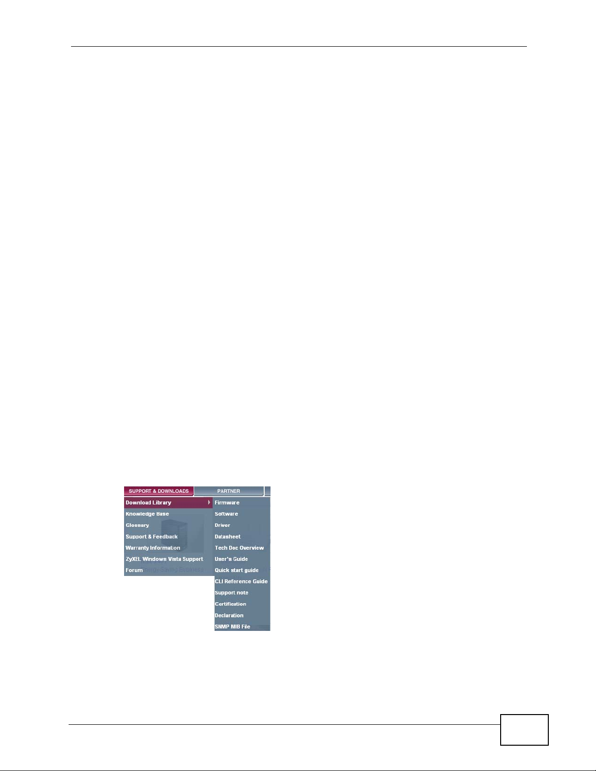
• Download Library
Search for the latest product updates and documentation from this link. Read
the Tech Doc Overview to find out how to efficiently use the documentation in
order to better understand how to use your product.
N4100 User’s Guide
3
Page 4

About This User's Guide
• Knowledge Base
If you have a specific question about your product, the answer may be here.
This is a collection of answers to previously asked questions about ZyXEL
products.
•Forum
This contains discussions on ZyXEL prod ucts. Learn from others who use ZyXEL
products and share your experiences as well.
Customer Support
Should problems arise that cannot be solved by the methods listed above, you
should conta ct your vendor. If you cannot contact your vend or, then contact a
ZyXEL office for the region in which you bought the device.
See http://www.zyxel.com/web/contact_us.php for contact information. Please
have the following informatio n ready when you contact an office.
• Product model and serial number.
•Warranty Information.
• Date that you received your device.
• Brief description of the problem and the steps you took to solve it.
4
N4100 User’s Guide
Page 5

Document Conventions
Document Conventions
Warnings and Notes
These are how warnings and notes are shown in this User’s Guide.
Warnings tell you about things that could harm you or your device.
Note: Notes tell you other important information (for example, other things you may
need to configure or helpful tips) or recommendations.
Syntax Conventions
• This product may be referred to as the “N4100”, the “device” or the “system” in
this User’s Guide.
• Product labels, screen names, field labels and field choices are all in bold font.
• A key stroke is denoted by square brackets and uppercase text, for example,
[ENTER] means the “enter” or “return” key on your keyboard.
• “Enter” means for you to type one or more characters and then press the
[ENTER] key. “Select” or “choose” means for you to use one of the predefined
choices.
• A right angle bracket ( > ) within a screen name denotes a mouse click. For
example, Maintenance > Log > Log Setting means you first click
Maintenance in the navigation panel, then the Log sub menu and finally the
Log Setting tab to get to that screen.
• Units of measurement may denote the “metric” value or the “scientific” value.
For example, “k” for kilo may denote “1000” or “1024”, “M” for mega may
denote “1000000” or “1048576” and so on.
• “e.g.,” is a shorthand for “for instance”, and “i.e.,” means “that is” or “in other
words”.
N4100 User’s Guide
5
Page 6
Document Conventions
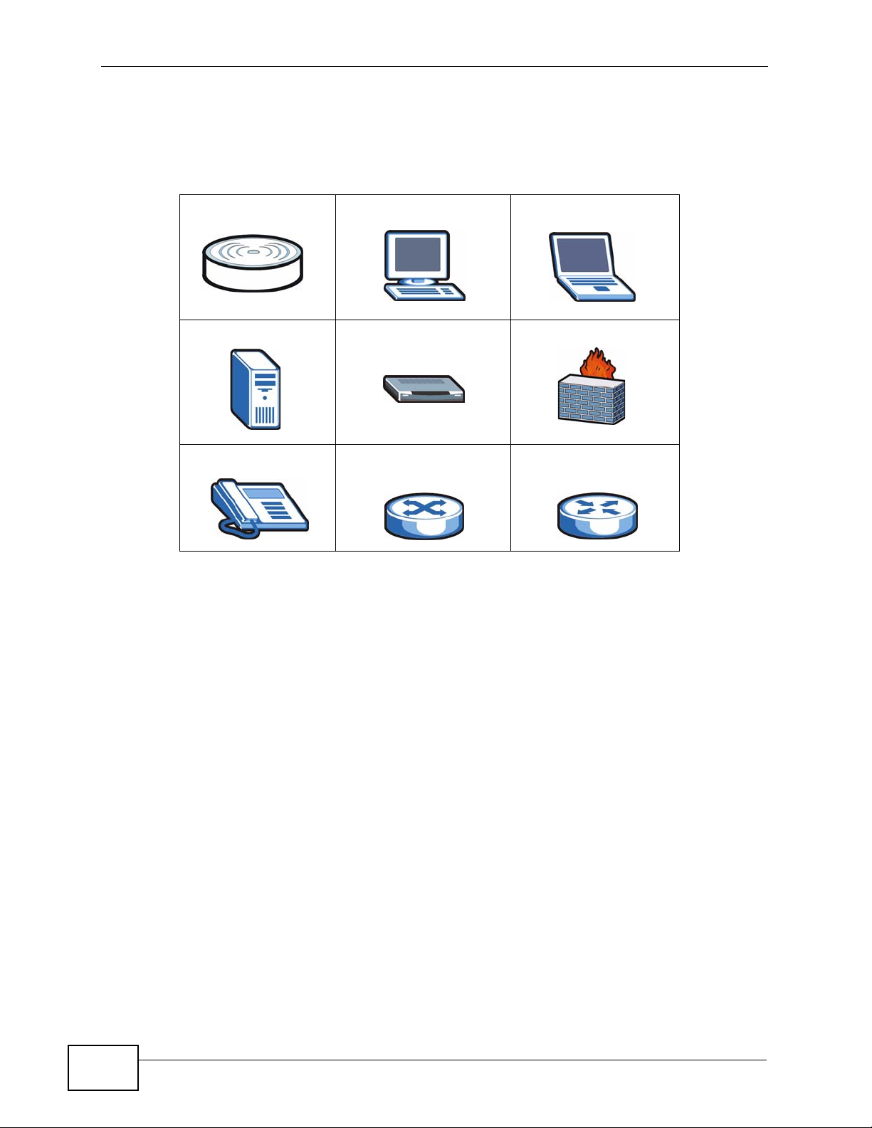
Icons Used in Figures
Figures in this User’s Guide may use the foll owing generic icons. The N4100 icon is
not an exact representation of your device.
N4100 Computer Notebook computer
Server Modem Firewall
Telephone Switch Router
6
N4100 User’s Guide
Page 7

Safety Warnings
Safety Warnings
• Do NOT use this product near water, for example, in a wet basement or near a swimming
pool.
• Do NOT expose your device to dampness, dust or corrosive liquids.
• Do NOT store things on the device.
• Do NOT install, use, or service this device during a thunderstorm. There is a remote risk
of electric shock from lightning.
• Connect ONLY suitable accessories to the device.
• Do NOT open the device or unit. Opening or removing covers can expose you to
dangerous high voltage points or other risks. ONLY qualified service personnel should
service or disassemble this device. Please contact your vendor for further information.
• Make sure to connect the cables to the correct ports.
• Place connecting cables carefully so that no one will step on them or stumble over them.
• Always disconnect all cables from this device before servicing or disassembling.
• Use ONLY an appropriate power adaptor or cord for your device.
• Connect the power adaptor or cord to the right supply voltage (for example, 110V AC in
North America or 230V AC in Europe).
• Do NOT allow anything to rest on the power adaptor or cord and do NOT place the
product where anyone can walk on the power adaptor or cord.
• Do NOT use the device if the power adaptor or cord is damaged as it might cause
electrocution.
• If the power adaptor or cord is damaged, remove it from the device and the power
source.
• Do NOT attempt to repair the power adaptor or cord. Contact your local vendor to order a
new one.
• Do not use the device outside, and make sure all the connections are indoors. There is a
remote risk of electric shock from lightning.
• Do NOT obstruct the device ventilation slots, as insufficient airflow may harm your
device.
• Antenna Warning! This device meets ETSI and FCC certification requirements when using
the included antenna(s). Only use the included antenna(s).
• If you wall mount your device, make sure that no electrical lines, gas or water pipes will
be damaged.
Your product is marked with this symbol, which is known as the WEEE
mark. WEEE stands for Waste Electronics and Electrical Equipment. It
means that used electrical and electronic products should not be mixed
with general waste. Used electrical and electronic equipment should be
treated separately.
N4100 User’s Guide
7
Page 8

Safety Warnings
8
N4100 User’s Guide
Page 9

Contents Overview
Contents Overview
User’s Guide ......................................... .......... ........... .......... ........... ........................................19
Introduction .................................. .................................................... .......................................... 21
The Web Configurator ............................................................................................................... 27
Tutorials .....................................................................................................................................35
Technical Reference ..............................................................................................................61
System Setup ........................... ... .... ... ... ... ................................................................. ... .............63
WAN/LAN ..................................................................................................................................71
Server ........................................................................................................................................81
Authentication ..................................... ....................................................... ................................ 89
RADIUS .....................................................................................................................................93
Billing ......................................................................................................................................... 99
Accounting ................................ .................................................... ........................................... 103
Credit Card .............................................................................................................................. 109
Keypad .....................................................................................................................................113
Customization ..................................... ....................................................... ...............................119
Pass Through ..........................................................................................................................143
Filtering ..................................... .................................................... ........................................... 147
Share .......................................................................................................................................151
Portal Page, Advertisement Links and Walled Garden .............................. ......................... ..... 153
DDNS ...................................................................................................................................... 159
LAN Devices ............................................................................................................................163
Syslog ....................................... .................................................... ........................................... 167
Session Trace ........... ... ... .... ... ................................................................ .... ... ... ........................175
Secure Remote ........................................................................................................................ 181
SNMP ......................................................................................................................................183
Bandwidth ........................................ ............................................................. ...........................187
Wireless LAN ............................................... ................................................................. ...........189
Account Generator ..................................................................................................................203
Licensing .................................................................................................................................207
System Status ..................................... ... ... ... .... .........................................................................211
Configuration and Firmware ....................................................................................................225
System Account .............. .... ................................................................ ... .... ... ... ... .... ... ..............239
SSL Certificate ......................................................................................................................... 243
Ping Command ........................................................................................................................245
Restart .....................................................................................................................................247
Troubleshooting ..................................................... .................................................................. 249
Product Specifications ............................................................................................................. 255
N4100 User’s Guide
9
Page 10

Contents Overview
10
N4100 User’s Guide
Page 11

Table of Contents
Table of Contents
About This User's Guide..........................................................................................................3
Document Conventions............................................................................................................5
Safety Warnings ........................................................................................................................7
Contents Overview ...................................................................................................................9
Table of Contents....................................................................................................................11
Part I: User’s Guide................................................................................ 19
Chapter 1
Introduction.............................................................................................................................21
1.1 Overview ............. ................................................................. ... ... .......................................... 21
1.2 Managing the N4100 ...........................................................................................................21
1.3 Good Habits for Managing the N4100 .................................................................................22
1.4 Applications for the N4100 ........................................... ... .... ... ... ... ....................................... 22
1.4.1 Internet Access .........................................................................................................22
1.4.2 Wireless Connection ................................. .... ... ... ... .... ... ... ... ... .................................... 23
1.5 Restoring Factory Defaults .......... ... ... ... .... ................................................................ ... .... ... 24
1.5.1 Using the Reset Button .............................................................................................. 24
1.6 LEDs (Lights) .......................................................................................................... .............25
Chapter 2
The Web Configurator............................................................................................................27
2.1 Overview ............... ................................................................. ... ... ....................................... 27
2.1.1 Accessing the Web Configurator ................................................................................27
2.2 Web Configurator Main Screen ...........................................................................................29
2.2.1 Navigation Panel .............................. ..........................................................................29
2.2.2 Main Window .......................... ... ................................................................. ... ... ... .......32
2.2.3 Status Bar ............................................... ... ................................................................. 32
2.2.4 Wizard Setup Screens ........ ... ... ... .... ... .......................................................................32
2.2.5 System Quick View Screen ........................................................................................ 33
Chapter 3
Tutorials...................................................................................................................................35
3.1 Overview ............. ................................................................. ... ... .......................................... 35
N4100 User’s Guide
11
Page 12

Table of Contents
3.2 Wireless Network Setup ..................... ... .... ... ... ... .... ... .......................................................... 35
3.2.1 Configuring the N4100 Wireless Network Settings .................................................... 36
3.2.2 Connecting to the N4100 Wirelessly ................ ... ... .... ... ... ... ... .... ................................ 37
3.3 Subscriber Authentication and Account Generation ............................................................ 38
3.3.1 Creating Accounts in the Web Configurator ........................... .................................... 39
3.3.2 Using a Statement Printer to Create Accounts and Print Subscriber Statements ..... 41
3.3.3 Viewing the Account List ............................................................................................41
3.4 Subscriber Login ................. ... .... ... ... ... ... .... .......................................................................... 42
3.5 Report Printing Using the SP300E ......................................................................................42
3.5.1 Reports Overview ..................... ................................................................. ... ... ..........4 3
3.5.2 Key Combinations ....................... ................................................................. ... ... .......43
3.5.3 Daily Account Summary ............................................................................................ 43
3.5.4 Monthly Account Summary ....................................................................................... 44
3.5.5 Account Report Notes ................................................................................................45
3.5.6 System Status ....................... ... ... .... ... ... ... .................................................................45
3.5.7 Network Statistics ................ ... ... ... .... ... ................................................................ .... ...47
3.6 Using DDNS to access the N4100 ...................................................................................... 49
3.6.1 Registering a DDNS Account on www.dyndns.org .................................................... 49
3.6.2 Configuring DDNS on Your N4100 ............................................................................. 50
3.6.3 Testing the DDNS Setting ................... ... ... .... ... ... ... .... ... ............................................. 50
3.7 Accessing the Devices on the LAN from the WAN .............................................................. 51
3.8 Using SSL Security for Connections between the N4100 and your Computer ................... 52
3.8.1 Activating SSL Security for Management Connections ....... ............. ................ .......... 52
3.8.2 Viewing and Installing the SSL Security Certificate .................................. ... ... ... .... ... 53
3.8.3 Activating SSL Security for Subscriber Logins ........... ......................................... ....... 58
3.8.4 Using a New Certificate for SSL Security ................................................................... 58
Part II: Technical Reference. ................................................................. 61
Chapter 4
System Setup..........................................................................................................................63
4.1 Overview ............. ................................................................. ... ... .......................................... 63
4.1.1 What Yo u Can Do in this Chapter .............................................................................. 63
4.1.2 What You Need to Know ............................................................................... ... ... .... ... 63
4.2 The System Screen .................... ... ................................................................. ... ... ... ... ....... 64
4.3 Technical R eference ........................... ... .... ... ... ... .... ... ... ... .... ................................................ 67
4.3.1 iPnP ZyXEL Implementation ...................................................................................... 68
4.3.2 How iPnP Works ........................................................................................................69
Chapter 5
WAN/LAN.................................................................................................................................71
12
N4100 User’s Guide
Page 13

Table of Contents
5.1 Overview ............. ................................................................. ... ... .......................................... 71
5.1.1 What Yo u Can Do in this Chapter .............................................................................. 71
5.1.2 What You Need to Know ............................................................................... ... ... .... ... 71
5.2 The WAN/LAN Screen .......................................................................................................73
5.3 Technical R eference ........................... ... .... ... ... ... .... ... ... ... .... ................................................ 76
Chapter 6
Server.......................................................................................................................................81
6.1 Overview ............. ................................................................. ... ... .......................................... 81
6.1.1 What Yo u Can Do in this Chapter .............................................................................. 81
6.1.2 What You Need to Know ............................................................................... ... ... .... ... 81
6.2 The Server Screen ............................................................................................................84
6.3 The Static DHCP Table Screen ...........................................................................................86
Chapter 7
Authentication.........................................................................................................................89
7.1 Overview ............. ................................................................. ... ... .......................................... 89
7.1.1 What Yo u Can Do in this Chapter .............................................................................. 89
7.2 The Authentication Screen ................................................................................................89
Chapter 8
RADIUS....................................................................................................................................93
8.1 Overview ............. ................................................................. ... ... .......................................... 93
8.1.1 What Yo u Can Do in this Chapter .............................................................................. 93
8.2 The RADIUS Screen .. ... ................................................................ .... ... ... ... .... ... ... .............93
Chapter 9
Billing.......................................................................................................................................99
9.1 Overview ............. ................................................................. ... ... .......................................... 99
9.1.1 What Yo u Can Do in this Chapter .............................................................................. 99
9.1.2 What You Need to Know ............................................................................... ... ... .... ... 99
9.2 The Billing Screen ...... ... ... ... .... ................................................................ ... .... ... ... ... ........100
Chapter 10
Accounting............................................................................................................................103
10.1 Overview .......................................................................................................................... 103
10.1.1 What Yo u Can Do in this Chapter .......................................................................... 103
10.1.2 What You Need to Know ........................................................................................ 103
10.2 The Accounting Screen .................................................................................................104
10.2.1 Charge By Levels Example .................................................................................... 106
Chapter 11
Credit Card ............................................................................................................................109
N4100 User’s Guide
13
Page 14

Table of Contents
11.1 Overview ..........................................................................................................................109
11.1.1 What You Can Do in this Chapter ................................ ... ... ... .................................. 109
11.2 The Credit Card Screen ..................................................................................................110
Chapter 12
Keypad...................................................................................................................................113
12.1 Overview ...........................................................................................................................113
12.1.1 What Yo u Can Do in this Chapter ...........................................................................113
12.2 The Keypad Screen ........................................................................................................114
12.3 Keypad Configuration Examples ......................................................................................115
12.3.1 Keypad with Pre-Paid Billing Example ....................................................................115
12.3.2 Keypad with Post-Paid Billing Example ......................................... ... .... ... ... ... ... .... ..117
Chapter 13
Customization.......................................................................................................................119
13.1 Overview ...........................................................................................................................119
13.1.1 What Yo u Can Do in this Chapter ...........................................................................119
13.1.2 What You Need to Know .........................................................................................119
13.2 The Login Page Screen ............................................................ ... .... ... ...........................120
13.2.1 Standard .................................................................................................................122
13.2.2 Redirect .................................................................................................................. 123
13.2.3 Advanced ...............................................................................................................125
13.2.4 Frame ..................................................................................................................... 126
13.3 The Logo Screen ........................................................................................................... 127
13.4 The Information Windows Screen ................................................................................. 128
13.5 The Account Printout Screen .........................................................................................129
13.6 The Credit Card Screen ............................ ... ... .... ... ... ... .... ... ... ... ... .... ..............................134
13.6.1 Credit Card Standard Login Page .......................................................................... 135
13.6.2 Credit Card Service Selection Page ....................................................................... 136
13.6.3 Credit Card Successful Page .................................................................................139
13.6.4 Credit Card Fail Page ..................... ... ... ... .... ... ... ... .................................................. 140
Chapter 14
Pass Through........................................................................................................................143
14.1 Overview .......................................................................................................................... 143
14.1.1 What Yo u Can Do in this Chapter .......................................................................... 143
14.2 The Pass Through Screen .............................................................................................143
Chapter 15
Filtering..................................................................................................................................147
15.1 Overview .......................................................................................................................... 147
15.1.1 What Yo u Can Do in this Chapter .......................................................................... 147
15.2 The Filtering Screen ......................................................................................................147
14
N4100 User’s Guide
Page 15

Table of Contents
Chapter 16
Share......................................................................................................................................151
16.1 Overview .......................................................................................................................... 151
16.1.1 What Yo u Can Do in this Chapter .......................................................................... 151
16.2 The Share Screen .........................................................................................................151
Chapter 17
Portal Page, Advertisement Links and Walled Garden .....................................................153
17.1 Overview .......................................................................................................................... 153
17.1.1 What Yo u Can Do in this Chapter .......................................................................... 153
17.1.2 What You Need to Know ........................................................................................ 153
17.2 The Portal Page Screen ................................................................................................154
17.3 The Advertisement Screen ............................................................................................155
17.4 The Walled Garden Screen ............................ .... ... ... ... .... ... ... ... ... .................................. 156
17.4.1 Walled Garden Login Example ............................................................................... 156
Chapter 18
DDNS......................................................................................................................................159
18.1 Overview .......................................................................................................................... 159
18.1.1 What Yo u Can Do in this Chapter .......................................................................... 159
18.1.2 What You Need to Know ........................................................................................ 159
18.2 The DDNS Screen .........................................................................................................160
Chapter 19
LAN Devices..........................................................................................................................163
19.1 Overview .......................................................................................................................... 163
19.1.1 What Yo u Can Do in this Chapter .......................................................................... 163
19.1.2 What You Need to Know ........................................................................................ 163
19.2 The LAN Devices Screen .............................................................................................. 164
19.2.1 LAN Device Management Example ....................................................................... 165
Chapter 20
Syslog....................................................................................................................................167
20.1 Overview .......................................................................................................................... 167
20.1.1 What Yo u Can Do in this Chapter .......................................................................... 167
20.2 The Syslog Screen ........................................................................................................168
20.3 The Log Settings Screen ............................................................................................... 170
Chapter 21
Session Trace........................................................................................................................175
21.1 Overview .......................................................................................................................... 175
21.1.1 What Yo u Can Do in this Chapter .......................................................................... 175
21.2 The Session Trace Screen ............................................................................................ 176
N4100 User’s Guide
15
Page 16

Table of Contents
21.3 Session Trace Filename Convention ...............................................................................178
Chapter 22
Secure Remote......................................................................................................................181
22.1 Overview .......................................................................................................................... 181
22.1.1 What Yo u Can Do in this Chapter .......................................................................... 181
22.2 The Secure Remote Screen ..........................................................................................181
Chapter 23
SNMP......................................................................................................................................183
23.1 Overview .......................................................................................................................... 183
23.1.1 SNMP Traps ...........................................................................................................184
23.1.2 What Yo u Can Do in this Chapter .......................................................................... 184
23.2 The SNMP Screen .........................................................................................................184
Chapter 24
Bandwidth..............................................................................................................................187
24.1 Overview .......................................................................................................................... 187
24.1.1 What Yo u Can Do in this Chapter .......................................................................... 187
24.2 The Bandwidth Screen ..................................................................................................188
Chapter 25
Wireless LAN.........................................................................................................................189
25.1 Overview .......................................................................................................................... 189
25.1.1 What Yo u Can Do in this Chapter .......................................................................... 189
25.2 What You Need to Know ..................................................................................................189
25.3 Before You Begin ............................................................................................................. 191
25.4 The Wireless Screen .....................................................................................................192
25.5 Technical Reference ........................................................................................................ 198
25.5.1 Wireless Network Overview ................................................................................... 198
25.5.2 Additional Wireless Terms ........................................................... ........................... 199
25.5.3 Wireless Security Overview ................................................................................... 199
Chapter 26
Account Generator ...............................................................................................................203
26.1 Overview .......................................................................................................................... 203
26.1.1 What Yo u Can Do in this Chapter .......................................................................... 203
26.2 The Account Generator Screen ..................................................................................... 204
Chapter 27
Licensing...............................................................................................................................207
27.1 Overview .......................................................................................................................... 207
27.1.1 What Yo u Can Do in this Chapter .......................................................................... 207
16
N4100 User’s Guide
Page 17

Table of Contents
27.2 The Registration Screen ..................................... ................................................... ........207
27.3 The Service Screen .......................................................................................................209
Chapter 28
System Status.......................................................................................................................211
28.1 Overview ...........................................................................................................................211
28.1.1 What Yo u Can Do in this Chapter ...........................................................................211
28.2 The System Screen .........................................................................................................212
28.3 The Account List Screen ... .... ... ... ... ................................................................. ..............216
28.4 The Account Log Screen ...............................................................................................218
28.5 The Current User Screen ..............................................................................................220
28.6 The DHCP Client Screen ............................................................................................... 221
28.7 The Session List Screen ................................................................................................222
28.8 The LAN Devices Screen .............................................................................................. 223
28.8.1 Accessing a LAN Device ..................................... .......................................... ........ 224
Chapter 29
Configuration and Firmware................................................................................................225
29.1 Overview .......................................................................................................................... 225
29.1.1 Some Warnings ......................................................................................................225
29.1.2 What Yo u Can Do in this Chapter .......................................................................... 225
29.1.3 What You Need To Know ....................................................................................... 225
29.2 The Configuration Screen ...............................................................................................226
29.2.1 Backup Configuration Using HTTP ....................................................................... 226
29.2.2 Backup Configuration Using TFTP ......................................................................... 228
29.2.3 Restore Configuration Using HTTP ................... ... .... ... ... ... ... .... ... ... ... .... ... ... ... ... .... . 229
29.2.4 Restore Configuration Using TFTP ................... ... .... ... ... ... ... .... ... ... ... .... ... ... ... ... .... . 230
29.2.5 Restore Factory Defaults ....................................................................................... 232
29.3 The Firmware Screen ....................................................................................................232
29.3.1 Manual Firmware Upgrade Using the Web Configurator .......................................233
29.3.2 Manual Firmware Upgrade via TFTP Server ......................................................... 234
29.3.3 Manual Boot Code Upgrade Using the Web Configurator .....................................235
29.3.4 Scheduled Firmware Upgrade ...............................................................................236
Chapter 30
System Account....................................................................................................................239
30.1 Overview .......................................................................................................................... 239
30.1.1 What Yo u Can Do in this Chapter .......................................................................... 239
30.2 The System Account Screen ........................................................................................... 240
Chapter 31
SSL Certificate ......................................................................................................................243
31.1 Overview .......................................................................................................................... 243
N4100 User’s Guide
17
Page 18

Table of Contents
31.1.1 What Yo u Can Do in this Chapter .......................................................................... 243
31.2 The SSL Certificate Screen ........................ ... ... .... ... ... ... .... ... ... ... ... .... ... ... ... .... ... ... ... ... .... . 243
Chapter 32
Ping Command......................................................................................................................245
32.1 Overview .......................................................................................................................... 245
32.1.1 What Yo u Can Do in this Chapter .......................................................................... 245
32.2 The Ping Command Screen ............................................................................................245
Chapter 33
Restart....................................................................................................................................247
33.1 Overview .......................................................................................................................... 247
33.1.1 What Yo u Can Do in this Chapter .......................................................................... 247
33.2 The Restart Screen .... .....................................................................................................247
Chapter 34
Troubleshooting....................................................................................................................249
34.1 Overview .......................................................................................................................... 249
34.2 Power, Hardware Connections, and LEDs ........... ... ... ... .... ... ........................................... 249
34.3 N4100 Access and Login ................................................................................................. 250
34.4 Internet Access ................................................................................................................251
34.5 Wireless LAN Troubleshooting ........................................................................................252
Chapter 35
Product Specifications.........................................................................................................255
Appendix A Setting Up Your Computer’s IP Address...........................................................261
Appendix B Pop-up Windows, JavaScripts and Java Permissions......................................291
Appendix C IP Addresses and Subnetting ...........................................................................301
Appendix D Wireless LANs ..................................................................................................313
Appendix E Common Services.............................................................................................329
Appendix F Open Software Announcements .......................................................................333
Appendix G Legal Information..............................................................................................339
Index.......................................................................................................................................343
18
N4100 User’s Guide
Page 19

PART I
User’s Guide
19
Page 20

20
Page 21
CHAPTER 1
Introduction
1.1 Overview
The N4100 combines an IEEE 802.11n wireless access point, router, 4-port switch
and service gateway in one box. If you have a "statement printer", you can
connect it directly to the N4100, allowing you to easily print subscriber
statements. The N4100 is ideal for offices, coffee shops, libraries, hotels and
airport terminals catering to subscribers that seek Internet access. You should
have an Internet account already set up and have been given usernames,
passwords etc. required for Internet access.
1.2 Managing the N4100
Use the N4100’s built-in Web Configurator to manage it. You can connect to it
using a web browser such as Firefox 2.0 (and higher) or Internet Explorer 6 (and
higher). The web configurator gives you access to all the a vailable setti ngs for this
product. For details on connecting to it, see the Quick Start Guide.
N4100 User’s Guide
21
Page 22

Chapter 1 Introduction
1.3 Good Habits for Managing the N4100
Do the following things regularly to make the N4100 more secure and to manage
the N4100 more effectively.
• Change the password. Use a password that’s not easy to guess and that consists
of different types of characters, such as numbers and letters.
• Write down the password and put it in a safe place.
• Back up the configuration (and make sure you know how to restore it).
Restoring an earlier working configuration may be useful if the device becomes
unstable or even crashes. If you forget y our password, you will hav e to reset the
N4100 to its factory default settings. If you backed up an earlier configuration
file, you would not have to totally re-configure the N4100. You could simply
restore your last configuration.
1.4 Applications for the N4100
Here are some example uses for which the N4100 is well suited.
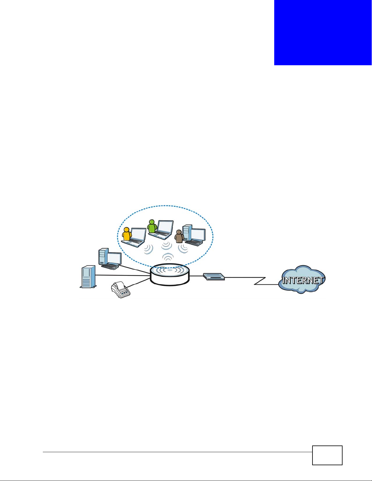
1.4.1 Internet Access
With a broadband modem or router (A), the N4100 allows the attached computers
to enjoy high speed Internet access. Computers can connect to the ZyXEL
Device's LAN ports (or wirelessly).
In public areas, such as a hotel or coffee shop, the N4100 provides high speed
Internet access to subscribers with account billing and authentication, which can
be done using a statement printer (B) and local subscriber database.
You can also configure filtering on the N4100 for secure Internet access. Use
filtering to block access to specific IP addresses or web sites. For example, you
could block subscriber access to pornographic or gambling web sites (2).
22
N4100 User’s Guide
Page 23

Figure 1 Internet Access Applicarion
Chapter 1 Introduction
1.4.2 Wireless Connection
By default, the wireless LAN (WLAN) is enabled on the N4100. IEEE 802.11b/g/n
compliant clients can wirelessly connect to the N4100 to access network
resources. The N4100 functions as an access point (AP) to bridge the wired and
the wireless network allowing wireless stations to access the Internet through the
N4100.
Figure 2 Wireless Connection Application
WLAN
B
A
1
2
LAN
N4100 User’s Guide
WAN
23
Page 24

Chapter 1 Introduction
1.5 Restoring Factory Defaults
You can erase the current configuration and restore factory defaults using either
the web configurator or the RESET button at the back of the device.
The web configurat or allows you to re set the system but retain subscriber account
information. See Chapter 29 on page 225 for more information.
If you forget your password or cannot access the web configurator, you will need
to use the RESET button to reload the factory-default configuration file. This
means that you will lose all of your custom configuration, including the local
subscriber database, and the administrator password will be reset to “1234”.
1.5.1 Using the Reset Button
1 Make sure the POWER LED is on (not blinking).
2 T o set the device back to the factory defa ult settings, use a pointed object to press
the RESET button once or until the PWR LED begins to blink and then release it.
When the PWR LED begins to blink, the defaults have been restored and the
device restarts.
24
N4100 User’s Guide
Page 25

1.6 LEDs (Lights)
The following graphic displays the labels of the LEDs.
Figure 3 LEDs on the Front Panel
Chapter 1 Introduction
None of the LEDs are on if the N4100 is not receiving power.
Table 1 LED Descriptions
LED COLOR STATUS DESCRIPTION
PWR Green On The N4100 is receiving power.
Off The N4100 is not receiving power.
SYS Green On The N4100 is ready and running.
Off The N4100 is not ready or has failed.
WLAN Green On The wireless network is activated.
Blinking The N4100 is communicating with other wireless
clients.
Off The wireless network is not activated.
WAN Green On The N4100 has an Ethernet connection with another
device (such as a broadband modem) through this
port.
Blinking The N4100 is sending/receiving data through this
port.
Off The N4100 does not have an Ethernet connection
through this port.
N4100 User’s Guide
25
Page 26

Chapter 1 Introduction
Table 1 LED Descriptions
LED COLOR STATUS DESCRIPTION
LAN 1~4 Green On The N4100 has an Ethernet connection with another
Refer to the Quick Start Guide for information on hardware connections.
device (such as a computer) through this port.
Blinking The N4100 is sending/receiving data through this
port.
Off The N4100 does not have an Ethernet connection
through this port.
26
N4100 User’s Guide
Page 27

CHAPTER 2
The Web Configurator
2.1 Overview
The web configurator is an HTML-based managem ent interface that allows easy
device setup and management via Internet browser. Use Internet Explorer 6.0 and
later or Firefox 2.0 and later versions. The recommended screen resolution is
1024 by 768 pixels.
In order to use the web configurator you need to allow:
• Web browser pop -up windows from your device. W eb pop-up blocking is enabl ed
by default in Windows XP SP (Service Pack) 2.
• JavaScript (enabled by default).
• Java permissions (enabled by default).
See Appendix B on page 291 if you need to make sure these functions are allowed
in Internet Explorer.
2.1.1 Accessing the Web Configurator
Note: The N4100 allows only one web configurator session at a time.
1 Make sure you r N4100 hardware is p roperly connected (refer to the Quick Start
Guide for details on this).
2 Launch your web browser.
N4100 User’s Guide
27
Page 28
Chapter 2 The Web Configurator
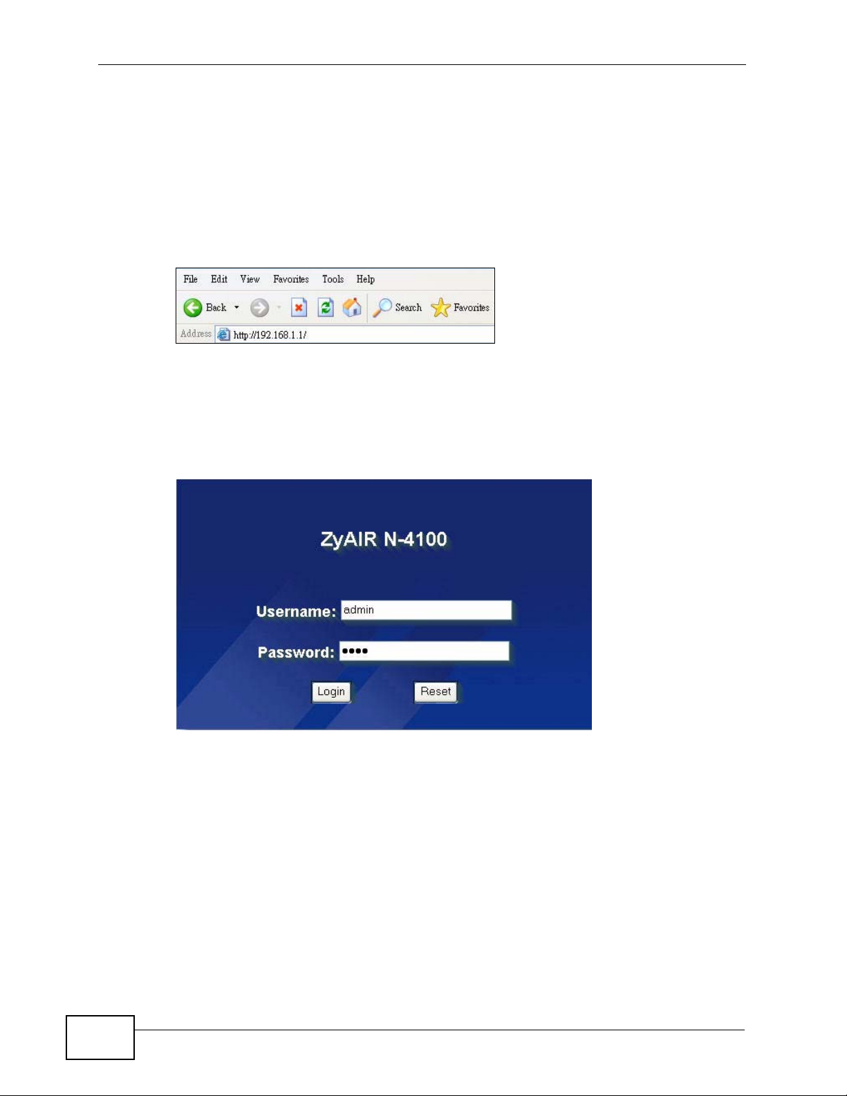
3 Launch your web browser and type the WAN or LAN IP address of the N4100 as
the web address (it is recommended that you connect your computer to the LAN
and use the LAN IP address for initial configuration). 192.168.1.1 is the default
IP address for the LAN port.
If you are using a different port number (between 8000 and 8099) for the web
server, you must also append the port number to the LAN IP address separated
with a colon ":", for example, http://192.168.1.1:8080.
Figure 4 N4100’s IP Address
4 A password screen displays. Enter your user name and password. The default
administrator user name is admin and the default password is 1234. Click Login.
Note: The user name and password are case sensitive.
Figure 5 Password Screen
5 You should see the first screen of the Wi zard setup. R efer to the Quick Start Guide
for more information on configuring the Wizard setup screens.
Note: For security reasons, the N4100 automatically logs you out if there is no activity
for longer than five minutes after you log in. If this happens, simply log back in
again. You can change the time period in the ADVANCED > SERVER screen's
Administrator Idle-Timeout field.
28
N4100 User’s Guide
Page 29

Chapter 2 The Web Configurator
2.2 Web Configurator Main Screen
The main screen is divided into these parts:
Figure 6 Main Screen
A
C
• A - navigation panel
• B - main window
• C - status bar
2.2.1 Navigation Panel
B
Use the menu items on the navigation panel to open screens to configure N4100
features. The following tables describe each menu item.
Table 2 Navigation Panel Summary
LINK TAB FUNCTION
WIZARD Use these screens for initial configuration including WAN and
wireless setup, subscriber authentication, billing profile, account
generating, statement printout, and system password and time.
ADVANCED
SYSTEM Use this screen to configure your device’s name, change your
N4100’s time and date, configure from which IP address(es) users
can manage the N4100, enable NAT and other system-related
general settings.
WAN/LAN Use this screen to set the LAN IP address, and configure the WAN
settings on the N4100 for Internet access.
N4100 User’s Guide
29
Page 30

Chapter 2 The Web Configurator
Table 2 Navigation Panel Summary
LINK TAB FUNCTION
SERVER Server Use this screen to set the embedded web server, the LAN DHCP
server and specify the e-mail server for e-mail redirection.
Static DHCP
Table
AUTHENTICA
TION
RADIUS Use this screen to configure the N4100 to use an external RADIUS
BILLING Use this screen to set up subscriber billing.
ACCOUNTING Use this screen to set up and manage subscriber accounts.
CREDIT
CARD
KEYPAD Use this screen to set up the optional keypad for a statement
CUSTOMIZAT
ION
PASS
THROUGH
FILTERING Use this screen to block subscriber access to a list of destinations.
SHARE Use this screen to allow logged-in subscribers to share devices on
PORTAL PAGE Use this screen to set the first web site to which a subscriber is
ADVERTISEM
ENT
WALLED
GARDEN
DDNS This screen allows you to use a static hostname alias for a
LAN DEVICES Use this screen to configure port mapping to make LAN devices
SYSLOG Syslog Use this screen to configure the syslog server information. You
SESSION
TRACE
Login Page Use this screen to customize the subscriber login screen.
Logo Use this screen to upload your logo file.
Information
Windows
Account
Printout
Credit Card Use this screen to customize the subscriber credit card billing
Log Settings Use this screen to select which logs your N4100 is to send and the
Use this screen to assign IP addresses on the LAN to specific
individual computers based on their MAC Addresses.
Use this screen to set up subscriber authentication on the N4100.
server.
Use this screen to set the N4100 to handle credit card
transactions.
printer.
Use this screen to customize the information window on the
subscriber's computer after a successful login.
Use this screen to customize the account printout.
interface.
Use this screen to specify devices that can have traffic pass
through the N4100.
the LAN.
redirected after logging in successfully.
Use this screen to set advertisement links.
Use this screen to create walled garden web sites.
dynamic IP address.
behind the N4100 visible to the outside world.
can also set it to e-mail the logs to you.
schedule for when the N4100 is to send the logs.
Use this screen to configure the N4100 to record details about
subscriber Internet access and to where the N4100 sends logs of
the session traces.
30
N4100 User’s Guide
Page 31

Chapter 2 The Web Configurator
Table 2 Navigation Panel Summary
LINK TAB FUNCTION
SECURE
REMOTE
SNMP Use this screen to to configure your N4100's settings for Simple
BANDWIDTH Use this screen to limit the amount of upstream and downstream
WIRELESS Use this screen to configure the wireless LAN settings, WLAN
ACCOUNT
GENERATOR
LICENSING Registration Use this screen to register your N4100 with myZyXEL.com.
Service Use this screen to upgrade a service and update your service
SYSTEM ST ATUS
SYSTEM This screen shows the current state of the N4100.
ACCOUNT
LIST
ACCOUNT
LOG
CURRENT
USER
DHCP CLIENT This screen shows current DHCP client information of all network
SESSION LIST This screen shows incoming and outgoing packet information.
LAN DEVICES This screen shows the status of LAN devices configured in the
SYSTEM TOOLS
CONFIGURAT
ION
FIRMWARE Manual
Firmware
Upgrade
Scheduled
Firmware
Upgrade
SYSTEM
ACCOUNT
SSL
CERTIFICATE
PING
COMMAND
RESTART This screen allows you to reboot the N4100 without turning the
LOGOUT Click this link to log out of the web configurator.
QUICK VIEW Use this screen to view key system status information.
Use this screen to allow the N4100 to send RADIUS packets,
syslogs and log e-mails through a PPTP VPN tunnel.
Network Management Protocol (SNMP) management.
bandwidth each user can use.
authentication/security settings.
Use this screen to use the N4100 with one or more account
generators (statement printers).
subscription status.
This screen shows the subscriber account list.
This screen shows information on the N4100's subscriber account
logs.
This screen shows a list of subscribers currently logged on to the
N4100 for Internet access.
clients using the DHCP server on the N4100.
ADVANCED > LAN DEVICES screen.
Use this screen to backup and restore your device’s configuration
(settings) or reset the factory default settings.
Use this screen to manually upload firmware to your device.
Use this screen to automatically download the latest firmware
from a TFTP server.
Use this screen to configure your N4100’s login user names and
passwords.
Use this screen to download a CA registered certificate from a
computer connected to the N4100.
Use this screen to test the Internet connection.
power off.
N4100 User’s Guide
31
Page 32

Chapter 2 The Web Configurator
2.2.2 Main Window
The main window displays information and configuration fields. It is discussed in
the rest of this document.
2.2.3 Status Bar
Check the status bar when you click Apply or OK to verify that the configuration
has been updated.
2.2.4 Wizard Setup Screens
The Wizard setup screens display when you first access the N4100. Refer to the
Quick Start Guide for information on how to configure the Wizard setup screens.
32
N4100 User’s Guide
Page 33

2.2.5 System Quick View Screen
click QUICK VIEW to display the following screen. This screen displays key
system status information.
Figure 7 Quick View
Chapter 2 The Web Configurator
The following table describes the labels in this screen.
Table 3 Quick View
LABEL DESCRIPTION
System
Refresh Click Refresh to update this screen.
N4100 User’s Guide
33
Page 34

Chapter 2 The Web Configurator
Table 3 Quick View
LABEL DESCRIPTION
System/Host Name This field displays the description name of the N4100 for
Firmware Version This field displays the version of the firmware on the N4100.
Location Name This field displays the device’s geographical location.
Domain Name This field displays the domain name of the N4100.
System Time This field displays the N4100’s current time.
System Up Time This field displays the how long the N4100 has been operating
WAN MAC Address This field displays the MAC address of the N4100 on the WAN.
LAN MAC Address This field displays the MAC address of the N4100 on the LAN.
WLAN MAC Address This field displays the MAC address of the N4100 on the wireless
Network
WAN Status This field displays the status of the N4100’s connection to the
WAN Type This field displays the DHCP mode of the WAN port and whether
WAN IP Address
WAN Subnet Mask
LAN IP Address
LAN Subnet Mask
Default Gateway This field displays the IP address of the default gateway of the
DNS This field displays the IP address of the DNS server that the
Wireless
Wireless Service This field displays the status of the N4100’s wireless LAN.
ESSID This field displays the N4100’s Extended Service Set IDentity.
Wireless Channel This field displays the channel that the N4100 is using.
Encryption This field displays the type of data encryption that the N4100 is
identification purposes.
since it was last started.
LAN.
Internet (Established or Not Established).
the WAN port is connected to an Ethernet device. It displays
DHCP Client, Static IP Setting, PPPoE, or PPTP.
This field displays the IP address and the subnet mask of the WAN
port on the N4100.
This field displays the IP address and the subnet mask of the LAN
port on the N4100.
WAN port on the N4100.
N4100 is using.
using.
34
WEP, WPA or WPA2 displays if N4100 is using WEP, WPA or
WPA2 data encryption correspondingly. Disable displays if the
N4100 is not using data encryption.
Traffic
WAN This field displays traffic statistics for the N4100’s WAN
connection.
LAN This field displays traffic statistics for the N4100’ s LAN connection.
Wireless This field displays traffic statistics for the N4100’s wireless LAN
connection.
N4100 User’s Guide
Page 35

CHAPTER 3
Tutorials
3.1 Overview
This chapter describes:
• how to set up a wireless network (Section 3.2 on page 35).
• how to generate a subscriber account (Section 3.3 on page 38).
• how to log in as a subscriber (Section 3.4 on page 42).
• how to print reports using SP300E (Section 3.5 on page 42).
• how to access the N4100 using DDNS (Section 3.6 on page 49).
• how to remotely access or manage the device behind the N4100 (Section 3.7 on
page 51)
• how to set up and enable SSL security on the N4100 (Section 3.8 on page 52)
Note: The tutorials featured in this chapter require a basic understanding of
connecting to and using the Web Configurator on your N4100. For details, see
the included Quick Start Guide. For field descriptions of individual screens, see
the related technical reference in this User's Guide.
3.2 Wireless Network Setup
The N4100 is connected to a broadband modem with Internet access. Thomas
wants to set up a wireless network so that the users can use their notebooks or
computers to wirelessly access the Internet through the N4100. In this wireless
network, the N4100 serves as an access point (AP), and the notebook with a
wireless network card or USB/PCI adapter is the wireless client. The wireless client
can access the Internet through the AP.
N4100 User’s Guide
35
Page 36

Chapter 3 Tutorials
Thomas has to configure the wireless network settings on the N4100. Then users
can set up a wireless network using manual configuration (Section 3.2.2 on page
37).
3.2.1 Configuring the N4100 Wireless Network Settings
This example uses the following parameters to set up a wireless network.
SSID SSID_Example
Security Mode WPA-PSK
Pre-Shared Key DoNotStealMyWirelessNetwork
802.11 Mode IEEE 802.11b/g/n (Mixed)
Follow the steps below to configure the wireless settings on the N4100.
Note: To see the current SSID, go to the SYSTEM STATUS > SYSTEM or the
System Quick View screen.
1 Open the ADVANCED > WIRELESS screen in the N4100’s web configurator.
Configure the screen using the provided parameters (see page 36).
36
2 Make sure Enable is selected in the Wireless Connection field.
3 Enter “SSID_Example” as the ESSID and select a channel which is not used by
another AP.
N4100 User’s Guide
Page 37

Chapter 3 Tutorials
4 Select 802.11n + 802.11g + 802.11b in the 802.11 Mode field.
5 Set security mode to WPA, select the Use WPA/WPA2 with Pre-shared Key
option and enter “DoNotStealMyWirelessNetwork” in the Pre-shared Key field.
Click Apply.
6 Click QUICK VIEW to open the System Quick View screen. Verify your wireless
and wireless security settings and check if the WLAN connection is up.
7 The user can now use the notebook’s wireless client to search for the N4100 (see
Section 3.2.2 on page 37).
3.2.2 Connecting to the N4100 Wirelessly
Use the wireless adapter’s utility installed on the notebook to search for the
“SSID_Example” SSID. Then enter the “DoNotStealMyWirelessNetwork” preshared key to establish an wireless Internet connection.
Note: The N4100 supports IEEE 802.11b, IEEE 802.11g and IEEE 802.11n wireless
clients. Make sure that your notebook or computer’s wireless adapter supports
one of these standards.
N4100 User’s Guide
37
Page 38

Chapter 3 Tutorials
3.3 Subscriber Authentication and Account Generation
There are two ways to automatically create subscriber accounts: using the
Account Generator Panel screen in the web configurator or using a statement
printer. You can also create accounts on an accounting server (RADIUS). See the
RADIUS documentation for how to create accounts manually.
Note: You must set the authentication type to Built-in Authentication in the
ADVANCED > AUTHENTICATION screen before you can create a subscriber
account using the local subscriber database.
38
N4100 User’s Guide
Page 39

3.3.1 Creating Accounts in the Web Configurator
To automatically create subscriber accounts, click Preview/Operate in the
ADVANCED > ACCOUNTING screen to display the Account Generator Panel
screen shown next.
Figure 8 Account Generator Panel
Chapter 3 Tutorials
Note: These button settings also apply to the buttons on a statement printer.
Click a button to generate an account based on the settings you configure for the
button in the ADVANCED > ACCOUNTING screen. A window displays showing a
printout preview of the account generated.
N4100 User’s Guide
39
Page 40

Chapter 3 Tutorials
The following figure shows an example. Close this window when you are finished
viewing it.
Figure 9 Web-based Account Generator Printout Preview Example
40
Figure 10 Web-based PC-connected Printout Preview Example
N4100 User’s Guide
Page 41

Chapter 3 Tutorials
3.3.2 Using a Statement Printer to Create Accounts and Print Subscriber Statements
Follow the steps below to setup and create subscriber accounts and print
subscriber statements using an external statement printer.
1 Make sure that the printer is connected to the appropriate power and the N4100,
and that there is printing paper in the statement printer. Refer to the printer’s
User’s Guide for details.
2 Press the button on the statement printer. The N4100 generates a dynamic
account and the printer prints the subscriber’s statement. Refer to Figure 9 on
page 40 for a printout example.
Refe r to Chapter 13 on page 119 for how to configure the printout page.
3.3.3 Viewing the Account List
Do one of the following to view the account list.
•From the Account Generator Panel screen, (refer to Figure 8 on page 39)
click View Account List.
•From the SYSTEM STATUS sub-menus, click ACCOUNT LIST.
Figure 11 Account List
See Section 28.3 on page 216 for explanation of the account list screen. Refer to
Section 3.4 on page 42 for more information on logging in as a subscriber.
N4100 User’s Guide
41
Page 42

Chapter 3 Tutorials
3.4 Subscriber Login
To log in as a subscriber, enter a web site address such as www.zyxel.com in a
web browser.
If user authentication is activated, the login screen displays prompting you to
enter the user name and password. A standard subscriber login screen (with the
credit card function) is shown in the figure below.
Figure 12 Subscriber Login Screen
Enter a user name and password and click Enter. Depending on the settings in the
N4100, either the specified web page or an advertisement web page displays. An
Information Window screen also displays showing the amount of time remaining
on the account for Internet access.
Figure 13 Subscriber Login: Information Window
3.5 Report Printing Using the SP300E
This section shows you how to print reports using the SP300E. See the SP300E
User’s Guide for details on how to set up the SP300E.
42
N4100 User’s Guide
Page 43

3.5.1 Reports Overview
The SP300E allows you to print status reports about the subscriber accounts and
general N4100 system information. Simply press a key combination on the
SP300E to print a report instantly without accessing the web configurator.
The following lists the reports that you can print using the SP300E.
• Daily account summary
• Monthly account summary
•System status
• Network statistics
3.5.2 Key Combinations
The following table lists the key combination to print each report.
Chapter 3 Tutorials
Note: Y o u must press the key combination on the SP300E within five seconds to print.
Table 4 Report Printing Key Combinations
REPORT TYPE
Daily Account Summary A B C A A
Monthly Account Summary A B C B B
System Status A B C C C
Network Statistics A B C A B
The following sections describe each report printout in detail.
3.5.3 Daily Account Summary
The daily account report lists the accounts printed during the current day, the
current day’s total number of accounts and the total charg e. I t covers th e
accounts that have been printed during the current day starting from midnight
(not the past 24 hours). For example, if you press the daily account key
combination on 2010/1/1 at 20:00:00, the daily account report includes the
accounts created on 2010/1/1 between 00:00:01 and 19:59:59.
KEY COMBINATION
Key combination: A B C A A
N4100 User’s Guide
43
Page 44

Chapter 3 Tutorials
The following figure shows an example. “B” stands for the button that was pressed
to generate the account. “UN” stands for the unit s of I nternet access that were
purchased.
Figure 14 Daily Account Example
----------------------------
S/N Username B UN Price
---------------------------000002 p2m6pf52 1 1 1.00
000003 s4pcms28 1 2 2.00
----------------------------
----------------------------
Daily Account
2010/1/1
TOTAL ACCOUNTS: 2
TOTAL PRICE: $ 3.00
2010/1/1 20:00:11
---End---
3.5.4 Monthly Account Summary
The monthly account report lists the accounts printed during the current month,
the current month’s total number of accounts and the total charge. It covers the
accounts that have been printed during the current month starting from midnight
of the first day of the current month (not the past one month period). For
example, if you press the monthly account key combination on 2010/1/17 at
20:00:00, the monthly account report includes the accounts created from 2010/1/
1 at 00:00:01 to 2010/1/17 at 19:59:59.
Key combination: A B C B B
44
N4100 User’s Guide
Page 45

Chapter 3 Tutorials
The following figure shows an example. “B” stands for the button that was pressed
to generate the account. “UN” stands for the unit s of I nternet access that were
purchased.
Figure 15 Monthly Account Example
Monthly Account
----------------------------
2010/1/1
S/N Username B UN Price
---------------------------000002 p2m6pf52 1 1 1.00
000003 s4pcms28 1 2 2.00
000004 7ufm7z22 2 1 2.00
000005 qm5fxn95 3 2 6.00
----------------------------
TOTAL ACCOUNTS: 4
TOTAL PRICE: $ 11.00
----------------------------
2010/1/17 20:00:11
---End---
3.5.5 Account Report Notes
The daily or monthly account report holds up to 2000 entries. If there are more
than 2000 accounts created in the same month or same day, the account report’s
calculations only include the latest 2000.
For example, if 2030 accounts (each priced at $1) have been created from 2010/
1/1 00:00:00 to 2010/1/31 19:59:59, the monthly account report includes the
latest 2000 accounts, so the total would be $2,000 instead of $2,030.
Use the SYSTEM STATUS > ACCOUNT LOG screen to see the accounts
generated on another day or month (up to 2000 entries total).
3.5.6 System Status
This report shows the current system information such as the host name and WAN
IP address.
Key combination: A B C C C
N4100 User’s Guide
45
Page 46

Chapter 3 Tutorials
The following figure shows an example.
Figure 16 System Status Example
----------------------------
----------------------------
----------------------------
----------------------------
System Status
ITEM DESCRIPTION
WAST ESTABLISHED
WSTA Success
SYST 02D:02H:42M:46S
HOST MyDevice
FRMW v1.00(ZB.2)CO
WFRM
BTRM 1.01
LOCA
WAMA 00-90-0E-00-4A-29
LAMA 00-90-0E-00-4A-28
WATP DHCP
WAIP 172.21.2.67
WASM 255.255.0.0
WAGW 172.21.0.254
PDNS 172.20.0.63
SDNS 172.20.0.27
DHCP DHCP SERVER
DHSP 10.59.1.2
DHEP 10.59.1.254
DHLT 1440
EMAIL /PORT25
2010/1/28 11:24:42
---End---
46
The following table describes the labels in this report.
Table 5 System Status
LABEL DESCRIPTION
WAST This field displays the WAN connection status.
WSTA This field displays the status of the N4100’s wireless LAN.
SYST This field displays the time since the system was last restarted.
HOST This field displays the description name of the N4100 for identification
purposes.
FRMW This field displays the version of the firmware on the N4100.
WFRM This field displays the version of the (internal) wireless adapter firmware
on the N4100.
BTRM This field displays the version of the bootrom.
WAMA This field displays the MAC address of the N4100 on the WAN.
LAMA This field displays the MAC address of the N4100 on the LAN.
N4100 User’s Guide
Page 47

Chapter 3 Tutorials
Table 5 System Status (continued)
LABEL DESCRIPTION
WATP This field displays the mode of the WAN port.
WAIP This field displays the IP address of the WAN port on the N4100.
WASM This field displays the subn et mask of the WAN port on the N4100.
WAGW This field displays the IP address of the default gateway of the WAN port
on the N4100.
PDNS This field displays the IP address of the primary DNS server.
SDNS This field displays the IP address of the secondary DNS server.
DHCP This field displays the DHCP mode (DHCP Server, Relay or DHCP
Disable) on the LAN.
DHSP If the DHCP fiel d is DHCP Server, this field displays the first of the
continuous addresses in the IP address pool.
If the DHCP field is DHCP Relay, this field displays the DHCP server IP
address.
DHEP This field is visible when the DHCP is DHCP Server.
This field displays the end of the continuous addresses in the IP address
pool.
DHLT This field is visible when the DHCP is DHCP Server.
This field displays the time (in minutes) a DHCP client is allowed to use an
assigned IP address.
EMAIL The field displays e-mail server port number.
SSID This field displays the N4100’s Extended Service Set IDentity.
WCHA This field displays the channel that the N4100 is using.
WSEC This field displays whether the N4100’s wireless security is turned on or
off.
3.5.7 Network Statistics
This report shows the network statistics on the N4100.
Key combination: A B C A B
N4100 User’s Guide
47
Page 48

Chapter 3 Tutorials
The following figure shows an example.
Figure 17 Network Statistics Example
----------------------------
----------------------------
----------------------------
----------------------------
Network
ITEM DESCRIPTION
WAST ESTABLISHED
WSTA Success
SYST 02D:02H:42M:46S
WATD 37
WARD 4816
WATE 0
WARE 0
LATD 1768
LARD 4616
LATE 0
LARE 0
2010/1/28 15:24:42
---End---
The following table describes the labels in this report.
Table 6 Network Statistics
LABE
L
WAST This field displays the WAN connection status.
WSTA This field displays the wireless LAN status.
SYST This field displays the time since the system was last restarted.
WATD This field displays the number of packets transmitted on the WAN.
WARD This field displays the number of packets received on the WAN.
WATE This field displays the number of error packets transmitted on the WAN.
WARE This field displays the number of error packets received on the WAN.
LATD This field displays the number of packets transmitted on the LAN.
LARD This field displays the number of packets received on the LAN.
LATE This field displays the number of error packets transmitted on the LAN.
LARE This field displays the number of error packets received on the LAN.
DESCRIPTION
48
N4100 User’s Guide
Page 49

3.6 Using DDNS to access the N4100
If you connect your N4100 to the Internet and it uses a dynamic WA N IP address,
it is inconvenient for you to manage the device from the Internet. The N4100’s
WAN IP address changes dynamically. Dynamic DNS (DDNS) allows you to access
the N4100 using a domain name.
http://zyxelrouter.dyndns.org
Chapter 3 Tutorials
A
w.x.y.z
To us e this feature, you have to apply for DDNS service at www.dyndns.org.
This tutorial shows you how to:
• Registering a DDNS Account on www.dyndns.org
• Configuring DDNS on Your N4100
• Testing the DDNS Setting
a.b.c.d
Note: If you have a private WAN IP address, then you cannot use DDNS.
3.6.1 Registering a DDNS Account on www.dyndns.org
1 Open a browser and type http://www.dyndns.org.
2 Apply for a user account. This tutorial uses UserName1 and 12345 as the
username and password.
3 Log into www.dyndns.org using your account.
4 Add a new DDNS host name. This tutorial uses the following settings as an
example.
• Hostname: zyxelrouter.dyndns.org
•Service Type: Host with IP address
• IP Address: Enter the WAN IP address that your N4100 is currently using. You
can find the IP address on the N4100’s Web Configurator Status page.
Then you will need to configure the same account and host name on the N4100
later.
N4100 User’s Guide
49
Page 50

Chapter 3 Tutorials
3.6.2 Configuring DDNS on Your N4100
1 Log into the N4100's web configurator.
2 Configure the following settings in the ADVANCED > DDNS screen.
2a Select the Active check box of the first entry.
2b Select dyndns.org as the service provider name.
2c Type zyxelrouter.dyndns.org in the Host Name field.
2d Enter the user name (UserName1 for example) and password (12345 for
example).
2e Click Apply.
3.6.3 Testing the DDNS Setting
Now you should be able to access the N4100 from the Internet. To test this:
1 Open a web browser on the computer (using the IP address a.b.c.d) that is
connected to the Internet.
2 Type http://zyxelrouter.dyndns.org and press [Enter].
50
N4100 User’s Guide
Page 51

Chapter 3 Tutorials
3 The N4100’s login page should appear. You can then log into the N4100 and
manage it.
3.7 Accessing the Devices on the LAN from the WAN
Thomas manages a Doom server on a computer behind the N4100. In order for
players on the Internet to communicate with the Doom server, Thomas needs to
configure the port settings and IP address on the N4100. Traffic should be
forwarded to server port 666 of the Doom server computer which has an IP
address of 192.168.1.34.
D =192.168.1.34
Server port= 666
MAC = 00:50:AB:cd:12:34
WAN
LAN
http://192.168.1.1:6001
1 Click ADVANCED > LAN DEVICES to open the LAN Devices screen.
2 Configure the screen as follows and click Apply. Port 666 traffic will be forwarded
to the computer with IP address 192.168.1.34 and MAC address
00:50:AB:cd:12:34. Virtual port 60001 on the N4100 is mapped to server port
666 on the computer.
N4100 User’s Guide
51
Page 52

Chapter 3 Tutorials
3 Players on the Internet then can have access to Thomas’ Doom server.
You can also remotely access the Doom server’s web-based management
interface by entering http://192.168.1.1:60001 or clicking the device name in the
SYSTEM STATUS > LAN DEVICES screen.
4 If you want to manage the Doom server using the N4100’ s dynamic domain name
and the virtual port, http://www.domainname.com:60001 for example, see
Section 3.6 on page 49 for how to configure the N4100’s DDNS settings.
3.8 Using SSL Security for Connections between the N4100 and your Computer
When you connect to N4100 for management or Internet access, you can use S SL
to protect data transfer between the N4100 and the web browser on your
computer.
H
T
T
P
S
HTTPS
3.8.1 Activating SSL Security for Management Connections
Follow the steps below to activate the SSL security for management connections
to the web configurator on the N4100.
52
N4100 User’s Guide
Page 53

Chapter 3 Tutorials
1 Click ADVANCED > SERVER. Select HTTPS under Web Server.
Figure 18 ADVANCED > SERVER: Enable SSL (HTTPS) Security
2 Click Apply to save the changes and restart the N4100 when prompted. See
Section 3.8.2 on page 53 for details on how to install the SSL security certificate in
order to access the web configurator through a secure connection.
3.8.2 Viewing and Installing the SSL Security Certificate
After you enable and activate the SSL security on the N4100, you can access the
web configurator through a secure connection.
Follow the steps below to view and install the default SSL security certificate on
your computer.
1 Access the N4100. A Security Alert window displays .
Figure 19 Installing the SSL Security Certificate: Security Alert
N4100 User’s Guide
53
Page 54

Chapter 3 Tutorials
2 Click View Certificate to display the Certificate window as shown.
Figure 20 Installing the SSL Security Certificate: View Certificate
3 Click Install Certificate to install the certificate to your computer. A Certificate
Import Wizard window displays. Click Next.
Figure 21 Installing the SSL Security Certificate: Certificate Import Wizard
54
N4100 User’s Guide
Page 55

Chapter 3 Tutorials
4 Accept the default or specify t he l o c ation to store the certificate. Click Next.
Figure 22 Certificate Import Wizard: Location
5 Click Finish to import the certificate.
Figure 23 Certificate Import Wizard: Finish
N4100 User’s Guide
55
Page 56

Chapter 3 Tutorials
6 A Security Warning window displays as shown. Click Yes to store the certificate
to the computer.
Figure 24 Security Warning
7 When the certificate is saved successfully, a Certificate Import Wizard window
displays. Click OK.
Figure 25 Certificate Import Wizard
56
N4100 User’s Guide
Page 57

8 A Certificate window displays details.
Figure 26 Certificate Details
Chapter 3 Tutorials
9 Click OK in the Certificate window to return to the Security Alert window as
shown. Notice that the first item in the list changed to inform you that the
certificate is from a trusted host. Click Yes to proceed to the login screen in
secure mode.
Figure 27 Security Alert: Trusted
N4100 User’s Guide
57
Page 58

Chapter 3 Tutorials
3.8.3 Activating SSL Security for Subscriber Logins
Follow the steps below to activate the SSL security for subscriber login
connections to the N4100. When a user accesses the subscriber login screen, the
user name and password are protected before being sent to the N4100.
1 Click ADVANCED > AUTHENTICATION and select the Enable in the SSL Login
Page field
Figure 28 ADVANCED > AUTHENTICATION: Activate SSL Login
2 Click Apply to save the changes.
3.8.4 Using a New Certificate for SSL Security
If you don’t want to use the default SSL security certificate generated by the
system, you can save a CA-registered certificate and the private key on your
computer and then download them to the N4100.
1 Click SYSTEM TOOLS > SSL CERTIFICATE.
58
N4100 User’s Guide
Page 59

Chapter 3 Tutorials
2 Locate the certificate and private key files on your computer and click Apply to
transfer the files to the N4100.
3 Click Advanced > SYSTEM.
4 Select Customer Certificate under SSL Certificate to have the N4100 use the
certificate you downloaded for secure connections. Click Apply.
N4100 User’s Guide
59
Page 60

Chapter 3 Tutorials
60
N4100 User’s Guide
Page 61

PART II
Technical Reference
61
Page 62

62
Page 63

CHAPTER 4
System Setup
4.1 Overview
This chapter describes the System setup screen.
4.1.1 What You Can Do in this Chapter
Use the System screen (Section 4.2 on page 64) to configure administrative and
system-related general settings for your N4100. You can also use this screen to
change your N4100’s time and date based on your local time zone.
4.1.2 What You Need to Know
The following terms and concepts may help as you read through this chapter.
System Name
The System Name is for identification purposes. However, because some ISPs
check this name you should enter your computer's "Computer Name". Find the
system name of your Windows computer by following one of the steps below.
• In Windows 2000, click Start > Settings > Control Panel and then doubleclick System. Click the Network Identification tab and then the Properties
button. Note the entry for the Computer name field and enter it as the
System Name.
• In Windows XP, click Start > My Computer > View system information and
then click the Computer Name tab. Note the entry in the Full computer
name field and enter it as the N4100 System Name.
Domain Name
This is a network address that identifies the owner of a network connection. For
example, in the network address “www.zyxel.com/support/files”, the domain
name is “www.zyxel.com”.
The Domain Name entry is what is propagated to the DHCP clients on the LAN. If
you leave this blank, the domain name obtained by a DHCP server is used. While
N4100 User’s Guide
63
Page 64

Chapter 4 System Setup
you must enter the host name (System Name), the domain name can be assigned
from the N4100 via DHCP.
4.2 The System Screen
Click ADVANCED > SYSTEM to open this screen.
Figure 29 ADVANCED > SYSTEM
64
N4100 User’s Guide
Page 65

Chapter 4 System Setup
The following table describes the labels in this screen.
Table 7 ADVANCED > SYSTEM
LABEL DESCRIPTION
System/Host
Name
Domain Name Enter the domain name (if you know it) here. If you leav e this field blank,
Location
Information
Location
Name
Address Enter the street address of the device’s location.
City Enter the city of the device’s location.
State/Province Enter the state or province of the device’s location.
ZIP/ Postal
Code
Enter a descriptive name for identification purposes. It is recommended you
enter your computer’s “Computer name” in this field. This name can be
up to 50 alphanumeric characters long. Spaces, dashes “-” and
underscores "_" are accepted.
the N4100 may obtain a domain name from a DHCP server.
The domain name entered by you is given priority over the DHCP server
assigned domain name.
Enter the device’s geographical location.
Enter the zip code or postal code for the device’s location.
N4100 User’s Guide
65
Page 66

Chapter 4 System Setup
Table 7 ADVANCED > SYSTEM (continued)
LABEL DESCRIPTION
Country Enter the country of the device’s location.
Contact Name Enter the name of the person responsible for this device.
Contact
Telephone
Contact FAX Enter the fax number of the person responsible for this device.
Contact Email Enter the e-mail address of the person responsible for this device.
Date/Time Set the system date and time by selecting the appropriate choices from
Get from my
Computer
Get from NTP
server
Use NTP
(Network Time
Protocol) Time
Server
Server IP/
Domain Name
Time Zone Choose the time zone of your location. This will set the time difference
Update Time Enter a number to determine how often the N4100 uses the NTP server
Daylight
Saving Time
Start Date Select the month and day that your daylight-savings time starts on if you
End Date Select the month and day that your daylight-savings time ends on if you
NAT (Network
Address
Translation)
IP Plug and
Play (iPnP
Technology
)
Enter the telephone number of the person responsible for this device.
the drop-down list boxes.
Click this button to set the time and date on the N4100 to be the same as
the management computer.
Click this button to set the N4100 to get time and date information from
a specified NTP (Network Time Protocol) time server.
Select this check box to allow the N4100 to get time and date information
from an NTP (Network Time Protocol) time server.
Enter the IP address or URL of your time server. Check with your ISP/
network administrator if you are unsure of this information.
between your time zone and Greenwich Mean Time (GMT).
to update the time and date.
Select this option if you use daylight savings time. Daylight saving is a
period from late spring to fall when many countries set their clocks ahead
of normal local time by one hour to give more daytime light in the
evening.
selected Daylight Saving Time.
selected Daylight Saving Time.
Enable NAT to have the N4100 tr anslate Internet protocol addresses used
within one network (for example a private IP address used in a local
network) to a different IP address known within another network (for
example a public IP address used on the Internet). See Chapter 19 on
page 163 for more on NAT.
Select this option to activate the iPnP feature. This allows a computer to
access the Internet without changing the network settings (such as IP
address and subnet mask) of the computer, even when the IP addresses
of the computer and the N4100 are not in the same subnet.
66
When you disable the iPnP feature, only computers with dynamic IP
addresses or static IP addresses in the same subnet as the N4100’s LAN
IP address can connect to the N4100 or access the Internet through the
N4100.
N4100 User’s Guide
Page 67

Table 7 ADVANCED > SYSTEM (continued)
LABEL DESCRIPTION
User Session
Limited
Layer 2
Isolation
Security
Secure
administrator
IP addresses
Multicast Pass
Through
Select Unlimited to not place any restriction on the number of sessions
that each user connected to the N4100 can use.
Select the other radio button and type a number (from 1 to 1024) if you
want to specify how many sessions each user connected to the N4100
can use.
If you activate NA T, select Enable in this field to prevent communication
between subscribers. This is the default selection.
Select Disable, to deactivate layer 2 security and allow communication
between subscribers.
Select Any to use any computer to access the web configurator on the
N4100.
Select Specify and then enter the IP address(es) or ranges of IP
addresses of the computer(s) that are allowed to log in to configure the
N4100. The addresses can be on the LAN or the WAN.
Select Enable to allow multicast traffic to pass through the N4100. This
may affect your network performance.
Chapter 4 System Setup
Select Disable to prevent any multicast traffic from passing through the
N4100. This is the default setting.
Allow remote
user to ping
the device
SSL Certificate Secure Socket Layer (SSL) security allows you to create secure
Apply Click Apply to save your changes back to the N4100.
This feature affects the security of the N4100’s WAN port. Ping (Packet
INternet Groper) is a protocol that sends out ICMP echo requests to test
whether or not a remote host is reachable. Select Enable to have the
N4100 respond to incoming Ping requests from the WAN. This is less
secure since someone on the Internet can see that the N4100 is there by
pinging it.
Select Disable to have the N4100 not respond to incoming Ping requests
from the WAN. This is more secure since someone on the Internet cannot
see that the N4100 is there by pinging it.
connections between the N4100 and the management or subscriber
computer(s).
Select Default to use the default system-generated SSL certificate.
Select Customer Certificate to use a certificate obtained from a
certificate authority.
Refer to Chapter 31 on page 243 for more information.
4.3 Technical Reference
The following section contains additional technical information about the N4100
features described in this chapter.
N4100 User’s Guide
67
Page 68

Chapter 4 System Setup
4.3.1 iPnP ZyXEL Implementation
Traditionally, you must set the IP addresses and the subnet masks of a computer
and the N4100 to be in the same subnet to allow the computer to access the
Internet (through the N4100). In cases where your computer is required to use a
static IP address in another network, you may need to manually configure the
network settings of the computer every time you want to access the Internet via
the N4100.
With the iPnP feature and NAT enabled, the N4100 allows a computer to access
the Internet without changing the network settings (such as IP address and
subnet mask) of the computer, when the IP addresses of the computer and the
N4100 are not in the same subnet.
Whether a computer is set to use a dynamic or static (fixed) IP address, you can
simply connect the computer to the N4100 and access the Internet.
The following figure depicts a scenario where a computer is set to use a static
private IP address in the corporate environment. In a residential house where a
N4100 is installed, you can still use the computer to access the Internet without
changing the network settings, even when the IP addresses of the computer and
the N4100 are not in the same subnet.
Figure 30 iPnP Example
The iPnP feature does not apply to a computer using either a dynamic IP address
or a static IP address that is in the same subnet as the N4100's IP address.
Note: You must enable NAT to use the iPnP feature.
68
N4100 User’s Guide
Page 69

4.3.2 How iPnP Works
Address Resolution Protocol (ARP) is a protocol for mapping an Internet Protocol
address (IP address) to a physical machine address, also known as a Media Access
Control or MAC address, on the local area network. IP routing table is defined on
IP Ethernet devices (the N4100) to decide which hop to use,
along to its specified destination.
The following lists out the steps taken, when a computer tries to access the
Internet for the first time through the N4100.
1 When a computer (which is in a different subnet) first attempts to access the
Internet, it sends packets to its default gateway (which is not the N4100) by
looking at the MAC address in its ARP table.
2 When the computer cannot locate the default gateway, an ARP request is
broadcast on the LAN.
3 The N4100 receives the ARP request and replies to the computer with its own MAC
address.
Chapter 4 System Setup
to help forward data
4 The computer updates the MAC address for the default gateway to the ARP table.
Once the ARP table is updated, the computer is able to access the Internet
through the N4100.
5 When the N4100 receives packets from the computer, it creates an entry in the IP
routing table so it can properly forward packets intended for the computer.
After all the routing information is updated, the computer can access the N4100
and the Internet as if it is in the same subnet as the N4100.
N4100 User’s Guide
69
Page 70

Chapter 4 System Setup
70
N4100 User’s Guide
Page 71

CHAPTER 5
WAN/LAN
5.1 Overview
A Local Area Network (LAN) is a shared communication system to which many
computers are attached. A LAN is a computer network limited to the immediate
area, usually the same building or floor of a building.
A WAN (Wide Area Network) is an outside connection to another network or the
Internet. It connects your private networks, such as a LAN, and other networks,
so that a computer in one location can communicate with computers in other
locations.
5.1.1 What You Can Do in this Chapter
Use the WAN/LAN screen (Section 5.2 on page 73) to set the LAN IP address and
subnet mask of your N4100, and configure the WAN settings on the N4100 for
Internet access.
5.1.2 What You Need to Know
The following terms and concepts may help as you read through the chapter.
IP Address
Similar to the way houses on a street share a common street name, so too do
computers on a LAN share one common network number. This is known as an
Internet Protocol address.
Subnet Mask
The subnet mask specifies the network number portion of an IP address. Your
N4100 will compute the subnet mask automatically based on the IP address that
you entered. You don't need to change the subnet mask computed by the N4100
unless you are instructed to do otherwise.
N4100 User’s Guide
71
Page 72

Chapter 5 WAN/LAN
DHCP
DHCP (Dynamic Host Configuration Protocol) allows clients to obtain TCP/IP
configuration at start-up from a server.
DNS Server Addresses
DNS (Domain Name System) maps a domain name to its corresponding IP
address and vice versa. The DNS server is extremely important because without
it, you must know the IP address of a computer before you can access it.
There are two ways that an ISP disseminates the DNS server addresses.
• The ISP tells you the DNS server addresses, usually in the form of an
information sheet, when you sign up. If your ISP gives you DNS server
addresses, enter them in the DNS Server fields.
• Some ISPs choose to disseminate the DNS server addresses using the DNS
server extensions of IPCP (IP Control Protocol) after the connection is up. If
your ISP did not give you explicit DNS servers, chances are the DNS servers are
conveyed through IPCP negotiation.
Encapsulation Method
Encapsulation is used to include data from an upper layer protocol into a lower
layer protocol. To set up a WAN connection to the Internet, you need to use the
same encapsulation method used by your ISP (Internet Service Provider). If your
ISP offers a dial-up Internet connection using PPPoE (PPP over Ethernet) or PPTP
(Point-to-Point Tunneling Protocol), they should also provide a username and
password (and service name) for user authentication.
WAN IP Address
The WAN IP address is an IP address for the N4100, which makes it accessible
from an outside network. It is used by the N4100 to communicate with other
devices in other networks. It can be static (fixed) or dynamically assigned by the
ISP each time the N4100 tries to access the Internet.
If your ISP assigns you a static WAN IP address, they should also assign you the
subnet mask and DNS server IP address(es) (and a PPTP server IP address if you
use the PPTP encapsulation method).
Maximum Transmission Unit
72
A maximum transmission unit (MTU) is the largest size packet or frame, specified
in octets (eight-bit bytes) that can be sent in a packet- or frame-based network.
The T r ansmission Control Protocol (TCP) uses the MTU to determine the maximum
size of each packet in any transmission. Too large an MTU size may mean
N4100 User’s Guide
Page 73

retransmissions if the packet encounters a router that can't handle that large a
packet. Too small an MTU size means relatively more header overhead and more
acknowledgements that have to be sent and handled.
Maximum Segment Size
The maximum segment size (MSS) is the largest amount of data, specified in
bytes, that a computer or communications device can handle in a single,
unfragmented piece. For optimum communications, the number of bytes in the
data segment and the header must add up to less than the number of bytes in the
maximum transmission unit (MTU).
5.2 The WAN/LAN Screen
The N4100’s LAN IP address is 192.168.1.1 with subnet mask of 255.255.255.0.
The DHCP server is enabled on the LAN with a 253 client IP address pool starting
from 192.168.1.2. Y ou can change the DHCP settings in the Server screen.
Chapter 5 WAN/LAN
Use this screen to configure the WAN and LAN settings on the N4100. Click
ADVANCED > WAN/LAN to open this screen.
Figure 31 ADVANCED > WAN/LAN
N4100 User’s Guide
73
Page 74

Chapter 5 WAN/LAN
74
The following table describes the labels in this screen.
Table 8 ADVANCED > WAN/LAN
LABEL DESCRIPTION
LAN
IP Address Enter the LAN IP address of the N4100 in dotted decimal notation. The
default is 192.168.1.1.
Subnet Mask Enter the LAN subnet mask in dotted decimal notation. The default is
255.255.255.0.
WAN MAC
Address
WAN MTU
Setting
Select Default to use the factory assigned MAC address.
If your ISP requires MAC address authentication, select Change to and
enter the MAC address of a computer on the LAN in the fields provided.
N4100 User’s Guide
Page 75

Chapter 5 WAN/LAN
Table 8 ADVANCED > WAN/LAN
LABEL DESCRIPTION
Wan Port
Maximum
Transmission
Unit
WAN Port
Mode
DHCP Client Select this option to set the N4100 to act as a DHCP client on the WAN.
Static IP Select this option to set the N4100 to use a static (or fixed) IP address.
IP Address Enter the static IP address in dotted decimal notation.
Subnet
Mask
Gateway IP
address
Primary/
Secondary
DNS
Server
PPPoE Select this option to activate PPPoE support. Refer to Section 5.3 on
Username Enter the user name exactly as your ISP assigned. If assigned a name in
Password Enter the password associated with the user name above.
PPP MTU
Setting
TCP MSS
Setting
Service
Name
Connect on
Demand
Keep Alive Select this option when you want the Internet connection up all the time
PPTP Select this option to activate PPTP support. R efer to Section 5.3 on page
My IP
Address
My Subnet
Mask
Gateway IP
address
Enter the MTU (Maximum Transfer Unit) size for the WAN interface when
you select DHCP Client or Static IP.
The N4100 obtains TCP/IP information (IP address, DNS server
information, etc.) from a DHCP server. This is the default setting.
Enter the subnet mask in dotted decimal notation.
Enter the IP address of the default gateway device. The gateway is a
router or switch on the same network segment as the N4100. The
gateway helps forward packets to their destinations. Leave this field as
0.0.0.0 if you do not know it.
Enter the IP addresses of the primary and/or secondary DNS servers.
page 76 for more information.
the form user@domain
enter both components exactly as given.
Enter the MTU (Maximum Transfer Unit) size for PPPoE traffic.
Enter the MSS (Maximum Segment Size) size.
Enter the name of your PPPoE service.
Select this option when you don’t want the connection up all the time and
specify an idle timeout in the Max Idle Time field. This is the default
setting with an idle timeout of 10 minutes.
and specify a redial period in the Redial Period field. When
disconnected, the N4100 will attempt to bring up the connection after the
redial period.
76 for more information.
Enter the IP address assigned to you.
Enter the subnet mask assigned to you.
Enter the IP address of the gateway device.
where domain identifies a service name, then
N4100 User’s Guide
75
Page 76

Chapter 5 WAN/LAN
Table 8 ADVANCED > WAN/LAN
LABEL DESCRIPTION
PPTP Server IP
Address
Username Enter the user name exactly as your ISP assigned. If assigned a name in
Password Enter the password associated with the user name above.
PPP MTU
Setting
TCP MSS
Setting
Connection
ID/Name
Connect on
Demand
Keep Alive Select this option when you want the Internet connection up all the time
Apply Click Apply to save your changes back to the N4100.
Enter the IP address of your ISP’s PPTP server.
the form user@domain
enter both components exactly as given.
Enter the MTU (Maximum Transfer Unit) size for PPTP traffic.
Enter the MSS (Maximum Segment Size) size.
Enter your identification name of the PPTP server assigned to you by the
ISP.
Select this option when you don’t want the connection up all the time and
specify an idle timeout in the Max Idle Time field. This is the default
setting with an idle timeout of 10 minutes.
and specify a redial period in the Redial Period field. When
disconnected, the N4100 will attempt to bring up the connection after the
redial period.
where domain identifies a service name, then
5.3 Technical Reference
The following section contains additional technical information about the N4100
features described in this chapter.
76
N4100 User’s Guide
Page 77

Chapter 5 WAN/LAN
LANs, WANs and the N4100
The actual physical connection determines whether the N4100 ports are LAN or
WAN ports. There are two separate IP networks, one inside the LAN network and
the other outside the WAN network as shown next.
Figure 32 LAN and WAN IP Addresses
LAN
WAN
IP Address and Subnet Mask
Similar to the way houses on a street share a common street name, so too do
computers on a LAN share one common network number.
Where you obtain your network number depends on your particular situation. If
the ISP or your network administrator assigns you a block of registered IP
addresses, follow their instructions in selecting the IP addresses and the subnet
mask.
If the ISP did not explicitly give you an IP network number, then most likely you
have a single user account and the ISP will assign you a dynamic IP address when
the connection is established. If this is the case, it is recommended that you select
a network number from 192.168.0.0 to 192.168.255.0 and you must enable the
Network Address Translation (NAT) feature of the N4100. The Internet Assigned
Number Authority (IANA) reserved this block of addresses specifically for private
use; please do not use any other number unless you are told otherwise. Let's say
you select 192.168.1.0 as the network number; which covers 254 individual
addresses, from 192.168.1.1 to 192.168.1.254 (zero and 255 are reserved). In
other words, the first three numbers specify the network number while the last
number identifies an individual computer on that network.
Once you have decided on the network number, pick an IP address that is easy to
remember, for instance, 192.168.1.1, for your N4100, but make sure that no
other device on your network is using that IP address.
The subnet mask specifies the network number portion of an IP address. Your
N4100 will compute the subnet mask automatically based on the IP address that
N4100 User’s Guide
77
Page 78

Chapter 5 WAN/LAN
you entered. You don't need to change the subnet mask computed by the N4100
unless you are instructed to do otherwise.
Private IP Addresses
Every machine on the Internet must have a unique address. If your networks are
isolated from the Internet, for example, only between your two branch offices, you
can assign any IP addresses to the hosts without problems. However, the Internet
Assigned Numbers Authority (IANA) has reserved the following three blocks of IP
addresses specifically for private networks:
• 10.0.0.0 — 10.255.255.255
• 172.16.0.0 — 172.31.255.255
• 192.168.0.0 — 192.168.255.255
You can obtain your IP address from the IANA, from an ISP or it can be assigned
from a private network. If you belong to a small organization and your Internet
access is through an ISP, the ISP can provide y ou with the Internet addresses for
your local networks. On the other hand, if you are part of a much larger
organization, you should consult your network administrator for the appropriate IP
addresses.
Note: Regardless of your particular situation, do not create an arbitrary IP address;
always follow the guidelines above. For more information on address
assignment, please refer to RFC 1597, “Address Allocation for Private
Internets” and RFC 1466, “Guidelines for Management of IP Address Space”.
PPP over Ethernet
The N4100 supports PPPoE (Point-to-Point Protocol over Ethernet). PPPoE is an
IETF Draft standard (RFC 2516) specifying how a personal computer (PC) inter acts
with a broadband modem (DSL, cable, wireless, etc.) connection. The PPPoE
option is for a dial-up connection using PPPoE.
For the service provider, PPPoE offers an access and authentication method that
works with existing access control systems (for example RADIUS).
One of the benefits of PPPoE is the ability to let you access one of multiple network
services, a function known as dynamic servic e selection. This enables the service
provider to easily create and offer new IP services for individuals.
Operationally, PPPoE saves significant effort for both you and the ISP or carrier, as
it requires no specific configuration of the broadband modem at the customer site .
78
By implementing PPPoE directly on the N4100 (rather than individual computers),
the computers on the LAN do not need PPPoE software installed, since the N4100
does that part of the task.
N4100 User’s Guide
Page 79

Chapter 5 WAN/LAN
PPTP Encapsulation
Point-to-P oint Tunneling Protocol (PPTP) is a network protocol that enables secure
transfer of data from a remote client to a private server, creating a Virtual Private
Network (VPN) using TCP/IP-based networks.
PPTP supports on-demand, multi-protocol and virtual private networking over
public networks, such as the Internet.
N4100 User’s Guide
79
Page 80

Chapter 5 WAN/LAN
80
N4100 User’s Guide
Page 81

CHAPTER 6
Server
6.1 Overview
This chapter describes how to configure the Server screens.
6.1.1 What You Can Do in this Chapter
•Use the Server screen (Section 4.2 on page 64) to set the embedded web
server, the LAN DHCP server and specify the e-mail server for e-mail redirection
on the N4100.
•Use the Static DHCP Table screen (Section 6.3 on page 86) to assign IP
addresses on the LAN to specific individual computers based on their MAC
Addresses.
6.1.2 What You Need to Know
The following terms and concepts may help as you read through the chapter.
WWW (HTTP and HTTPS)
HTTPS (HyperText Transfer Protocol over Secure Socket Layer, or HTTP over SSL)
is a web protocol that encrypts and decrypts web pages. Secure Socket Layer
(SSL) is an application-level protocol that enables secure transactions of data by
ensuring confidentiality (an unauthorized party cannot read the transferred data),
authentication (one party can identify the other party) and data integrity (you
know if data has been changed).
It relies upon certificates, public keys, and private keys (see Chapter 31 on page
243 for more information).
HTTPS on the N4100 is used so that yo u may securely access t he N4100 using the
web configurator. The SSL protocol specifies that the S SL server (the N4100) must
always authenticate itself to the SSL client (the com p ut er which requests the
HTTPS connection with the N4100), whereas the SSL client only should
authenticate itself when the SSL server requires it to do so (select Enable in the
ADVANCED > AUTHENTICATION screen to authenticate client certificates). If
N4100 User’s Guide
81
Page 82

Chapter 6 Server
selected, the SSL-client must send the N4100 a certificate. You must apply for a
certificate for the browser from a CA.
Please refer to the following figure.
1 HTTPS connection requests from an SSL-aware web browser go to port 443 (by
default) on the N4100’s WS (web server).
2 HTTP connection requests from a web browser go to port 80 (by default) on the
N4100’s WS (web server).
Figure 33 HTTPS Implementation
DHCP Setup
DHCP (Dynamic Host Configuration Protocol, RFC 2131 and RFC 2132) allows
individual clients to obtain TCP/IP configuration at start-up from a server.
This N4100 has a built-in DHCP server capability that assigns IP addresses and
DNS servers to systems that support DHCP client capability.
You can configure the N4100 as a DHCP server or disable it. When configured as a
server, the N4100 provides the TCP/IP configuration for the clients. If you turn
DHCP service off, you must have another DHCP server on your LAN, or else the
computer must be manually configured.
You can also configure the N4100 to relay c lient DHCP requests to a DHCP server
and the server’s responses back to the clients.
DNS Server Addresses
DNS (Domain Name System) maps a domain name to its corresponding IP
address and vice versa. The DNS server is extremely important because without
it, you must know the IP address of a computer before you can access it. The DNS
82
N4100 User’s Guide
Page 83

Chapter 6 Server
server addresses you enter when you set up DHCP are passed to the client
machines along with the assigned IP address and subnet mask.
DNS Relay
The N4100 supports the IPCP (IP Control Protocol) DNS server extensions through
the DNS proxy feature. When this feature is enabled, the N4100 tells the DHCP
clients that it itself is the DNS server. When a computer sends a DNS query to the
N4100, the N4100 acts as a DNS proxy and forwards the query to the real DNS
server learned through IPCP and relays the response back to the computer.
Please note that DNS proxy works only when the ISP uses the IPCP DNS server
extensions. It does not mean you can leave the DNS servers out of the DHCP
setup under all circumstances. If your ISP gives you explicit DNS servers, make
sure that you enter their IP addresses in the DNS server fields.
N4100 User’s Guide
83
Page 84

Chapter 6 Server
6.2 The Server Screen
Click ADVANCED > SERVER to open this screen.
Figure 34 ADVANCED > SERVER
84
N4100 User’s Guide
Page 85

Chapter 6 Server
The following table describes the labels in this screen.
Table 9 ADVANCED > SERVER
LABEL DESCRIPTION
Web Server
HTTP Port Select this radio button if you want to access the N4100 using unsecured
HTTP.
Specify the port number of the embedded web server on the N4100 for
accessing the web configurator. The default port number is 80. Changing
the port number helps protect the N4100’s web configurator from hack er
attacks.
Enter a number between 8010 and 8060 to access the web configurator
behind a NAT-enabled network.
If you enter a number between 8010 and 8060, you need to append the
port number to the WAN or LAN port IP address to access the web
configurator. For example, if you enter “8010” as the web server port
number, then you must enter “http://192.168.1.1:8010” where
192.168.1.1 is the WAN or LAN port IP address.
HTTPS Port Select this radio button if you want to access the N4100 using secure
HTTPS.
Secure Socket Layer (SSL) security allows you to create secure
connections between the N4100 and the management computer(s).
Refer to Chapter 31 on page 243 for more information.
Specify the port number of the embedded web server on the N4100 for
accessing the web configurator. The default port number is 443.
Changing the port number helps protect the N4100’s web configurator
from hacker attacks.
Enter a number between 4430 and 4440 to access the web configurator
behind a NAT-enabled network.
If you enter a number between 4430 and 4440, you need to append the
port number to the WAN or LAN port IP address to access the web
configurator. For example, if you enter “4430” as the web server port
number, then you must enter “https://192.168.1.1:4430 ” where
192.168.1.1 is the WAN or LAN port IP address.
Administrator
Idle-Timeout
DHCP Server Select the DHCP mode on the LAN.
DHCP Disable Select this option to disable DHCP server on the LAN.
DHCP Relay Use this if you have a DHCP server (either a computer or another router)
Type how many minutes a management session can be left idle before
the session times out. The default is 5 minutes. After it times out you
have to log in with your password again. Very long idle timeouts may
have security risks. A value of "0" means a management session never
times out, no matter how long it has been left idle (not recommended).
and you want that DHCP server to also assign network information (IP
address, DNS information etc.) to the devices that connect to the N4100.
Select this option to set the N4100 to forward network configuration
requests to a DHCP server.
N4100 User’s Guide
Then configure the DHCP Server IP Address field.
85
Page 86

Chapter 6 Server
Table 9 ADVANCED > SERVER
LABEL DESCRIPTION
DHCP Server
(Default)
E-mail Server
Redirect
IP Address or
Domain Name
SMTP Port Enter the port number (25, or betwe en 2500 and 2599) for the mail
Apply Click Apply to save your changes back to the N4100.
DHCP
Server IP
Address
IP Pool
Starting
Address
DHCP Pool
Size
Lease Time Specify the time (in minutes between 1 and 71582788) a DHCP client is
Primary/
Secondary
DNS
Server
If you select DHCP Relay , enter the IP address of a DHCP server (on the
WAN).
Select this option to set the N4100 to assign network information (IP
address, DNS information etc.) to Ethernet device(s) connected to the
LAN port(s). This is the default setting.
Enter the first of the continuous addresses in the IP address pool.
This field specifies the size or count of the IP address pool. Enter a
number not greater than 1024.
allowed to use an assigned IP address. When the lease time expires, the
DHCP client is given a new, unused IP address.
Enter the IP address of the DNS server(s) in the Primary DNS IP
Address and/or Secondary DNS IP Address fields.
Note: You must specify a DNS server.
Specify the IP address or the domain name of the e-mail server to which
the N4100 forwards e-mail.
server. The default is 25.
6.3 The Static DHCP Table Screen
This table allows you to assign IP addresses on the LAN to specific individual
computers based on their MAC Addresses.
Every Ethernet device has a unique MAC (Media Access Control) address. The MAC
address is assigned at the factory and consists of six pairs of hexadecimal
characters, for example, 00:A0:C5:00:00:02.
86
N4100 User’s Guide
Page 87

Chapter 6 Server
Click Network > LAN > Static DHCP Table to open the following screen. Use
this screen to change your N4100’s static DHCP settings.
Figure 35 ADVANCED > SERVER > Static DHCP Table
The following table describes the labels in this screen.
Table 10 ADVANCED > SERVER > Static DHCP Table
LABEL DESCRIPTION
No. This is the index number of the entry.
IP Address Enter the IP address that you want to assign to the computer on your
N4100 User’s Guide
LAN with the MAC address that you will also specify.
87
Page 88

Chapter 6 Server
Table 10 ADVANCED > SERVER > Static DHCP Table
LABEL DESCRIPTION
MAC Address Enter the MAC address of a computer on your LAN.
Apply Click Apply to save your changes back to the N4100.
88
N4100 User’s Guide
Page 89

CHAPTER 7
Authentication
7.1 Overview
You can use the built-in subscriber database to manage the subscribers. The
N4100 also provides a built-in billing mech anism to set up ac counting informatio n
without using accounting software or an accounting server (such as RADIUS).
7.1.1 What You Can Do in this Chapter
Use the Authentication screen (Section 4.2 on page 64) to set up subscriber
authentication on the N4100.
7.2 The Authentication Screen
Click ADVANCED > AUTHENTICATION to open this screen.
Figure 36 ADVANCED > AUTHENTICATION
N4100 User’s Guide
89
Page 90

Chapter 7 Authentication
The following table describes the labels in this screen.
Table 11 ADVANCED > AUTHENTICATION
LABEL DESCRIPTION
No
Authentication
Built-in
Authentication
Current
User
Informatio
n Backup
User
Agreement
Redirect
Login Page
URL
SSL Login
Page
Select this option to disable subscriber authentication. Subscribers can
access the Internet without entering user names and passwords. This is
the default setting.
Select this option to authenticate the subscribers using the local
subscriber database.
When you select this option, you must also configure the Accounting
screen.
The system provides automatic backup of account information and
status. Use this field to set the number of minutes between backups. The
default value is 1 minute. The valid range is 1 to 1440.
If you create a subscriber account and the N4100 restarts before backing
up the account information, the subscriber account will not be saved. Y ou
will need to create a new account for the subscriber.
Select User Agreement to redirect a subscriber to an Internet service
usage agreement page before accessing the Internet.
Specify the URL of the user agreement page in the field provided. Click
Code to display the HTML source code of a default sample page. The
user agreement page must include the HTML source code in the default
sample page in order for the user agreement page to send the
subscribers’ agreement or disagreement to the N4100. Use up to 350
ASCII characters.
Select Enable to activate SSL security upon accessing the subscriber
login screen so that the subscribers’ user names and passwords are
encrypted before being transmitted to the N4100. This applies when you
select Built-in Authentication or User Agreement.
Select Disable to de-activate SSL security for the subscriber login
screen.
Refer to Chapter 31 on page 243 for more information.
Apply Click Apply to save your changes back to the N4100.
Click the Code link to display the HTML source code of a default sample page
(shown next). The user agreement page must include the HTML s ource code in the
90
N4100 User’s Guide
Page 91

Chapter 7 Authentication
default sample page in order for the user agreement page to send the subscribers'
agreement or disagreement to the N4100.
Figure 37 ADVANCED > AUTHENTICATION > Code
N4100 User’s Guide
91
Page 92

Chapter 7 Authentication
92
N4100 User’s Guide
Page 93

CHAPTER 8
RADIUS
8.1 Overview
You can use an external RADIUS (Remote Authentication Dial-In User Service)
server to authenticate the subscriber connections and keep track of accounting
information.
RADIUS is based on a client-sever model that supports authentication,
authorization and accounting. This system is the client and the server is the
external RADIUS server.
RADIUS is a simple package exchange in which the N4100 acts as a mess age relay
between the subscribers and the RADIUS server to establish a connection. When
you enable RADIUS authentication, the N4100 uses RADIUS protocol (RFC 2865,
2866) to send subscriber authentication information to the external RADIUS
server.
When you use an external RADIUS server for accounting, you can use either
accumulation or time to finish accounting. See Chapter 9 on page 99 for
information on accumulation and time to finish accounting.
8.1.1 What You Can Do in this Chapter
Use the RADIUS screen (Section 4.2 on page 64) to configure the N4100 to use
an external RADIUS server.
8.2 The RADIUS Screen
Click ADVANCED > RADIUS to open this screen.
N4100 User’s Guide
93
Page 94

Chapter 8 RADIUS
Note: You must set the authentication type to Built-in Authentication in the
Figure 38 ADVANCED > RADIUS
ADVANCED > AUTHENTICATION screen before you can save and apply any
changes you do in the RADIUS screen.
94
N4100 User’s Guide
Page 95

Chapter 8 RADIUS
The following table describes the labels in this screen.
Table 12 ADVANCED > RADIUS
LABEL DESCRIPTION
RADIUS Setup Select Disable if you will not use an external RADIUS server to
authenticate subscribers.
Select Enable to use an external RADIUS server to authenticate
subscribers. You may also use an external RADIUS server to perform
accounting for the subscriber accounts.
Note: Disabling authentication in the AUTHENTICATION screen
also disables authentication via an external RADIUS server,
regardless of what you set here.
Accumulation Select this option to allow each subscriber multiple re-login until the time
allocated is used up.
This applies to subscribers that are authenticated by the RADIUS server;
the setting in the BILLING screen applies to subscribers that are
authenticated by the built-in authentication. You must also enable the
accounting service below.
Idle Time
Out
The N4100 automatically disconnects a computer from the network after
a period of inactivity. The subscriber may need to enter the username
and password again before access to the network is allowed.
Specify the idle timeout between 1 and 1440 minutes. The default is 5
minutes.
Time to Finish Select this option to allow each subscriber a one-time login. Once the
subscriber logs in, the system starts counting down the pre-defined
usage even if the subscriber stops the Internet access before the time
period is finished.
If a subscriber disconnects and reconnects before the allocated time
expires, the subscriber does not have to enter the user name and
password to access the Internet again.
This applies to subscribers that are authenticated by the RADIUS server;
the setting in the BILLING screen applies to subscribers that are
authenticated by the built-in authentication. You must also enable the
accounting service below.
Primary
RADIUS
Server
Server IP/
Domain Name
Authentication
Port
Accounting
Port
Enter the IP address or the domain name of the RADIUS server.
Enter the port number that the RADIUS server uses for authentication.
You only need to change this value from the default if your network
administrator gave you a specific port number to use. The allowed
numbers are from 0 to 65535.
Enter the port number that the RADIUS server uses for accounting. You
only need to change this value from the default if your network
administrator gave you a specific port number to use. The allowed
numbers are from 0 to 65535.
N4100 User’s Guide
95
Page 96

Chapter 8 RADIUS
Table 12 ADVANCED > RADIUS
LABEL DESCRIPTION
Shared Secret
Key
Secondary
RADIUS
Server
Server IP/
Domain Name
Authentication
Port
Accounting
Port
Shared Secret
Key
Retry times
when Primary
fail
Enter a password (up to 64 characters) as the key to be shared between
the RADIUS server and the N4100. The key is not sent over the network.
This key must be the same on the RADIUS server and the N4100.
Enter the IP address or the domain name of the RADIUS server.
Enter the port number that the RADIUS server uses for authentication.
You only need to change this value from the default if your network
administrator gave you a specific port number to use. The allowed
numbers are from 0 to 65535.
Enter the port number that the RADIUS server uses for accounting. You
only need to change this value from the default if your network
administrator gave you a specific port number to use. The allowed
numbers are from 0 to 65535.
Enter a password (up to 64 characters) as the key to be shared between
the RADIUS server and the N4100. The key is not sent over the network.
This key must be the same on the RADIUS server and the N4100.
At times the N4100 may not be able to use the primary RADIUS server.
Select the number of times the N4100 should reattempt to use the
primary RADIUS server before attempting to use the secondary RADIUS
server. This also sets how many times the N4100 will attempt to use the
secondary RADIUS server.
Accounting
Service
Interim
Update
Time
Authentication
Method
For example, you set this field to 3. If the N4100 does not get a response
from the primary RADIUS server, it tries again up to three times. If there
is no response, the N4100 tries the secondary RADIUS server up to three
times.
If there is also no response from the secondary RADIUS server, the
N4100 stops attempting to authenticate the subscriber. The subscriber
will see a message that says the RADIUS server was not found.
Select Disable if you will not use an external RADIUS server to perform
accounting for the wireless client accounts.
Select Enable to use an external RADIUS server to perform accounting
for the wireless client accounts.
Specify the time interval for how often the N4100 is to send a subscriber
status update to the RADIUS server.
Enter the authentication protocol that the RADIUS server uses.
PAP (Password Authentication Protocol) requires users to enter a
password before accessing a secure system. The user’s name and
password are sent over the wire to a server where they are compared
with a database of user account names and passwords.
CHAP (Challenge Handshake Authentication Protocol) avoids sending
passwords over the wire by using a challenge/response technique.
96
N4100 User’s Guide
Page 97

Chapter 8 RADIUS
Table 12 ADVANCED > RADIUS
LABEL DESCRIPTION
IPASS GIS The iPass company provides connectivity services for mobile Internet
users. Select this check box to have the N4100 use the iPass Generic
Interface Specification (GIS) method to authenticate iPass clients. Your
external RADIUS servers must be Wi-Fi based Wireless Internet Service
Provider roaming (WISPr) compliant in order to authenticate iPass
clients.
Login Mode When using iPass GIS, your ISP will provide you with login mode
information.
Select Directly Reply , Proxy Reply with “Redirect Login Page” URL
or Proxy Reply with Specific URL (and enter a URL of up to 350 ASCII
characters in the field provided). The login mode information for the
iPass GIS connection. (Provided by your ISP).
Apply Click Apply to save your changes back to the N4100.
N4100 User’s Guide
97
Page 98

Chapter 8 RADIUS
98
N4100 User’s Guide
Page 99

CHAPTER 9
Billing
9.1 Overview
You can use the built-in billing function to setup billing profiles. A billing profile
describes how to charge subscribers.
9.1.1 What You Can Do in this Chapter
Use the Billing screen (Section 9.2 on page 100) to set up subscriber billing on
the N4100.
9.1.2 What You Need to Know
The following terms and concepts may help as you read through the chapter.
Accumulation Accounting Method
The accumulation accounting method allows multiple re-logins until the allocated
time period or until the subscriber account is expired. The N4100 accounts the
time that the subscriber is lo gged in for Inte rnet access.
Time-to-finish Accounting Method
The time-to-finish accounting method is good for one-time logins. Once a
subscriber logs in, the N4100 stores the MAC address of the subscriber’s comput er
for the duration of the time allocated. Thus the subscriber do es not have to enter
the user name and password again for re-login within the allocated time.
Once activated, the subscriber account is valid until the allocated time is reached
even if the subscriber disconnects Internet access for a certain period within the
allocated time. For example, Joe purchases a one-hour time-to-finish account. He
starts using the Internet for the first 20 minutes and then disconnects his Internet
access to go to a 20-minute meeting. After the meeting, he only has 20 minutes
left on his account.
N4100 User’s Guide
99
Page 100

Chapter 9 Billing
9.2 The Billing Screen
Click ADVANCED > BILLING to open this screen.
Note: If you change the billing mode, the system erases a ll account s and disconnect s
all on-line subscribers.
Figure 39 ADVANCED > BILLING
100
N4100 User’s Guide
 Loading...