


ZETTLER AZ971E-1B-12D, AZ971E-1A-9D, AZ971E-1A-6D, AZ971E-1A-24D, AZ971E-1C-24D Datasheet
...
ZETTLERelectronics
Telephone +44 (0) 1582 599 600 Fax +44 (0) 1582 599 700
Logistic Design (UK) Limited. Unit 3, Eagle Centre Way, Luton LU4 9US www.zettlerrelay.com sales@zettlerrelay.com
1998-10-27
AZ970E/AZ971E
GENERAL DATA
Life Expectancy Minimum operations
Mechanical 5 x 10⁶operations
Electrical 1 x 10⁵operations at rated load
Operate Time (typical) 3 ms at nominal coil voltage
Release Time (typical) 5 ms at nominal coil voltage
(with no coil suppression)
Dielectric Strength 500 VDC coil to contact
(at sea level for 1 min.) 500 VDC between open contacts
Insulation Resistance 100 megohms min. at 20°C, 500 VDC,
50% RH
Dropout Greater than 6% of nominal coil voltage
Ambient Temperature At nominal coil voltage
AZ970 Operating -40°C (-40°F) to 140°C (284°F)
AZ970 Storage -40°C (-40°F) to 200°C (392°F)
AZ971 Operating -40°C (-40°F) to 125°C (257°F)
AZ971 Storage -40°C (-40°F) to 175°C (347°F)
Vibration 0.062" DA at 10–55 Hz
Shock 10 g
Enclosure P.B.T. polyester
Terminals Tinned copper alloy, P.C.
Max. Solder Temp. 270°C (518°F)
Max. Solder Time 5 seconds
Max. Solvent Temp. 80°C (176°F)
Max. Immersion Time 30 seconds
Weight 20 grams
CONTACTS
Arrangement SPST (1 Form A)
SPST (1 Form B)
SPDT (1 Form C)
Ratings Resistive load:
Max. switched power: Form A: 560 W
Form B: 420 W
Form C: 420 W
Max. switched current: Form A: 40 A
Form B: 30 A
Form C: 30 A
Max. switched voltage: 150* VDC
Max. carry current: 60 A
* If switching voltage is greater than 30 VDC, special
precautions must be taken. Please contact the factory.
Minimum Load 5 VDC, 0.1 A
Material Silver alloy
Resistance < 100 milliohms initially
(24 V, 1 A voltage drop method)
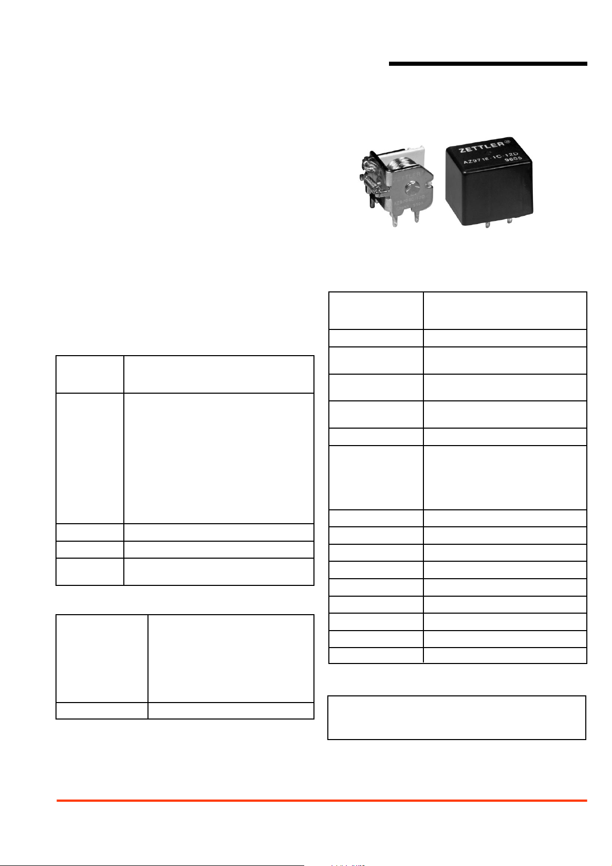
40 AMP MINIATURE
POWER RELAY FOR
AUTOMOTIVE USE
FEATURES
• Low cost
• Up to 40 Amp switching capability in a compact size
• Open, covered or sealed
• Coils to 24 VDC
• Small footprint (European style)
• 1 Form A, B and C contacts available
• Vibration and shock resistant
• Designed for high in-rush applications
COIL
Power
At Pickup Voltage 514 mW (12 and 24 VDC Coil)
(typical) 573 mW (6 VDC Coil)
Max. Continuous 4.8 W 20°C (68°F) ambient (AZ970E)
Dissipation 3.8 W 20°C (68°F) ambient (AZ971E)
Temperature Rise 60°C (108°F) nominal coil VDC (AZ970E)
75°C (135°F) nominal coil VDC (AZ971E)
Max. Temperature 200°C (392°F)
NOTES
1. All values at 20°C (68°F).
2. Relay may pull in with less than “Must Operate” value.
3. Specifications subject to change without notice.
1998-10-27
ZETTLERelectronics
Telephone +44 (0) 1582 599 600 Fax +44 (0) 1582 599 700
Logistic Design (UK) Limited. Unit 3, Eagle Centre Way, Luton LU4 9US www.zettlerrelay.com sales@zettlerrelay.com
AZ970E/AZ971E
RELAY ORDERING DATA — AZ971E — With Dust Cover
COIL SPECIFICATIONS ORDER NUMBER*
Nominal Coil Must Operate Max. Continuous Coil Resistance Form A Form B Form C
VDC VDC VDC ±10% (SPST) (SPST) (SPDT)
6 3.3 8.1 19.0 AZ971E–1A–6D AZ971E–1B–6D AZ971E–1C–6D
9 5.1 14.7 50.0 AZ971E–1A–9D AZ971E–1B–9D AZ971E–1C–9D
12 6.8 17.6 90.0 AZ971E–1A–12D AZ971E–1B–12D AZ971E–1C–12D
24 13.9 35.4 362.0 AZ971E–1A–24D AZ971E–1B–24D AZ971E–1C–24D
*Add suffix “E” for epoxy sealed version.
RELAY ORDERING DATA — AZ970E — OPEN STYLE
COIL SPECIFICATIONS ORDER NUMBER
Nominal Coil Must Operate Max. Continuous Coil Resistance Form A Form B Form C
VDC VDC VDC ±10% (SPST) (SPST) (SPDT)
6 3.3 9.0 19.0 AZ970E–1A–6D AZ970E–1B–6D AZ970E–1C–6D
9 5.1 14.7 50.0 AZ970E–1A–9D AZ970E–1B–9D AZ970E–1C–9D
12 6.8 19.6 90.0 AZ970E–1A–12D AZ970E–1B–12D AZ970E–1C–12D
24 13.9 39.3 362.0 AZ970E–1A–24D AZ970E–1B–24D AZ970E–1C–24D
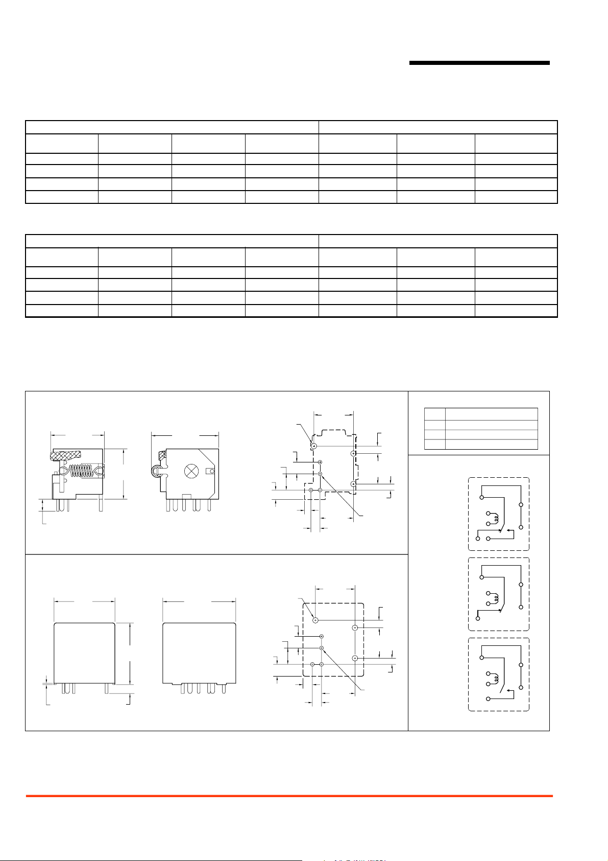
MECHANICAL DATA
Dimensions in inches with metric equivalents in parentheses. Tolerance: ±0.010"
AZ970E Outline Dimensions and PCB Layout
3x ø.081
[ø2.1]
.165
[4.2]
.232
[5.9]
.134
[3.4]
.090
[2.3]
.130
[3.3]
Viewed towards terminals
3x ø.081
[ø2.1]
.165
[4.2]
.232
[5.9]
.170
[4.3]
.134
[3.4]
.130
[3.3]
Viewed towards terminals
.170
[4.3]
.760
[19.3]
.715
[18.2]
.945
[24]
AZ971E Outline Dimensions and PCB Layout
.866
[22]
.878
[22.3]
.020
[.5]
.126
[3.2]
1.040
[26.4]
.563
[14.3]
.476
[12.1]
.563
[14.3]
.476
[12.1]
.433
[11]
.087
[2.2]
4x ø.055
[ø1.4]
.433
[11]
.087
[2.2]
4x ø.055
[ø1.4]
.106
[2.7]
.106
[2.7]
Terminal Dimensions
Dimensions
Term.
3,5
.041 [1.02] x .03 [0.76]
1,2
.041 [1.02] x .018 [0.46]
4 .041 [1.02] x .062 [1.57]
Wiring Diagrams
4
FORM C
FORM B
FORM A
2
1
3
5
4
2
1
3
4
2
1
5
Viewed towards terminals
4
4
4
4
4
4
 Loading...