


ZETTLER AZ954Y-1C-9DS, AZ954X-1C-3DS, AZ954X-1C-3DM, AZ954X-1C-3D, AZ954X-1C-24DS Datasheet
...
GENERAL DATA
Life Expectancy Minimum operations
Mechanical 1 x 10
7
Electrical 1 x 10⁵at rated load
Operate Time (typical) 5 ms at nominal coil voltage
Release Time (typical) 1 ms at nominal coil voltage
(with no coil suppressions)
Dielectric Strength 1250 Vrms coil to contact
(at sea level for 1 min.) 750 Vrms between open contacts
Insulation Resistance 100 megohms min. at 20°C, 500 VDC
Dropout Greater than 10% of nominal coil voltage
Ambient Temperature At nominal coil voltage
Operating 0.45W: -25°C (-13°F) to 55°C (131°F)
0.36W: -25°C (-13°F) to 65°C (167°F)
0.2W: -25°C (-13°F) to 75°C (167°F)
Storage -25°C (-13°F) to 105°C (221°F)
Vibration 0.062" DA at 10–55Hz
Shock 15 g
Enclosure P.B.T. polyester
Terminals Tinned copper alloy
Max. Solder Temp. 270°C (518°F)
Max. Solder Time 5 seconds
Max. Solvent Temp. 80°C (176°F)
Max. Immersion Time 30 seconds
Weight 3.5 grams
COIL
Power
At Pickup Voltage 0.45W coil: 253 mW
(typical) 0.36W coil: 203 mW
0.2W coil: 114 mw
Max Continuous 0.8 W at 20°C (68°F) ambient
Dissipation 0.6 W at 40°C (104°F) ambient
Temperature Rise At nominal coil voltage:
0.45W: 54°C (97°F)
0.36W: 44°C (79°F)
0.2W: 30°C (54°F)
Max. Temperature 105°C (221°F)
CONTACTS
Arrangement SPDT (1 Form C)
Ratings Resistive load:
Light Duty Max. switched power: 30 W or 125 VA
Max. switched current: 1 A
Max. switched voltage:150 VDC* or 300 VAC
UL Rating: 1 A at 125 VAC General Use
1 A at 30 VDC Resistive
Medium Duty Max. switched power: 30 W or 250 VA
Max. switched current: 2 A
Max. switched voltage:150 VDC* or 300 VAC
UL Rating: 2 A at 125VAC General Use
1 A at 30 VDC Resistive
.
Material Silver alloy
Resistance < 100 milliohms initially
ZETTLERelectronics
Telephone +44 (0) 1582 599 600 Fax +44 (0) 1582 599 700
Logistic Design (UK) Limited. Unit 3, Eagle Centre Way, Luton LU4 9US www.zettlerrelay.com sales@zettlerrelay.com
2000-06-06
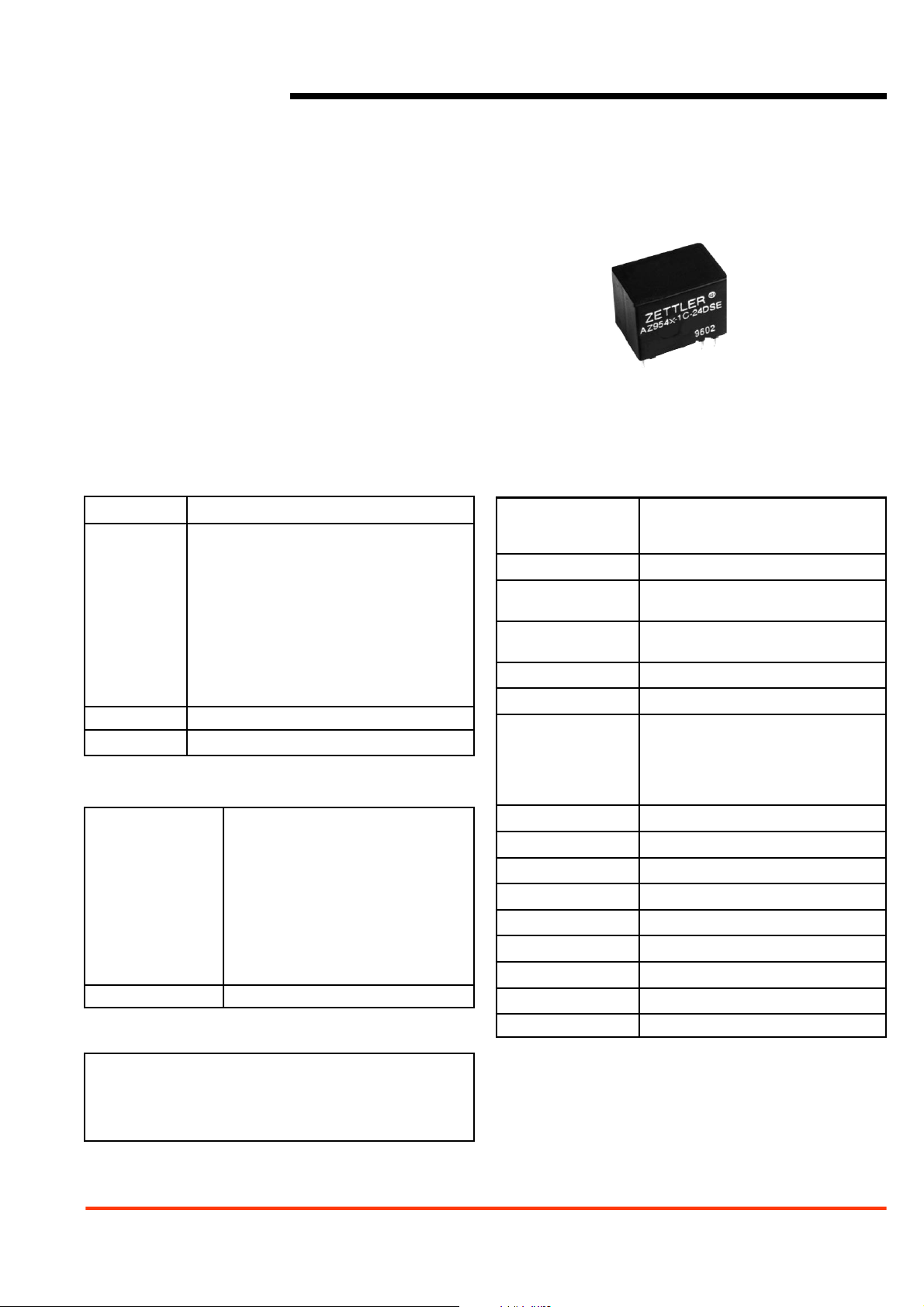
AZ954
SUBMINIATURE
POWER RELAY
FEATURES
• Subminiature size for high density packaging
• Coil sensitivity to 114 mW
• Extremely low cost
• Coils to 24 VDC
• Epoxy sealed for automatic wave soldering
• 2 Amp contacts
• Class B and F insulation available
• Life expectancy to 10 million operations
• UL, CUR file E43203
NOTES
1. All values at 20°C (68°F).
2. Relay may pull in with less than “Must Operate” value.
3. Other coil resistances and sensitivities available upon request.
4. Specifications subject to change without notice.
2000-06-06
ZETTLERelectronics
Telephone +44 (0) 1582 599 600 Fax +44 (0) 1582 599 700
Logistic Design (UK) Limited. Unit 3, Eagle Centre Way, Luton LU4 9US www.zettlerrelay.com sales@zettlerrelay.com
AZ954
RELAY ORDERING DATA
MEDIUM DUTY RELAYS – 0.45 W COIL
COIL SPECIFICATIONS
Nominal Coil Max. Continuous Coil Resistance Must Operate
ORDER NUMBER*
VDC VDC ±10% VDC
3 4.0 20 2.25 AZ954X–1C–3D AZ954Y–1C–3D
5 6.7 56 3.75 AZ954X–1C–5D AZ954Y–1C–5D
6 8.0 80 4.50 AZ954X–1C–6D AZ954Y–1C–6D
9 12.0 180 6.75 AZ954X–1C–9D AZ954Y–1C–9D
12 16.0 320 9.0 AZ954X–1C–12D AZ954Y–1C–12D
24 32.0 1280 18.0 AZ954X–1C–24D AZ954Y–1C–24D
MEDIUM DUTY RELAYS – 0.36 W COIL
COIL SPECIFICATIONS
Nominal Coil Max. Continuous Coil Resistance Must Operate
ORDER NUMBER*
VDC VDC ±10% VDC
3 4.5 25 2.25 AZ954X–1C–3DM AZ954Y–1C–3DM
5 7.5 70 3.75 AZ954X–1C–5DM AZ954Y–1C–5DM
6 8.9 100 4.50 AZ954X–1C–6DM AZ954Y–1C–6DM
9 13.4 225 6.75 AZ954X–1C–9DM AZ954Y–1C–9DM
12 17.8 400 9.0 AZ954X–1C–12DM AZ954Y–1C–12DM
24 35.7 1600 18.0 AZ954X–1C–24DM AZ954Y–1C–24DM
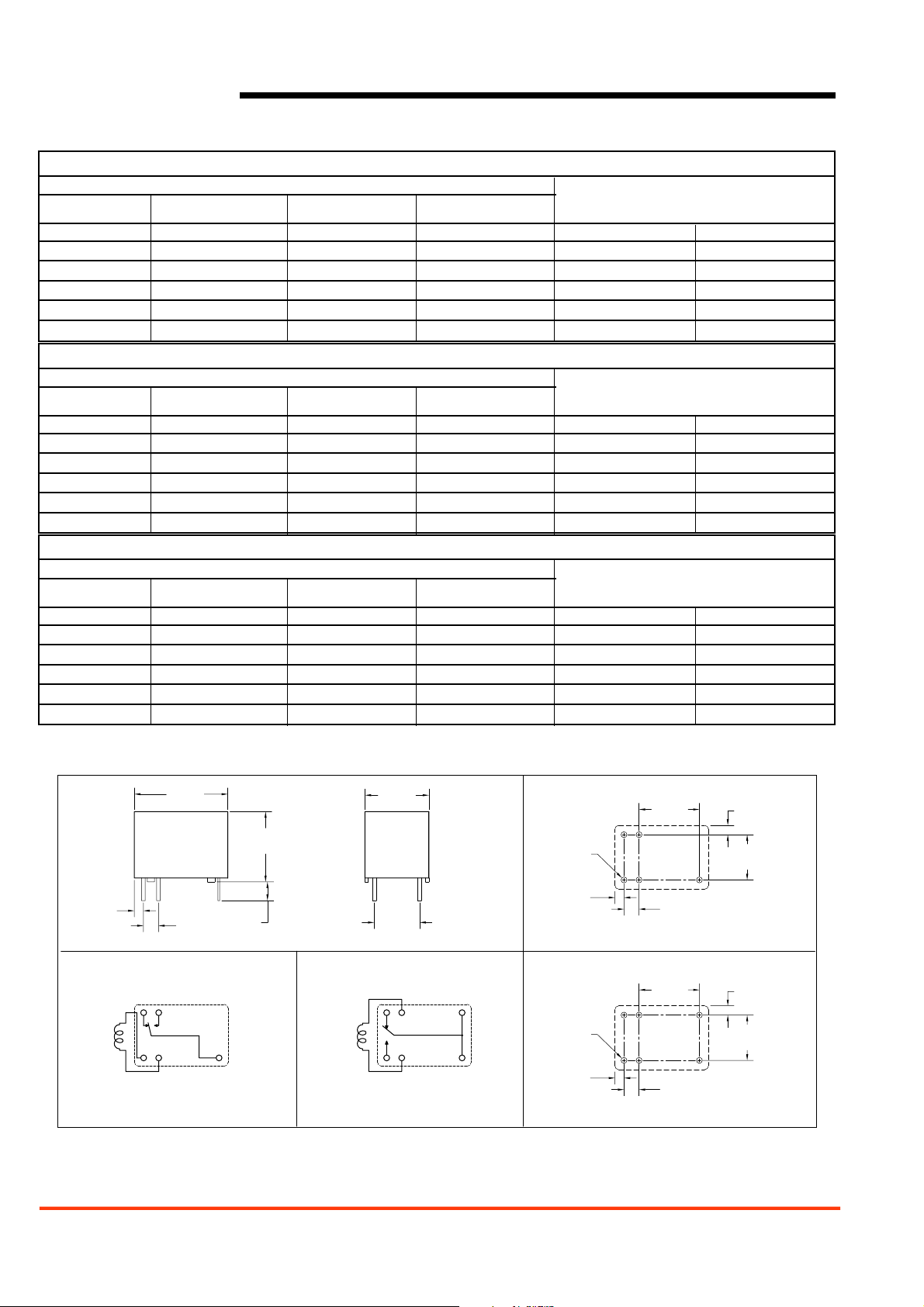
MECHANICAL DATA
Dimensions in inches with metric equivalents in parentheses. Tolerance: ±0.010"
LIGHT DUTY RELAYS – 0.2 W COIL
COIL SPECIFICATIONS
Nominal Coil Max. Continuous Coil Resistance Must Operate
ORDER NUMBER*
VDC VDC ±10% VDC
3 6.0 45 2.25 AZ954X–1C–3DS AZ954Y–1C–3DS
5 9.8 120 3.75 AZ954X–1C–5DS AZ954Y–1C–5DS
6 12.0 180 4.50 AZ954X–1C–6DS AZ954Y–1C–6DS
9 17.8 400 6.75 AZ954X–1C–9DS AZ954Y–1C–9DS
12 23.6 700 9.0 AZ954X–1C–12DS AZ954Y–1C–12DS
24 47.3 2800 18.0 AZ954X–1C–24DS AZ954Y–1C–24DS
*Add suffix “E” for epoxy sealed version. Add suffix “B” for Class B or “F” for Class F insulation system.
.620
[15.75]
.465
[11.81]
.060
[1.52]
AZ954X WIRING DIAGRAM
VIEWED TOWARD TERMINALS
.100
[2.54]
2
1
1112
.125
[3.18]
7
.423
[10.75]
.300
[7.62]
AZ954Y WIRING DIAGRAM
2
1
11
12
VIEWED TOWARD TERMINALS
AZ954X PC BOARD LAYOUT
.400
[10.16]
5x ø.039±.005
[ø1.0]
.060
[1.52]
VIEWED TOWARD TERMINALS
AZ954Y PC BOARD LAYOUT
6
7
6x ø.039±.005
[ø1.0]
.060
[1.52]
VIEWED TOWARD TERMINALS
.100
[2.54]
.400
[10.16]
.100
[2.54]
.062
[1.56]
.300
[7.62]
.062
[1.56]
.300
[7.62]
 Loading...