


ZETTLER AZ6961-1C-48D, AZ6961-1C-24D, AZ6961-1C-12D, AZ6961-1A-6D, AZ6961-1C-6D Datasheet
...
ZETTLERelectronics
Telephone +44 (0) 1582 599 600 Fax +44 (0) 1582 599 700
Logistic Design (UK) Limited. Unit 3, Eagle Centre Way, Luton LU4 9US www.zettlerrelay.com sales@zettlerrelay.com
2001-02-01
AZ6961
8 AMP SUBMINIATURE
POWER RELAY
FEATURES
• High sensitivity, 120 mW pickup
• Dielectric strength 5000 Vrms
• Isolation spacing greater than 8 mm
• 8 Amp switching capability
• Class B insulation standard, Class F version available
• Epoxy sealed version for automatic wave soldering and
cleaning available
• UL, CUR, file E43203
• VDE 131637ÜG
GENERAL DATA
Life Expectancy Minimum operations
Mechanical 10 million
Electrical 1 X 10⁵at 8 A 240 VAC res.
Operate Time (typical) 7 ms at nominal coil voltage
Release Time (typical) 3 ms at nominal coil voltage
(with no coil suppression)
Dielectric Strength 5000 Vrms coil to contact
(at sea level for 1 min.) 1000 Vrms between open contacts
Insulation 1000 megohms min. at 20°C, 500 VDC,
Resistance 50% RH
Insulation C250
(according to Overvoltage category: III
DIN VDE 0110, Pollution degree: 3
IEC 60664-1) Nominal voltage: 250 VAC
Dropout Greater than 10% of nominal coil voltage
Ambient Temperature At nominal coil voltage
Operating -40°C (-40°F) to 85°C (185°F)
Storage -40°C (-40°F) to 85°C (185°F)
Vibration Break Contact: 5 g at 10 …500 Hz
Make Contact: 20 g at 10…500 Hz
Shock 10 g
Enclosure P.B.T. polyester, UL94 V-O
Terminals Tinned copper alloy, P.C.
Max. Solder Temp. 270°C (518°F)
Max. Solder Time 5 seconds
Max. Solvent Temp. 80°C (176°F)
Max. Immersion Time 30 seconds
Weight 8 grams
CONTACTS
Arrangement SPDT (1 Form C)
SPST (1 Form A)
Ratings Resistive load:
Max. switched power: 240 W or 2000 VA
Max. switched current: 8 A
Max. switched voltage:240* VDC or 440 VAC
UL, CUR Rating: 8 A at 30 VDC / 250 VAC
VDE Rating: 8 A at 250 VAC
*Note: If switching voltage is greater than 30VDC, special
precautions must be taken. Please contact the factory.
Material Silver cadmium oxide
Silver tin oxide available upon request
Resistance < 100 milliohms initially
NOTES
1. All values at 20°C (68°F).
2. Relay may pull in with less than “Must Operate” value.
3. Specifications subject to change without notice.
4. Class F version not VDE approved.
COIL
Power
At Pickup Voltage 120 mW
(typical)
Max. Continuous 1.4 W at 20°C (68°F) ambient
Dissipation 1.1 W at 40°C (104°F) ambient
Temperature Rise 20°C (36°F) at nominal coil voltage
Temperature Max. 130°C (266°F)
2001-02-01
ZETTLERelectronics
Telephone +44 (0) 1582 599 600 Fax +44 (0) 1582 599 700
Logistic Design (UK) Limited. Unit 3, Eagle Centre Way, Luton LU4 9US www.zettlerrelay.com sales@zettlerrelay.com
AZ6961
RELAY ORDERING DATA
COIL SPECIFICATIONS ORDER NUMBER*
Nominal Coil Max. Continuous Coil Resistance Must Operate 1 Form A 1 Form C
VDC VDC VDC (SPST-NO) (SPDT)
5 11.8 113 ± 10% 3.5 AZ6961–1A–5D AZ6961–1C–5D
6 14.1 164 ± 10% 4.2 AZ6961–1A–6D AZ6961–1C–6D
12 28.2 617 ± 10% 8.4 AZ6961–1A–12D AZ6961–1C–12D
24 56.4 2350 ± 10% 16.8 AZ6961–1A–24D AZ6961–1C–24D
48 112.8 9600 ± 15% 33.6 AZ6961–1A–48D AZ6961–1C–48D
60 141.0 12500 ± 15% 42.0 AZ6961–1A–60D AZ6961–1C–60D
*Add suffix “E” for sealed version. Add suffix “F” for Class F version.
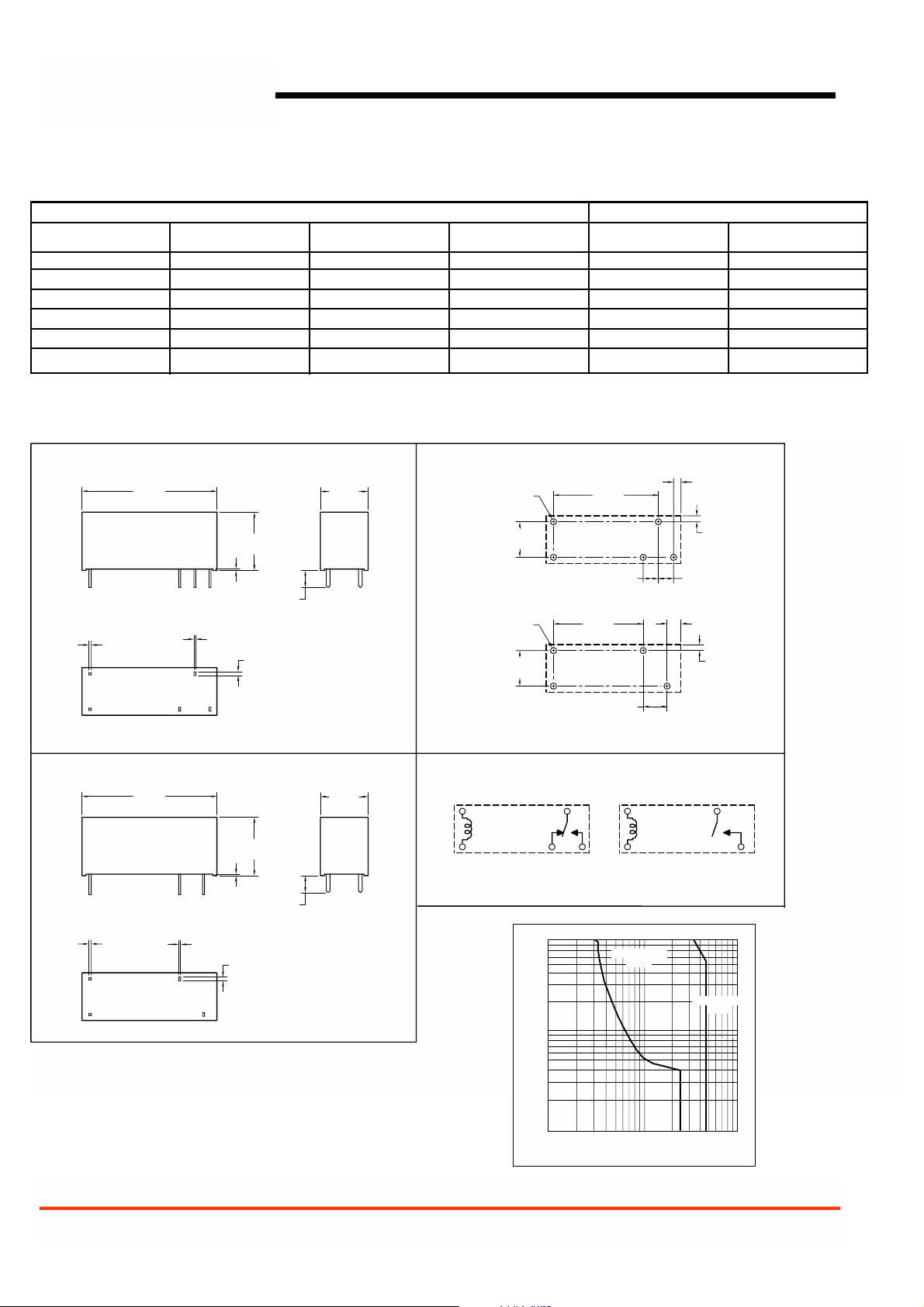
MECHANICAL DATA
Maximum Switching Capacity
Dimensions in inches with metric equivalents in parentheses. Tolerance: ± .010"
FORM C VERSION
2 x .020
[0.5]
FORM A VERSION
2 x .020
[0.5]
1.122
[28.5]
1.122
[28.5]
2 x .016
[0.4]
3 x .016
[0.4]
.012
[0.3]
.012
[0.3]
2 x .031
[0.8]
.484
[12.3]
3 x .031
[0.8]
.484
[12.3]
.142
[3.6]
.142
[3.6]
.398
[10.1]
.398
[10.1]
PC BOARD LAYOUT
CIRCUIT DIAGRAM
5 x ø.051
[ø1.3]
.298
[7.56]
4 x ø.051
[ø1.3]
.298
[7.56]
14
FORM C
235
VIEWED TOWARD TERMINALS
.870
[22.1]
FORM C
.126
[3.2]
.744
[18.9]
FORM A
.198
[5.04]
VIEWED TOWARD TERMINALS
13
24
FORM A
8.0
7.0
6.0
5.0
4.0
3.0
2.0
1.0
.9
.8
.7
CURRENT
.6
.5
.4
.3
.2
DC Resistive
Load
.062
[1.57]
.050
[1.3]
.126
[3.2]
.116
[2.95]
.050
[1.3]
AC Resistive
Load
.1
203040
50
10
708090
60
VOLTAGE
200
300
400
500
700
800
900
100
600
1000
 Loading...