


ZETTLER AZ942-1CT-9D, AZ942-1CT-6DE, AZ942-1CT-6D, AZ942-1CT-5DE, AZ942-1CT-9DE Datasheet
...
ZETTLERelectronics
Telephone +44 (0) 1582 599 600 Fax +44 (0) 1582 599 700
Logistic Design (UK) Limited. Unit 3, Eagle Centre Way, Luton LU4 9US www.zettlerrelay.com sales@zettlerrelay.com
200-06-09
AZ942
CONTACTS
Arrangement SPST (1 Form A)
SPDT (1 Form C)
Ratings Resistive load
Medium Duty Max. switched power: 150 W or 2770 VA
Max. switched current: 10 A
Max. switched voltage:30 VDC or 300 VAC
UL Rating: 5 A at 30 VDC
10 A at 277 VAC
1/3 HP at 125 VAC (1 Form A)
2.9 A 125 VAC pilot duty (1 Form A)
Heavy Duty Max. switched power: 480 W or 4000 VA
Max. switched current: 16 A
Max. switched voltage:30 VDC or 300 VAC
UL Rating:12 A at 28 VDC
12 A at 277 VAC
16A at 250 VAC
2.0 A at 240 VAC pilot duty
Material Silver alloy
Resistance <100 milliohms initially
(24 V, 1 A voltage drop method)
COIL
Power
At Pickup Voltage 230 mW
(typical)
Max Continuous Class B: 1.7 W at 20°C (68°F) ambient
Dissipation Class F: 2.2 W at 20°C (68°F) ambient
Temperature Rise 25°C (45°F) at nominal coil voltage
Temperature Class B: Max. 130°C (266°F)
Class F: Max. 155°C (311°F)
GENERAL DATA
Life Expectancy Minimum operations
Mechanical 1x10
7
Electrical 1 x 10⁵at 10A, 277 VAC
Operate Time (typical) 10 ms at nominal coil voltage
Release Time (typical) 5 ms at nominal coil voltage
(with no coil suppression)
Dielectric Strength 1750 Vrms contact to coil
(at sea level for 1 min.) 1000 Vrms across contacts
Insulation Resistance 100 megohms min. at 20°C, 500 VDC,
50% RH
Dropout Greater than 10% of nominal coil voltage
Ambient Temperature At nominal coil voltage
Operating Class B: -40°C(-40°F) to 105°C(221°F)
Class F: -40°C(-40°F) to 130°C(266°F)
Storage Class B: -55°C(-67°F) to 130°C(266°F)
Class F: -55°C(-67°F) to 155°C(311°F)
Vibration 0.062" DA at 10–55Hz
Shock 10 g
Enclosure P.B.T. polyester
Terminals Tinned copper alloy, P.C.
Max. Solder Temp. 270°C (518°F)
Max. Solder Time 5 seconds
Max. Solvent Temp. 80°C (176°F)
Max. Immersion Time 30 seconds
Weight 13 g
16 AMP
MINIATURE
PC BOARD RELAY
FEATURES
• Extremely low cost
• High switching capacity — 16 Amps
• DC coils to 48 VDC
• UL, CUR file E44211; VDE file 6820
• Class B insulation for high temperature operation
• Class F insulation available
5
NOTES
1. All values at 20°C (68°F).
2. Relay may pull in with less than “Must Operate” value.
3. Unsealed relays should not be dip cleaned.
4. Specifications subject to change without notice.
AZ942-1CT unsealed version is VDE approved at 5 A,
250 VAC, 50,000 operations. AZ942-1CT sealed or unsealed
version is VDE approved at 7 A, 250 VAC, 6,000 operations.
5
RELAY ORDERING DATA
STANDARD RELAYS: Medium Duty Type (10 Amp Contact)
COIL SPECIFICATIONS ORDER NUMBER*
Nominal Coil Max. Continuous Coil Resistance Must Operate
Unsealed Sealed
VDC VDC ±10% VDC
3 6.5 25 2.4 AZ942–1CH–3D AZ942–1CH–3DE
5 11.0 70 4.0 AZ942–1CH–5D AZ942–1CH–5DE
6 13.0 100 4.8 AZ942–1CH–6D AZ942–1CH–6DE
9 20.0 225 7.2 AZ942–1CH–9D AZ942–1CH–9DE
12 26.0 400 9.6 AZ942–1CH–12D AZ942–1CH–12DE
24 52.0 1,600 19.2 AZ942–1CH–24D AZ942–1CH–24DE
48 104.0 6,200 38.4 AZ942–1CH–48D AZ942–1CH–48DE
*Substitute “1AT” in place of “1CH” to indicate 1 Form A contact. To indicate Class F version, add suffix “F.”
RELAY ORDERING DATA
STANDARD RELAYS: Heavy Duty Type (16 Amp Contact)
COIL SPECIFICATIONS ORDER NUMBER*
Nominal Coil Max. Continuous Coil Resistance Must Operate
Unsealed Sealed
VDC VDC ±10% VDC
3 6.5 25 2.4 AZ942–1CT–3D AZ942–1CT–3DE
5 11.0 70 4.0 AZ942–1CT–5D AZ942–1CT–5DE
6 13.0 100 4.8 AZ942–1CT–6D AZ942–1CT–6DE
9 20.0 225 7.2 AZ942–1CT–9D AZ942–1CT–9DE
12 26.0 400 9.6 AZ942–1CT–12D AZ942–1CT–12DE
24 52.0 1,600 19.2 AZ942–1CT–24D AZ942–1CT–24DE
48 104.0 6,200 38.4 AZ942–1CT–48D AZ942–1CT–48DE
*Substitute “1AW” in place of “1CT” to indicate 1 Form A contact. To indicate Class F version, add suffix “F.”
200-06-09
ZETTLERelectronics
Telephone +44 (0) 1582 599 600 Fax +44 (0) 1582 599 700
Logistic Design (UK) Limited. Unit 3, Eagle Centre Way, Luton LU4 9US www.zettlerrelay.com sales@zettlerrelay.com
AZ942
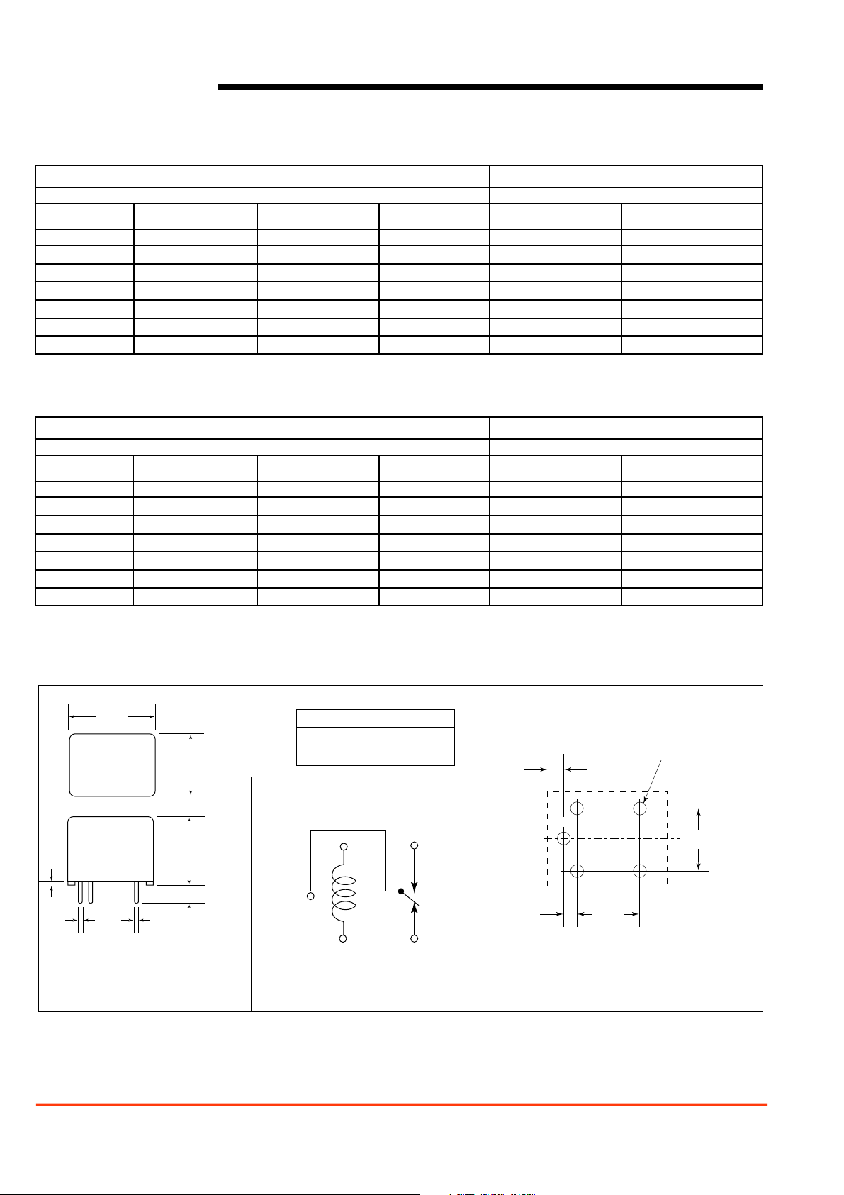
MECHANICAL DATA
Dimensions in inches with metric equivalents in parentheses. Tolerance: ±0.010"
.89
(22.5)
.65
(16.5)
TERMINAL DIMENSIONS
Ter minal Number
1
2, 5
3, 4
Dimensions
.013 X .040
.013 X .036
.013 X .040
WIRING DIAGRAM
016
0.4)
.013
(0.3)
(16.5)
.040
(1.0)
5 PLACES
.65
2
1
.138
(3.5)
5
Viewed toward terminals
*Not used on Form A relay
PC BOARD LAYOUT
.05
5 HOLES
.082
(2.1)
C
3
4*
L
.078
(2.0)
Viewed toward terminals
.480
(12.2)
*Not used on Form A relay
(1.3)
.472
(12.0)
*
 Loading...