


ZETTLER AZ763-1C-48DE, AZ763-1C-48D, AZ763-1C-3DE, AZ763-1C-3D, AZ763L-1C-60D Datasheet
...
GENERAL DATA
Life Expectancy Minimum operations
Mechanical 3 x 10
7
Electrical 1 x 10⁵at 12 A 240 VAC res.
Operate Time (typical) 7 ms at nominal coil voltage
Release Time (typical) 3 ms at nominal coil voltage
(with no coil suppression)
Dielectric Strength 5000 Vrms coil to contact
(at sea level for 1 min.) 1000 Vrms between open contacts
Insulation 105megohms min. at 20°C
Resistance 500 VDC 50% RH
Insulation B250 at 2 Form C, unsealed
(according to C250 at other relay versions
DIN VDE 0110, Overvoltage category: III
IEC 60664-1) Pollution degree: 3
Nominal voltage: 250 VAC
Dropout Greater than 10% of nominal coil voltage
Ambient Temperature At nominal coil voltage
Operating -40°C (-40°F) to 85°C (185°F)
Storage -40°C (-40°F) to 85°C (185°F)
Vibration Break contacts: 5 g at 20…500 Hz
Make contacts: 20 g at 30…500 Hz
Shock 30 g
Enclosure P.B.T. polyester, UL-94 : V0
Terminals Tinned copper alloy, P.C.
Max. Solder Temp. 270°C (518°F)
Max. Solder Time 5 seconds
Max. Solvent Temp. 80°C (176°F)
Max. Immersion Time 30 seconds
Weight 14 grams
ZETTLERelectronics
Telephone +44 (0) 1582 599 600 Fax +44 (0) 1582 599 700
Logistic Design (UK) Limited. Unit 3, Eagle Centre Way, Luton LU4 9US www.zettlerrelay.com sales@zettlerrelay.com
2001-02-01
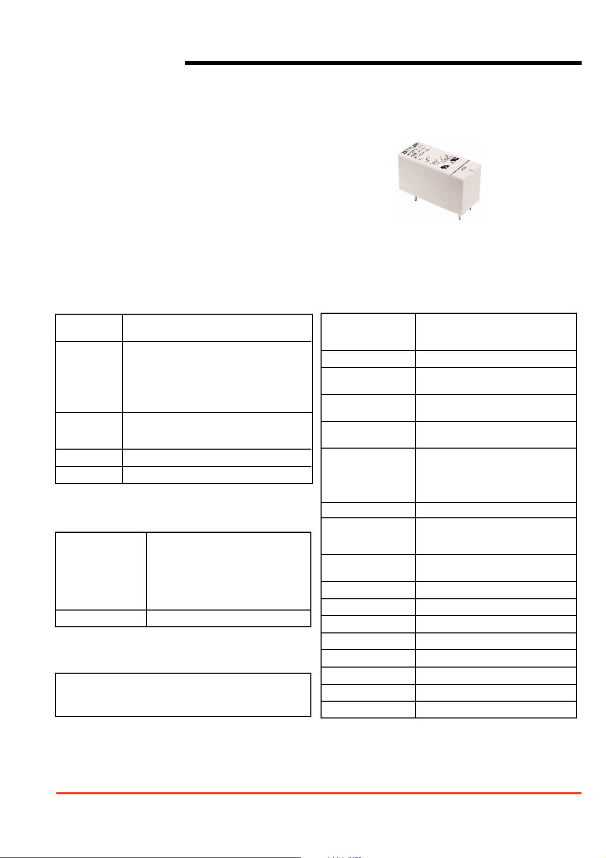
AZ763
12 A SPDT MINIATURE
POWER RELAY
FEATURES
• Dielectric strength 5000 Vrms
• Low height: 15.7 mm
• Epoxy sealed version available
• 12 Amp switching
• Isolation spacing greater than 10mm
• Proof tracking index (PTI/CTI) 250
• Surpasses requirements of VDE 0631/0700
• UL, CUR file E43203; VDE 112904
COIL
Power
At Pickup Voltage 200 mW
(typical)
Max. Continuous 2.4 W at 20°C (68°F) ambient
Dissipation 2.1 W at 40°C (104°F) ambient
Temperature Rise 14°C (25°F) at nominal coil voltage
Max. Temperature 115°C (239°F)
NOTES
1. All values at 20°C (68°F).
2. Relay may pull in with less than “Must Operate” value.
3. Specifications subject to change without notice.
CONTACTS
Arrangement SPDT (1 Form C)
SPST (N.O.) (1 Form A)
Ratings Resistive load:
Max. switched power: 360 W or 3000 VA
Max. switched current: 12 A
Max. switched voltage:300* VDC or 400 VAC
*Note: If switching voltage is greater than 30 VDC, special
precautions must be taken. Please contact the factory.
Rated Load
UL, CUR 12 A at 250 VAC general use
VDE 12 A at 250 VAC
Material AgNi or AgNi gold plated
Resistance < 100 milliohms initially
2001-02-01
ZETTLERelectronics
Telephone +44 (0) 1582 599 600 Fax +44 (0) 1582 599 700
Logistic Design (UK) Limited. Unit 3, Eagle Centre Way, Luton LU4 9US www.zettlerrelay.com sales@zettlerrelay.com
AZ763
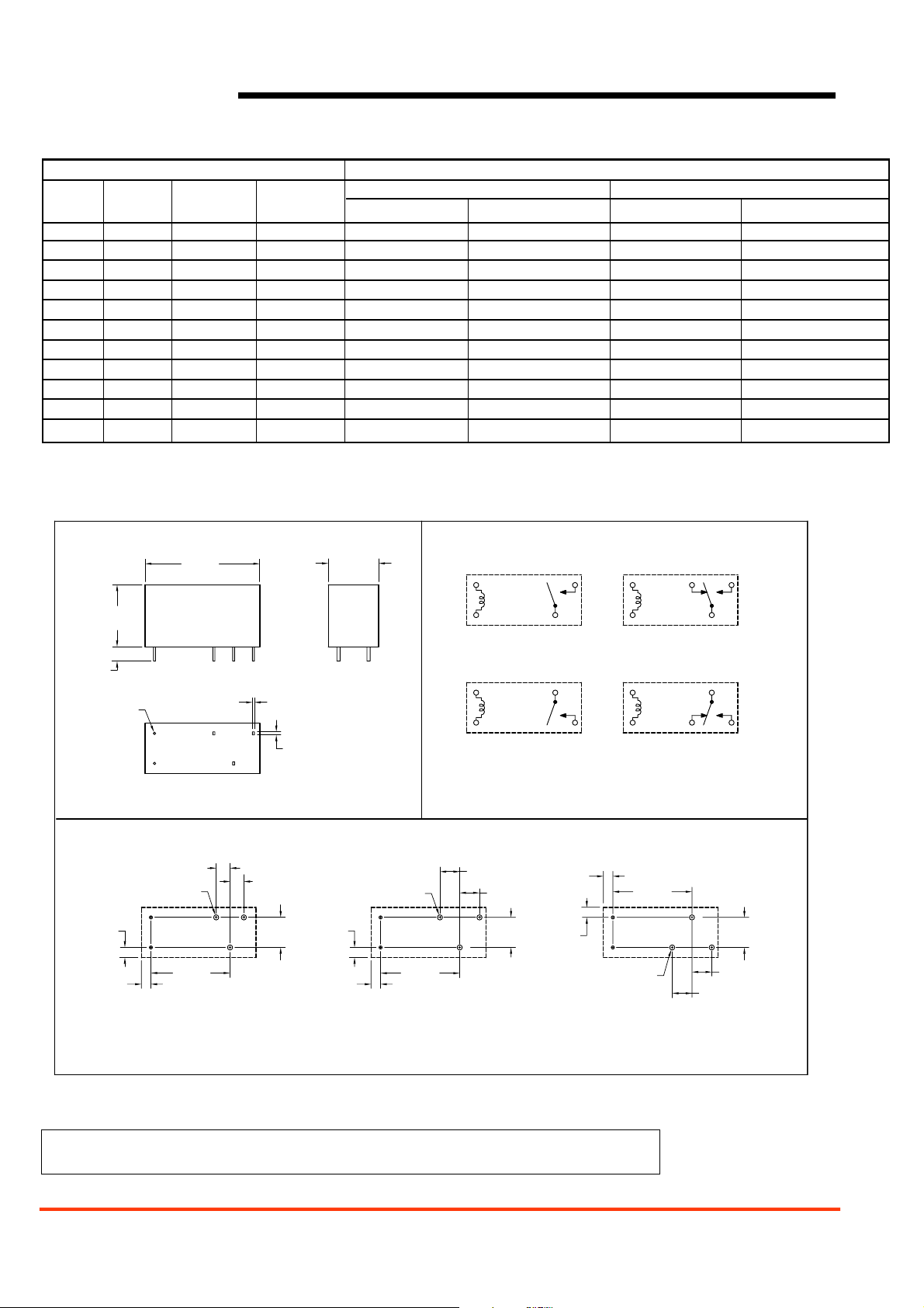
MECHANICAL DATA
Hardware
For PCB mount: Socket EC35 (version R and L : EC50) – Retaining clip MP16 / MH16
For DIN coil mount: Socket ES35 (version R and L : ES50) – Retaining clip MS16
RELAY ORDERING DATA
COIL SPECIFICATIONS ORDER NUMBER*
Nominal Must Max. Coil
Unsealed Sealed
Coil Operate Continuous Resistance
3.5 mm STD 5 mm STD Left 3.5mm 5 mm STD Left
VDC VDC VDC ± 10%
3 2.1 7.6 22 AZ763–1C–3D AZ763L–1C–3D AZ763–1C–3DE AZ763L–1C–3DE
5 3.5 12.7 60 AZ763–1C–5D AZ763L–1C–5D AZ763–1C–5DE AZ763L–1C–5DE
6 4.2 15.3 90 AZ763–1C–6D AZ763L–1C–6D AZ763–1C–6DE AZ763L–1C–6DE
9 6.3 22.9 200 AZ763–1C–9D AZ763L–1C–9D AZ763–1C–9DE AZ763L–1C–9DE
12 8.4 30.6 360 AZ763–1C–12D AZ763L–1C–12D AZ763–1C–12DE AZ763L–1C–12DE
18 12.6 45.9 710 AZ763–1C–18D AZ763L–1C–18D AZ763–1C–18DE AZ763L–1C–18DE
24 16.8 61.2 1,440 AZ763–1C–24D AZ763L–1C–24D AZ763–1C–24DE AZ763L–1C–24DE
36 25.2 92 3,140 AZ763–1C–36D AZ763L–1C–36D AZ763–1C–36DE AZ763L–1C–36DE
48 33.6 122.0 5,700 AZ763–1C–48D AZ763L–1C–48D AZ763–1C–48DE AZ763L–1C–48DE
60 42.0 153.0 7,500 AZ763–1C–60D AZ763L–1C–60D AZ763–1C–60DE AZ763L–1C–60DE
110 77.0 280.0 25,200 AZ763–1C–110D AZ763L–1C–110D AZ763–1C–110DE AZ763L–1C–110DE
*For 5 mm “Right” spacing substitute “AZ763L” with “AZ763R”. “1C” : 1 Form C, contact material AgNi; “1A” : 1 Form A, contact material AgNi;
“1CG” : 1 Form C, contact material AgNi gold plated; “1AG” : 1 Form A, contact material AgNi gold plated.
Dimensions in inches with metric equivalents in parentheses. Tolerance: ± .010"
.618
Max.
[15.7]
.154
[3.9]
2 x ø.024
[ø0.6]
PC BOARD LAYOUT
.098
[2.5]
.098
[2.5]
3.5mm SPACING
* Not used on 1 Form A relay
.500
1.142
Max.
[29.0]
3 x .020
[0.5]
3 x .035
[0.9]
.138
[3.5]
5 x ø.051
[ø1.3]
.787
[20.0]
1 FORM C
.138
[3.5]
**
.295
[7.5]
Max.
[12.7]
5 x ø.051
[ø1.3]
.098
[2.5]
.098
[2.5]
5.0mm LEFT SPACING
VIEWED TOWARD TERMINALS
WIRING DIAGRAM
.787
[20.0]
AZ763LAZ763
1 FORM C
12
54
1 FORM A
STANDARD & LEFT
54
13
1 FORM A
RIGHT
VIEWED TOWARD TERMINALS
.197
[5.0]
.197
[5.0]
.295
[7.5]
.098
.098
[2.5]
[2.5]
5.0mm RIGHT SPACING
123
54
1 FORM C
STANDARD & LEFT
54
123
1 FORM C
RIGHT
.787
[20.0]
.295
.197
[5.0]
.197
[5.0]
[7.5]
5 x ø.051
[ø1.3]
AZ763R
1 FORM C
*
 Loading...