

Page 1

Machine Controller MP2000 Series
USER’S MANUAL
for Motion Programming
MANUAL NO. SIEP C880700 38C
Overview
Specifications
Program Development Flow
Motion Programs
Sequence Programs
Variables (Registers)
Programming
Command Reference
Engineering Tool MPE720
Troubleshooting
Appendices
1
2
3
4
5
6
7
8
9
10
App
Page 2

Copyright © 2008 YASKAWA ELECTRIC CORPORATION
All rights reserved. No part of this publication may be reproduced, stored in a retrieval system,
or transmitted, in any form, or by any means, mechanical, electronic, photocopying, recording,
or otherwise, without the prior written permission of Yaskawa. No patent liability is assumed
with respect to the use of the information contained herein. Moreover, because Yaskawa is constantly striving to improve its high-quality products, the information contained in this manual is
subject to change without notice. Every precaution has been taken in the preparation of this
manual. Nevertheless, Yaskawa assumes no responsibility for errors or omissions. Neither is
any liability assumed for damages resulting from the use of the information contained in this
publication.
Page 3

About This Manual
This manual provides information on motion commands for the MP2000 series Machine Control-
lers.
• Motion program overview
• Specifications
• Program development flow
• Motion programs and sequence programs
• Variables
• Programming
• Command reference
• Engineering tool MPE720
• Troubleshooting, etc.
Read this manual carefully to ensure the proper use of the MP2000 series Machine Controller.
Also, keep this manual in a safe place so that it can be referred to whenever necessary.
Using This Manual
Intended Audience
This manual is intended for the following users.
• Those responsible for designing the MP2000 series Machine Controller system
• Those responsible for writing MP2000 series Machine Controller motion programs and sequence programs
Engineering Tool MPE720 Version Number
In this manual, the operation of MPE720 is described using screenshots of MPE720 version 6.
For this reason, the screenshots and some descriptions may differ from those for MPE720 version 5.
Description of Abbreviation
In this manual, the following abbreviation is used.
• MP2000: Machine controller model including MP2100, MP2100M, MP2200, MP2300, MP2300S,
MP2310, MP2400, MP2500, MP2500M, MP2500D, and MP2500MD
Manuals for MP2000 Series
The user’s manuals are prepared by classifying MP2000 series Machine Controller models into
MP2100, MP2100M, MP2200, MP2300, MP2300S, MP2310, MP2400, MP2500, MP2500M,
MP2500D, and MP2500MD.
Refer to Related Manuals on the next page as required.
iii
Page 4

Related Manuals
The following table lists the related manuals. Refer to these manuals as required.
Before using, be sure you understand the product conditions, including specifications and usage
restrictions.
Manual Name Manual Number Contents
Machine Controller MP2100/MP2100M User’s Manual SIEPC88070001
Machine Controller MP2200 User’s Manual SIEPC88070014
Machine Controller MP2300 Basic Module User’s Manual SIEPC88070003
Machine Controller MP2300S Basic Module User’s Manual SIEPC88073200
Machine Controller MP2310 Basic Module
User’s Manual
Machine Controller MP2400 User’s Manual SIJPC88074200
Machine Controller MP2500/MP2500M/MP2500D/
MP2500MD User’s Manual
Machine Controller MP2000 series SVB/SVB-01
Motion Module User's Manual
Machine Controller MP2000 Series Motion Module SVA-01
User’s Manual
Machine Controller MP2000 Series Pulse Output Motion
Module PO-01 User’s Manual
Machine Controller MP2000 Series Communication Module
User’s Manual
Engineering Tool for Machine Controller MP2000 Series
MPE720 Version 6 User’s Manual
Machine Controller MP900/MP2000 Series MPE720
Software for Programming Device User’s Manual
Machine Controller MP900/MP2000 Series User’s Manual,
Ladder Programming
Machine Controller MP900/MP2000 Series
New Ladder Editor User’s Manual
Programming Manual
Machine Controller MP900/MP2000 Series
New Ladder Editor User’s Manual
Operation
SIEPC88073201
SIEPC88075200
SIEPC88070033
SIEPC88070032
SIEPC88070028
SIEPC88070004
SIEPC88070030
SIEPC88070005
SIEZ-C887-1.2
SIEZ-C887-13.1
SIEZ-C887-13.2
Describes the functions, specifications, setup
procedures, and operating methods of the
MP2100/MP2100M.
Describes the functions, specifications, setup
procedures, and operating methods of the
MP2200.
Describes the functions, specifications, setup
procedures, and operating methods of the
MP2300.
Describes the functions, specifications, setup
procedures, and operating methods of the
MP2300S.
Describes the functions, specifications, setup
procedures, and operating methods of the
MP2310.
Describes the functions, specifications, setup
procedures, and operating methods of the
MP2400.
Describes the functions, specifications, setup
procedures, and operating methods of the
MP2500/MP2500M/MP2500D/MP2500MD.
Describes the functions, specifications, and
application methods of the MP2000-series
Motion Module that is built into the SVB and
SVB-01 Module.
Describes the functions, specifications, and
operating methods of MP2000-series Motion
Module SVA-01.
Describes the functions, specifications, and
operating methods of MP2000-series Motion
Module PO-01.
Describes the functions, specifications, and
application methods of the MP2000 series
Communication Modules.
Describes the installation and operation of
the programming software MPE720 for
MP2000 series.
Describes the installation and operation of
the programming software MPE720 for
MP900/MP2000 series.
Describes the processing instructions used in
MP900/MP2000 series Machine Controller
ladder programs.
Describes
the New Ladder Editor, whic
MP900/MP2000-series design and maintenance.
Describes the operating methods of the New
Ladder Editor, which assists MP900/
MP2000-series design and maintenance.
the programming instructions of
h assists
iv
Page 5
Visual Aids
IMPORTANT
EXAMPLE
INFO
TERMS
CAUTION
PROHIBITED
MANDATORY
The following aids are used to indicate certain types of information for easier reference.
Indicates important information that should be memorized, including precautions such as alarm displays to
avoid damaging the devices.
Indicates supplemental information.
Indicates application examples.
Indicates definitions of difficult terms or terms that have not been previously explained in this manual.
Safety Information
The following conventions are used to indicate precautions in this manual. Information marked as shown
below is important for the safety of the user. Always read this information and heed the precautions that are
provided. The conventions are as follows:
WARNING
Indicates precautions that, if not heeded, could possibly result in loss of life or serious injury.
Indicates precautions that, if not heeded, could result in relatively serious or minor injury,
or property damage.
If not heeded, even precautions classified under can lead to serious
results depending on circumstances.
Indicates prohibited actions. Specific prohibitions are indicated inside .
For example, indicates no fire or open flame.
Indicates mandatory actions. Specific actions are indicated inside .
For example, indicates that grounding is required.
CAUTION
v
Page 6
EXAMPLE
Safety Precautions
This section describes important precautions that apply to motion programming. Before programming,
always read this manual and all other attached documents to ensure correct programming.
Before using the equipment, familiarize yourself with equipment details, safety information, and all other
precautions.
Application Precautions
CAUTION
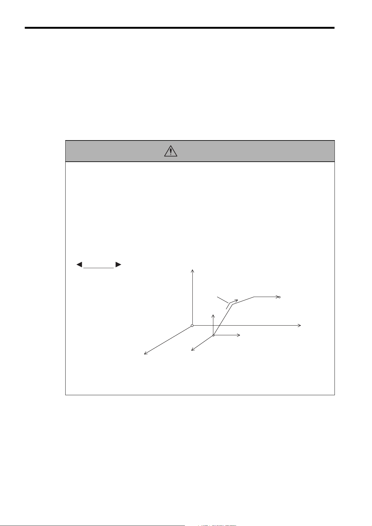
• When programming the following axis move commands, check the path to make sure that there are no
tools or other obstacles in the way of the workpiece.
The axis move commands that must be checked are as follows:
• Positioning (MOV)
• Linear Interpolation (MVS)
• Circular Interpolation (MCC, MCW)
• Helical Interpolation (MCC, MCW)
• Set Time Positioning (MVT)
• Linear Interpolation with Skip Function (SKP)
• Zero Point Return (ZRN)
• External Positioning (EXM)
axis 3
Each axis is moved
independently at rapid
traverse speed.
axis 3
Current position
axis 2
Failure to carry out the above checks may result in damage to equipment, serious personal injury,
or even death.
axis 2
Example of Basic Path for Positioning (MOV)
Positioning
axis 1
End position
axis 1
vi
Page 7
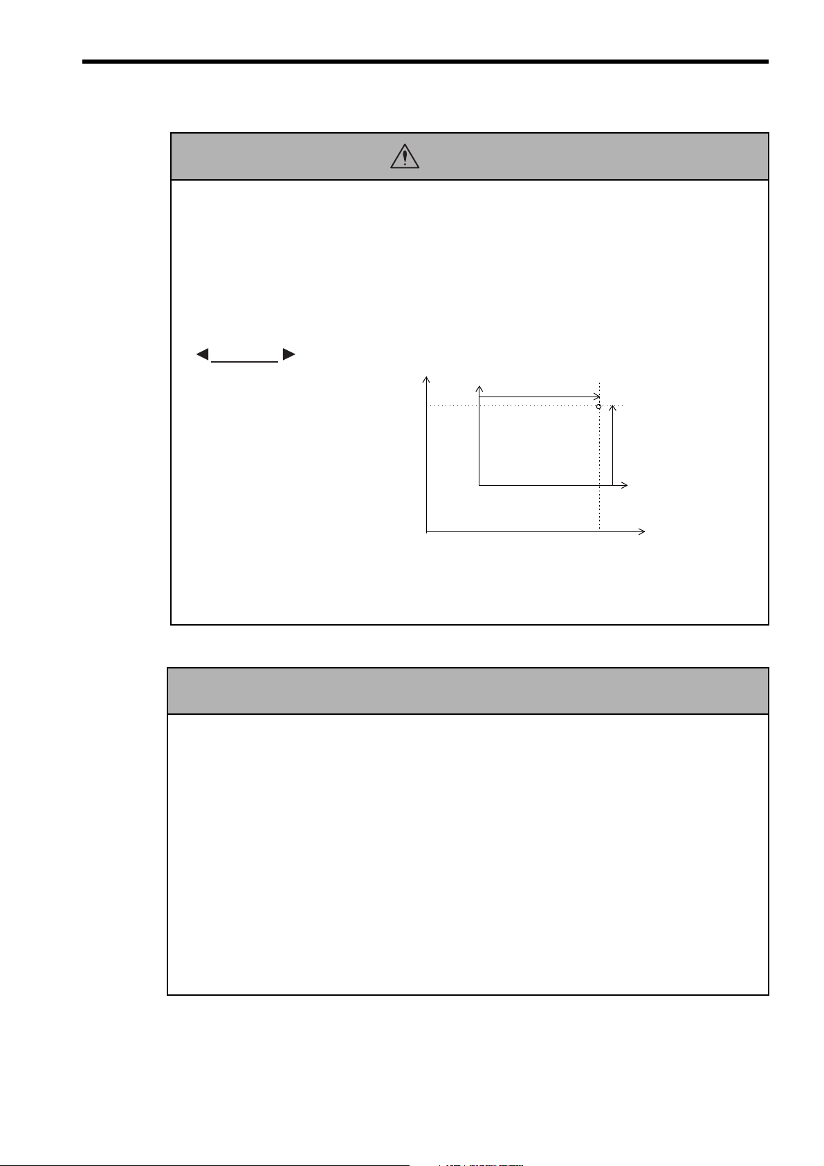
• If the following coordinate commands are designated incorrectly, the subsequent move operations will
CAUTION
be entirely different than those expected. Before starting operations, be sure to check that the settings
are designated correctly.
The coordinate commands that must be checked are as follows:
• Absolute Programming Mode (ABS)
• Incremental Programming Mode (INC)
• Current Position Set (POS)
• Move ON Machine Coordinates (MVM)
EXAMPLE
axis 2
axis 2
(axis 1)
Current position
(axis 2)
Failure to carry out the above checks may result in damage to equipment, serious personal injury, or even death.
General Precautions
• MP2000-series Machine Controller was not designed or manufactured for use in devices or systems directly
related to human life. Users who intend to use the product described in this manual for special purposes such as
devices or systems relating to transportation, medical, space aviation, atomic power control, or underwater use
must contact Yaskawa Electric Corporation beforehand.
• MP2000-series Machine Controller has been manufactured under strict quality control guidelines.
However, if this product is to be installed in any location in which a failure of MP2000-series Machine Controller involves a life and death situation or in a facility where failure may cause a serious accident, safety devices
MUST be installed to minimize the likelihood of any accident.
• Drawings and photos in this manual show typical product examples that may differ somewhat from the product
delivered.
• We will update the data sheet number for the manual and issue revisions when changes are made. The edition
number of the revised manual appears on the back of the manual.
• Contact your Yaskawa representative and quote the data sheet number on the front page of the manual if you
need to replace a manual that was lost or destroyed.
• Contact your Yaskawa representative to order new nameplates whenever a nameplate becomes worn or damaged.
(0, 0)
(0, 0)
Example of Work Coordinate System Created with
Machine coordinate system
Workpiece coordinate system
Current Position Set (POS)
Observe the following general precautions
to ensure safe application.
axis 1
axis 1
vii
Page 8

Warranty
(1) Details of Warranty
Warranty Period
The warranty period for a product that was purchased (hereinafter called “delivered product”) is one year
from the time of delivery to the location specified by the customer or 18 months from the time of shipment
from the Yaskawa factory, whichever is sooner.
Warranty Scope
Yaskawa shall replace or repair a defective product free of charge if a defect attributable to Yaskawa occurs
during the warranty period above. This warranty does not cover defects caused by the delivered product
reaching the end of its service life and replacement of parts that require replacement or that have a limited
service life.
This warranty does not cover failures that result from any of the following causes.
1. Improper handling, abuse, or use in unsuitable conditions or in environments not described in product catalogs or manuals, or in any separately agreed-upon specifications
2. Causes not attributable to the delivered product itself
3. Modifications or repairs not performed by Yaskawa
4. Abuse of the delivered product in a manner in which it was not originally intended
5. Causes that were not foreseeable with the scientific and technological understanding at the time of shipment from Yaskawa
6. Events for which Yaskawa is not responsible, such as natural or human-made disasters
(2) Limitations of Liability
1. Yaskawa shall in no event be responsible for any damage or loss of opportunity to the customer that arises
due to failure of the delivered product.
2. Yaskawa shall not be responsible for any programs (including parameter settings) or the results of program execution of the programs provided by the user or by a third party for use with programmable
Yaskawa products.
3. The information described in product catalogs or manuals is provided for the purpose of the customer purchasing the appropriate product for the intended application. The use thereof does not guarantee that there
are no infringements of intellectual property rights or other proprietary rights of Yaskawa or third parties,
nor does it construe a license.
4. Yaskawa shall not be responsible for any damage arising from infringements of intellectual property
rights or other proprietary rights of third parties as a result of using the information described in catalogs
or manuals.
viii
Page 9

(3) Suitability for Use
1. It is the customer’s responsibility to confirm conformity with any standards, codes, or regulations that
apply if the Yaskawa product is used in combination with any other products.
2. The customer must confirm that the Yaskawa product is suitable for the systems, machines, and equipment used by the customer.
3. Consult with Yaskawa to determine whether use in the following applications is acceptable. If use in the
application is acceptable, use the product with extra allowance in ratings and specifications, and provide
safety measures to minimize hazards in the event of failure.
• Outdoor use, use involving potential chemical contamination or electrical interference, or use in conditions or environments not described in product catalogs or manuals
• Nuclear energy control systems, combustion systems, railroad systems, aviation systems, vehicle systems, medical equipment, amusement machines, and installations subject to separate industry or government regulations
• Systems, machines, and equipment that may present a risk to life or property
• Systems that require a high degree of reliability, such as systems that supply gas, water, or electricity,
or systems that operate continuously 24 hours a day
• Other systems that require a similar high degree of safety
4. Never use the product for an application involving serious risk to life or property without first ensuring
that the system is designed to secure the required level of safety with risk warnings and redundancy, and
that the Yaskawa product is properly rated and installed.
5. The circuit examples and other application examples described in product catalogs and manuals are for
reference. Check the functionality and safety of the actual devices and equipment to be used before using
the product.
6. Read and understand all use prohibitions and precautions, and operate the Yaskawa product correctly to
prevent accidental harm to third parties.
(4) Specifications Change
The names, specifications, appearance, and accessories of products in product catalogs and manuals may be
changed at any time based on improvements and other reasons. The next editions of the revised catalogs or
manuals will be published with updated code numbers. Consult with your Yaskawa representative to confirm
the actual specifications before purchasing a product.
ix
Page 10

Contents
About This Manual - - - - - - - - - - - - - - - - - - - - - - - - - - - - - - - - - - - - - - - - - - - - - - - - - - - - - - iii
Using This Manual - - - - - - - - - - - - - - - - - - - - - - - - - - - - - - - - - - - - - - - - - - - - - - - - - - - - - - iii
Manuals for MP2000 Series - - - - - - - - - - - - - - - - - - - - - - - - - - - - - - - - - - - - - - - - - - - - - - - iii
Related Manuals - - - - - - - - - - - - - - - - - - - - - - - - - - - - - - - - - - - - - - - - - - - - - - - - - - - - - - - iv
Visual Aids- - - - - - - - - - - - - - - - - - - - - - - - - - - - - - - - - - - - - - - - - - - - - - - - - - - - - - - - - - - - - v
Safety Information - - - - - - - - - - - - - - - - - - - - - - - - - - - - - - - - - - - - - - - - - - - - - - - - - - - - - - - v
Safety Precautions - - - - - - - - - - - - - - - - - - - - - - - - - - - - - - - - - - - - - - - - - - - - - - - - - - - - - - vi
Warranty - - - - - - - - - - - - - - - - - - - - - - - - - - - - - - - - - - - - - - - - - - - - - - - - - - - - - - - - - - - - - viii
1 Overview
1.1 What is a Motion Program? - - - - - - - - - - - - - - - - - - - - - - - - - - - - - - - - - - - - - - 1-2
1.2 Motion Program Features - - - - - - - - - - - - - - - - - - - - - - - - - - - - - - - - - - - - - - - 1-3
1.2.1 Execution Method- - - - - - - - - - - - - - - - - - - - - - - - - - - - - - - - - - - - - - - - - - - - - - - - - - - - - - -1-3
1.2.2 Motion Control in Full Synchronization with Sequence Control - - - - - - - - - - - - - - - - - - - - - - -1-3
1.2.3 Easy to Realize High-level Motion Control- - - - - - - - - - - - - - - - - - - - - - - - - - - - - - - - - - - - - -1-4
1.2.4 Easy-to-Understand Motion Language - - - - - - - - - - - - - - - - - - - - - - - - - - - - - - - - - - - - - - - -1-4
1.2.5 Arithmetic Operations - - - - - - - - - - - - - - - - - - - - - - - - - - - - - - - - - - - - - - - - - - - - - - - - - - - -1-4
1.2.6 Data Transfer from/to Ladder Program - - - - - - - - - - - - - - - - - - - - - - - - - - - - - - - - - - - - - - - -1-5
1.2.7 Memory Usage Reduced by Use of Subprograms - - - - - - - - - - - - - - - - - - - - - - - - - - - - - - - -1-5
1.2.8 Parallel Program Execution - - - - - - - - - - - - - - - - - - - - - - - - - - - - - - - - - - - - - - - - - - - - - - - -1-6
1.2.9 Program Online Editing - - - - - - - - - - - - - - - - - - - - - - - - - - - - - - - - - - - - - - - - - - - - - - - - - - -1-6
1.2.10 Enriched Easy Programming Functions (MPE720 Ver.6.04 or later) - - - - - - - - - - - - - - - - - - -1-7
1.3 Motion Program Execution Sequence- - - - - - - - - - - - - - - - - - - - - - - - - - - - - - - 1-8
1.4 Motion Program Execution Registration - - - - - - - - - - - - - - - - - - - - - - - - - - - - - 1-9
1.5 Motion Program Execution Timing - - - - - - - - - - - - - - - - - - - - - - - - - - - - - - - - 1-10
1.6 Grouping - - - - - - - - - - - - - - - - - - - - - - - - - - - - - - - - - - - - - - - - - - - - - - - - - - 1-11
1.7 Application Examples - - - - - - - - - - - - - - - - - - - - - - - - - - - - - - - - - - - - - - - - - 1-12
1.7.1 Example 1: Handling System- - - - - - - - - - - - - - - - - - - - - - - - - - - - - - - - - - - - - - - - - - - - - -1-12
1.7.2 Example 2: Mechanical Parts Inserting Machine - - - - - - - - - - - - - - - - - - - - - - - - - - - - - - - -1-12
1.7.3 Example 3: Panel Processing Machine - - - - - - - - - - - - - - - - - - - - - - - - - - - - - - - - - - - - - - -1-13
1.7.4 Example 4: Metal Sheet Bending Equipment- - - - - - - - - - - - - - - - - - - - - - - - - - - - - - - - - - -1-13
1.8 What is a Sequence Program? - - - - - - - - - - - - - - - - - - - - - - - - - - - - - - - - - - 1-14
1.9 Sequence Program Features- - - - - - - - - - - - - - - - - - - - - - - - - - - - - - - - - - - - 1-15
1.9.1 Execution Method- - - - - - - - - - - - - - - - - - - - - - - - - - - - - - - - - - - - - - - - - - - - - - - - - - - - - -1-15
1.9.2 Programming Language Commonly Used in Motion Programs - - - - - - - - - - - - - - - - - - - - - - 1-15
1.9.3 Data Transfer from/to Motion Program - - - - - - - - - - - - - - - - - - - - - - - - - - - - - - - - - - - - - - -1-15
1.9.4 Memory Usage Reduced by Use of Subprograms - - - - - - - - - - - - - - - - - - - - - - - - - - - - - - -1-16
1.9.5 Easy Programming Functions (MPE720 Ver.6.04 or later) - - - - - - - - - - - - - - - - - - - - - - - - -1-16
x
Page 11

2 Specifications
2.1 MP2000 Series Machine Controller Specifications - - - - - - - - - - - - - - - - - - - - - - 2-2
2.1.1 Applicable Machine Controller Models- - - - - - - - - - - - - - - - - - - - - - - - - - - - - - - - - - - - - - - - 2-2
2.1.2 Applicable Motion Modules- - - - - - - - - - - - - - - - - - - - - - - - - - - - - - - - - - - - - - - - - - - - - - - - 2-2
2.1.3 List of Machine Controller Specifications - - - - - - - - - - - - - - - - - - - - - - - - - - - - - - - - - - - - - - 2-3
2.2 Engineering Tool MPE720 Specifications - - - - - - - - - - - - - - - - - - - - - - - - - - - - 2-5
2.2.1 Applicable Version Numbers of the Engineering Tool MPE720- - - - - - - - - - - - - - - - - - - - - - - 2-5
2.2.2 List of Engineering Tool MPE720 Specifications - - - - - - - - - - - - - - - - - - - - - - - - - - - - - - - - - 2-5
2.3 List of Motion Language Commands - - - - - - - - - - - - - - - - - - - - - - - - - - - - - - - 2-6
3 Program Development Flow
3.1 Program Development Flow - - - - - - - - - - - - - - - - - - - - - - - - - - - - - - - - - - - - - 3-2
3.2 Program Development Procedure - - - - - - - - - - - - - - - - - - - - - - - - - - - - - - - - - 3-3
3.2.1 Hardware Configuration - - - - - - - - - - - - - - - - - - - - - - - - - - - - - - - - - - - - - - - - - - - - - - - - - - 3-3
3.2.2 Installing MPE720 Version 6- - - - - - - - - - - - - - - - - - - - - - - - - - - - - - - - - - - - - - - - - - - - - - - 3-3
3.2.3 Communication Settings - - - - - - - - - - - - - - - - - - - - - - - - - - - - - - - - - - - - - - - - - - - - - - - - - 3-3
3.2.4 System Setup - - - - - - - - - - - - - - - - - - - - - - - - - - - - - - - - - - - - - - - - - - - - - - - - - - - - - - - - - 3-3
3.2.5 Creating Project Files - - - - - - - - - - - - - - - - - - - - - - - - - - - - - - - - - - - - - - - - - - - - - - - - - - - 3-4
3.2.6 Group Definitions - - - - - - - - - - - - - - - - - - - - - - - - - - - - - - - - - - - - - - - - - - - - - - - - - - - - - - 3-5
3.2.7 Creating a Motion Program - - - - - - - - - - - - - - - - - - - - - - - - - - - - - - - - - - - - - - - - - - - - - - - 3-6
3.2.8 Registering the Program Execution - - - - - - - - - - - - - - - - - - - - - - - - - - - - - - - - - - - - - - - - - - 3-7
3.2.9 Transferring the Motion Program- - - - - - - - - - - - - - - - - - - - - - - - - - - - - - - - - - - - - - - - - - - 3-10
3.2.10 Debugging the Program - - - - - - - - - - - - - - - - - - - - - - - - - - - - - - - - - - - - - - - - - - - - - - - - 3-12
3.2.11 Saving the Programs in Flash Memory- - - - - - - - - - - - - - - - - - - - - - - - - - - - - - - - - - - - - - 3-13
3.2.12 Executing the Programs - - - - - - - - - - - - - - - - - - - - - - - - - - - - - - - - - - - - - - - - - - - - - - - - 3-14
4 Motion Programs
4.1 Types of Motion Programs- - - - - - - - - - - - - - - - - - - - - - - - - - - - - - - - - - - - - - - 4-2
4.2 Motion Programs For Each Axis Group- - - - - - - - - - - - - - - - - - - - - - - - - - - - - - 4-2
4.3 Running a Motion Program - - - - - - - - - - - - - - - - - - - - - - - - - - - - - - - - - - - - - - 4-3
4.3.1 How to Run a Motion Program - - - - - - - - - - - - - - - - - - - - - - - - - - - - - - - - - - - - - - - - - - - - - 4-3
4.3.2 Registering the Program Execution - - - - - - - - - - - - - - - - - - - - - - - - - - - - - - - - - - - - - - - - - - 4-5
4.3.3 Work Registers - - - - - - - - - - - - - - - - - - - - - - - - - - - - - - - - - - - - - - - - - - - - - - - - - - - - - - - - 4-6
4.4 Advanced Programming - - - - - - - - - - - - - - - - - - - - - - - - - - - - - - - - - - - - - - - 4-11
4.4.1 Indirect Designation of a Program Number Using a Register - - - - - - - - - - - - - - - - - - - - - - - 4-11
4.4.2 Controlling the Motion Program Directly from an External Device- - - - - - - - - - - - - - - - - - - - 4-12
4.4.3 Monitor the Motion Program Execution Information Using S Register - - - - - - - - - - - - - - - - - 4-13
xi
Page 12

5 Sequence Programs
5.1 Sequence Program Types - - - - - - - - - - - - - - - - - - - - - - - - - - - - - - - - - - - - - - - 5-2
5.2 How to Run a Sequence Program - - - - - - - - - - - - - - - - - - - - - - - - - - - - - - - - - 5-3
5.2.1 How to Run a Sequence Program - - - - - - - - - - - - - - - - - - - - - - - - - - - - - - - - - - - - - - - - - - -5-3
5.2.2 Registering Program Execution - - - - - - - - - - - - - - - - - - - - - - - - - - - - - - - - - - - - - - - - - - - - -5-4
5.2.3 Work Register - - - - - - - - - - - - - - - - - - - - - - - - - - - - - - - - - - - - - - - - - - - - - - - - - - - - - - - - -5-5
6 Variables (Registers)
6.1 Overview - - - - - - - - - - - - - - - - - - - - - - - - - - - - - - - - - - - - - - - - - - - - - - - - - - - 6-2
6.1.1 Variable Types - - - - - - - - - - - - - - - - - - - - - - - - - - - - - - - - - - - - - - - - - - - - - - - - - - - - - - - - -6-2
6.1.2 Global Variables and Local Variables - - - - - - - - - - - - - - - - - - - - - - - - - - - - - - - - - - - - - - - - -6-4
6.2 Using Variables - - - - - - - - - - - - - - - - - - - - - - - - - - - - - - - - - - - - - - - - - - - - - - 6-7
6.2.1 System Variables (S Registers) - - - - - - - - - - - - - - - - - - - - - - - - - - - - - - - - - - - - - - - - - - - - -6-7
6.2.2 Data Variables (M Registers) - - - - - - - - - - - - - - - - - - - - - - - - - - - - - - - - - - - - - - - - - - - - - - -6-8
6.2.3 Input Variables (I Registers)- - - - - - - - - - - - - - - - - - - - - - - - - - - - - - - - - - - - - - - - - - - - - - - -6-9
6.2.4 Output Variables (O Registers) - - - - - - - - - - - - - - - - - - - - - - - - - - - - - - - - - - - - - - - - - - - - 6-11
6.2.5 C Variables (C Registers) - - - - - - - - - - - - - - - - - - - - - - - - - - - - - - - - - - - - - - - - - - - - - - - -6-13
6.2.6 D Variables (D Registers) - - - - - - - - - - - - - - - - - - - - - - - - - - - - - - - - - - - - - - - - - - - - - - - -6-14
6.3 How to Use Subscripts i, j - - - - - - - - - - - - - - - - - - - - - - - - - - - - - - - - - - - - - - 6-15
7 Programming
7.1 Motion Program Format - - - - - - - - - - - - - - - - - - - - - - - - - - - - - - - - - - - - - - - - 7-2
7.1.1 Motion Program Structure - - - - - - - - - - - - - - - - - - - - - - - - - - - - - - - - - - - - - - - - - - - - - - - - -7-2
7.1.2 Block Format - - - - - - - - - - - - - - - - - - - - - - - - - - - - - - - - - - - - - - - - - - - - - - - - - - - - - - - - - -7-2
7.1.3 Using Constants and Variables - - - - - - - - - - - - - - - - - - - - - - - - - - - - - - - - - - - - - - - - - - - - -7-7
7.2 Motion Module Parameters - - - - - - - - - - - - - - - - - - - - - - - - - - - - - - - - - - - - - - 7-9
7.2.1 Axis Type Selection - - - - - - - - - - - - - - - - - - - - - - - - - - - - - - - - - - - - - - - - - - - - - - - - - - - - -7-9
7.2.2 Reference Unit - - - - - - - - - - - - - - - - - - - - - - - - - - - - - - - - - - - - - - - - - - - - - - - - - - - - - - - - -7-9
7.2.3 Electronic Gear - - - - - - - - - - - - - - - - - - - - - - - - - - - - - - - - - - - - - - - - - - - - - - - - - - - - - - -7-10
7.2.4 Speed Reference - - - - - - - - - - - - - - - - - - - - - - - - - - - - - - - - - - - - - - - - - - - - - - - - - - - - - -7-12
7.2.5 Acceleration/Deceleration Setting- - - - - - - - - - - - - - - - - - - - - - - - - - - - - - - - - - - - - - - - - - -7-12
7.3 Group Definition - - - - - - - - - - - - - - - - - - - - - - - - - - - - - - - - - - - - - - - - - - - - - 7-13
7.4 Priority Levels of Operations - - - - - - - - - - - - - - - - - - - - - - - - - - - - - - - - - - - - 7-15
7.5 Commands and Execution Scans - - - - - - - - - - - - - - - - - - - - - - - - - - - - - - - - 7-17
7.5.1 Command Types - - - - - - - - - - - - - - - - - - - - - - - - - - - - - - - - - - - - - - - - - - - - - - - - - - - - - -7-17
7.5.2 List of Command Types- - - - - - - - - - - - - - - - - - - - - - - - - - - - - - - - - - - - - - - - - - - - - - - - - -7-18
xii
7.6 Sequence Program Format - - - - - - - - - - - - - - - - - - - - - - - - - - - - - - - - - - - - - 7-19
Page 13

8 Command Reference
8.1 Axis Setting Commands - - - - - - - - - - - - - - - - - - - - - - - - - - - - - - - - - - - - - - - - 8-3
8.1.1 Absolute Mode (ABS) - - - - - - - - - - - - - - - - - - - - - - - - - - - - - - - - - - - - - - - - - - - - - - - - - - - 8-3
8.1.2 Incremental Mode (INC)- - - - - - - - - - - - - - - - - - - - - - - - - - - - - - - - - - - - - - - - - - - - - - - - - - 8-7
8.1.3 Acceleration Time Change (ACC) - - - - - - - - - - - - - - - - - - - - - - - - - - - - - - - - - - - - - - - - - - 8-11
8.1.4 Deceleration Time Change (DCC)- - - - - - - - - - - - - - - - - - - - - - - - - - - - - - - - - - - - - - - - - - 8-17
8.1.5 S-curve Time Constant Change (SCC) - - - - - - - - - - - - - - - - - - - - - - - - - - - - - - - - - - - - - - 8-23
8.1.6 Set Velocity (VEL) - - - - - - - - - - - - - - - - - - - - - - - - - - - - - - - - - - - - - - - - - - - - - - - - - - - - - 8-29
8.1.7 Maximum Interpolation Feed Speed Setting (FMX)- - - - - - - - - - - - - - - - - - - - - - - - - - - - - - 8-35
8.1.8 Interpolation Feed Speed Ratio Setting (IFP) - - - - - - - - - - - - - - - - - - - - - - - - - - - - - - - - - - 8-37
8.1.9 Interpolation Acceleration Time Change (IAC) - - - - - - - - - - - - - - - - - - - - - - - - - - - - - - - - - 8-40
8.1.10 Interpolation Deceleration Time Change (IDC) - - - - - - - - - - - - - - - - - - - - - - - - - - - - - - - - 8-43
8.2 Axis Move Commands - - - - - - - - - - - - - - - - - - - - - - - - - - - - - - - - - - - - - - - - 8-46
8.2.1 Positioning (MOV) - - - - - - - - - - - - - - - - - - - - - - - - - - - - - - - - - - - - - - - - - - - - - - - - - - - - - 8-46
8.2.2 Linear Interpolation (MVS) - - - - - - - - - - - - - - - - - - - - - - - - - - - - - - - - - - - - - - - - - - - - - - - 8-50
8.2.3 Clockwise/Counterclockwise Circular Interpolation with Center Position Designation
(MCW, MCC) - - - - - - - - - - - - - - - - - - - - - - - - - - - - - - - - - - - - - - - - - - - - - - - - - - - - - - - - 8-55
8.2.4 Clockwise/Counterclockwise Circular Interpolation with Radius Designation (MCW, MCC) - - 8-61
8.2.5 Clockwise/Counterclockwise Helical Interpolation with Center Position Designation
(MCW, MCC) - - - - - - - - - - - - - - - - - - - - - - - - - - - - - - - - - - - - - - - - - - - - - - - - - - - - - - - - 8-65
8.2.6 Clockwise/Counterclockwise Helical Interpolation with Radius Designation (MCW, MCC) - - 8-68
8.2.7 Zero Point Return (ZRN) - - - - - - - - - - - - - - - - - - - - - - - - - - - - - - - - - - - - - - - - - - - - - - - - 8-70
8.2.8 Linear Interpolation with Skip Function (SKP)- - - - - - - - - - - - - - - - - - - - - - - - - - - - - - - - - - 8-72
8.2.9 Set Time Positioning (MVT) - - - - - - - - - - - - - - - - - - - - - - - - - - - - - - - - - - - - - - - - - - - - - - 8-74
8.2.10 External Positioning (EXM)- - - - - - - - - - - - - - - - - - - - - - - - - - - - - - - - - - - - - - - - - - - - - - 8-76
8.3 Axis Control Commands - - - - - - - - - - - - - - - - - - - - - - - - - - - - - - - - - - - - - - - 8-78
8.3.1 Current Position Set (POS) - - - - - - - - - - - - - - - - - - - - - - - - - - - - - - - - - - - - - - - - - - - - - - 8-78
8.3.2 Move On Machine Coordinates (MVM) - - - - - - - - - - - - - - - - - - - - - - - - - - - - - - - - - - - - - - 8-80
8.3.3 Program Current Position Update (PLD) - - - - - - - - - - - - - - - - - - - - - - - - - - - - - - - - - - - - - 8-81
8.3.4 In-Position Check (PFN) - - - - - - - - - - - - - - - - - - - - - - - - - - - - - - - - - - - - - - - - - - - - - - - - 8-82
8.3.5 Set In-Position Range (INP) - - - - - - - - - - - - - - - - - - - - - - - - - - - - - - - - - - - - - - - - - - - - - - 8-84
8.3.6 Coordinate Plane Setting (PLN) - - - - - - - - - - - - - - - - - - - - - - - - - - - - - - - - - - - - - - - - - - - 8-86
8.4 Program Control Commands - - - - - - - - - - - - - - - - - - - - - - - - - - - - - - - - - - - - 8-87
8.4.1 Branching Commands (IF ELSE IEND) - - - - - - - - - - - - - - - - - - - - - - - - - - - - - - - - - - - - - - 8-87
8.4.2 Repeat (WHILE WEND) - - - - - - - - - - - - - - - - - - - - - - - - - - - - - - - - - - - - - - - - - - - - - - - - 8-89
8.4.3 Parallel Execution (PFORK, JOINTO, PJOINT) - - - - - - - - - - - - - - - - - - - - - - - - - - - - - - - - 8-92
8.4.4 Selective Execution (SFORK, JOINTO, SJOINT) - - - - - - - - - - - - - - - - - - - - - - - - - - - - - - - 8-95
8.4.5 Motion Subprogram Call (MSEE) - - - - - - - - - - - - - - - - - - - - - - - - - - - - - - - - - - - - - - - - - - 8-99
8.4.6 Sequence Subprogram Call (SSEE) - - - - - - - - - - - - - - - - - - - - - - - - - - - - - - - - - - - - - - - 8-100
8.4.7 User Function Call From Motion Program (UFC) - - - - - - - - - - - - - - - - - - - - - - - - - - - - - - 8-101
8.4.8 User Function Call from Sequence Program (FUNC) - - - - - - - - - - - - - - - - - - - - - - - - - - - 8-109
8.4.9 Program End (END) - - - - - - - - - - - - - - - - - - - - - - - - - - - - - - - - - - - - - - - - - - - - - - - - - - -8-110
8.4.10 Subprogram End (RET) - - - - - - - - - - - - - - - - - - - - - - - - - - - - - - - - - - - - - - - - - - - - - - - -8-111
8.4.11 Dwell Time (TIM) - - - - - - - - - - - - - - - - - - - - - - - - - - - - - - - - - - - - - - - - - - - - - - - - - - - - -8-112
8.4.12 I/O Variable Wait (IOW) - - - - - - - - - - - - - - - - - - - - - - - - - - - - - - - - - - - - - - - - - - - - - - - -8-113
8.4.13 One Scan Wait (EOX) - - - - - - - - - - - - - - - - - - - - - - - - - - - - - - - - - - - - - - - - - - - - - - - - -8-115
xiii
Page 14

8.4.14 Single-block Signal Disabled (SNGD)/Single-block Signal Enabled (SNGE) - - - - - - - - - - - 8-116
8.5 Arithmetic Operations - - - - - - - - - - - - - - - - - - - - - - - - - - - - - - - - - - - - - - - - 8-117
8.5.1 Substitute (=) - - - - - - - - - - - - - - - - - - - - - - - - - - - - - - - - - - - - - - - - - - - - - - - - - - - - - - - - 8-117
8.5.2 Add (+) - - - - - - - - - - - - - - - - - - - - - - - - - - - - - - - - - - - - - - - - - - - - - - - - - - - - - - - - - - - 8-118
8.5.3 Subtract (-)- - - - - - - - - - - - - - - - - - - - - - - - - - - - - - - - - - - - - - - - - - - - - - - - - - - - - - - - - - 8-119
8.5.4 Multiply (*) - - - - - - - - - - - - - - - - - - - - - - - - - - - - - - - - - - - - - - - - - - - - - - - - - - - - - - - - - - 8-120
8.5.5 Divide (/) - - - - - - - - - - - - - - - - - - - - - - - - - - - - - - - - - - - - - - - - - - - - - - - - - - - - - - - - - - - 8-121
8.5.6 Remainder (MOD) - - - - - - - - - - - - - - - - - - - - - - - - - - - - - - - - - - - - - - - - - - - - - - - - - - - -8-122
8.6 Logic Operation - - - - - - - - - - - - - - - - - - - - - - - - - - - - - - - - - - - - - - - - - - - - 8-123
8.6.1 OR (|) - - - - - - - - - - - - - - - - - - - - - - - - - - - - - - - - - - - - - - - - - - - - - - - - - - - - - - - - - - - - - 8-123
8.6.2 AND (&)- - - - - - - - - - - - - - - - - - - - - - - - - - - - - - - - - - - - - - - - - - - - - - - - - - - - - - - - - - - - 8-125
8.6.3 XOR (^) - - - - - - - - - - - - - - - - - - - - - - - - - - - - - - - - - - - - - - - - - - - - - - - - - - - - - - - - - - - - 8-126
8.6.4 NOT (!) - - - - - - - - - - - - - - - - - - - - - - - - - - - - - - - - - - - - - - - - - - - - - - - - - - - - - - - - - - - - 8-127
8.7 Data Comparisons - - - - - - - - - - - - - - - - - - - - - - - - - - - - - - - - - - - - - - - - - - 8-128
8.7.1 Data Comparison Commands (==, <>, >, <, >=, <=)- - - - - - - - - - - - - - - - - - - - - - - - - - - - - 8-128
8.8 Data Operations - - - - - - - - - - - - - - - - - - - - - - - - - - - - - - - - - - - - - - - - - - - - 8-130
8.8.1 Bit Right Shift (SFR) - - - - - - - - - - - - - - - - - - - - - - - - - - - - - - - - - - - - - - - - - - - - - - - - - - -8-130
8.8.2 Bit Left Shift (SFL) - - - - - - - - - - - - - - - - - - - - - - - - - - - - - - - - - - - - - - - - - - - - - - - - - - - - 8-131
8.8.3 Block Move (BLK)- - - - - - - - - - - - - - - - - - - - - - - - - - - - - - - - - - - - - - - - - - - - - - - - - - - - -8-132
8.8.4 Clear (CLR) - - - - - - - - - - - - - - - - - - - - - - - - - - - - - - - - - - - - - - - - - - - - - - - - - - - - - - - - - 8-133
8.8.5 ASCII Conversion 1 (ASCII)- - - - - - - - - - - - - - - - - - - - - - - - - - - - - - - - - - - - - - - - - - - - - - 8-134
8.9 Basic Functions - - - - - - - - - - - - - - - - - - - - - - - - - - - - - - - - - - - - - - - - - - - - 8-136
8.9.1 Sine (SIN) - - - - - - - - - - - - - - - - - - - - - - - - - - - - - - - - - - - - - - - - - - - - - - - - - - - - - - - - - -8-136
8.9.2 Cosine (COS)- - - - - - - - - - - - - - - - - - - - - - - - - - - - - - - - - - - - - - - - - - - - - - - - - - - - - - - -8-138
8.9.3 Tangent (TAN) - - - - - - - - - - - - - - - - - - - - - - - - - - - - - - - - - - - - - - - - - - - - - - - - - - - - - - - 8-139
8.9.4 Arc Sine (ASN)- - - - - - - - - - - - - - - - - - - - - - - - - - - - - - - - - - - - - - - - - - - - - - - - - - - - - - - 8-140
8.9.5 Arc Cosine (ACS) - - - - - - - - - - - - - - - - - - - - - - - - - - - - - - - - - - - - - - - - - - - - - - - - - - - - -8-141
8.9.6 Arc Tangent (ATN) - - - - - - - - - - - - - - - - - - - - - - - - - - - - - - - - - - - - - - - - - - - - - - - - - - - -8-142
8.9.7 Square Root (SQT)- - - - - - - - - - - - - - - - - - - - - - - - - - - - - - - - - - - - - - - - - - - - - - - - - - - - 8-143
8.9.8 BCD to Binary (BIN) - - - - - - - - - - - - - - - - - - - - - - - - - - - - - - - - - - - - - - - - - - - - - - - - - - -8-145
8.9.9 Binary to BCD (BCD) - - - - - - - - - - - - - - - - - - - - - - - - - - - - - - - - - - - - - - - - - - - - - - - - - - 8-146
8.9.10 Set Bit (S{ }) - - - - - - - - - - - - - - - - - - - - - - - - - - - - - - - - - - - - - - - - - - - - - - - - - - - - - - - - 8-147
8.9.11 Reset Bit (R{ }) - - - - - - - - - - - - - - - - - - - - - - - - - - - - - - - - - - - - - - - - - - - - - - - - - - - - - - 8-148
8.9.12 Rising Pulse (PON)- - - - - - - - - - - - - - - - - - - - - - - - - - - - - - - - - - - - - - - - - - - - - - - - - - - 8-149
8.9.13 Falling Pulse (NON) - - - - - - - - - - - - - - - - - - - - - - - - - - - - - - - - - - - - - - - - - - - - - - - - - - 8-151
8.9.14 ON-Delay Timer (TON): Counting unit: 0.01 second - - - - - - - - - - - - - - - - - - - - - - - - - - - - 8-154
8.9.15 OFF-Delay Timer (TOF):Counting unit: 0.01 second- - - - - - - - - - - - - - - - - - - - - - - - - - - - 8-156
xiv
8.10 C-Language Control Commands - - - - - - - - - - - - - - - - - - - - - - - - - - - - - - - 8-158
8.10.1 C-Language Task Control (CTSK) - - - - - - - - - - - - - - - - - - - - - - - - - - - - - - - - - - - - - - - -8-158
8.10.2 C-Language Function Call (CFUNC)- - - - - - - - - - - - - - - - - - - - - - - - - - - - - - - - - - - - - - - 8-160
Page 15

9 Engineering Tool MPE720
9.1 Motion Editor - - - - - - - - - - - - - - - - - - - - - - - - - - - - - - - - - - - - - - - - - - - - - - - - 9-2
9.1.1 Overview - - - - - - - - - - - - - - - - - - - - - - - - - - - - - - - - - - - - - - - - - - - - - - - - - - - - - - - - - - - - 9-2
9.1.2 Names and Descriptions of Motion Editor Window Components - - - - - - - - - - - - - - - - - - - - - 9-4
9.2 Command Input Assistant Function - - - - - - - - - - - - - - - - - - - - - - - - - - - - - - - - 9-6
9.2.1 Overview - - - - - - - - - - - - - - - - - - - - - - - - - - - - - - - - - - - - - - - - - - - - - - - - - - - - - - - - - - - - 9-6
9.2.2 Motion Command Assist Dialog Box Details- - - - - - - - - - - - - - - - - - - - - - - - - - - - - - - - - - - - 9-8
9.3 Program Execution Registration Function - - - - - - - - - - - - - - - - - - - - - - - - - - - 9-12
9.3.1 Overview - - - - - - - - - - - - - - - - - - - - - - - - - - - - - - - - - - - - - - - - - - - - - - - - - - - - - - - - - - - 9-12
9.3.2 Program Execution Registry Screen Dialog Box Details - - - - - - - - - - - - - - - - - - - - - - - - - - 9-13
9.4 Debug Function - - - - - - - - - - - - - - - - - - - - - - - - - - - - - - - - - - - - - - - - - - - - - 9-15
9.4.1 Overview - - - - - - - - - - - - - - - - - - - - - - - - - - - - - - - - - - - - - - - - - - - - - - - - - - - - - - - - - - - 9-15
9.4.2 Motion Editor Window during Debugging - - - - - - - - - - - - - - - - - - - - - - - - - - - - - - - - - - - - - 9-16
9.5 Motion Task Manager - - - - - - - - - - - - - - - - - - - - - - - - - - - - - - - - - - - - - - - - - 9-22
9.5.1 Overview - - - - - - - - - - - - - - - - - - - - - - - - - - - - - - - - - - - - - - - - - - - - - - - - - - - - - - - - - - - 9-22
9.5.2 Motion Task Manager Window Details - - - - - - - - - - - - - - - - - - - - - - - - - - - - - - - - - - - - - - - 9-23
9.6 Drive Control Panel- - - - - - - - - - - - - - - - - - - - - - - - - - - - - - - - - - - - - - - - - - - 9-24
9.6.1 Overview - - - - - - - - - - - - - - - - - - - - - - - - - - - - - - - - - - - - - - - - - - - - - - - - - - - - - - - - - - - 9-24
9.6.2 Drive Control Panel Details- - - - - - - - - - - - - - - - - - - - - - - - - - - - - - - - - - - - - - - - - - - - - - - 9-26
9.7 Test Run Function- - - - - - - - - - - - - - - - - - - - - - - - - - - - - - - - - - - - - - - - - - - - 9-28
9.7.1 Overview - - - - - - - - - - - - - - - - - - - - - - - - - - - - - - - - - - - - - - - - - - - - - - - - - - - - - - - - - - - 9-28
9.7.2 Test Run Window Details - - - - - - - - - - - - - - - - - - - - - - - - - - - - - - - - - - - - - - - - - - - - - - - - 9-29
9.8 Axis Status and Alarm Monitor - - - - - - - - - - - - - - - - - - - - - - - - - - - - - - - - - - - 9-31
9.8.1 Overview - - - - - - - - - - - - - - - - - - - - - - - - - - - - - - - - - - - - - - - - - - - - - - - - - - - - - - - - - - - 9-31
9.8.2 Monitor Window Details - - - - - - - - - - - - - - - - - - - - - - - - - - - - - - - - - - - - - - - - - - - - - - - - - 9-33
10 Troubleshooting
10.1 Troubleshooting - - - - - - - - - - - - - - - - - - - - - - - - - - - - - - - - - - - - - - - - - - - - 10-2
10.1.1 Basic Flow of Troubleshooting - - - - - - - - - - - - - - - - - - - - - - - - - - - - - - - - - - - - - - - - - - - 10-2
10.2 Troubleshooting for Motion Programs - - - - - - - - - - - - - - - - - - - - - - - - - - - - - 10-3
10.2.1 Error Investigation Flow - - - - - - - - - - - - - - - - - - - - - - - - - - - - - - - - - - - - - - - - - - - - - - - - 10-3
10.2.2 Problem Starting a Motion Program- - - - - - - - - - - - - - - - - - - - - - - - - - - - - - - - - - - - - - - - 10-4
10.2.3 Confirming the Alarm Code - - - - - - - - - - - - - - - - - - - - - - - - - - - - - - - - - - - - - - - - - - - - - 10-9
10.2.4 Motion Program Alarm Codes- - - - - - - - - - - - - - - - - - - - - - - - - - - - - - - - - - - - - - - - - - - 10-15
10.3 Troubleshooting for Sequence Programs - - - - - - - - - - - - - - - - - - - - - - - - - 10-17
10.3.1 Error Investigation Flow - - - - - - - - - - - - - - - - - - - - - - - - - - - - - - - - - - - - - - - - - - - - - - - 10-17
10.3.2 Problem Starting a Sequence Program - - - - - - - - - - - - - - - - - - - - - - - - - - - - - - - - - - - - 10-18
xv
Page 16

Appendices
A Motion Language Commands - - - - - - - - - - - - - - - - - - - - - - - - - - - - - - - - - - - - - A-2
A.1 Axis Setting Commands - - - - - - - - - - - - - - - - - - - - - - - - - - - - - - - - - - - - - - - - - - - - - - - - - - A-2
A.2 Axis Move Commands- - - - - - - - - - - - - - - - - - - - - - - - - - - - - - - - - - - - - - - - - - - - - - - - - - - - A-3
A.3 Control Commands - - - - - - - - - - - - - - - - - - - - - - - - - - - - - - - - - - - - - - - - - - - - - - - - - - - - - - A-5
A.4 Program Control Commands - - - - - - - - - - - - - - - - - - - - - - - - - - - - - - - - - - - - - - - - - - - - - - - A-6
A.5 Arithmetic Operations - - - - - - - - - - - - - - - - - - - - - - - - - - - - - - - - - - - - - - - - - - - - - - - - - - - - A-8
A.6 Logical Operations - - - - - - - - - - - - - - - - - - - - - - - - - - - - - - - - - - - - - - - - - - - - - - - - - - - - - - A-8
A.7 Data Comparison - - - - - - - - - - - - - - - - - - - - - - - - - - - - - - - - - - - - - - - - - - - - - - - - - - - - - - - A-9
A.8 Data Operations - - - - - - - - - - - - - - - - - - - - - - - - - - - - - - - - - - - - - - - - - - - - - - - - - - - - - - - - A-9
A.9 Basic Functions - - - - - - - - - - - - - - - - - - - - - - - - - - - - - - - - - - - - - - - - - - - - - - - - - - - - - - - -A-10
A.10 C-Language Control Commands - - - - - - - - - - - - - - - - - - - - - - - - - - - - - - - - - - - - - - - - - - -A-11
B Sample Programs - - - - - - - - - - - - - - - - - - - - - - - - - - - - - - - - - - - - - - - - - - - - - A-12
B.1 Programs for Controlling Motion Program Execution - - - - - - - - - - - - - - - - - - - - - - - - - - - - - -A-13
B.2 Parallel Processing - - - - - - - - - - - - - - - - - - - - - - - - - - - - - - - - - - - - - - - - - - - - - - - - - - - - - -A-15
B.3 Motion Program for Speed Control - - - - - - - - - - - - - - - - - - - - - - - - - - - - - - - - - - - - - - - - - - -A-16
B.4 Simple Synchronized Operation Using a Virtual Axis - - - - - - - - - - - - - - - - - - - - - - - - - - - - - -A-17
B.5 Sequence Programs - - - - - - - - - - - - - - - - - - - - - - - - - - - - - - - - - - - - - - - - - - - - - - - - - - - - -A-19
C Differences between MP900 Series and MP2000 Series
Machine Controllers - - - - - - - - - - - - - - - - - - - - - - - - - - - - - - - - - - - - - - - A-21
C.1 Motion Programs - - - - - - - - - - - - - - - - - - - - - - - - - - - - - - - - - - - - - - - - - - - - - - - - - - - - - - -A-21
C.2 Sequence Programs - - - - - - - - - - - - - - - - - - - - - - - - - - - - - - - - - - - - - - - - - - - - - - - - - - - - -A-21
C.3 Motion Programming Commands - - - - - - - - - - - - - - - - - - - - - - - - - - - - - - - - - - - - - - - - - - - -A-22
C.4 Group Definitions - - - - - - - - - - - - - - - - - - - - - - - - - - - - - - - - - - - - - - - - - - - - - - - - - - - - - - -A-22
C.5 Debug Function - - - - - - - - - - - - - - - - - - - - - - - - - - - - - - - - - - - - - - - - - - - - - - - - - - - - - - - -A-23
C.6 Motion Program Alarms- - - - - - - - - - - - - - - - - - - - - - - - - - - - - - - - - - - - - - - - - - - - - - - - - - -A-23
D Precautions - - - - - - - - - - - - - - - - - - - - - - - - - - - - - - - - - - - - - - - - - - - - - - - - - A-24
D.1 General Precautions - - - - - - - - - - - - - - - - - - - - - - - - - - - - - - - - - - - - - - - - - - - - - - - - - - - - -A-24
D.2 Precautions on Motion Parameter Settings - - - - - - - - - - - - - - - - - - - - - - - - - - - - - - - - - - - - -A-24
Index
Revision History
xvi
Page 17

1
Overview
1
Overview
This chapter introduces motion programs and describes their features for those who are
unfamilier with them.
1.1 What is a Motion Program? - - - - - - - - - - - - - - - - - - - - - - - - - - - - - - - - - - 1-2
1.2 Motion Program Features - - - - - - - - - - - - - - - - - - - - - - - - - - - - - - - - - - - 1-3
1.2.1 Execution Method - - - - - - - - - - - - - - - - - - - - - - - - - - - - - - - - - - - - - - - - - - - - - - - - - 1-3
1.2.2 Motion Control in Full Synchronization with Sequence Control - - - - - - - - - - - - - - - - - - 1-3
1.2.3 Easy to Realize High-level Motion Control - - - - - - - - - - - - - - - - - - - - - - - - - - - - - - - - 1-4
1.2.4 Easy-to-Understand Motion Language - - - - - - - - - - - - - - - - - - - - - - - - - - - - - - - - - - - 1-4
1.2.5 Arithmetic Operations - - - - - - - - - - - - - - - - - - - - - - - - - - - - - - - - - - - - - - - - - - - - - - 1-4
1.2.6 Data Transfer from/to Ladder Program - - - - - - - - - - - - - - - - - - - - - - - - - - - - - - - - - - 1-5
1.2.7 Memory Usage Reduced by Use of Subprograms - - - - - - - - - - - - - - - - - - - - - - - - - - 1-5
1.2.8 Parallel Program Execution - - - - - - - - - - - - - - - - - - - - - - - - - - - - - - - - - - - - - - - - - - 1-6
1.2.9 Program Online Editing - - - - - - - - - - - - - - - - - - - - - - - - - - - - - - - - - - - - - - - - - - - - - 1-6
1.2.10 Enriched Easy Programming Functions (MPE720 Ver.6.04 or later) - - - - - - - - - - - - - 1-7
1.3 Motion Program Execution Sequence - - - - - - - - - - - - - - - - - - - - - - - - - - - 1-8
1.4 Motion Program Execution Registration - - - - - - - - - - - - - - - - - - - - - - - - - 1-9
1.5 Motion Program Execution Timing - - - - - - - - - - - - - - - - - - - - - - - - - - - - 1-10
1.6 Grouping - - - - - - - - - - - - - - - - - - - - - - - - - - - - - - - - - - - - - - - - - - - - - - 1-11
1.7 Application Examples - - - - - - - - - - - - - - - - - - - - - - - - - - - - - - - - - - - - - 1-12
1.7.1 Example 1: Handling System - - - - - - - - - - - - - - - - - - - - - - - - - - - - - - - - - - - - - - - - 1-12
1.7.2 Example 2: Mechanical Parts Inserting Machine - - - - - - - - - - - - - - - - - - - - - - - - - - - 1-12
1.7.3 Example 3: Panel Processing Machine - - - - - - - - - - - - - - - - - - - - - - - - - - - - - - - - - 1-13
1.7.4 Example 4: Metal Sheet Bending Equipment - - - - - - - - - - - - - - - - - - - - - - - - - - - - - 1-13
1.8 What is a Sequence Program? - - - - - - - - - - - - - - - - - - - - - - - - - - - - - - 1-14
1.9 Sequence Program Features - - - - - - - - - - - - - - - - - - - - - - - - - - - - - - - - 1-15
1.9.1 Execution Method - - - - - - - - - - - - - - - - - - - - - - - - - - - - - - - - - - - - - - - - - - - - - - - - 1-15
1.9.2 Programming Language Commonly Used in Motion Programs - - - - - - - - - - - - - - - - 1-15
1.9.3 Data Transfer from/to Motion Program - - - - - - - - - - - - - - - - - - - - - - - - - - - - - - - - - - 1-15
1.9.4 Memory Usage Reduced by Use of Subprograms - - - - - - - - - - - - - - - - - - - - - - - - - 1-16
1.9.5 Easy Programming Functions (MPE720 Ver.6.04 or later) - - - - - - - - - - - - - - - - - - - - 1-16
1-1
Page 18

1 Overview
1.1 What is a Motion Program?
The motion program is a program written in motion language, Yaskawa’s unique textual language.
A motion program can be executed either by coding an MSEE command in a ladder program or by registering
the motion program in the program execution registry screen dialog box for the M-EXECUTOR Module.
Note: The M-EXECUTOR Module can not be used with the following modules and Machine Controllers:
MP2300, CPU-01, CPU-02
Apart from ladder programs, up to 256 motion programs can be created.
An example of a motion program is shown below.
The features of motion programs are described starting from the next page.
1-2
Page 19

1
Overview
1.2 Motion Program Features
Ladder program
(Scan execution)
Motion program
(Sequential execution)
One program
is executed
in a fixed
cycle.
IB00000 IB00001 OB00000
IB00002
IB00003
DB000005
IB00004 DB000006 OB00001
END
MOV [X]1000 [Y]2000;
MOV [X]-1000 [Y]-2000;
MVS [X]2000 [Y]1000 F30000;
END;
At the completion of
execution of one
move command,
the next command will
be executed.
Sequence Control Motion Control
(Motion Module)
Ladder program (High-speed scan)
MPM001
Motion program
Starts the motion
program
VEL [X]2000 [Y]2000;
ACC [X]100 [Y]100;
DCC [X]100 [Y]100;
MOV [X]0 [Y]0;
MVS [X]100.0 [Y]200.0;
Motion control in full
synchronization with
high-speed scans
Motion parameters
Set motion
parameters
Fully
synchronized
control
Position
control
Speed
control
Torque
control
1.2.1 Execution Method
A motion program employs an execution method that differs from the ladder program.
With a ladder program, processing from the program start to an END command is completed within one scan.
With a motion program, the processing requested by one command normally requires more than one scan.
Also, the commands are executed sequentially, in the order they are coded.
In this manual, the execution method of ladder program is referred to as Scan Execution, and that of a motion
program as Sequential Execution.
1.2 Motion Program Features
1.2.2 Motion Control in Full Synchronization with Sequence Control
The process written in a motion program is executed in full synchronization with high-speed scans of the
MP2000-series Machine Controller. The axis movement will start within one scan after the start request from the
ladder program, without any time lag to start the motion program.
1-3
Page 20
1 Overview
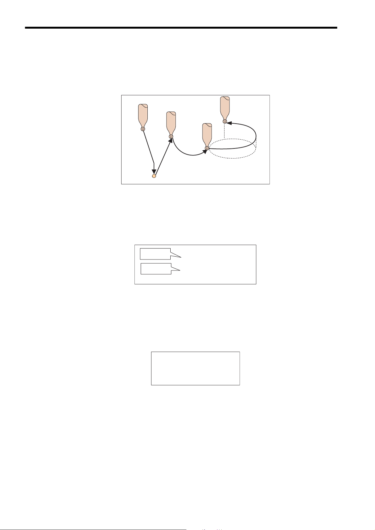
1.2.3 Easy to Realize High-level Motion Control
1.2.3 Easy to Realize High-level Motion Control
In addition to basic motion control, motion control that involves complicated movements can be easily realized
by using motion programs.
Positioning
Circular
interpolation
Linear
interpolation
Helical
interpolation
1.2.4 Easy-to-Understand Motion Language
A motion program employs intuitive motion language commands such as VEL to set a velocity and MOV for
positioning.
Set Velocity
Positioning
VEL [A1]1000 [B1]500;
MOV [A1]100 [B1]200;
1.2.5 Arithmetic Operations
The motion language includes commands for arithmetic operations and logical operations.
These commands allow you to include various calculations, such as calculation of target position in a motion program.
DL00000 = DL00002+DW00004;
DL00000 = DW00002
MW00000 = MW00000 & 00FFH;
MF00000 =
SIN(30.0);
DL00004;
*
1-4
Page 21
1
Overview
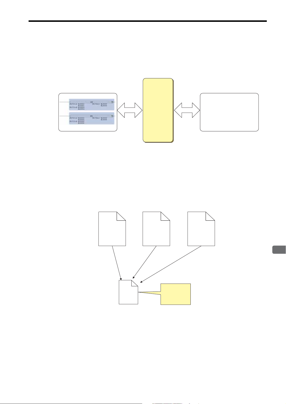
1.2.6 Data Transfer from/to Ladder Program
Data register
(M register)
MOV [A1] ML00000;
Ladder program
Motion program
Read Update
Read Update
Main program
MPM001
Main program
MPM002
Main program
MPM003
Subprogram
MPS010
Calling
(MSEE)
Write common
processing in a
subprogram.
Calling
(MSEE)
Calling
(MSEE)
Data can be transferred between a ladder program and motion program.
Data registers (M registers) are used to transfer the data.
In this way, a value updated in a ladder program can be used in a motion program, and vice versa
1.2 Motion Program Features
1.2.7 Memory Usage Reduced by Use of Subprograms
Subroutines (subprograms) can be created within a motion program.
The number of program steps can be minimized by creating a subprogram that includes a set of commands to
perform a repeated or regular task, thus reducing memory usage.
1-5
Page 22
1 Overview
MP2000series
Machine
Controller
Task 1
Task 2
Task 16
Processing 1
Subprogram
Processing
1-1
Processing
1-2
Processing 2
Processing 3
Processing 4
Task
Simultaneous
execution of
up to 16 tasks
Up to four main programs
can be executed
in parallel.
Up to two subprograms
can be executed in
parallel.
Offline editing
Online editing
Programming
Operation to transfer a program
to the Machine Controller
Debugging
INFO
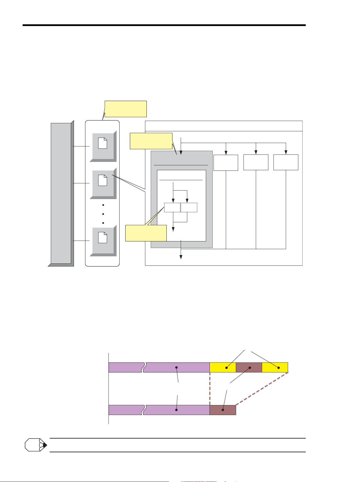
1.2.8 Parallel Program Execution
1.2.8 Parallel Program Execution
With a single MP2000-series Machine Controller, up to 16 tasks can be simultaneously executed using motion
programs. With one motion program, up to four main programs can be simultaneously executed. Additionally, up
to two subprograms can be simultaneously executed by calling subprograms from the main program. Multiple
different movements can be simultaneously controlled by using such the parallel program execution function.
1.2.9 Program Online Editing
Motion programs can be edited online in the same way as ladder programs.
Online editing refers to editing programs with the programming device logged on to the Machine Controller.
In online editing mode, the operation to save the edited program automatically transfers the saved program to the
Machine Controller. Thus, an operation to transfer to the Machine Controller is not required and program development efficiency is improved.
Online editing is disabled while a motion program is running.
1-6
Page 23

1.2 Motion Program Features
1
Overview
Test Run Function
Control the axes onscreen.
Program Execution Registration Function
Easily register programs to be executed in the system.
Operation Control Panel Function
Start motion programs from the Motion
Editor window.
Debug Function
Debug a motion program.
The debug commands, including step-by-step execution
and break point setting, are provided.
Axis Operation Monitor Function
View the motion status of each axis onscreen.
Command Input Assistant Function
Simply select a command and set data in the Motion
Command Assist dialog box to insert the command in
the editor.
Inserts the command
1.2.10 Enriched Easy Programming Functions (MPE720 Ver.6.04 or later)
The engineering tool MPE720 Ver.6 for MP2000-series Machine Controllers is provided with the following easy
programming functions.
1-7
Page 24

1 Overview
H
H01
H02
H01.01
H01.02
Ladder program
MP2000-series Machine Controller
M-EXECUTOR
Program Definition tab
Calling
Calling
Motion programs
SVR
Built-in
SVB
SVB-01
SVA-01
PO-01
Transfer the created programs
MSEE command
Motion Editor Window
Can call motion
programs without using
ladder program
Capable of storing
up to 256 programs
Motion parameters
MPE720
VEL [X]2000 [Y]2000;
ACC [X]100 [Y]100;
DCC [X]100 [Y]100;
MOV [X]0 [Y]0;
MVS [X]100.0 [Y]200.0;
ABS;
FMX T100000;
MVS [C1]300 [D1]400
F1000;
END;
MPM002
MPM001
Can call up to
16 programs at once
1.3 Motion Program Execution Sequence
The motion programs created on the MPE720 Motion Editor window are transferred to the MP2000-series
Machine Controller. The transferred motion programs can be called by MSEE commands coded in the ladder
program, or from the execution registry screen dialog box of the M-EXECUTOR Module. Motion commands are
sent to the motion module via the motion parameters to move axes.
The following diagram illustrates how motion programs created using the MPE720 are executed.
1-8
Page 25

1
Overview
1.4 Motion Program Execution Registration
INFO
M-EXECUTOR
Program definition
MPM001
INC;
VEL [A1]100 [B1]200;
MOV [A1]1000 [B1]2000;
END;
Motion program
Control registers
Calls
INFO
Execution of motion programs can be registered in two ways.
Calling a Motion Program from the Ladder Program
Code an MSEE command in an H drawing to call the motion program to run. An MSEE work register is used
to start/stop the called motion program. Motion programs can be called from any H drawing: parent drawing,
child drawing, or grandchild drawing.
DWG.H
Calls
INC;
VEL [A1]100 [B1]200;
1.4 Motion Program Execution Registration
Motion program
MPM001
Work register
Status
Control signal
Interpolation override
System work number
MOV [A1]1000 [B1]2000;
END;
In this manual, the high-speed processing drawing of a ladder program is referred to as H drawing.
Registering Motion Programs in M-EXECUTOR
Register motion programs in the M-EXECUTOR program execution definition. A control register (I/O register) is used to start or stop the registered motion program.
M-EXECUTOR is a software module to execute motion programs and sequence programs.
1-9
Page 26
1 Overview
Empty
I/O service
(Output)
H drawing
M-EXECUTOR
External device
Batch
output
Batch
input
MP2000-series CPU
Requests
to execute
Reports
Motion program
Status
Control signal
Subprogram
M-EXECUTOR
Requests
to execute
Reports
Status
Control signal
High-speed scan
High-speed scan
High-speed scan
I/O service
(Input)
Empty Empty
MSEE
END;
MPM001
RET;
MPS101
DWG.H
Motion program
Subprogram
MSEE
END;
MPM002
RET;
MPS102
System processing
Output (O)
register
Input (I)
register
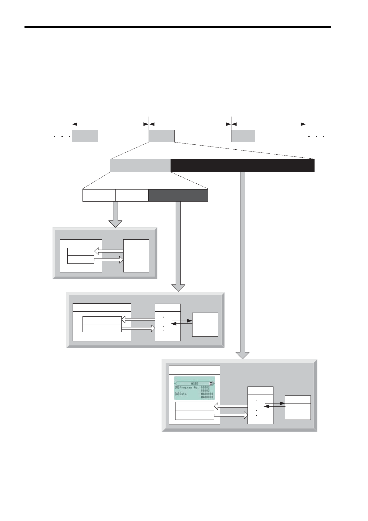
1.5 Motion Program Execution Timing
Motion programs are executed in full synchronization with MP2000 high-speed scans. In every high-speed scan
cycle, I/O services are performed first, and the motion program registered in M-EXECUTOR is executed.
Next, the motion program initiated in the MSEE command coded in the DWG.H is executed at the timing of the
MSEE command execution.
The following diagram illustrates motion program execution timing.
1-10
Page 27

1
Overview
1.6 Grouping
The axes involved in related operations are organized into individual groups. Motion programs can be created for
each group. This allows one MP2000-series Machine Controller to independently control multiple machines
using group operation. Group operation can be single group operation or multiple group operation.
Definitions for axes to be grouped together are made under Group Definitions.
Single Group Operation
1.6 Grouping
MP2000 series
Machine Controller
Multiple Group Operation
A1 B1 A2 D2 A3
SGDS
SGDS
A1 B1 C1 F1 G1
Group1
SGDS
SGDS
SGDS
MP2000 series
Machine Controller
SGDS
SGDS
G
roup1Group2Group3
SGDS
SGDS
SGDS
Groups are organized
in a tree structure.
1-11
Page 28
1 Overview
Pallet
Pallet
+
+
-
+
-
+
-
+
-
+
-
-
2
Printed
board
Stand
Parts tray
Robot 2
Robot 1
1.7.1 Example 1: Handling System
1.7 Application Examples
Motion programs can be used for operations of various systems.
Some application examples are shown below.
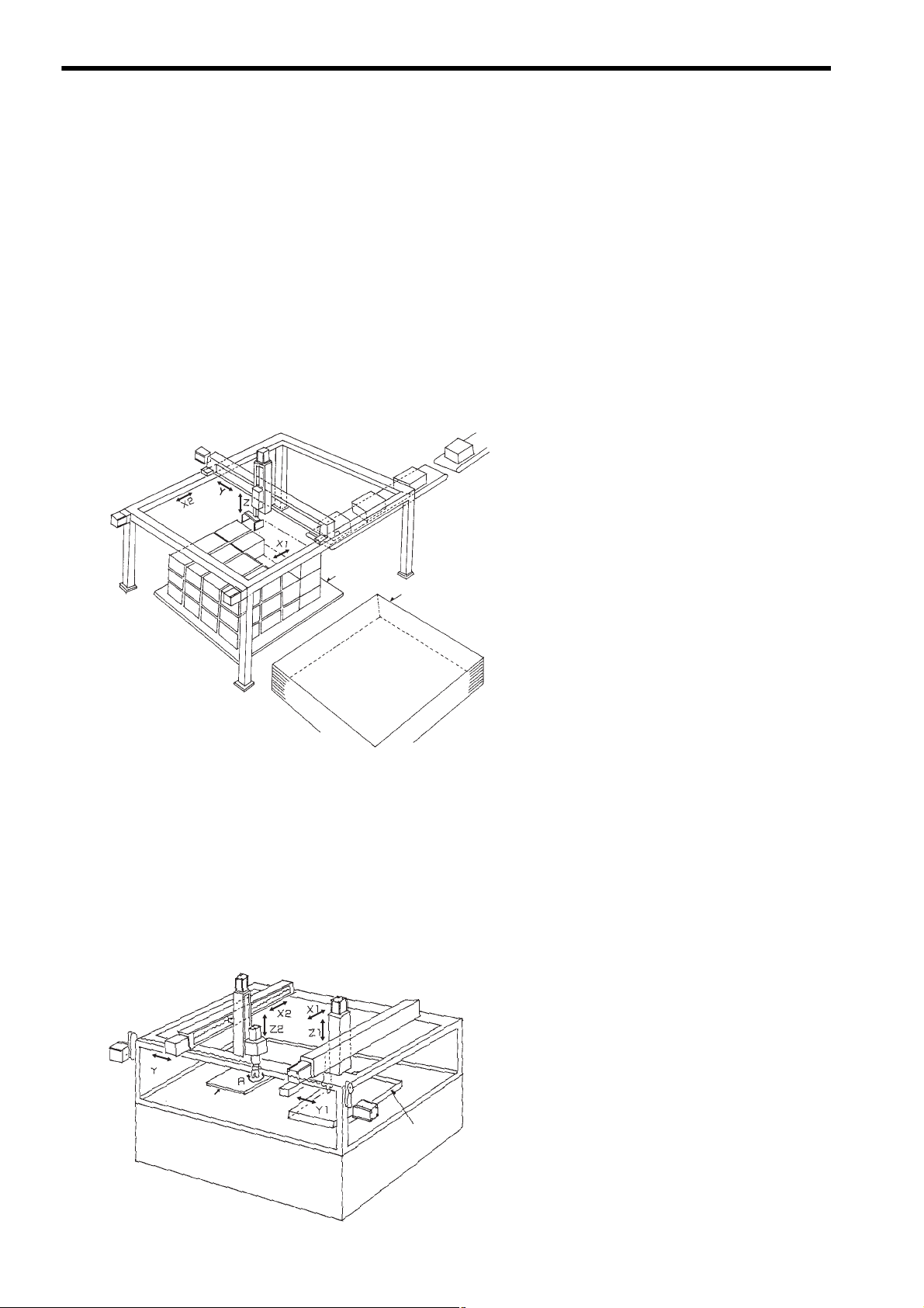
1.7.1 Example 1: Handling System
Outline
• To stack a specified number of cardboard boxes on a pallet
and transport them to the next process
• The system operation includes three axes motion control for
the palletizing process and an automatic pallet feeding
sequence.
Control points
• Moves X1 and X2 axes in synchronization using
• Realizes smooth movements by using interpola-
• Palletizes by calculating the position data with the
1.7.2 Example 2: Mechanical Parts Inserting Machine
Outline
• To insert parts, such as connectors, in a printed board.
• The handling robot takes out the parts and brings them to the
stand. The inserting robot inserts the parts in the specified position and angle on the board.
a virtual axis.
tion.
motion program according to predefined conditions (box dimensions, the number of boxes in a
horizontal row, the number of boxes in a vertical
row, and the number of boxes in a stack.
1-12
Control points
• Two groups of axes are organized, and programs
are created for each group, so that each robot is
independently controlled.
• The tact time can be shortened by using two-axes
or three-axes linear interpolation.
Page 29

1
Overview
1.7.3 Example 3: Panel Processing Machine
z
Y
Wave forms
Cutter
Flat panel
Outline
• To draw waveforms on a flat panel made of construction
material.
• More than ten cutters are mounted in series on the X axis, and
the width of the pattern can be easily changed.
1.7 Application Examples
Control points
• Moves X and Y axes in circular interpolation
to draw waveforms.
• Moves Y1 and Y2 axes in synchronization
using a vertical axis.
1.7.4 Example 4: Metal Sheet Bending Equipment
Outline
• To bend a metal sheet
• A metal sheet can be bent into various shapes by changing the
adjusting axis while feeding a sheet using the rolling axis.
Workpiece
Motor for
adjusting roller
platform
Gear
Motor for feeding roller
Feeding roller (urethane)
Adjusting roller
Workpiece
(metal sheet)
Motor for
inserting workpieces
Control points
• Controls two axes, a linear axis and rotational axis, in linear interpolation.
• Switches the motion program to be called
according to the process.
1-13
Page 30
1 Overview
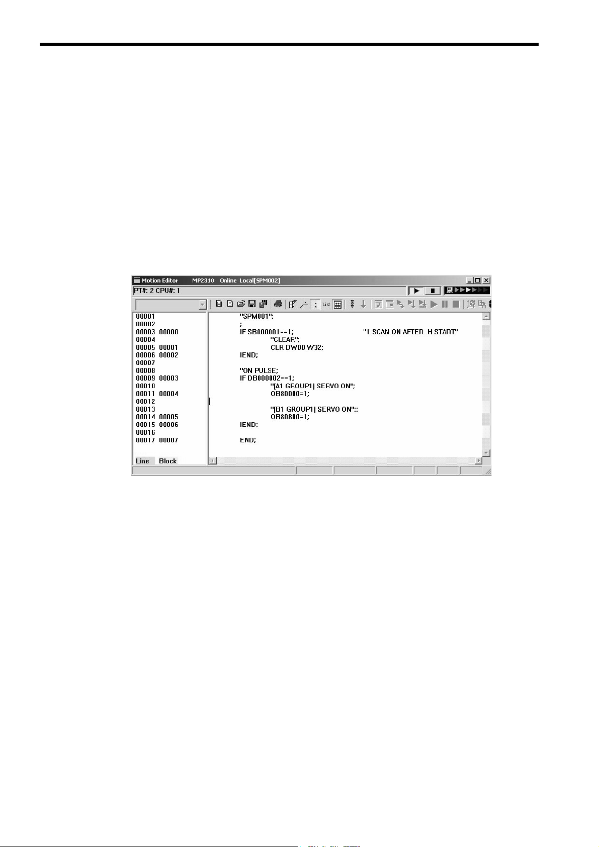
1.8 What is a Sequence Program?
The sequence program is a scan execution type program written in the language commonly used for the motion
program.
An application to cyclically check a status, such as an interlock, can be created by using a sequence program.
A sequence program can be executed by calling from the program execution registry screen dialog box of MEXECUTOR Module.
Note: The M-EXECUTOR Module can not be used with the following modules and Machine Controllers:
MP2300, CPU-01, CPU-02
A total of up to 256 sequence and motion programs can be created.
An example of a sequence program is shown below.
The features of sequence programs are described, starting from the next page.
1-14
Page 31

1
Overview
1.9 Sequence Program Features
Sequence program
(Scan execution type)
Ladder program
(Scan execution type)
Executed in
a constant
cycle
IB00000 IB00001 OB00000
IB00002
IB00003
DB000005
IB00004 DB000006 OB00001
END
OB00000 = IB00000 & IB00001;
DB000005 = IB00002 | IB00003;
OB00001 = PON(IB00004 DB000006);
END;
Executed in
a constant
cycle
Data register
(M register)
MOV [A1] ML00000;
Sequence program
Motion program
Read
Update
Read Update
ML00000
= ML00002 + ML00004;
ML00000
= ML00000 * ML00006;
END;
1.9.1 Execution Method
A sequence program employs the same execution method as the ladder program.
A sequence program is a cyclically executed scan execution type program. Processing from the program start to
an END command is completed within one scan.
Sequence programs can be used by registering them in the program execution registry screen dialog box of MEXECUTOR Module.
1.9 Sequence Program Features
1.9.2 Programming Language Commonly Used in Motion Programs
A sequence program employs the same motion language as a motion program.
The motion language commands that can be used in sequence programs, however, are limited to sequence commands, such as math commands. Commands for motion control, such as axis move commands, cannot be used.
The use of sequence programs allows you to create an application for sequence control without using a ladder
program.
1.9.3 Data Transfer from/to Motion Program
Data can be transferred between a sequence program and a motion program.
Data registers (M registers) are used to transfer the data.
In this way, data updated in the sequence program can be used in the motion program, and vice versa.
1-15
Page 32

1 Overview
Debug Function
Debug a sequence program.
The debug commands, including step-by-step execution
and break point setting, are provided.
Command Input Assistant Function
Simply select a command and set data in the Motion
Command Assist dialog box to insert the command
in the editor.
Inserts the command
1.9.4 Memory Usage Reduced by Use of Subprograms
1.9.4 Memory Usage Reduced by Use of Subprograms
Subroutines (subprograms) can be created within a sequence program.
The number of program steps can be minimized by creating a subprogram that includes a set of commands to
perform a repeated or regular task, thus reducing memory usage.
Main program
SPM001
Call
(SSEE)
SPS010
Subprogram
Main program
SPM002
Call
(SSEE)
Write a repeated
or regular task in
a subprogram
Main program
SPM003
Call
(SSEE)
1.9.5 Easy Programming Functions (MPE720 Ver.6.04 or later)
The following easy programming functions can also be used for sequence programs.
1-16
Page 33

2
Specifications
2
Specifications
This chapter describes the relevant specifications of motion program and engineering tool
MPE720.
2.1 MP2000 Series Machine Controller Specifications - - - - - - - - - - - - - - - - - -2-2
2.1.1 Applicable Machine Controller Models - - - - - - - - - - - - - - - - - - - - - - - - - - - - - - - - - - - 2-2
2.1.2 Applicable Motion Modules - - - - - - - - - - - - - - - - - - - - - - - - - - - - - - - - - - - - - - - - - - - 2-2
2.1.3 List of Machine Controller Specifications - - - - - - - - - - - - - - - - - - - - - - - - - - - - - - - - - 2-3
2.2 Engineering Tool MPE720 Specifications - - - - - - - - - - - - - - - - - - - - - - - - 2-5
2.2.1 Applicable Version Numbers of the Engineering Tool MPE720 - - - - - - - - - - - - - - - - - - 2-5
2.2.2 List of Engineering Tool MPE720 Specifications - - - - - - - - - - - - - - - - - - - - - - - - - - - - 2-5
2.3 List of Motion Language Commands - - - - - - - - - - - - - - - - - - - - - - - - - - -2-6
2-1
Page 34

2 Specifications
INFO
2.1.1 Applicable Machine Controller Models
2.1 MP2000 Series Machine Controller Specifications
2.1.1 Applicable Machine Controller Models
Motion programs can be used with the following MP2000-series Machine Controller models.
• MP2100
• MP2100M
• MP2200/CPU-01
• MP2200/CPU-02
• MP2200/CPU-03
• MP2200/CPU-04
• MP2300
• MP2300S
• MP2310
• MP2400
• MP2500
• MP2500D
• MP2500M
• MP2500MD
• MPU-01
With the exception of MP2300, CPU-01 and CPU-02, both motion programs and sequence programs can be used.
If using the M-EXECUTOR module or sequence programs with MP2100 or MP2100M, the programming tools with fol-
lowing versions are required.
MP2000 Series Controller Applicable Version MPE720 Applicable Version
MP2100
MP2100M
Ver 2.66 or later MPE720 Ver 5 MPE720 Ver 5.44 or later
2.1.2 Applicable Motion Modules
The following motion modules support motion programs.
The axes connected to the following motion modules can be controlled using motion programs.
• Built-in SVB (Built in MP2100, MP2100M, MP2300, MP2300S, MP2310, MP2400, and MP2500,
MP2500D, MP2500M, MP2500MD as a standard feature)
• SVR (Mounted on all models of MP2000-series Machine Controllers as standard)
• SVA-01
• SVB-01
• PO-01
MPE720 Ver 6 MPE720 Ver 6.10 or later
MPE720 Ver 6.10 Lite or later
2-2
Page 35

2
Specifications
2.1 MP2000 Series Machine Controller Specifications
2.1.3 List of Machine Controller Specifications
MP2200
MP2100,
MP2100M
Program Capacity 5.5 MB 7.5 MB 11.5 MB
Applicable N/A Applicable −
Start
Processing
Interrupt
Processing
High-speed
Processing
Ladder Program
Low-speed
Processing
User function 500 drawings max. −
Number of
Programs
Number of
Groups
Number of
Tasks
Number of
Parallel
Processes
(Per Task)
Execution
Method
Starting
Method
Override Can be set in the range from 0.01% to 327.67%. −
Operation
Motion Program
Mode
Reference Unit
Min.
Reference Unit
Reference
Range
Number of
Simultaneously
Controlled
Axes
(Per Task)
64 drawings max. −
64 drawings max. −
200 drawings max. −
500 drawings max. −
Applicable −
256 programs max.
Eight groups
16 tasks
Eight parallel processes
• By writing an MSEE instruction in the ladder program
• By using an M-EXECUTOR Module (Excluding MP2300, CPU-01 and CPU-02)
The program starts running at the rising edge of control signal bit 0
(Program start request).
ABS (absolute) and INC (incremental) mode
• Built-in SVB, SVB-01, and SVR Module:
pulse, mm, deg, inch, μm
• SVA-01 and PO-01 Module:
pulse, mm, deg, inch
• E pulse
1
• mm, deg, inch, μm
1, 0.1, 0.01, 0.001, 0.0001, 0.00001
-2147483648 to +2147483647 (32-bit with sign) −
16 axes max. −
MP2300 MP2300S MP2400
MP2200
/CPU-01
MP2310
MP2200
/CPU-02
/CPU-03,
MP2200
/CPU-04,
MPU-01
Remarks
Total user program
capacity including ladder programs, motion
programs, and
sequence programs.
Up to a total of 256
motion programs and
sequence program.
Up to 16 axes can be
set for one group.
Number of motion
programs that can be
executed simultaneously.
Parallel execution of
four main programs
parallel execution of
two subprograms.
−
−
Mode switching by
use of the exclusive
command (ABS/INC).
−
−
×
2-3
Page 36

2 Specifications
2.1.3 List of Machine Controller Specifications
MP2200
MP2100,
MP2100M
Applicable N/A Applicable N/A
Number of
Programs
Number of
Ta sk s
Number of
Parallel
Processings
(Per Task)
Sequence Program
Execution
Method
Start Method Started by the system.
M Register Accessible (65535 words)
S Register Accessible (8192 word)
I Register Accessible (32768 words and motion monitoring parameters) −
O Register Accessible (32768 words and motion setting parameters) −
C Register Accessible (16384 words) −
D Register Accessible (Can be specified in the range from 0 to 16384 words)
Accessible Registers
# Register
256 programs max.
(The execution timing can be selected from the start drawing, high-speed scan drawing,
or low-speed scan drawing.)
16 tasks max.
None −
By using the M-EXECUTOR Module −
Accessible only from ladder program (Can be specified in the range from 0 to 16384
words)
(# register cannot be accessed from motion program and sequence program.)
MP2300 MP2300S MP2400
MP2200
/CPU-01
MP2310
Applicable
MP2200
/CPU-02
N/A
/CPU-03,
MP2200
/CPU-04,
MPU-01
Applicable
Remarks
−
Up to a total of 256
motion programs and
sequence.
Number of sequence
programs that can be
executed simultaneously.
Started by the system
by registering programs in the MEXECUTOR module.
Memory backed up by
battery.
Memory backed up by
battery.
Internal register
unique to each drawing. Can be used by
only the corresponding drawing.
−
2-4
Page 37

2.2 Engineering Tool MPE720 Specifications
2
Specifications
INFO
2.2 Engineering Tool MPE720 Specifications
2.2.1 Applicable Version Numbers of the Engineering Tool MPE720
Motions programs and/or sequence programs can be created or edited on the following engineering tool MPE720
versions.
• MPE720 Ver.5
• MPE720 Ver.6 (Compatible with all models of MP2000-series Machine Controllers)
• MPE720 Ver.6 Lite (Compatible only with MP2400)
The above engineering tool software can be installed on one personal computer.
2.2.2 List of Engineering Tool MPE720 Specifications
(Compatible with MP2000-series Machine Controller models excluding MP2400)
MPE720 Ver.5
(CPMC-MPE720)
MP2100 Compatible Not compatible −
MP2100M Compatible Not compatible −
MP2200/CPU-01 Compatible Not compatible −
MP2200/CPU-02 Compatible Not compatible −
MP2200/CPU-03 Compatible Not compatible −
MP2200/CPU-04 Compatible Not compatible −
MP2300 Compatible Not compatible −
MP2300S Compatible Not compatible −
MP2310 Compatible Not compatible −
Machine Controller Model
MP2400 Not compatible Compatible −
MPU-01 Compatible Not compatible −
Ladder Program Supported Not supported −
Motion Program Supported −
Sequence Program Supported −
Programs
Command Input Assistant
Function
Program Execution
Registration Function
Debug Function Provided −
Motion Task Manager Provided −
Drive Control Panel
Test Run Function Not provided Provided (Ver.6.04 or later) −
Axis Operation Monitor/
Alarm Monitor Function
Not provided Provided (Ver.6.04 or later) −
Provided
(Ver.5.38 or later)
Provided
(Ver.5.38 or later)
Not provided Provided (Ver.6.04 or later) −
MPE720 Ver.6
(CPMC-MPE770)
Provided (Ver. 6.04 or later)
Provided (Ver.6.04 or later)
MPE720 Ver.6 Lite
(CPMC-MPE770L)
Remarks
Not supported by
MP2300, CPU-01,
CPU-02
Not supported by
MP2300, CPU-01,
CPU-02
2-5
Page 38

2 Specifications
2.3 List of Motion Language Commands
Type Command Name Type Commands Name
ABS Absolute Mode
INC Incremental Mode + Add
ACC Acceleration Time Change - Subtract
DCC Deceleration Time Change * Multiply
SCC S-curve Time Constant Change / Divide
VEL Set Speed MOD Remainder
FMX Maximum Interpolation Feed Speed
IFP Interpolation Feed Speed Ratio Setting & AND (Logical AND)
Axis Set Commands
Axis Move Commands
Control Commands
Program Control Commands
IAC Interpolation Acceleration Time Change ^
IDC Interpolation Deceleration Time Change ! NOT (Inversion)
MOV Positioning
MVS Linear Interpolation <> Mismatch
MCW Clockwise Circular/Helical Interpolation > Greater than
MCC
ZRN Zero Point Return >= Greater than or equal to
SKP Linear Interpolation with SKIP Function <= Less than or equal to
MVT Set Time Positioning
EXM External Positioning SFL Left Shift
POS Current Position Set BLK Block Move
MVM Move On Machine Coordinates CLR Clear
PLN Coordinate Plane Setting ASCII ASCII Conversion 1
PLD Program Current Position Update
PFN In-Position Check COS Cosine
INP Set In-Position Check Width TAN Tange nt
IF ELSE IEND Branch ASN Arc Sine
WHILE WEND Repeat ACS Arc Cosine
PFORK,
JOINTO,
PJOINT
SFORK,
JOINTO,
SJOINT
MSEE Subroutine (motion subprogram) Call PON Rising Pulse
SSEE Subroutine (sequence subprogram) Call NON Falling Pulse
UFC User Function Call from Motion Program
FUNC User Function Call from Sequence Program
END Program End
RET Subprogram End
TIM Dwell Time
IOW I/O Variable Wait
EOX One Scan Wait
SNGD/SNGE Disable/Enable Single Block
Counterclockwise Circular/Helical
Interpolation
Parallel Execution
Selective Execution
Arithmetic
Operation
Logical
Operation
Data
Comparison
Data Operation
Basic Functions
C Language
Control Commands
= Substitute
| OR (Logical OR)
XOR (Logical exclusive
OR)
== Match
< Less than
SFR Right Shift
SIN Sine
ATN Arc Tangent
SQT Square Root
BIN BCD to Binary
BCD Binary to BCD
S{ } Set Bit
R{ } Reset Bit
TON On-Delay Timer
TOF Off-Delay Timer
CTSK
CFUNC
C Language Task
Control
C Language Function
Call
2-6
Page 39

3
Program Development Flow
3
Program Development Flow
This chapter describes the procedures from system setup to operation start using the programming tool MPE720 version 6.
3.1 Program Development Flow - - - - - - - - - - - - - - - - - - - - - - - - - - - - - - - - -3-2
3.2 Program Development Procedure - - - - - - - - - - - - - - - - - - - - - - - - - - - - -3-3
3.2.1 Hardware Configuration - - - - - - - - - - - - - - - - - - - - - - - - - - - - - - - - - - - - - - - - - - - - - 3-3
3.2.2 Installing MPE720 Version 6 - - - - - - - - - - - - - - - - - - - - - - - - - - - - - - - - - - - - - - - - - - 3-3
3.2.3 Communication Settings - - - - - - - - - - - - - - - - - - - - - - - - - - - - - - - - - - - - - - - - - - - - 3-3
3.2.4 System Setup - - - - - - - - - - - - - - - - - - - - - - - - - - - - - - - - - - - - - - - - - - - - - - - - - - - - 3-3
3.2.5 Creating Project Files - - - - - - - - - - - - - - - - - - - - - - - - - - - - - - - - - - - - - - - - - - - - - - 3-4
3.2.6 Group Definitions - - - - - - - - - - - - - - - - - - - - - - - - - - - - - - - - - - - - - - - - - - - - - - - - - 3-5
3.2.7 Creating a Motion Program - - - - - - - - - - - - - - - - - - - - - - - - - - - - - - - - - - - - - - - - - - 3-6
3.2.8 Registering the Program Execution - - - - - - - - - - - - - - - - - - - - - - - - - - - - - - - - - - - - - 3-7
3.2.9 Transferring the Motion Program - - - - - - - - - - - - - - - - - - - - - - - - - - - - - - - - - - - - - - 3-10
3.2.10 Debugging the Program - - - - - - - - - - - - - - - - - - - - - - - - - - - - - - - - - - - - - - - - - - - 3-12
3.2.11 Saving the Programs in Flash Memory - - - - - - - - - - - - - - - - - - - - - - - - - - - - - - - - - 3-13
3.2.12 Executing the Programs - - - - - - - - - - - - - - - - - - - - - - - - - - - - - - - - - - - - - - - - - - - 3-14
3-1
Page 40

3 Program Development Flow
3. Creating Project Files
Create a project in preparation for program
development.
1. Preparation for Devices to be Connected
Connect the devices.
Install MPE720 in a personal computer.
2. System Setup
Execute the self-configuration function to set up the
system.
7. Transferring the Program
Transfer the created program to the MP2000-series
Machine Controller.
8. Debugging the Program
Debug the created program.
9. Saving the Program in Flash Memory
Save the debugged program in flash memory.
6. Registering the Program Execution
Register the program in the system to execute
the program in high-speed scan.
5. Creating a Motion Program
Code a motion program on the Motion Editor.
4. Settings for Group Definitions
Organize the axes into individual groups according
to the machine configuration.
10. Executing the Programs
Execute the created program by using the register
list.
Refer to the following sections:
3.2.1 Hardware Configuration
3.2.2 Installing MPE720 Version 6
3.3.3 Communication Settings
Refer to the following section:
3.2.4 System Setup
Refer to the following section:
3.2.5 Creating Project Files
Refer to the following section:
3.2.6 Group Definitions
Refer to the following section:
3.2.7 Creating a Motion Program
Refer to the following section:
3.2.8 Registering the Program Execution
Refer to the following section:
3.2.9 Transferring the Motion Program
Refer to the following section:
3.2.10 Debugging the Program
Refer to the following section:
3.2.11 Saving the Programs in Flash Memory
Refer to the following section:
3.2.12 Executing the Programs
3.1 Program Development Flow
In this chapter, motion program development procedures are described according to the following flowchart.
Note: 1. The development procedure for sequence programs is basically the same as that for motion programs.
For this reason, descriptions of the sequence program development flow are omitted.
2. The above flowchart shows an example of program development. To use programs for the actual system,
settings for the external devices are required.
Motion Program to be Created
In this chapter, the following motion program is used to explain the program development flow. The motion
program contains only three lines for the simple operation of moving an axis 150,000 pulses from the current
position and then stopping.
INC; “INCREMENTAL MODE”
MOV [A1]150000 [B1]150000; “2 AXES 150000 PULSES POSITIONING”
END;
3-2
Page 41

3
Program Development Flow
3.2 Program Development Procedure
3.2.1 Hardware Configuration
The program development procedure is explained using the following system configuration.
3.2 Program Development Procedure
Power
supply
Power supply
MECHATROLINK cable
MP2300
RUN
YASKA WA
RDY
ERR
ALM
BAT
TX
STOP
SUP
INT
CNFG
MON
SW1
TEST
OFF ON
M-I/II
BATTERY
DC24V
DC 0V
CPU I/O
Machine Controller
PP cable
218IF-01
RUN
STRX
TX
INIT
TEST
PORT
10Base-T
SERVOPACK
YASKAWA SERVOPACK
200V
ERR
COL
RX
ONOFF
SGDS-01A12A
SW1
CHARGE
L1
L2
L1C
L2C
B1/
B2
U
V
W
C
MECHATROLINK
N
6
cable
A/B
C
N
3
C
N
1
C
N
2
C
N
4
SERVOPACK
YASKAWA SERVOPACK
200V
SGDS-01A12A
SW1
C
N
6
CHARGE
A/B
L1
L2
L1C
L2C
B1/
B2
U
V
W
C
N
3
C
N
1
C
N
2
C
N
4
Terminator
Motor cableEncoder cable
3.2.2 Installing MPE720 Version 6
Install MPE720 Ver.6 in a personal computer.
For information on the installation procedure, refer to Engineering Tool for MP2000 Series Machine Controller
MPE720 Version 6 User’s Manual (manual no.: SIEPC88070030).
3.2.3 Communication Settings
Set the conditions for communications between the computer on which MPE720 Ver.6 is installed and the
MP2000-series Machine Controller.
For information on the communication settings, refer to Engineering Tool for MP2000 Series Machine Control-
ler MPE720 Version 6 User’s Manual (manual no.: SIEPC88070030).
3.2.4 System Setup
Use the self-configuration function to setup the system. The self-configuration function automatically recognizes
the modules installed on the MP2000-series Machine Controller and the devices connected to the Machine Controller through the MECHATROLINK connection. This function allows you to quickly and easily set up the system. The self-configuration can be executed either when the power to the Machine Controller turns ON or by
using MPE720.
For information on how to execute self-configuration, refer to the user’s manual for the Machine Controller to be
used.
Personal computer running MPE720
Servomotor Servomotor
Note: In the system configuration above, set the station numbers of the two SERVOPACKs to 1 and 2.
3-3
Page 42

3 Program Development Flow
Select the file saving
destination folder.
Select the MP2000-series
Machine Controller model.
Select the file name.
3.2.5 Creating Project Files
3.2.5 Creating Project Files
1. Double-click the MPE720 Ver.6 icon on the computer desktop to launch the MPE720 Ver. 6.
2. Click New under Project.
3. Specify the file name, file saving destination folder, and Machine Controller model. Then click the Cre-
ate button.
3-4
Page 43

3
Program Development Flow
3.2.6 Group Definitions
Motion program
appears here.
Rightclick
Before creating a motion program, organize the axes into individual groups according to the machine configuration.
1. Click the Motion tab to display Motion program in the subwindow.
3.2 Program Development Procedure
2. Right-click Motion program in the subwindow. Select Group Definition from the drop-down menu.
3. Click OK. For details on group definitions, refer to 7.3 Group Definition.
3-5
Page 44

3 Program Development Flow
Rightclick
Click to
open
the tree.
IMPORTANT
3.2.7 Creating a Motion Program
3.2.7 Creating a Motion Program
Start the Motion Editor to create a motion program.
1. Programs are displayed under Motion program in the subwindow. Right-click Main program. Select
New from the drop-down menu.
2. Click OK.
3. Enter the sample motion program provided in 3.1 Program Development Flow.
3-6
4. Click the Save icon ( ) on the toolbar of the Motion Editor window to start compiling. The motion
program will be automatically saved after compiling is completed.
Note that the motion program will not be automatically saved if the Error List dialog box appears during compiling.
Page 45

3
Program Development Flow
3.2.8 Registering the Program Execution
Ladder program is
displayed here.
Right-click
Call the created motion program from the H drawing using an MSEE command. For details, refer to 4.3.2 Registering the Program Execution.
1. Click the Ladder tab in the subwindow to display Ladder program.
3.2 Program Development Procedure
2. Right-click High-speed under Ladder program in the subwindow. Select New from the drop-down
menu.
3. Click OK.
3-7
Page 46

3 Program Development Flow
INFO
3.2.8 Registering the Program Execution
4. Create the ladder program shown below. After the ladder program has been created, compile the program
by pressing the F8 key on the keyboard or clicking the icon on the toolbar.
3-8
• Make sure that bit 0 of motion monitoring parameter IW00 (Operation Ready) is ON before turning ON the Servo
ON command MB000000.
• The Servo ON command will not be accepted if the Operation Ready bit is OFF.
Page 47

3.2 Program Development Procedure
3
Program Development Flow
INFO
The motion programs can be registered to run by registering the programs in the M-EXECUTOR program execution definition, without creating the ladder program described on the previous page.
The procedure to register motion programs to the program definition of M-EXECUTOR is described below. Before using
this procedure, be sure to carry out the operation described in 3.2.9 Transferring the Motion Program.
1. Click the icon on the toolbar in the Motion Editor window where the motion program is created.
2. The Program execution registry screen dialog box will open. Click OK to register the program.
3-9
Page 48

3 Program Development Flow
3.2.9 Transferring the Motion Program
3.2.9 Transferring the Motion Program
Transfer the motion program to the MP2000-series Machine Controller. If the program is created on a computer
using MPE720 Version 6 and the Machine Controller connected online, this operation will not be required.
1. Click Communications Setting in the following window.
2. Select the communication port selected in 3.2.3 Communication Settings, and click the Connection button.
3. Offline will change to Online. Select Transfer - Write into controller.
3-10
Page 49

3.2 Program Development Procedure
3
Program Development Flow
INFO
4. Click the Individual button, and then select the Program check box. Click the Start button.
• When Individual transfer is selected, the same file in the Machine Controller will be overwritten with the selected
project file data.
• When Batch transfer is selected, the MP2000-series Machine Controller’s RAM will be cleared before transfer, and all
project file data will be written in the RAM.
5. Click the CPU STOP button to start transfer.
6. Click the Ye s button in the following dialog box to restart the Machine Controller.
3-11
Page 50

3 Program Development Flow
INFO
3.2.10 Debugging the Program
3.2.10 Debugging the Program
Debug the created program. For details on debugging, refer to 9.4 Debug Function.
1. Click the Register List 1 tab to display the register list. Specify register MB000000. Set MP000000 to
ON as follows to turn the servo ON.
When using the M-EXECUTOR as described in 3.2.8 Registering the Program Execution, directly set the motion setting
parameter to turn the servo ON.
2. Click the Debug Mode icon ( ) on the toolbar.
3. The Motion Editor will enter debug mode.
4. Click the Step In icon ( ) to execute the program line by line, and check the programmed movements.
For details on debugging, refer to 9.4 Debug Function.
5. Debug the program until the END command. When the debugging operation is completed, turn the servo
OFF.
3-12
Page 51

3
Program Development Flow
3.2.11 Saving the Programs in Flash Memory
Save the data in the MP2000-series Machine Controller’s RAM to the flash memory.
1. Select Transfer - Save to flash in the following window.
3.2 Program Development Procedure
2. Click the Start button.
3. Click the CPU STOP button to start saving.
4. Click the Ye s button in the following dialog box to restart the Machine Controller.
3-13
Page 52

3 Program Development Flow
Set MB00000 to ON
to turn the servo ON.
MPM001 starts running at the
rising edge of DB000010.
DW00000
DW00001
DW00002
DW00003
Status flag
Control signal
Override for interpolation
System work number
MSEE work register
3.2.12 Executing the Programs
3.2.12 Executing the Programs
Execute the created programs to operate the actual machine. Turn the Program Start Request bit to ON using the
control signal to execute the motion program.
1. Click the Register List 1 tab to display the register list. Specify register MB000000. Set MB000000 to
ON to turn the servo ON.
2. Set MB000001 in the register list to ON to execute motion program MPM001.
3-14
Page 53

4
Motion Programs
4
Motion Programs
This chapter describes motion program types and how to run them.
4.1 Types of Motion Programs - - - - - - - - - - - - - - - - - - - - - - - - - - - - - - - - - - -4-2
4.2 Motion Programs For Each Axis Group - - - - - - - - - - - - - - - - - - - - - - - - - - 4-2
4.3 Running a Motion Program - - - - - - - - - - - - - - - - - - - - - - - - - - - - - - - - - - 4-3
4.3.1 How to Run a Motion Program - - - - - - - - - - - - - - - - - - - - - - - - - - - - - - - - - - - - - - - - 4-3
4.3.2 Registering the Program Execution - - - - - - - - - - - - - - - - - - - - - - - - - - - - - - - - - - - - - 4-5
4.3.3 Work Registers - - - - - - - - - - - - - - - - - - - - - - - - - - - - - - - - - - - - - - - - - - - - - - - - - - - 4-6
4.4 Advanced Programming - - - - - - - - - - - - - - - - - - - - - - - - - - - - - - - - - - - 4-11
4.4.1 Indirect Designation of a Program Number Using a Register - - - - - - - - - - - - - - - - - - 4-11
4.4.2 Controlling the Motion Program Directly from an External Device - - - - - - - - - - - - - - - 4-12
4.4.3 Monitor the Motion Program Execution Information Using S Register - - - - - - - - - - - - 4-13
4-1
Page 54

4 Motion Programs
INFO
Single Group Operation
Multiple Group Operation
MP2000 Series
Machine Controller
Group1
SGDS
SGDS
SGDS
SGDS
SGDS
A1 B1 C1 F1 G1
4.1 Types of Motion Programs
There are two motion program types, as listed below.
Type
Main Program
Subprogram
Designation
Method
MPM
1 to 256)
=
MPS
(= 1 to 256)
Features No. of Programs
• Called from the M-EXECUTOR
program execution definition
• Called from DWG.H
• Called from the main program
The program numbers of motion programs are managed in the same manner as the sequence program num-
bers. Assign a unique number for each program number.
• Program number of Motion program MPM, MPS
• Program number of Sequence program SPM, SPS
The MP2000-series Machine Controllers can execute up to 16 motion programs simultaneously. An alarm (no
system work error) will occur if 17 or more programs are executed simultaneously.
• No system work error: Bit E of the leading word in the MSEE work registers
4.2 Motion Programs For Each Axis Group
With motion programs, the axes that have related operations are organized into individual groups, and programs
can be created for each group. This allows one MP2000-series Machine Controller to independently control multiple machines using group operation. Group operation can be single group operation or multiple group operation. Definitions for axes to be grouped together are made under Group Definitions.
For information on the group definition setting window,
refer to 7.3 Group Definition.
Up to 256 programs including following
programs can be created.
• Motion main program
• Motion subprogram
• Sequence main program
• Sequence subprogram
MP2000 Series
Machine Controller
SGDS
SGDS
A1 B1 A2 D2 A3
Group1 Group2 Group3
SGDS
SGDS
SGDS
4-2
Page 55

4.3 Running a Motion Program
4
Motion Programs
MSEE
MPM001
DWG.H
SEE
H01
DEND
DWG.H01
SEE H01.01
END
DEND
END
RET
END
DEND
MPM003
MPS101
DWG.H01.01
MPM001
Parent Drawings
System programs are
started according to
execution conditions.
MPM002
MSEE
MPM002
MSEE
MPM003
MSEE
MPS101
Subprogram
VEL [a1]5000 [b1]..
FMX T10000000;
IAC T25;
IDC T30;
MOV [a1]300. [b1]..
MVS [a1]200. [b1]..
.
.
.
Motion Programs
Child Drawings
Grandchild
Grandchild Drawings
IMPORTANT
4.3 Running a Motion Program
4.3.1 How to Run a Motion Program
To run the created motion programs, the user must register them in the system. The motion programs registered
in the system can be referenced in the high-speed scan cycle.
Motion programs can be run in two ways, depending on how they were registered in the system:
• Calling it from the ladder program using a MSEE command
• Registering it to the M-EXECUTOR program execution definition
Now, this section explains each way to run a motion program:
(1) Calling the Motion Program from the Ladder Program Using a MSEE command
After creating a motion program, embed an MSEE command (Motion Program Call command) in the H drawings. Motion programs can be called from any parent, child, or grandchild drawing in an H drawing. The following figure shows an example of motion program execution.
H drawing ladder commands are executed in hierarchical order i.e., parent drawings, child drawings, then grandchild drawings in each high-speed scan cycle.
To start up the motion program, after the MSEE command is incorporated, use a control signal to turn ON the
request for the program operation startup.
Motion programs are also called in each scan cycle, but unlike ladder programs, all motion programs cannot be
executed in one scan. For this reason, motion programs are executed and controlled by special system’s motion
management function.
When running a motion program, pay attention to the followings:.
• The motion program registered in M-EXECUTOR cannot be executed using a MSEE command.
• Multiple motion programs with the same number cannot be executed using a MSEE command.
• A subroutine (MPS) cannot be executed from a MSEE command in a ladder.
• It can only be referenced from a motion program (MPM, MPS).
• A sequence program (SPM, SPS) cannot be executed from a MSEE command in a ladder.
4-3
Page 56

4 Motion Programs
END
RET
END
MPM003
MPS101
MPM001
Motion program
M-EXECUTOR program execution definition
MPM002
MSEE
MPS101
Subprogram
END
VEL [a1]5000 [b1]..
FMX T10000000;
IAC T25;
IDC T30;
MOV [a1]300. [b1]..
MVS [a1]200. [b1]..
.
.
.
IMPORTANT
4.3.1 How to Run a Motion Program
(2) Registering it to the M-EXECUTOR Program Execution Definition
After creating a motion program, register it in the M-EXECUTOR program execution definition screen.
The programs registered in the M-EXECUTOR program execution definition screen are executed in ascending
numeric order.
The execution example is shown in the figure below.
To start up the motion program, after the motion program registration, use a control signal to turn ON the
request for the program operation startup.
The motion program registered in M-EXECUTOR is executed at a scan cycle, but similar to a ladder, the
whole program cannot be executed at a single scan. In case of the motion program, a motion management
function in the system carries out an execution control exclusive for the motion programs.
When registering a motion program to M-EXECUTOR, pay attention to the followings:
• Multiple motion programs with the same number cannot be registered.
• Multiple motion programs with the same number cannot be referenced using an indirect designation.
4-4
Page 57

4
Motion Programs
4.3.2 Registering the Program Execution
Embed an MSEE command into the H drawing
Set the MSEE command so that it is
executed every scan.
MPM number
Register MPM001.
Programs can be registered in the two following ways.
The following examples shows when the motion program MPM001 is registered.
(1) Embedding an MSEE command in the Ladder Program
4.3 Running a Motion Program
(2) Registering MPM001 in the M-EXECUTOR
4-5
Page 58

4 Motion Programs
Status
Control signal
Override
IW0C00
OW0C01
OW0C02
Status flag
Control signal
Override for interpolation
Work Registers
㧔M-EXECUTORޓޓޓޓ
ޓޓControl Registers)
Register No.
in the Example
Contents
Output
Input
Input
I/O
4.3.3 Work Registers
4.3.3 Work Registers
When registering motion programs as described in 4.3.2 Registering the Program Execution, a work register to
control and monitor the program execution is assigned for each registered program. The work registers are used
to send instructions to the motion programs from the motion program control program, and to get the motion program status.
(1) For a Motion Program Called from the Ladder Program Using an MSEE Command
Four words of the register (MA or DA) that are specified for Data of the MSEE command are
used as the work register.
1st word
2nd word
3rd word
4th word
Register No.
in the Example
DW00000
DW00001
DW00002
DW00003
ContentsWork Register
Status flag
Control signal
Override for interpolation
System work number
I/O
Output
Input
Input
Input
(2) For a Motion Program Registered in an M-EXECUTOR Program Execution Definition
The M-EXECUTOR control registers are used as the work registers.
The M-EXECUTOR control registers are automatically defined by the system.
The details of the work registers are described from the next page.
4-6
Page 59

4
Motion Programs
(a) Status Flag
Bit No Status Description
This bit is ON while the motion program is running.
0 to 3
4 to 7
8 to B
C to F
Bit 0 Program running
Bit 1 Program paused
Bit 2
Bit 3 (Reserved) −
Bit 4
Bit 5 (Reserved) −
Bit 6 (Reserved) −
Bit 7 (Reserved) −
Bit 8 Program alarm
Bit 9 Stopped by break point
Bit A (Reserved) −
Bit B In debug mode
Bit C Program type
Bit D
Bit E
Bit F
Program stopped by
stop request
Single program block
operation stopped
Start request signal
history
No system work error
Scanning error
Main program number
exceeded error
0: The motion program is being stopped
1: The motion program is running
This bit is ON while the motion program is paused by Program Pause Request.
0: The program is not paused by Program Pause Request.
1: The program is paused by Program Pause Request.
This bit is ON while the motion program is stopped by Program Stop Request.
0: The program is not stopped by Program Stop Request.
1: The program is stopped by Program Stop Request.
This bit is ON while a single program block operation is stopped during debugging.
0: Other than single block operation stop
1: Single block operation stop
This bit is ON while a program alarm is occurring.
When this bit turns ON, the details of the error are written in the error informa-
tion screen and S register.
0: No program alarm
1: A program alarm is occurring.
This bit is ON while the program is stopped during a break point during debugging.
0: Not stopped at break point
1: Stopped at break point
This bit is ON while debugging the motion program.
0: Normal operation mode
1: Debug mode
Reports the running program type: Motion program or sequence program
0: Motion program
1: Sequence program
This bit turns ON when the Program Operation Start Request is ON.
0: Program Operation Start Request OFF
1: Program Operation Start Request ON
This bit turns ON when the system work required to execute the motion program is not assigned, or when an MSEE command is embedded in a drawing
other than the H drawing.
0: No system work error is not occurring.
1: No system work error is occurring.
This bit turns ON when the specified motion program number is outside the
range.
Motion program number range: 1 to 256
0: Within the range
1: Outside the range
4.3 Running a Motion Program
4-7
Page 60

4 Motion Programs
4.3.3 Work Registers
(b) Control Signal
Bit No Status Description
Bit 0
Bit 1
0 to 3
Bit 2
Bit 3
Bit 4
4 to 7
8 to B
C to F
Bit 5
Bit 6
Bit 7 (Reserved) −
Bit 8
Bit 9
Bit A (Reserved) −
Bit B (Reserved) −
Bit C (Reserved) −
Bit D
Bit E
Bit F (Reserved)
: Signals with this indication must be kept ON until they are accepted by the system.
: Signals with this indication should be ON for one high-speed scan.
Request to start a motion program. When this bit status changes from OFF to ON, the
Program operation
start request
Program pause
request
Program stop
request
Program single
block mode
selection
Program single
block start request
Program reset and
alarm reset request
Program
continuous
operation start
request
Skip 1 information
Skip 2 information
System work
number setting
Override setting for
interpolation
motion program will start running. However, this bit is disabled whenever an alarm is
occurring in the motion program.
0: Program Operation Start Request OFF
1: Program Operation Start Request ON
Request to pause a motion program.
Resetting this bit to 0 after pausing the motion program will restart the program from
the point it was stopped.
0: Program Pause Request OFF (Cancel the pause request)
1: Program Pause Request ON
Request to stop a running motion program.
Turning this bit ON while the axis is moving will cause a motion program alarm.
0: Program Stop Request OFF, 1: Program Stop Request ON
Request for program single block mode.
Use this bit instead of the debugging operation
0: Program Single Block Mode Selection OFF
1: Program Single Block Mode Selection ON
Changing this bit status from OFF to ON will start the program single block operation
(step-by-step operation). This bit is valid when the control signal bit 3 (Program single
block mode selection) is ON.
0: Program Single Block Start Request OFF
1: Program Single Block Start Request ON
Request to reset a motion program and a alarm.
0: Program reset and Alarm Reset Request OFF,
1: Program reset and Alarm Reset Request ON
Request to restart a program that has been stopped by the Program Stop Request, from
the point it was stopped.
0: Program Continuous Operation Start Request OFF
1: Program Continuous Operation Start Request ON
Turning this bit ON while moving the axis using an SKP command (when SS1 is
selected for the skip input signal) will decelerate the axis to a stop and cancel the moving amount that remains.
0: SS1 signal OFF, 1: SS1 signal ON
Turning this bit ON while moving the axis using an SKP command (when SS2 is
selected for the skip input signal) will decelerate the axis to a stop and cancel the moving amount that remains.
0: SS2 signal OFF, 1: SS2 signal ON
Turn this bit ON to specify the system work number.
0: Do not specify the system work number, 1: Specify the system work number
Turn this bit ON to enable the interpolation override.
0: Disable
1: Enable the interpolation override.
the interpolation override.
4-8
Page 61

4.3 Running a Motion Program
4
Motion Programs
(c) Interpolation Override
Set the override value for execution of an interpolation command MVS, MCW, MCC, or SKP.
Interpolation override refers to change the output ratio of the speed reference for axis movement executed by
an interpolation related command.
Interpolation override is enabled when the bit E (Override setting for interpolation) of the control signal is
ON.
• Setting range of interpolation override: 0 to 32767
• Unit: 1 = 0.01%
(d) System Work Number
When using an MSEE command to call a motion program from the ladder program, set the system work
number to call the motion program. The set system work number is valid when the bit D (System work number setting) is ON.
• Setting range: 1 to 16
Note: 1. When using the M-EXECUTOR, the system work number cannot be set. A system work number that is
same as the definition number is used.
2. Do not specify the system work number for the M-EXECUTOR by the MSEE command when using both
the MSEE command and the M-EXECUTER. Doing so will cause a no system work error.
System work number for the M-EXECUTOR: 0 to the number set in Program definition number.
4-9
Page 62

4 Motion Programs
One scan
One scan
Control signal:
Operation start request
Status: Operating
Distribution
(Positioning related commands)
Control signal: Stop request
Distribution (Zero point return)
Distribution
(Interpolation related commands)
Status: Stopped
Status: Alarm
Stop Request
Control signal: Alarm clear
IMPORTANT
4.3.3 Work Registers
• Timing Chart for Motion Program Control Signals
The following figure shows an example of a timing chart for motion program control signals.
Program Operation Start Request
Pause Request
Control signal:
Operation start request
Status: Operating
Distribution
Control signal:
Operation start request
Control signal: Pause request
Status: Operating
Status: Paused
Distribution
One scan
A program example for motion program control is given in B.1 Programs for Controlling Motion Program Execution.
4-10
• Turning ON the Stop Request while the axis is being moved by a motion command will cause an alarm.
• Turning ON the Stop Request while the axis is being moved by an interpolation related command will
immediately stop the axis.
Use the Pause Request to decelerate the axis to a stop.
• During execution of the Zero Point Return (ZRN) command, Pause Requests will not be accepted.
Use the Stop Request to stop the zero point return operation.
Page 63

4
Motion Programs
4.4 Advanced Programming
Motion program call command
Ladder program
Motion program
ABS;
IOW MB0001
.
.
.
MOV[X] _ [Y] _
MOV[X] _ [Y] _
MVS[X] _ [Y] _ F
MW00200 = 3
MPM003
Store 3 in the
register
MW00200.
Register number
Motion program
M-EXECUTOR Program Definition
ABS;
IOW MB0001
MOV[X] _ [Y] _
MOV[X] _ [Y] _
MVS[X] _ [Y] _ F
OW0C00 = 3
MPM003
Stores 3 in the
register
OW0C00
4.4.1 Indirect Designation of a Program Number Using a Register
This method calls the program (MPM) that matches the value stored in the register.
(1) When Using a Motion Program called by a MSEE Command from
the Ladder Program
Specify a register (M or D register) to be used for the indirect designation in the Program No. of the MSEE command.
4.4 Advanced Programming
(2) For a Motion Program Registered in the M-EXECUTOR Program Execution Definition
Select Indirect under Setting. The register to be used for indirect designation will be assigned automatically by
the system.
4-11
Page 64

4 Motion Programs
Signals from external device
Program number
Program operation start
Program pause
Program stop, etc.
Allocated
interlock
contacts
References the
M-EXECUTOR
control registers
Set desired registers for Allocation register and
Allocation Contact interlock.
Allocated registers
Program number
Data will be
exchanged
in high-speed
scan cycle.
Host PLC
Touch panel
Switch
LED, etc
External devices
MPM001
END
Execution control by
motion management function
Motion program
VEL [a1] 5000 [b1]..
FMX T10000000;
IAC T25;
IDC T30;
MOV [a1] 300. [b1]..
MVS [a1] 200. [b1]..
.
.
.
.
Status
Control signal
M-EXECUTOR Register Allocation window
Override for interpolation
INFO
4.4.2 Controlling the Motion Program Directly from an External Device
4.4.2 Controlling the Motion Program Directly from an External Device
The M-EXECUTOR Module has a function used to allocate the M-EXECUTOR’s control register to a desired
register.
With this function, data can automatically be exchanged between the M-EXECUTOR’s control register and the I/
O register connected to an external device. Thus, this function allows an external device to directly control the
motion program.
The following diagram shows a setting example for this function.
The allocated interlock contact is used as an interlock for motion program execution. Always allocate an inter-
lock contact in Allocation Contact interlock when allocating a register in Allocation register.
The following processes are executed according to the ON/OFF status of the allocated interlock contact.
• When the allocated interlock contact is ON, the allocated register exchanges data with the M-EXECUTOR control register in a high-speed scan cycle, and motion program execution is enabled during the data exchange.
• When the allocated interlock contact is OFF, the allocated register does not exchange data with the M-EXECUTOR
control register, and motion program execution is disabled.
• When the Allocation Contact interlock is changed from ON to OFF while the motion program is running, the motion
program will stop running and the axes will stop moving. At this moment, the motion program alarm “1Bh: Emergency
Stop Command in Execution” will occur, and bit 8 (Program alarm occurring) of the status flag will turn ON.
Use the following procedure to restart the motion program.
1. Set the interlock contact from OFF to ON.
2. Set bit 5 (Program reset and alarm reset request) of the control signal to ON.
3. Confirm that bit 8 (Program alarm) of the status flag turns OFF.
4. Set bit 5 (Program reset and alarm reset request) of the control signal to OFF.
5. Set bit 0 (Program operation start request) of the control signal to ON.
4-12
Page 65

4.4 Advanced Programming
4
Motion Programs
4.4.3 Monitor the Motion Program Execution Information Using S Register
Using S register (SW03200 to SW04191) allows you to monitor the motion program execution information.
The way to monitor the execution information for a motion program registered in the M-EXECUTOR program
execution definition differs from that for a motion program referenced by an MSEE command from a ladder program.
The way to monitor it in each case is shown as follows:
(1) A Motion Program Referenced by an MSEE Command from a Ladder Program
When a motion program is referenced by an MSEE command from a ladder program, the way differs, depending
on the “Bit D” setting (system work number setting) of the motion program control signal, as follows:
(a) The motion program control signal “Bit D, System Work Number Setting” = ON
The execution information is reported to “Program Information Using Work n” register (SW03264 to
SW04191). For example, when “System Work Number”=1, the motion program execution information can
be monitored in SW03264 to SW03321 “Program Information Using Work 1.”
(b) The motion program control signal “Bit D, System Work Number Setting” = OFF
The used system work is automatically decided by system. Thus, to check which work is used, refer to “Running Program Number” (= SW03200 to SW03215). For example, when you want to monitor the motion program MPM001 and SW03202 = 1, as used the work number=3, the execution information for the motion
program MPM001 can be monitored in “Program Information Using Work 3” (=SW03380 to SW03437).
(2) A Motion Program Registered in the M-EXECUTOR Program Execution Definition
For motion programs registered in the Program definition tab page of the M-EXECUTOR, the system work
numbers to be used are the same as for the Program execution registry number registered in the M-EXECUTOR
Module.
For example, a motion program is registered as “Definition No.” = 3, the used system work number is “System
Work” = 3. In this case, the execution information for the motion program can be monitored in “Program Information Using Work 3” (= SW03380 to SW03437).
For more information on the register area of the motion program execution information, refer to the subsequent
pages.
4-13
Page 66

4 Motion Programs
SW03670
SW03612
SW03554
SW03496
SW03438
SW03380
SW03222
SW03264
SW03248
SW03232
SW03216
SW03200
SW03211
SW03232
SW03210
SW03209
SW03208
SW03215
SW03214
SW03213
SW03212
SW03200
SW03207
SW03206
SW03205
SW03204
SW03203
SW03202
SW03201
58W
58W
58W
58W
58W
58W
58W
58W
16W
16W
16W
16W
SW05120
SW04192
SW04134
SW04076
SW04018
SW03960
SW03902
SW03844
SW03786
SW03728
SW03235
SW03234
SW03233
SW03247
SW03246
SW03245
SW03244
SW03243
SW03242
SW03241
SW03240
SW03238
SW03237
SW03239
SW03236
64W
928W
58W
58W
58W
58W
58W
58W
58W
58W
MP
256 (Bit15) to MP 241 (Bit0)
MP 240 (Bit15) to MP 225 (Bit0)
MP 224 (Bit15) to MP 209 (Bit0)
MP 208 (Bit15) to MP 193 (Bit0)
MP 192 (Bit15) to MP 177 (Bit0)
MP 176 (Bit15) to MP
161 (Bit0)
MP 160 (Bit15) to MP 145 (Bit0)
MP 144 (Bit15) to MP 129 (Bit0)
MP 128 (Bit15) to MP 1
13 (Bit0)
MP 112 (Bit15) to MP 097 (Bit0)
MP 096 (Bit15) to MP 081 (Bit0)
MP 080 (Bit15) to MP 055 (Bit0)
MP 054 (Bit15) to MP 049 (Bit0)
MP 048 (Bit15) to MP 033 (Bit0)
MP 032 (Bit15) to MP 017 (Bit0)
MP 016 (Bit15) to MP 001 (Bit0)
Motion program execution information
Executing program number
Executing program bit
Executing program number
(No. of main program currently
executing)
Executing Program Bit
(Executing when corresponding
bit is ON)
Reserved by the system.
Reserved by the system.
Reserved by the system.
Reserved by the system.
Program information used by
work 1
Program information used by
work 2
Program information used by
work 3
Program information used by
work 4
Program information used by
work 5
Program information used by
work 6
Program information used by
work 7
Program information used by
work 8
Program information used by
work 9
Program information used by
work 10
Program information used by
work 11
Program information used by
work 12
Program information used by
work 13
Program information used by
work 14
Program information used by
work 15
Program information used by
work 16
Program number used by work 1
Program number used by work 2
Program number used by work 3
Program number used by work 4
Program number used by work 5
Program number used by work 6
Program number used by work 7
Program number used by work 8
Program number used by work 9
Program number used by work 10
Program number used by work 11
Program number used by work 12
Program number used by work 13
Program number used by work 14
Program number used by work 15
Program number used by work 16
Note: indicates M or S.
4.4.3 Monitor the Motion Program Execution Information Using S Register
(a) Register Areas for Motion Program Execution Information
4-14
Page 67

4
Motion Programs
(b) Details of Program Information Used by Work n
+56
+54
+52
+50
+48
+46
+44
+42
+40
+38
+36
+34
+32
+30
+28
+0
+26
+23
+20
+17
+14
+11
+8
+5
+2
+1
2W
2W
2W
2W
2W
2W
2W
2W
2W
2W
2W
2W
2W
2W
2W
2W
3W
3W
3W
3W
3W
3W
3W
3W
Program information used by work n
Program status
Program control signal
Parallel 0 information
Parallel 1 information
Parallel 2 information
Parallel 3 information
Parallel 4 information
Parallel 5 information
Parallel 6 information
Parallel 7 information
Executing program number
Executing block number
Alarm code
Logical axis #1 program current position
Logical axis #2 program current position
Logical axis #3 program current position
Logical axis #4 program current position
Logical axis #5 program current position
Logical axis #6 program current position
Logical axis #7 program current position
Logical axis #8 program current position
Logical axis #9 program current position
Logical axis #10 program current position
Logical axis #11 program current position
Logical axis #12 program current position
Logical axis #13 program current position
Logical axis #14 program current position
Logical axis #15 program current position
Logical axis #16 program current position
INFO
4.4 Advanced Programming
For a list of S registers, refer (2) Using S Register in 10.2.3 Confirming the Alarm Code.
4-15
Page 68

5
Sequence Programs
5
Sequence Programs
This chapter describes sequence program types and how to run them.
5.1 Sequence Program Types - - - - - - - - - - - - - - - - - - - - - - - - - - - - - - - - - - -5-2
5.2 How to Run a Sequence Program - - - - - - - - - - - - - - - - - - - - - - - - - - - - -5-3
5.2.1 How to Run a Sequence Program - - - - - - - - - - - - - - - - - - - - - - - - - - - - - - - - - - - - - - 5-3
5.2.2 Registering Program Execution - - - - - - - - - - - - - - - - - - - - - - - - - - - - - - - - - - - - - - - 5-4
5.2.3 Work Register - - - - - - - - - - - - - - - - - - - - - - - - - - - - - - - - - - - - - - - - - - - - - - - - - - - - 5-5
5-1
Page 69

5 Sequence Programs
INFO
5.1 Sequence Program Types
Sequence programs are of the following two types.
Category
Main Program
Subprogram
The program numbers of sequence programs are managed in the same manner as the motion program num-
bers. Assign a different number for each program number.
• Motion program MPM: Program number of MPS
• Sequence program SPM: Program number of SPS
Designation
Method
SPM
1 to 256
=
SPS
1 to 256
=
Features Number of Programs
Calling from the M-EXECUTOR program execution definition
Calling from the main program
Up to 256 programs of the following types
can be created:
• Main motion program
• Sub motion program
• Main sequence program
• Sub sequence program
5-2
Page 70

5
Sequence Programs
5.2 How to Run a Sequence Program
END
END
RET
END
SPM003
SPS101
SPM001
Sequence program
M-EXECUTOR program execution definition
SPM002
SSEE
SPS101
Sequence subprogram
IF MW000<32767;
MW000=MW000+1;
ELSE;
MW000;
IEND;
5.2.1 How to Run a Sequence Program
A sequence program is executed by registering it in the Program definition tab page of the M-EXECUTOR.
5.2 How to Run a Sequence Program
When the execution type is set to Sequence Program (H scan) or Sequence Program (L scan), the program is
executed at the time the definition is saved. When the execution type is set to Sequence Program (Start), the
program is executed when the power supply is turned ON again next time.
An operation example of running a sequence program is shown below.
(1) M-EXECUTOR Program Definition Tab Page
5-3
Page 71

5 Sequence Programs
SPM003 MPM004 SPM005 DWG.H
SPM001 DWG.A
DWG.L
SPM003 MPM004
SPM002
High-speed scan cycle
Low-speed scan
High-speed scan
Start
: Ladder program
processing
Low-speed scan cycle
SPM005 DWG.H
DWG.X
The shaded area is an interruption
from processing that has higher
priority.
High-speed scan cycle
SPM002
Register the program to run.
INFO
5.2.2 Registering Program Execution
(2) Execution Timing
The following diagram illustrates program execution timing.
As shown in the following diagram, the programs are executed in the order they are registered in the Program
definition tab page.
5.2.2 Registering Program Execution
Register the programs to run as shown below. The following screenshot shows an example of registering the
sequence program SPM001 to run in a high-speed scan cycle.
5-4
Only the direct designation is available for sequence programs. The indirect designation cannot be used.
Page 72

5
Sequence Programs
5.2.3 Work Register
IW + 4 × (Program definition number - 1)
M-EXECUTOR’s I/O start register number
The I/O start register number can be confirmed in the Module Configuration window.
I/O start register number
A status flag to monitor program status is assigned to the sequence program in 5.2.2 Registering Program Execution. The status flag of a sequence program can be obtained by the following equation.
5.2 How to Run a Sequence Program
(1) Status Flag of Sequence Program
Bit No Status Description
Bit 0 Program running
0 to 3
4 to 7
8 to B
C to F
Bit 1 (Reserved) −
Bit 2 (Reserved) −
Bit 3 (Reserved) −
Bit 4 (Reserved) −
Bit 5 (Reserved) −
Bit 6 (Reserved) −
Bit 7 (Reserved) −
Program alarm is
Bit 8
occurring
Stopping at
Bit 9
break point
Bit A (Reserved) −
Bit B In debug mode
Bit C Program type
Bit D Start request history
Bit E (Reserved) −
Bit F (Reserved) −
This bit is ON while the sequence program is running.
0: The sequence program is being stopped, 1: The sequence program is running.
This bit turns ON when any of the following errors occur while calling the sequence
program using an SSEE command. This bit turns OFF when the error is corrected.
• The called program is not registered.
• The called program is not a sequence program.
• The called program is not a subprogram. (The main program is called.)
• The called program number exceeded the set range.
• Over nested
0: No program alarm (Normal), 1: Program alarm occurring
This bit is ON when the program is stopped at a break point during debugging.
0: Not stopped at break point, 1: Stopped at break point
This bit is ON while the program is running in debug mode.
0: Normal operation mode, 1: Debug mode
Reports the running program type: Motion program or sequence program
0: Motion program, 1: Sequence program
This bit is ON while the sequence program is running.
0: Sequence program stopped, 1: Sequence program running
5-5
Page 73

6
Variables (Registers)
6
Variables (Registers)
This chapter describes the details of variables that can be used in both motion programs and
sequence programs.
6.1 Overview - - - - - - - - - - - - - - - - - - - - - - - - - - - - - - - - - - - - - - - - - - - - - - -6-2
6.1.1 Variable Types - - - - - - - - - - - - - - - - - - - - - - - - - - - - - - - - - - - - - - - - - - - - - - - - - - - 6-2
6.1.2 Global Variables and Local Variables - - - - - - - - - - - - - - - - - - - - - - - - - - - - - - - - - - - - 6-4
6.2 Using Variables - - - - - - - - - - - - - - - - - - - - - - - - - - - - - - - - - - - - - - - - - - 6-7
6.2.1 System Variables (S Registers) - - - - - - - - - - - - - - - - - - - - - - - - - - - - - - - - - - - - - - - - 6-7
6.2.2 Data Variables (M Registers) - - - - - - - - - - - - - - - - - - - - - - - - - - - - - - - - - - - - - - - - - 6-8
6.2.3 Input Variables (I Registers) - - - - - - - - - - - - - - - - - - - - - - - - - - - - - - - - - - - - - - - - - - 6-9
6.2.4 Output Variables (O Registers) - - - - - - - - - - - - - - - - - - - - - - - - - - - - - - - - - - - - - - - 6-11
6.2.5 C Variables (C Registers) - - - - - - - - - - - - - - - - - - - - - - - - - - - - - - - - - - - - - - - - - - - 6-13
6.2.6 D Variables (D Registers) - - - - - - - - - - - - - - - - - - - - - - - - - - - - - - - - - - - - - - - - - - - 6-14
6.3 How to Use Subscripts i, j - - - - - - - - - - - - - - - - - - - - - - - - - - - - - - - - - - 6-15
6-1
Page 74

6 Variables (Registers)
IMPORTANT
6.1.1 Variable Types
6.1 Overview
This section summarizes the variables used in motion programs.
6.1.1 Variable Types
In a motion program and a sequence program, variables can be coded in place of numeric values. When variables
are used in actual operations, the numeric values stored in the variable area are retrieved.
(1) Types of Variable (Registers)
The seven types of register shown in the following table can be used as variables in a motion program and a
sequence program. S, M, I, O, and C registers are global variables that can be used by both motion programs and
sequence programs. D registers are local variables that are defined for each program and cannot be used by other
programs.
Table 6.1 Types of Variable
Type Name Designation Method Range Description
Registers that can be referenced by the sys-
S System Registers SB,SW,SL,SFnnnnn
M Data Registers MB,MW,ML,MFnnnnn
I Input Registers IB,IW,IL,IFhhhh
O Output Registers OB,OW,OL,OFhhhh
Constant
C
Registers
D D Registers DB,DW,DL,DFnnnnn
CB,CW,CL,CFnnnnn
SW00000
to SW08191
MW00000
to MW65534
IW0000
to IW7FFF
OW0000
to OW7FFF
CW00000
to CW16383
DW00000
to DW16383
tem.
Register number nnnn is a decimal expression.
Registers common to all programs.
Used as interfaces between programs.
Register number nnnn is a decimal expression.
Registers used for input data.
Register number hhhh is a hexadecimal
expression.
The register numbers 8000 and onward are
used as motion monitoring parameters.
Registers used for output data.
Register number hhhh is a hexadecimal
expression.
The register numbers 8000 and onward are
used as motion setting parameters.
Registers that can be referenced only by a
program.
Register number nnnn is a decimal expression.
Internal registers unique to each program.
Can only be used by the corresponding program.
The actual range to be used is specified by
the user on the MPE720.
Register number nnnn is a decimal expression.
Character-
istic
Common to
programs
Unique to a
program
6-2
The # registers cannot be used in motion programs or sequence programs. If a # register is used in a motion
program or sequence program, a syntax error will occur when saving the program.
Page 75

6
Variables (Registers)
(2) Data Types
[ MW00100 ]
[ MW00103 ]
One digit to indicate bit A is
added to the register number
00103.
One word for the next register number is
included in the coded register number 00102.
Therefore, the register number is increased by two.
[ MW00102 ]
[ MW00101 ]
[ ML00100 ]
Bit type
[ MF00100 ]
[ ML00102 ]
[ MF00102 ]
[ MB00103A ]
[ MB001006 ]
FEDCBA9876543210
Bit type
Double integer type
and real number type
Integer type
One word for each
register number
One digit to indicate bit 6 is added
to the register number 00100.
Data Type and Register Designation
As shown in the following table, the data types are bit, integer, double integer, and real number data.
Use them as required.
Table 6.2 Data Types
Symbol Data Type Numeric Range Remarks
BBit ON (1), OFF (0)
W Integer
Double
L
Integer
-32768 to +32767
(8000H to 7FFFH)
-2147483648 to +2147483647
(80000000H to 7FFFFFFFH)
F Real Number ± (1.175E-38 to 3.402E + 38) Used for high-level arithmetic operations.
Used to determine the relay sequence and the ON/OFF
condition.
Used for arithmetic operations. The parentheses ( ) show its
use in logic operations.
Used for arithmetic operations. The parentheses ( ) show its
use in logic operations.
6.1 Overview
6-3
Page 76

6 Variables (Registers)
Ladder programs User functions
Motion programs and
Sequence programs
Global variables
S registers
8192 words
M registers
65535 words
I registers
32768 words
+
Monitoring
parameters
O registers
32768 words
+
Setting
parameters
C registers
16384 words
D register D register D register D register
Subprogram
(SPS004)
Subprogram
(MPS002)
SSEE SPS004;
Sequence program #3
(SPM003)
MSEE MPS002;
Motion program #1
(MPM001)
6.1.2 Global Variables and Local Variables
6.1.2 Global Variables and Local Variables
(1) Global Variables
Global variables can be used in common by ladder logic programs, user functions, and the drawings in motion
programs and sequence programs. In other words, the calculated results for a given ladder logic program can be
used by other user functions and motion programs. The global variable size is stored by the system for each variable. (See the following illustration.)
Fig. 6.1 Global Variables
(2) Local Variables
Local variables are used locally by each program. They cannot be used by other programs. Local variables are
stored in the corresponding program memory.
6-4
Page 77

6.1 Overview
6
Variables (Registers)
Right-click
Click
INFO
The number of local variables (D registers) to be used in each program can be specified in the Program Property window or Motion Program Configuration Definition window. Up to 16384 words can be used for one
drawing.
Program Property window
Motion Program Configuration Definition window
# registers cannot be used in motion programs or sequence programs.
6-5
Page 78

6 Variables (Registers)
IMPORTANT
6.1.2 Global Variables and Local Variables
Precautions for Variable Operations
Storing data in a variable of a different data type will result in:
Format
Var iabl e
Operations
Operations that
Cause Syntax
Errors
• Use a Substitute command (=).
• Write a destination register on the left and the operation on the right.
MW00100 = MW00101 + MW00102;
• When real number data is stored in an integer type variable.
MW00100 = MF00200; The real number data is converted into integer
(00001) (1.234) data and stored in the destination register.
Note: Be careful to avoid a round-off error, caused when storing real number data
into an integer type variable.
Specify the round-off method when storing the real number in an integer
type variable in the Motion Program Configuration Definition window.
MW00100 = MF00200 + MF00202;
(0124) (123.48) (0.02) The operation result will differ depending
(0123) (123.49) (0.01) on the variable values to be calculated.
• When real number data is stored in a double integer type variable.
ML00100 = MF00200; The real number data is converted to integer
(65432) (65432.1) data and stored in the destination register.
• When double integer data is stored in an integer type variable.
MW00100 = ML00200; The lower 16 bits of double integer data are
(-00001) (65535) stored in the destination register as they are.
• When integer data is stored in a double integer type variable.
ML00100 = MW00200; The integer data is converted to double integer
(0001234) (1234) data and stored in the destination register.
• When integer data is stored in a bit type variable,
MB000100 = 123; => Syntax error
MB000100 = MW00100; => Syntax error
6-6
Page 79

6
Variables (Registers)
6.2 Using Variables
EXAMPLE
IMPORTANT
This section explains how to use variables.
6.2.1 System Variables (S Registers)
(1) Overview
System variables (S registers) are provided by the MP2000-series Machine Controller system. They can be used
to read system error information, the operation status, and so on. S registers are global variables that can be used
in any motion program and sequence program. For details, refer to the user’s manual for the Machine Controller
to be used.
(2) Description
S registers are designated as follows:
SB000000 to SB08191F
SW00000 to SW08191
SL00000 to SL08190
SF00000 to SF08190
The variable number is expressed as a decimal. When bits are specified, the bit number is expressed in hexadecimal.
6.2 Using Variables
(3) Programming Examples
• Bit Designation
OB000010 = SB000402|SB000403;
• Integer Designation
MW00100 = SW00041;
• Double Integer Designation
ML00100 = SL00062;
The system registers (S) are used exclusively for reading. If they are written to, system operations cannot be
guaranteed.
6-7
Page 80

6 Variables (Registers)
EXAMPLE
EXAMPLE
IMPORTANT
6.2.2 Data Variables (M Registers)
6.2.2 Data Variables (M Registers)
(1) Overview
M registers are general-purpose variables that can be used in ladder logic programs, user functions, motion programs, and sequence programs. These are global variables that can be used as interfaces between motion programs, sequence programs, and ladder logic programs.
(2) Description
M registers are designated as follows:
MB000000 to MB65534F
MW00000 to MW65534
ML00000 to ML65533
MF00000 to MF65533
The M register can be used as a variable for each type of operation and substituted for the operation result, or
specified as the variable for the positioning coordinate value or the speed. The variable number is expressed as a
decimal.
(3) Programming Examples
(a) Specifying the Position and Speed in Axis Move Commands as Variables
• Parameter Reference unit = mm
When decimal point position = 3
ML00100=100000;
ML00102=200000;
ML00104=300000;
ML00106=500000;
MVS [X]ML00100 [Y]ML00102 [Z]ML00104 FML00106;
→ 100.000 mm
→ 200.000 mm
→ 300.000 mm
→ 500.000 mm/min
(b) Using Variables in Operations
• Bit Designation
MB001001=IB00100 & IB00201;
• Integer Designation
MW00101=(MW00101 | MW00102) & FF0CH;
• Double Integer Designation
ML00200=((Ml00202*ML00204) / ML00206)*3;
• Real Number Designation
6-8
MF00200=((MF00202*MF00204) / MF00206)*3.14;
When the travel distance coordinate values or speed is designated as a variable in the following motion commands, double integer data must be used.
MOV, MVS, MCW/MCC, ZRN, SKP, MVT, EXM, POS, ACC, SCC, IAC, IDC, IFP, FMX, INP, VEL
Page 81

6
Variables (Registers)
6.2.3 Input Variables (I Registers)
(1) Overview
These variables are used by input data and the servo monitor parameters. Although servo parameters can also be
used for writing data, the values can not be guaranteed.
(2) Description
I registers are designated as follows:
IW0000 to IW7FFF: Input data
IW8000 to IWFFFF: Motion monitoring parameters
(a) Register Numbers of Input Data
Depends on the address specified in the module configuration definition.
(b) Register Numbers of Motion Monitor Parameter
The number of controlled axes depends on the module type. The following indicates the number of controlled
axes for each module and the maximum number of modules.
Table 6.3 Number of Axes Controlled by One Module
6.2 Using Variables
Max. Number of Modules That Can Be Mounted on One
Machine Controller
Number of Axes
Motion Module
MP2000 Series
Built-in SVB
MP2100M/MP2500M
SVB-01
Optional Module
SVB-01
Optional Module
SVA-01
Optional Module
PO-01
* 1. The number of axes controlled by one built-in SVB or SVB-01 depends on the MECHATROLINK definitions.
* 2. With MP2100M and MP2500MD, an expansion rack is required to use optional modules (SVB-01, SVA-01,
and PO-01).
* 3. The maximum number of optional modules (SVB-01, SVA-01, and PO-01) that can be mounted on MP2100M,
MP2200, or MP2500MD with an expansion rack.
Controlled by One
Module
16 max.
16 max.
16 max.
*1
*1
*1
2
4
MP2100
1 1 − 1 1 1 1 1 1 1
− 1 −−−−−−1 1
14
−
*2
*3
MP2100M
MP2200
MP2300
16
2 1 3 −−−
*3
MP2300S
MP2310
MP2400
MP2500(D)
MP2500M
MP2500MD
14
*2
*3
6-9
Page 82

6 Variables (Registers)
INFO
EXAMPLE
6.2.3 Input Variables (I Registers)
Table 6.4 Register Numbers of Motion Parameter
Axis No.
Circuit No.
Axis 1 Axis 2 Axis 3 Axis 4 Axis 5
1 8000 to 807F 8080 to 80FF 8100 to 817F 8180 to 81FF 8200 to 827F
2 8800 to 887F 8880 to 88FF 8900 to 897F 8980 to 89FF 8A00 to 8A7F
3 9000 to 907F 9080 to 90FF 9100 to 917F 9180 to 91FF 9200 to 9A7F
4 9800 to 987F 9880 to 98FF 9900 to 997F 9980 to 99FF 9A00 to 997F
5 A000 to A07F A080 to A0FF A100 to A17F A180 to A1FF A200 to A27F
6 A800 to A87F A880 to A8FF A800 to A87F A980 to A9FF AA00 to AA7F
7 B000 to B07F B080 to B0FF B100 to B17F B180 to B1FF B200 to B27F
8 B800 to B87F B880 to B8FF B900 to B97F B980 to B9FF BA00 to BA7F
9 C000 to C07F C080 to C0FF C100 to C17F C180 to C1FF C200 to C27F
10 C800 to C87F C880 to C8FF C900 to C97F C980 to C9FF CA00 to CA7F
11 D000 to D07F D080 to D0FF D100 to D17F D180 to D1FF D200 to D27F
12 D800 to D87F D880 to D8FF D900 to D97F D980 to D9FF DA00 to DA7F
13 E000 to E07F E080 to E0FF E100 to E17F E180 to E1FF E200 to E27F
14 E800 to E87F E880 to E8FF E900 to E97F E980 to E9FF EA00 to A97F
15 F000 to F07F F080 to F0FF F100 to F17F F180 to F1FF F200 to F27F
16 F800 to F87F F880 to F8FF F900 to F97F F980 to F9FF F900 to F97F
↑
Module number offset
• •
• •
• •
• •
• •
• •
• •
• •
• •
• •
• •
• •
• •
• •
• •
• •
• •
Axis 16
8780 to 87FF
8F80 to 8FFF
9780 to 97FF
9F80 to 9FFF
A780 to A7FF
AF80 to AFFF
B780 to B7FF
BF80 to BFFF
C780 to C7FF
CF80 to CFFF
D780 to D7FF
DF80 to DFFF
E780 to E7FF
EF80 to EFFF
F780 to EFFF
FF80 to FFFF
The register numbers for each axis of the motion monitor parameters can be obtained by the following equation.
The register start number of the motion monitor parameter = IW8000 + (Circuit No. -1) × 800h + (Axis No. -1)
× 80h
(3) Programming Examples
The Input data and servo monitor parameters are read out and referenced.
• Bit Designation
MB01000 = IB0010 & IB00105;
• Integer Designation
MW0100 = IW8008;
• Double Integer Designation
ML0100 = IL8004;
6-10
Page 83

6
Variables (Registers)
6.2.4 Output Variables (O Registers)
(1) Overview
These variables are used for output data and servo setting parameters.
(2) Description
O registers are designated as follows:
OW0000 to OW7FFF: Output data
OW8000 to OWFFFF: Motion setting parameter
(a) Register Numbers of Output Data
Depends on the address specified in the module configuration definition.
(b) Register Numbers of Motion Setting Parameter
The number of controlled axes depends on the module type. The following indicates the number of controlled
axes for each module and the maximum number of modules.
Table 6.5 Number of Axes Controlled by One Module
6.2 Using Variables
Max. Number of Modules That Can Be Mounted on One
Machine Controller
Number of Axes
Motion Module
MP2000 Series
Built-in SVB
MP2100M/MP2500M
SVB-01
Optional Module
SVB-01
Optional Module
SVA-01
Optional Module
PO-01
* 1. The number of axes controlled by one built-in SVB or SVB-01 depends on the MECHATROLINK definitions.
* 2. With MP2100M and MP2500MD, an expansion rack is required to use optional modules (SVB-01, SVA-01,
and PO-01).
* 3. The maximum number of optional modules (SVB-01, SVA-01, and PO-01) that can be mounted on MP2100M,
MP2200, or MP2500MD with an expansion rack.
Controlled by One
Module
16 max.
16 max.
16 max.
*1
*1
*1
2
4
MP2100
1 1 − 1 1 1 1 1 1 1
− 1 −−−−−−1 1
14
−
*2
*3
MP2100M
MP2200
MP2300
16
2 1 3 −−−14
*3
MP2300S
MP2310
MP2400
MP2500(D)
MP2500M
*2
*3
MP2500MD
6-11
Page 84

6 Variables (Registers)
INFO
EXAMPLE
6.2.4 Output Variables (O Registers)
Table 6.6 Register Numbers of Motion Parameter
Axis No.
Circuit No.
Axis 1 Axis 2 Axis 3 Axis 4 Axis 5
1 8000 to 807F 8080 to 80FF 8100 to 817F 8180 to 81FF 8200 to 827F
2 8800 to 887F 8880 to 88FF 8900 to 897F 8980 to 89FF 8A00 to 8A7F
3 9000 to 907F 9080 to 90FF 9100 to 917F 9180 to 91FF 9200 to 9A7F
4 9800 to 987F 9880 to 98FF 9900 to 997F 9980 to 99FF 9A00 to 997F
5 A000 to A07F A080 to A0FF A100 to A17F A180 to A1FF A200 to A27F
6 A800 to A87F A880 to A8FF A800 to A87F A980 to A9FF AA00 to AA7F
7 B000 to B07F B080 to B0FF B100 to B17F B180 to B1FF B200 to B27F
8 B800 to B87F B880 to B8FF B900 to B97F B980 to B9FF BA00 to BA7F
9 C000 to C07F C080 to C0FF C100 to C17F C180 to C1FF C200 to C27F
10 C800 to C87F C880 to C8FF C900 to C97F C980 to C9FF CA00 to CA7F
11 D000 to D07F D080 to D0FF D100 to D17F D180 to D1FF D200 to D27F
12 D800 to D87F D880 to D8FF D900 to D97F D980 to D9FF DA00 to DA7F
13 E000 to E07F E080 to E0FF E100 to E17F E180 to E1FF E200 to E27F
14 E800 to E87F E880 to E8FF E900 to E97F E980 to E9FF EA00 to A97F
15 F000 to F07F F080 to F0FF F100 to F17F F180 to F1FF F200 to F27F
16 F800 to F87F F880 to F8FF F900 to F97F F980 to F9FF F900 to F97F
↑
Module number offset
• •
• •
• •
• •
• •
• •
• •
• •
• •
• •
• •
• •
• •
• •
• •
• •
• •
Axis 16
8780 to 87FF
8F80 to 8FFF
9780 to 97FF
9F80 to 9FFF
A780 to A7FF
AF80 to AFFF
B780 to B7FF
BF80 to BFFF
C780 to C7FF
CF80 to CFFF
D780 to D7FF
DF80 to DFFF
E780 to E7FF
EF80 to EFFF
F780 to EFFF
FF80 to FFFF
The register numbers for each axis of motion setting parameters can be obtained by the following equation.
The register start number of the motion setting parameter
= OW8000 + (Circuit No. -1) × 800h + (Axis No. -1) × 80h
(3) Programming Examples
The output data and motion setting parameters are written in.
• Bit Designation
OB01000=MB001000 & IB00100;
• Integer Designation
OW8008=MW00100;
• Double Integer Designation
OL8010=ML00100+ML00200;
6-12
Page 85

6
Variables (Registers)
6.2.5 C Variables (C Registers)
EXAMPLE
(1) Overview
C registers are variables to be referenced from programs. They cannot be used to write.
(2) Description
C registers are designated as follows:
CW00000 to CW16383
C registers cannot be written from programs.
(3) Programming Examples
Using Variables in Operations.
• Bit Designation
MB001000=CB001001;
• Integer Designation
6.2 Using Variables
MW00100=CW00100;
• Double Integer Designation
ML00100=CL00100;
• Real Number Designation
MF00100=CF00100;
6-13
Page 86

6 Variables (Registers)
EXAMPLE
EXAMPLE
IMPORTANT
6.2.6 D Variables (D Registers)
6.2.6 D Variables (D Registers)
(1) Overview
D variables can be used only by the relevant program using specific internal registers for each motion program
and sequence program.
(2) Description
D registers are designated as follows:
DW00000 to DW16383 (Maximum)
The D register can be used as a variable for each type of operation and substituted for the operation result, or
specified as the variable for the positioning coordinate value or the speed. The variable number is expressed as a
decimal.
The size is specified in the program configuration definition (Motion Properties), and the default is 32words max.
(3) Programming Examples
(a) Specifying the Position and Speed in Axis Move Commands as Variables
• Parameter Reference unit = mm
When decimal point position = 3
DL00100=100000;
DL00102=200000;
DL00104=300000;
DL00106=500000;
MVS [A1]DL00100 [B1]DL00102 [C1]DL00104 FDL00106;
(b) Using Variables in Operations
• Bit Designation
DB001000=IB01001 & MB000101;
• Integer Designation
DW00102= (CW00103 | DW00104) & DW00105;
• Double Integer Designation
DL00106= (DL00108*ML00011) / ML00200;
• Real Number Designation
DF00200= (MF00202*DF00202)*3.14;
→ 100.000 mm
→ 200.000 mm
→ 300.000 mm
→ 500.000 mm/min
6-14
When the travel distance coordinate value or speed is designated as a variable in the following motion commands, double integer data must be used.
MOV, MVS, MCW/MCC, ZRN, SKP, MVT, EXM, POS, ACC, DCC, SCC, IAC, IDC , I FP, FMX , I NP, VEL
Page 87

6
Variables (Registers)
6.3 How to Use Subscripts i, j
The result is a register number added with i or j
value.
For example, MB000000i for i=2 is the same
as MB000002. Also, MB000000j for j=27 is
the same as MB00001B.
I=2;
DB000000=MB000000i;
DB000000=MB000002;
Equivalent
Equivalent
The result is a register number added with i
or j value.
For example, MW00010i for i=3 is the same
as MW00013. Also, MW00001j for j=30 is
the same as MW00031.
DW00000=MW00031;
DW00000=MW00001j;
J=30;
The result is a register number with an added i or j
value.
For example, “ML00000j for j=1” is the same as
ML00001. Also, “MF00000j for j=1” is the same as
MF00001.
For double integer registers and real number registers, one word of register number and one word of
one added register number are used. Be careful to
avoid overlapping one with the other when using
subscripts. For ML00000j when j = 0 and
ML00000j when j = 1, for example, one word of
MW00001 will be overlapped.
EXAMPLE
Two type of registers (i, j) are available as dedicated registers to modify the relay and register numbers. Both i
and j have the same function. They are used when you want to handle a register number as a variable.
An example for each register data type is given as explanation.
(1) Bit Type Attached with a Subscript
(2) Integer Type Attached with a Subscript
6.3 How to Use Subscripts i, j
(3) Long Integer or Real Type Attached with a Subscript
Upper wordLong integer type
MW00001
ML00000j for j = 0: ML00000
MW00002
ML00000j for j = 1: ML00001
Upper wordReal type
MW00001
MF00000j for j = 0: MF00000
MW00002
MF00000j for j = 1: MF00001
Program example using subscript is as follows.
:
:
ML00200 = 0 ;
J = 0 ;
WHILE J < 100 ;
ML00200 = ML00200 + ML00100j ;
J = J + 2 ;
WEND ;
:
:
Lower word
MW00000
MW00001
Lower word
MW00000
MW00001
The left program uses a subscript j and calculates the
total amount of 50 registers from ML00100 to
ML00198, and stores the total amount in ML00200.
6-15
Page 88

6 Variables (Registers)
INFO
• The following versions of system software and programming tool MPE720 are required to use subscripts i and j.
MP2000 Series
Machine Controller
All models
• Both upper and lower case letters can be used for subscripts i and j.
i
= 0;
= 0;
I
DW00000 = MW00000i
DW00000 = MW00000I
Required Version MPE720 Required Version
Ver.2.63 or later
;
;
MPE720 Ver.5 Ver.5.41 or later
MPE720 Ver.6
Ver.6.06 or later
Ver.6.06 Lite or later
6-16
Page 89

7
Programming
7
Programming
This chapter describes the rules for creating motion programs and sequence programs.
7.1 Motion Program Format - - - - - - - - - - - - - - - - - - - - - - - - - - - - - - - - - - - -7-2
7.1.1 Motion Program Structure - - - - - - - - - - - - - - - - - - - - - - - - - - - - - - - - - - - - - - - - - - - 7-2
7.1.2 Block Format - - - - - - - - - - - - - - - - - - - - - - - - - - - - - - - - - - - - - - - - - - - - - - - - - - - - 7-2
7.1.3 Using Constants and Variables - - - - - - - - - - - - - - - - - - - - - - - - - - - - - - - - - - - - - - - - 7-7
7.2 Motion Module Parameters - - - - - - - - - - - - - - - - - - - - - - - - - - - - - - - - - -7-9
7.2.1 Axis Type Selection - - - - - - - - - - - - - - - - - - - - - - - - - - - - - - - - - - - - - - - - - - - - - - - - 7-9
7.2.2 Reference Unit - - - - - - - - - - - - - - - - - - - - - - - - - - - - - - - - - - - - - - - - - - - - - - - - - - - 7-9
7.2.3 Electronic Gear - - - - - - - - - - - - - - - - - - - - - - - - - - - - - - - - - - - - - - - - - - - - - - - - - - 7-10
7.2.4 Speed Reference - - - - - - - - - - - - - - - - - - - - - - - - - - - - - - - - - - - - - - - - - - - - - - - - 7-12
7.2.5 Acceleration/Deceleration Setting - - - - - - - - - - - - - - - - - - - - - - - - - - - - - - - - - - - - - 7-12
7.3 Group Definition - - - - - - - - - - - - - - - - - - - - - - - - - - - - - - - - - - - - - - - - - 7-13
7.4 Priority Levels of Operations - - - - - - - - - - - - - - - - - - - - - - - - - - - - - - - - 7-15
7.5 Commands and Execution Scans - - - - - - - - - - - - - - - - - - - - - - - - - - - - - 7-17
7.5.1 Command Types - - - - - - - - - - - - - - - - - - - - - - - - - - - - - - - - - - - - - - - - - - - - - - - - - 7-17
7.5.2 List of Command Types - - - - - - - - - - - - - - - - - - - - - - - - - - - - - - - - - - - - - - - - - - - - 7-18
7.6 Sequence Program Format - - - - - - - - - - - - - - - - - - - - - - - - - - - - - - - - - 7-19
7-1
Page 90

7 Programming
Program number and com-
Program body
INFO
No. Items Description
(1) Label Indicates the destination of PFROK and SFORK command.
(2)
Motion language
command
Specifies a motion program command.
(3) Logical axis name Specifies a logical axis name set in the Group Definition window.
(4) Coordinate words
Specifies the axis coordinate value or the incremental travel amount
of axis.
(5) Specific character Specifies supplemental data for the motion command.
(6) End of block Specifies the end of a block.
(7) Comment Describes the program comment.
7.1.1 Motion Program Structure
7.1 Motion Program Format
7.1.1 Motion Program Structure
A motion program contains a program number, arbitrary comment, program body, and END command. The process executed by a motion program is coded in the program body. The motion program basic structure is shown
below.
One line of program number and comment can be omitted.
7.1.2 Block Format
One block is one process execution unit. The program body consists of one or more than one block. The format
of one block is shown below. The details of each item are described from the next page.
LABEL: MVS [A1]20.0 [B1]30.0 [C1]40.0 F300000
(4) Coordinate word
(3) Logical axis name
(2) Motion language command
(1) Label
;
" Comment "
(6) End of block
(5) Specific character
(7) Comment
7-2
Page 91

7.1 Motion Program Format
7
Programming
Note: Numbers cannot be used at the heads
of labels.
Type Available Characters
Letters A to Z, a to z
Numbers 0 to 9
Symbols _ (hyphen)
EXAMPLE
Type Available Characters
Letters A to Z, a to z
Numbers 0 to 9
(1) Label
A label consists of a character string containing from one to eight alphanumeric characters or symbols, a colon
[:], and a space or TAB.
LABEL : ;
Space or TAB
Colon
A character string
containing one to eight
characters
A label is required when using a Parallel Fork command (PFORK) or Selective Fork command (SFORK) command. If a PFORK or SFORK command is not used, the label description is not required.
Label Coding Example
PFORK LAB1, LAB2;
LAB1: ZRN [A1]0 [B1]0 [C1]0;
JOINTO LAB3;
LAB2: MVS [D1]100.0 [E1]200.0 [F1]300.0;
JOINTO LAB3;
LAB3: PJOINT;
(2) Motion Language Commands
Code a motion language command.
Refer to Chapter 8 Command Reference or Appendix A Motion Language Commands for information on motion
language commands.
(3) Logical Axis Name
Code a logical axis name set in the Group Definition window. The logical axis name must be enclosed in brackets [ ].
[]
MVS 20.0 ;
A1
Logical axis name
(A character string
containing from one
to eight characters)
7-3
Page 92

7 Programming
EXAMPLE
EXAMPLE
INFO
7.1.2 Block Format
(4) Coordinate Words
A coordinate word is a numerical value or a variable to be coded after an axis name. A coordinate word specifies
the reference position, speed, acceleration/deceleration rate, and other items.
• Using Numbers for a Coordinate Word
Write a numerical value after an axis name to directly specify the coordinate word.
Both integers and real numbers can be used for a numerical value. However, special care must be taken
when using integers.
When the reference unit is set to 0.001 mm and the reference position “1000 (integer numbers)” is written
in the coordinate word, for example, the Machine Controller interprets it as 1.000 mm. When writing
“1.000 (real numbers),” the Machine Controller interprets it as it is (1.000 mm).
MVS [A1]1000;
or
MVS [A1]1.000;
or
MVS [A1]1.;
→ 1.000 mm
→ 1.000 mm
→ 1.000 mm
• Using a Variable for a Coordinate Word
Write a double integer type variable after an axis name to indirectly specify the coordinate word.
When the reference unit is set to 0.001 mm with indirect designation using a variable, and the register
value is set to 1000, the Machine Controller interprets the coordinate word as 1.000 mm in the same way
as for an integer value set in the above example.
ML00000 = 1000;
MVS [A1]ML00000;
The coordinate word unit depends on the command and motion module settings. Refer to 7.2.2 Reference Unit for informa-
tion on the coordinate word unit.
→ 1.000 mm
7-4
Page 93

7.1 Motion Program Format
7
Programming
(5) Specific Characters
The meaning and application examples of each specific character are listed below. Refer to the Reference Section
indicated in the following table for details of each specific character.
Character Meaning Application Examples Reference Section
F
T
R Radius of circle
U
V
P
SS
D
N
WBit width
Interpolation
feed speed
Max.
interpolation
feed speed
Time Settings
Number of
turns for
circular
interpolation
Circle center
point
coordinate 1
(horizontal axis)
Circle center
point
coordinate 2
(vertical axis)
Interpolation
feed speed
specified by
percentage
Skip signal
selection
Movement
amount for
external
positioning
Number of
shifts
MVS [A1]1000 [B1]2000 F3000000;
MVS [A1]1000 [B1]2000 FML00000;
FMX T30000000;
FMX TML00000;
TIM T100;
TIM TMW00000;
MVT [A1]1000 [B1]2000 T100;
MVT [A1]1000 [B1]2000 TML00000;
IAC T100;
IAC TML00000;
IDC T100;
IDC TML00000;
MCW [A1]1000 [B1]2000 U500 V500 T2 F3000000;
MCW [A1]1000 [B1]2000 U500 V500 TML00000
F3000000;
MCW [A1]1000 [B1]2000 R500 F3000000;
MCW [A1]1000 [B1]2000 RML00000 F3000000;
MCW [A1]1000 [B1]2000 U500 V500 T2 F3000000;
MCW [A1]1000 [B1]2000 UML
F3000000;
MCW [A1]1000 [B1]2000 U500 V500 T2 F3000000;
MCW [A1]1000 [B1]2000 U500 VML00000 T2
F3000000;
IFP P50;
IFP PML00000;
SKP [A1]1000 [B1]2000 F3000000 SS1;
SKP [A1]1000 [B1]2000 F3000000 SS2;
EXM [A1]1000 D1000;
EXM [A1]1000 DML00000;
SFR MB001000 N5 W10;
SFR MB001000 NMW00000 W10;
BLK MW00100 DW00100 W10;
BLK MW00100 DW00100 WMW00000;
00000 V500 T2
8.2.2 Linear Interpolation (MVS)
8.1.7 Maximum Interpolation Feed Speed
Setting (FMX)
8.4.11 Dwell Time (TIM)
8.2.9 Set Time Positioning (MVT)
8.1.9 Interpolation Acceleration Time
Change (IAC)
8.1.10 Interpolation Deceleration Time
Change (IDC)
8.2.3 Clockwise/Counterclockwise Circular
Interpolation with Center Position Designation (MCW, MCC)
8.2.4 Clockwise/Counterclockwise Circular
Interpolation with Radius Designation
(MCW, MCC)
8.2.3 Clockwise/Counterclockwise Circular
Interpolation with Center Position Designation (MCW, MCC)
8.2.4 Clockwise/Counterclockwise Circular
Interpolation with Radius Designation
(MCW, MCC)
8.2.3 Clockwise/Counterclockwise Circular
Interpolation with Center Position Designation (MCW, MCC)
8.2.4 Clockwise/Counterclockwise Circular
Interpolation with Radius Designation
(MCW, MCC)
8.2.3 Clockwise/Counterclockwise Circular
Interpolation with Center Position Designation (MCW, MCC)
8.2.4 Clockwise/Counterclockwise Circular
Interpolation with Radius Designation
(MCW, MCC)
8.1.8 Interpolation Feed Speed Ratio Setting (IFP)
8.2.8 Linear Interpolation with Skip Function (SKP)
8.2.10 External Positioning (EXM)
8.8.1 Bit Right Shift (SFR)
8.8.2 Bit Left Shift (SFL)
8.8.1 Bit Right Shift (SFR)
8.8.2 Bit Left Shift (SFL)
8.8.3 Block Move (BLK)
8.8.4 Clear (CLR)
7-5
Page 94

7 Programming
EXAMPLE
MOV [A1]1000;
Moves Axis A1”
Moves Axis A1
Moves Axis B1
Moves Axis C1
Block end code
MOV [A1]1000
[B1]2000
[C1]3000;
Block end code
Line Feed
Line Feed
EXAMPLE
EXAMPLE
7.1.2 Block Format
Character Meaning Application Examples Reference Section
Motion
MPS
SPS
subprogram
number
Sequence
subprogram
number
MSEE MPS002; 8.4.5 Motion Subprogram Call (MSEE)
SSEE SPS002; 8.4.6 Sequence Subprogram Call (SSEE)
(6) End of Block
Insert a semi-colon at the end of block. There is no limitation on the number of lines in a block. Code the end of
a block to specify its end.
Always insert Line Feed after the end of a block.
End of Block Coding Example
(7) Comments
Either of the following two formats can be used.
• Code a Character String Enclosed in Double Quotation Marks
A character string enclosed in double quotation marks is interpret as a comment.
“ Character string ”
Comment Coding Example 1
ZRN [A1]0 [B1]0 [C1]0; ” Zero point return of all axes ”
MVS [A1]100.0 [B1]200.0 [C1]300.0; ” 3-axis linear interpolation ”
• Code a Character String after One Double Quotation Mark
The characters from the double quotation mark to a Line Feed (until the Enter key is pressed) are interpret
as a comment.
Line Feed
“ Character string
Comment Coding Example 2
7-6
“ Zero point return of all axes
ZRN [A1]0 [B1]0 [C1]0;
“ 3-axis linear interpolation
MVS [A1]100.0 [B1]200.0 [C1]300.0;
Page 95

7
Programming
7.1.3 Using Constants and Variables
INFO
EXAMPLE
1 2 3 4 5 F
Data type: B, W, L, or F
Variable number
Bit position: Valid only with bit data
MB
Variable type: S, M, I, O, C, or D
(1) Constants
The constants that can be used in motion programs are listed below.
Classification Range Coding Examples
Decimal Integers -2147483648 to 2147483647 823, -2493, 123k, 123K
Hexadecimal Integers 00000000H to FFFFFFFFH FFFABCDEH, 2345H, FH
-214748.3648 to 214748.3647
Real Numbers
• The − (minus) sign cannot be omitted, but the + (plus) sign can.
[A1]+123 ⇒ [A1]123
[A1]-123 ⇒ [A1]-123
•
A decimal integer value is multiplied by 1000 by adding K to the value. For a value such as position reference, adding a K
in place of three zeros makes it easy to read.
[A1]123k ⇒ [A1]123000
[A1]123K ⇒ [A1]123000
Change according to the setting of the number of digits below the decimal point
7.1 Motion Program Format
763.0, 824.2, 234.56, -321.12345
(2) Variables
The variables that can be used in motion programs are listed below.
Classification Variable Type
S register SB SW SL SF
M register MB MW ML MF
Global Variables
Local Variables
I register IB IW IL IF
O register OB OW OL OF
C register CB CW CL CF
D register DB DW DL DF
Refer to Chapter 6 Variables (Registers) for details on variables.
A variable coding example is shown below.
Bit Word Long Floating point
Data Type
7-7
Page 96

7 Programming
INFO
7.1.3 Using Constants and Variables
0 (zero) cannot be omitted in all constants and variables.
■ Examples Where 0 (zero) Can be Omitted
[A1]00123 => [A1]123
[A1]MW00010 => [A1]MW10
[A1]100.000 => [A1]100.
■ Examples Where 0 (zero) Cannot be Omitted
MPM001;(Program number coded at the head of program)
MSEE MPS002;
7-8
Page 97

7
Programming
7.2 Motion Module Parameters
Minimum
reference
unit
Motion control using motion programs is determined according to the settings of the motion module parameters.
Set the motion module parameters referring to the connected machine before running motion programs.
This chapter describes the minimum settings of motion module parameters required for motion control using
motion programs.
7.2.1 Axis Type Selection
There are two types of position control: Finite length position control for return and other operations that are performed
only within a specified range, and infinite length position control, which is used for moving in one direction only.
Infinite length position control can reset the position to 0 after one rotation, e.g, belt conveyors, or move in one direction only, without resetting position after one rotation. The axis type selection sets which of these types of position control is to be used.
The details of the Axis Type Selection are listed in the following table.
7.2 Motion Module Parameters
Parameter Type
Motion Fixed
Parameters
Parameter No.
(Register No.)
No. 1, bit 0
No. 10
7.2.2 Reference Unit
The unit of position reference that is input from a motion program is called a reference unit, and is a pulse, mm,
deg, inch, or μm. The reference unit is specified in Reference Unit Selection (motion fixed parameter 4).
The minimum reference unit that can be specified is determined by the setting of Number of Digits below Decimal Point (motion fixed parameter 5).
Motion Fixed Parame-
ter 5: Number of Digits
below Decimal Point
0: 0 digits
1: 1 digits 0.1 mm 0.1 deg 0.1 inch 0.1 μm
2: 2 digits 0.01 mm 0.01 deg 0.01 inch 0.01μm
3: 3 digits 0.001 mm 0.001 deg 0.001 inch 0.001 μm
4: 4 digits 0.0001 mm 0.0001 deg 0.0001 inch 0.0001μm
5: 5 digits 0.00001 mm 0.00001 deg 0.0001 inch 0.00001
Name Description
Specify the position control method for the controlled axis.
0: Finite Length Axis
Set a finite length axis if control is performed
Function Selection Flag 1, Axis
Selection
Infinite Length
Axis Reset Position (POSMAX)
Motion Fixed Parameter 4: Reference Unit Selection
0: pulse 1: mm 2: deg 3: inch 4: μm
1 mm 1 deg 1 inch 1
1 pulse*
within a limited length or for an axis that uses infinite length control in one moving direction only
without resetting the position every rotation.
1: Infinite Length Axis
Set an infinite length axis for an axis that uses infinite length control while resetting the position
every rotation.
Set the reset position of the position data when an
infinite length axis has been set for the axis type
using the reference unit.
μm
Default
Val ue
0
360000
μm
* When “pulse” is selected, the motion fixed parameter 5 (number of digits below decimal point) is invalid.
7-9
Page 98

7 Programming
INFO
7.2.3 Electronic Gear
The range of reference positions for an axis move command are as follows:
Motion Fixed
Parameter 5: Num-
ber of Digits below
Decimal Point
0: 0 digit -2147483648 to 2147483647 -2147483648 to 2147483647
1: 1 digit -2147483648 to 2147483647 -214748364.8 to 214748364.7
2: 2 digits -2147483648 to 2147483647 -21474836.48 to 21474836.47
3: 3 digits -2147483648 to 2147483647 -2147483.648 to 2147483.647
4: 4 digits -2147483648 to 2147483647 -214748.3648 to 214748.3647
5: 5 digits -2147483648 to 2147483647 -21474.83648 to 21474.83647
7.2.3 Electronic Gear
In contrast to the reference unit input to the Machine Controller, the moving unit in the mechanical system is
called the “output unit.” The electronic gear converts position or speed units from reference units to output units
for the mechanical system without going through an actual mechanism, such as a gear.
When the axis of the motor has rotated m times and the mechanical configuration allows the axis at the load to
rotate n times, this electronic gear function can be used to make the reference unit equal to the output unit.
The electronic gear function is enabled when the following settings are made:
• Fixed Parameter 6: Travel Distance per Machine Rotation
• Fixed Parameter 8: Servo Motor Gear Ratio
• Fixed Parameter 9: Machine Gear Ratio
Note: The electronic gear is disabled when the pulse is specified for the Reference Unit Selection.
The following setting example uses ball screw and rotating table workpieces.
Motion Fixed Parameter 4: Reference Unit Selection
0: pulse
1: mm, 2: deg, 3: inch, 4μm
(1) Parameter Setting Example Using Ball Screw
• Machine specifications: Ball screw axis rotates 5 times for every 7 rotations of the motor axis (Refer to the
following figure.)
• Reference unit: 0.001 mm
Motor
To move the workpiece 0.001 mm for 1 reference unit input under the conditions outlined above, i.e., 1 reference
unit = 1 output unit, set the fixed parameters 6, 8, and 9 as follows:
• Fixed Parameter 6: Travel Distance per Machine Rotation = 6 mm/0.001 mm = 6000 (reference units)
• Fixed Parameter 8: Servo Motor Gear Ratio = m = 7
• Fixed Parameter 9: Machine Gear Ratio = n = 5
Note: Set the SERVOPACK gear ratio to 1:1.
m = 7 rotations
Workpiece
Ball screw
P (pitch) = 6 mm/rotation
n = 5 rotations
7-10
Page 99

7
Programming
(2) Parameter Setting Example Using Rotating Table
• Machine specifications: Rotating table axis rotates 10 times for every 30 rotations of the motor axis (Refer
to the following figure.)
• Reference unit: 0.1°
Workpiece (Rotating table)
m = 30 rotations
Motor
7.2 Motion Module Parameters
360°/rotation
n = 10 rotations
To rotate the table 0.1° for 1 reference unit input under the conditions outlined above, i.e., 1 reference unit = 1
output unit, set the fixed parameters 6, 8, and 9 as follows:
• Fixed Parameter 6: Travel Distance per Machine Rotation = 360×/0.1× = 3600 (reference units)
• Fixed Parameter 8: Servo Motor Gear Ratio = m = 30
• Fixed Parameter 9: Machine Gear Ratio = n = 10
Note: 1. The gear ratio for fixed parameters 8 and 9 (m/n) may be constant, e.g., m = 3 and n = 1.
2. Set the SERVOPACK gear ratio to 1:1.
7-11
Page 100

7 Programming
7.2.4 Speed Reference
7.2.4 Speed Reference
The unit for the speed coded in a motion program can be selected: Reference unit/s, 10n reference unit/min.,
0.01% of rated speed, or 0.0001% of rated speed. Use bits 0 to 3 (Speed unit selection) of the motion setting
parameter OW03 to select the unit.
Motion Setting
Parameter
OW03, bits 0
to 3:
Speed unit
selection
Speed Unit Coordinate Word Designation Method
0: Reference unit/s Designate a movement amount per second in reference units.
Designate a movement amount per minute in reference units.
When the reference unit is a pulse:
The designated value is multiplied by 1000.
Example: Reference unit = pulse
n
reference unit/
1: 10
min.
2: 0.01% Designates the speed in percentage of the rated speed in units of 0.01%.
3: 0.0001% Designates the speed in percentage of the rated speed in units of 0.0001%.
When the reference unit is not a pulse:
The designated value is handled as:
Example) Reference unit = mm
7.2.5 Acceleration/Deceleration Setting
The unit for the acceleration/deceleration rate coded in a motion program can be selected: Reference unit/s2 or
ms. Use bits 4 to 7 (Acceleration/deceleration degree unit selection) of the motion setting parameter OW03
to select the unit.
VEL [A1]1000;
Speed reference = 1,000,000 [pulses/min.].
VEL [A1]1000;
Number of digits below decimal point n = 3
3
Speed reference = 1000 × 10
[0.001 mm/min]
Motion Setting
Parameter
OW03, bits 4 to 7
Acceleration/deceler-
ation degree unit
selection
Speed Unit Coordinate Word Designation Method
Designates the acceleration/deceleration rate per second in units of refer-
0: Reference unit/s
1: ms Designates the acceleration/deceleration time in units of ms.
2
ence unit/s
2
.
7-12
 Loading...