

Page 1
YASKAWA
1/129
MOTOWELD-EH500
INSTRUCTIONS
TYPE: YWE-EH500-6N0(INPUT VOLTAGE: 480V)
Upon receipt of the product and prior to initial operation, read these instructions thoroughly, and retain
for future reference.
YASKAWA
180369-1CD
0
MANUAL NO.
HW0480311
2
Page 2
HW0480311
2/129
MANDATORY
• This instruction manual is intended to explain operating instructions
and maintenance procedures primarily for the MOTOWELD-EH500. Read
this manual carefully and understand the contents before handling the
MOTOWELD-EH500. For the wire feeder, the welding torch, and the gas
regulator, read each instruction manual carefully.
• General items related to safety are listed in the Safety Manual Section
1: Safety. To ensure correct and safe operation, carefully read the Setup
Manual before reading this manual.
CAUTION
• Some drawings in this manual are shown with the protective covers or
shields removed for clarity. Be sure all covers and shields are replaced
before operating this product.
• The drawings and photos in this manual are representative examples
and differences may exist between them and the delivered product.
• Y ASKAWA may modify this model without notice when necessary due to
product improvements, modifications, or changes in specifications. If
such modification is made, the manual number will also be revised.
• If your copy of the manual is damaged or lost, contact a YASKAWA representative to order a new copy. The representatives are listed on the
back cover. Be sure to tell the representative the manual number listed
on the front cover.
• YASKAWA is not responsible for incidents arising from unauthorized
modification of its products. Unauthorized modification voids your product’s warranty.
ii
HW0480311
Page 3

HW0480311
3/129
Notes for Safe Operation
Read this manual carefully before installation, operation, maintenance, or inspection of the
MOTOWELD-EH500.
In this manual, the Notes for Safe Operation are classified as “WARNING,” “CAUTION,”
“MANDATORY,” or “PROHIBITED.”
Indicates a potentially hazardous situation wh ich, if not
WARNING
CAUTION
avoided, could result in death or serious injury to personnel.
Indicates a potentially hazardous situation wh ich, if not
avoided, could result in minor or moderate injury to personnel
and damage to equipment. It may also be used to alert against
unsafe practices.
MANDATORY
PROHIBITED
“Serious injury” described above indicates loss of eyesight, injuries, burns (both due to high/
low temperature), electric shock, fractures, poisoning, etc. which may cause personnel to suffer aftereffects, hospitalization, or prolonged out-patient medical treatment.
“Moderate injury” indicates injuries, burns, or electric shock which does not require hospitalization or prolonged out-patient medical treatment.
“Damage to equipment” indicates expanded damages relating to property or equipment.
Even items described as “CAUTION” may result in a serious accident in some situations. At
any rate, be sure to follow these important items.
NOTE
To ensure safe and efficient operation at all times, be sure to follow all instructions, even if
not designated as “CAUTION” and “WARNING.”
Always be sure to follow explicitly the items listed under this
heading.
Must never be performed.
For safe training concerning welding, utilize technical institutes held by the welding society or
association, or related societies or associations, technical courses held by the headquarters
or their branches, or qualifications examinations for welding technicians or engineers.
iii
HW0480311
Page 4

HW0480311
4/129
WARNING
Be sure to observe the following warnings to avoid serious injury to personnel.
• Be sure to observe the precautions in this instruction manual although
this welder is designed and manufactured with sufficient consideration
given to safety.
Failure to observe this warning may result in death or serious injury to personnel.
• Observe the regulations and your own references for the construction of
the input power sources, selection of the installation site, handling of
high-pressure gases, storage and piping, storage of manufactured products after welding, disposal of wastes, etc.
• Do not let personnel to approach the welder or welding sites unnecessarily.
• Any person using a pacemaker must not approach the welder or welding
site under operation unless permitted by doctor.
The welder generates a magnetic field around it during current conduction, resulting in
bad influence on the pacemaker.
• Clean the cooling-water path once a month when using a water-cooled
torch and the cooling water circulator.
Failure to observe this warning may result in explosion or burns due to the choked path.
• In order to secure safe operations, only a trained or qualified person
who has understood the welder must perform installation, maintenance
and inspection, or repair of the welder.
• In order to secure safe operations, only a person that has understood
this instruction manual and has knowledge and techniques to handle
the welder safely must operate the welder.
• Do not use the welder for any applications other than welding.
iv
HW0480311
Page 5

HW0480311
5/129
WARNING
Be sure to observe the following warnings to avoid an electric shock.
• Never touch the charged parts.
Touching the charged parts may result in critical electric shock or burns.
• Only a qualified person in electric construction should perform grounding construction for the welder case and base metals (to be welded) or
jigs that are electrically connected to the base metals as specified in
the electric facility technical reference.
• Be sure to perform installation or maintenance and inspection five minutes after all the input power supplies are turned OFF by using switches
in the switch box.
Even if the input power supply is turned OFF, the capacitor may still be charged. Be sure
to confirm that charged voltage is gone before starting operations.
• Do not use any cable of insufficient capacity or damaged or with its conductor exposed.
• Tighten the cable connecting sections firmly and insulate them.
• Do not use the welder with its case or cover removed.
• Do not use worn, damaged or wet gloves. Always use dry insulated
gloves.
• Use lifelines when working at hights.
• Perform maintenance and inspection periodically. Repair damaged
parts immediately.
• Turn OFF all equipment input power supplies when not being used.
• When performing AC arc welding in a small space or at hights, be sure
to use equipment to prevent critical electric shock as specified by labor
safety and sanitary regulations.
v
HW0480311
Page 6

HW0480311
6/129
WARNING
Be sure to observe the following warnings and use protectors to protect
yourself or other people from the fumes or gases generated at welding and
short of the oxygen.
• In order to prevent gas poisoning or suffocation, be
sure to ventilate sufficiently or use an inhaler, etc.
when welding at a place specified by regulations such
as labor safety and sanitary regulations or hypoxia
preventive regulations.
• In order to prevent dust trouble or gas poisoning due to the fumes or
gases, use a local air exhaust facility specified by regulations such as
labor safety and sanitary regulations or dust trouble preventive regulations or use effective protectors for breathing.
Fumes or gases generated at welding may harm your health.
• When welding within such areas as a tank, a boiler, or a ship’s hold, be
sure to ventilate sufficiently or use an inhaler, etc. in order to prevent or
offset any actual or potential oxygen shortage.
Gas heavier than air such as carbon dioxide gas or argon gas stays at the bottom.
• When welding in a small space, be sure to ventilate the site sufficiently
or use an inhaler. At the same time, operations must be done under
trained supervisor.
Welding operations at a small sp ace may result in short of the air, cau sin g a p erson to be
suffocated.
• Do not perform welding near degreasing, cleaning, or spraying operations.
Failure to observe this warning may generate extremely noxious gases.
• Before welding coated steel plates, be sure to ventilate sufficiently or
use protectors for breathing.
Welding such coated steel plates generates noxious fumes or gases.
vi
HW0480311
Page 7

HW0480311
7/129
WARNING
Observe the following cautions to prevent fire, explosion, or rupture.
• Remov e inflammables so that they will not get spattered.
If they cannot be removed, use the inflammables with
nonflammable covers.
Spatters or hot base metal immediately after welding may result in fire.
• Do not weld near flammable gases.
If arc is generated in a container (for inflammables) in which gasoline or the like is put, the
container may explode.
• Do not make hot base metals immediately after welding close to inflammables.
• Remove inflammables at the hidden side when welding ceiling, floor, or
wall.
Failure to observe this caution may result in fire.
• Tighten and insulate the cable connections.
Imperfect cable connections or imperfect contacting section of the current path at the
base metal such as iron framework may result in fire due to heat generation by current
conduction.
• Connect the cable at the base metal as close to the welding part as possible.
• Do not weld a gas tube having gas inside or an enclosed tank or pipe.
Welding an enclosed tank or pipe may result in rupture.
• Locate fire extinguishers near the welding site.
vii
HW0480311
Page 8
HW0480311
8/129
CAUTION
Be sure to observe the following cautions and use protectors to protect yourself
or other people from arc beams, spatters, slugs or noise generated from welding.
• Wear welding mask or shaded glasses appropriate for
welding.
• Wear protective glasses to protect your eyes from spatters or slags.
Scattered spatters or slags may damage eyes or burn the skin.
• Use such protectors as leather gloves, clothes with long sleeves, leg
covers, or leather aprons for welding.
• Install protective curtains around the welding site to protect your eyes
from arc beams.
Arc beams may irritate eyes or burn skins.
• Use noise protector when there is excessive noise.
Noise may damage hearing.
viii
HW0480311
Page 9
HW0480311
9/129
CAUTION
Be sure to observe the following cautions to prevent a gas cylinder from falling or a gas regulator from rupturing.
• Observe the regulations and your own references for
the handling of gas cylinders.
Since a gas
pressure gas to blow up, resulting in personal injury.
• Use the attached gas regulator or our recommended one.
• Read carefully the instruction manual of the gas regulator and observe
the precautions before using it.
• Hold the gas cylinder in the exclusive-use gas cylinder stand.
A gas
• Do not expose the gas cylinder to high temperature.
• Do not bring your face close to the discharging opening when opening
the valve of the gas cylinder.
• Be sure to attach the protective cap when the gas cylinder is not used.
• Do not hang the welding torch over the gas cylinder or keep the electrode away from the gas cylinder.
cylinder is filled with high pressure gas, improper handling may cause high
cylinder falling may result in personal injury.
Observe the following cautions to prevent personal injury due to improper handling.
• Do not use the welder with the case or cover removed.
• Only a qualified person or a person who has understood the
welder must remove the welder case for maintenance and
inspection or repair. Take preventive measures not to let
other personnel approach the welder or welding sites unnecessarily by
putting up a guard fence or the like.
• Do not contact the rotating cooling fan or feeding roll of the wire feeder
with hands, fingers, hair, or clothes.
Failure to observe this caution may cause someone to be caught in the machine resulting
in personal injury.
ix
HW0480311
Page 10
HW0480311
10/129
CAUTION
Observe the following cautions to prevent personal injury by the end tip of the welding wire.
• Do not peep through the chip hole to confirm that the wire
is being fed.
If the wire is projected from the end tip of the welding torch, it may poke
you in the eyes or face.
• Do not bring the welding torch end close to eyes, face, or body to perform inching or pulling the torch switch.
If the wire is projected from the end tip of the welding torch, it may poke you in the eyes,
face, or body.
• When hanging the wire feeder, remove the anti-fall fastening
from the spool shaft and tighten.
Failure to observe this caution may cause the wire to
be removed from the spool shaft, resulting in personal injury.
Observe the following cautions to prevent burns due to the plasma arc.
If body parts such as hands and fingers directly touch the plasma arc,
burns will result.
• Do not put your hands and fingers near the chip and
the electrodes of the torch end during cutting operation.
• Do not grasp near the base metal during cutting operation.
• Turn OFF the power supply before replacing the chip or the electrodes
of the torch.
x
HW0480311
Page 11

HW0480311
11/129
CAUTION
Observe the following cautions to prevent a fire accident caused by deterioration of
welder insulation.
• Perform all welding and grinding away from welder to protect welder from spattering and metal powder.
Spatter and metal powder inside the welder may cause a deterioration of
insulation resulting in accidental fire.
• Be sure to perform maintenance and inspection periodically to prevent
deterioration of insulation caused by accumulation of dust and dirt.
• If spatter or metal powder enters the inside of the welder, remove it by
forced air spray after turning OFF the welder and switch in the switch
box.
Sp atter a nd met al powder in side th e welder may cause a deterio ration of insulation resulting in accidental fire.
xi
HW0480311
Page 12

12/129
1 Basic Specifications
2 Installation and Connection
2.1 Installation Site and Welding Source Environment .2-1
2.2 Precautions on Grounding. . . . . . . . . . . . . . . . . . . . . . . . . .2-1
2.3 Power Supply Installed Capacity and Connection
Cables
2.4 Combination with Earth Leakage Breaker . . . . . . . . . .2-3
2.5 Connection of Electrical System. . . . . . . . . . . . . . . . . . . .2-3
2.6 Connection of Welding Voltage Detecting Line . . . . .2-7
2.7 Connection of Shielding Gas System. . . . . . . . . . . . . .2-10
2.7.1 For Mixed Gas or Carbon Dioxide Gas Welding. . . . . . . . . . . 2-10
2.7.2 Installation Site and Gas Cylinder Environment . . . . . . . . . . . 2-10
. . . . . . . . . . . . . . . . . . . . . . . . . . . . . . . . . . . . . . . . . . . . .2-2
HW0480311
2.8 Ambient Environment . . . . . . . . . . . . . . . . . . . . . . . . . . . . .2-12
2.9 Precautions on Transporting . . . . . . . . . . . . . . . . . . . . . .2-13
3 Welding Preparation
4 Operations on Panel
4.1 Explanation of Welding Source Panel . . . . . . . . . . . . .4-1
4.2 Settings on Welding Source Panel . . . . . . . . . . . . . . . . .4-4
4.2.1 Changing Welding Type . . . . . . . . . . . . . . . . . . . . . . . . . . . . . .4-4
4.2.2 User Files . . . . . . . . . . . . . . . . . . . . . . . . . . . . . . . . . . . . . . . . . 4-6
4.2.3 Changing P Parameters . . . . . . . . . . . . . . . . . . . . . . . . . . . . . .4-6
4.2.4 Changing Common (C) Parameters. . . . . . . . . . . . . . . . . . . . . 4-7
4.2.5 Changing D Parameters. . . . . . . . . . . . . . . . . . . . . . . . . . . . . . 4-9
4.2.6 Saving Welding Conditions. . . . . . . . . . . . . . . . . . . . . . . . . . .4-10
4.2.7 Checking the Flow Amount of Shielding Gas . . . . . . . . . . . . .4-11
4.2.8 Selecting Feeding Motor. . . . . . . . . . . . . . . . . . . . . . . . . . . . .4-11
4.2.9 Monitoring of Motor Current . . . . . . . . . . . . . . . . . . . . . . . . . . 4-12
4.2.10 System Reset. . . . . . . . . . . . . . . . . . . . . . . . . . . . . . . . . . . .4-12
4.2.11 Lock Of Panel Operation . . . . . . . . . . . . . . . . . . . . . . . . . . .4-14
4.3 List of Process Parameters. . . . . . . . . . . . . . . . . . . . . . . .4-16
4.4 List of Common Parameters. . . . . . . . . . . . . . . . . . . . . . .4-19
4.5 List of D Parameters . . . . . . . . . . . . . . . . . . . . . . . . . . . . . .4-21
xii
HW0480311
Page 13

HW0480311
13/129
5 Welding Operation
5.1 Checking the Welding Conditions. . . . . . . . . . . . . . . . . . 5-1
5.2 Wire Stickout . . . . . . . . . . . . . . . . . . . . . . . . . . . . . . . . . . . . . . 5-1
5.3 Direction of Welding and Torch Angle. . . . . . . . . . . . . . 5-1
5.4 Precautions on Using Extension Cable . . . . . . . . . . . . 5-2
6 Precautions on Welding
6.1 Error Detection Function. . . . . . . . . . . . . . . . . . . . . . . . . . . 6-1
6.2 Tripped Power Supply Switch. . . . . . . . . . . . . . . . . . . . . . 6-4
6.3 Precautions on Welding Operation. . . . . . . . . . . . . . . . . 6-4
7 Built-in Functions
7.1 Internal Selecting Switches . . . . . . . . . . . . . . . . . . . . . . . . 7-1
7.2 Location of Printed Boards. . . . . . . . . . . . . . . . . . . . . . . . . 7-2
7.2.1 DIP Switch Settings for Pr(MB)-021 Board . . . . . . . . . . . . . . . .7-4
7.2.2 Jumper-pin Settings of the Pr(MB)-021 Board . . . . . . . . . . . . .7-4
8 Maintenance and Inspection
8.1 Daily Inspection Items . . . . . . . . . . . . . . . . . . . . . . . . . . . . . 8-1
8.2 Bimonthly to Semiannual Inspection Items. . . . . . . . . 8-2
8.3 Annual Overhaul and Repair. . . . . . . . . . . . . . . . . . . . . . . 8-2
8.4 Guideline for Service Lifetime and Replacement of
Components Used
8.5 Replace Fuse . . . . . . . . . . . . . . . . . . . . . . . . . . . . . . . . . . . . . 8-4
. . . . . . . . . . . . . . . . . . . . . . . . . . . . . . . . . 8-3
9 Failure Analyses
9.1 Confirming Setting conditions. . . . . . . . . . . . . . . . . . . . . . 9-1
9.2 Cause and Remedy of Welding Section Failure. . . . 9-3
9.3 Cause and Remedy of Failure at Electrical Circuit
Section
. . . . . . . . . . . . . . . . . . . . . . . . . . . . . . . . . . . . . . . . . . . . 9-6
xiii
HW0480311
Page 14

14/129
10 Robot Interface Signals
10.1 Specifications of Robot Interface Signals. . . . . . . . .10-1
10.2 Meaning and Function of Pr(RC2)-001 Terminal .10-4
10.2.1 TB2 Terminal . . . . . . . . . . . . . . . . . . . . . . . . . . . . . . . . . . . .10-4
10.2.2 TB3 Terminal . . . . . . . . . . . . . . . . . . . . . . . . . . . . . . . . . . . .10-5
10.3 Meaning and Function of Signal for Starting Point
Detecting Function (Optional board Pr(OP)-003
HW0480311
[EH500])
. . . . . . . . . . . . . . . . . . . . . . . . . . . . . . . . . . . . . . . . . .10-6
11 Connection System Diagram
12 Diagnosis Function
12.1 Starting up Welding Source in Diagnosis Mode . .12-1
12.2 Confirmation of DIP Switch Set Status . . . . . . . . . . .12-3
12.3 Confirmation of Software Version . . . . . . . . . . . . . . . .12-4
12.4 Confirmation of the Number of Welding Source Errors
12-5
12.5 Clear of Error Record. . . . . . . . . . . . . . . . . . . . . . . . . . . .12-6
12.6 End of Diagnosis Mode . . . . . . . . . . . . . . . . . . . . . . . . . .12-6
13 Process Parameters
(Adjustment of Welding Characteristics)
13.1 Adjustable Welding Characteristics . . . . . . . . . . . . . .13-1
13.2 Adjustment of Arc Start Characteristics . . . . . . . . . .13-2
13.2.1 Adjustment of Start Pulse. . . . . . . . . . . . . . . . . . . . . . . . . . . 13 -2
13.2.2 Adjustment of Hot Characteristics . . . . . . . . . . . . . . . . . . . .13-3
13.3 Adjustment of Arc End Characteristics . . . . . . . . . . .13-4
13.4 Adjustment of Short-circuit Welding Characteristics. .
13-6
13.5 Adjustment of Pulse Welding Characteristics. . . . .13-7
13.5.1 Adjustment of MAG/MIG Pulse Welding Characteristics . . . 13-7
13.5.2 Adjustment of MIG Pulse Welding Characteristics. . . . . . . . 13-8
13.6 Adjustment of Other Pulse Welding Characteristics .
13-9
13.7 Adjustment of Current Output Characteristics . . .13-10
xiv
HW0480311
Page 15

HW0480311
15/129
14 Calibration for External Resistance
14.1 Outline of External Resistance Calibration. . . . . . . 14-1
14.2 Procedure of External Resistance Calibration . . . 14-2
14.2.1 Connecting the Cable for Resistance Measurement. . . . . . .14-2
14.2.2 Measuring the External Resistance Value . . . . . . . . . . . . . .14-4
14.2.3 Display of External Resistance Setting Parameter . . . . . . . .14-6
14.2.4 Setting the D Parameter for Calibration of External Resistance to
"Enabled". . . . . . . . . . . . . . . . . . . . . . . . . . . . . . . . . . . . . . . . .14-6
15 Calibration Function of Welding Current
15.1 Overview of the Welding Current Calibration Function
15-1
15.2 Procedure of Welding Current Calibration. . . . . . . 15-2
15.3 Parameters for Welding Current Calibration Function
15-6
16 Welding Source Condition File of the Robot
Controller
17 Setting of Arc Monitoring Function
18 Operation by External Remote Mode
18.1 Gas Check. . . . . . . . . . . . . . . . . . . . . . . . . . . . . . . . . . . . . . 18-1
18.2 Switch of User Files. . . . . . . . . . . . . . . . . . . . . . . . . . . . . 18-2
19 List of Service Parts
xv
HW0480311
Page 16

16/129
1 Basic Specifications
Item Specifications
Model MOTOWELD-EH500
Type YWE-EH500-6N0
HW0480311
Number of Phases,
Rated Input Voltage
Rated Frequency 50/60 Hz common
Rated Input 27.5kVA
Welding Current Adjustment Range
Welding Voltage Adjustment Range
Rated Operational Ratio 100 % (for 10 minutes)
Welding Type CO
Welding Object Material Iron, stainless steel, aluminium (Refer to the “Type” on the panel for
Feeding Motor Types of feeding motors can be selected among;
Three-phase, 480 V
24.3 kW
30 to 500 A (depends on the wire diameter)
12 to 45 V (depends on the wire diameter)
short-circuit welding, MAG/MIG short-circuit welding, pulse welding
2
details.)
0: Print servomotor (default setting)
1: Minertia servomotor for servo torch
2: 4-roller servomotor (YWE-WF-340MELC)
±10 %
Wire Feeding speed 1.5 to 18 m/min
Wire Feeding
Slow-down Speed
Encoder cable 5 m (standard), 7m max.
Gas Running-in Time Approx. 20 seconds (Can be adjusted by panel operation: 60000 sec-
Gas Pre-flow Time Approx. 0.06 seconds (Can be adjusted by panel operation)
Gas After-flow Time Approx. 0.5 seconds (Can be adjusted by panel operation)
Wire-stick Prevention
Time
CO2 short-circuit welding: Approx. 3 m/min
MAG/MIG short-circuit welding and pulse welding: Approx. 2 m/min
(adjustable range by panel operation: 1 to 4m/min)
(Optional: 25 m max with a cable extender)
onds max.)
Approx. 0.2 seconds (Can be adjusted by panel operation: 0.02 to 0.4
seconds)
(adjustable range by panel operation: 1.5 to 6 m/min)
1-1
HW0480311
Page 17

HW0480311
17/129
Item Specifications
Volt age for St arting Point
Detecting Function
(Optional)
External Dimensions
[mm]
Mass Approx. 70kg
Welding V oltage Setting
Method
Arc Touch Start Function This function can be used by the parameters D2-2, D2-3, and D2-4.
User File Number of files: 3
Adjustment of Voltage
and Current Waveform
Control
Interface for Robot Controller
Output Setting Analog
Input
Peak value: 220 V
371 x 810 x 641 (width x depth x height)
(excluding the projections such as screws or eyebolts)
Can be switched by "Auto Adjustment/Individual" (Synergic/Independent) button on the welding source panel.
"Panel" or "robot" can be switched by the parameter D1-11.
Can be changed by P parameters in the user file.
Refer to " 10 Robot Interface Signals ".
0 to 14 V (The set voltage, current, and wire feeding speed are displayed
on the welding source panel.)
±20 % (full-wave rectification)
Error Output Outputs the arc failure signal to the robot side. (Error contents are indi-
cated on the welding source panel.)
Output for Arc
Monitoring
Power Supply of the
Heater for the Gas
Regulator
Standard Accessory Fuse contained in glass tube of 5A (2 fuse)
Remarks Front panel: Written in English
Outputs the signal corresponding to current or voltage to the robot side.
The output terminal stand for analog indicator is also available.
None
Fuse contained in glass tube of 10 A (1 fuse) for Pr(SD)-006 board
1-2
HW0480311
Page 18

HW0480311
18/129
2.1 Installation Site and Welding Source Environment
2 Installation and Connection
2.1 Installation Site and Welding Source Environment
CAUTION
• The welding source can be moved easily by using the caster. After
installation, use the stopper to fix the welding source before starting
operations.
For precautions on transporting, see
" 2.9 Precautions on Transporting ".
The welding source can be used under the following environmental conditions:
• Dry, indoor and at least 30 cm from the wall or peripheral devices
• Free from direct sunlight, wind, and rain
• Ambient temperature of 0 to 40
• Altitude less than 1000 m
• Free from direct splash of welding spatter or metallic fine powder at grinding
°C
2.2 Precautions on Grounding
CAUTION
• Be sure to turn OFF the main switch of the switchboard before performing the grounding work.
• If the welding source is used with rated input voltage: 480 V(6N0), the
ground resistance must be 100
by authorized or certified personnel.
Ω or less. Grounding must be performed
1. Be sure to perform secure grounding work (ground resistance must be 100 Ω or less)
on the welding source so as not to charge its case or lead to unstable operation.
2. Connect a grounding cable of 14 mm2 or thicker to the terminal marked "GROUND" or
"EARTH".
3. Be sure to ground the base metal (ground resistance must be 100
when or any other non-conductive material is placed under the base metal.
2-1
Ω or less) as well
HW0480311
Page 19

HW0480311
19/129
2.3 Power Supply Installed Capacity and Connection Cables
4. If there is a pool or pond between the grounding of the power supply switchboard and
the welding source, the leak current is concentrated in the pool or pond. In such a
case, connect the grounding with a cable to escape the leak current through the cable.
2.3 Power Supply Installed Capacity and Connection
Cables
The following table " Table. 1 Power Supply Installed Capacity and Cables " shows the power
supply installed capacity and connection cables which are required for using the welding
source.
The rated input voltage for the welding source is three-phase, 480V(6N0). The welding
source supports a voltage compensation circuit so that the equipment can operate at a power
voltage within
power supply as stable as possible. If fluctuations in power supply voltage exceed
welding source conditions cannot be guaranteed and problems may occur.
±10 % fluctuations of the rated value. All the same, it is recommended to use a
±10 %,
Diameter of the input cable and the fuse capacity must be in compliance with the t able " Table.
1 Power Supply Installed Capacity and Cables ". Insta ll a non-fuse breaker (NF B) or a switch
with fuse for each welding source.
The non fuse breaker used should be the same capacity of the fuse indicated in " Table. 1
Power Supply Installed Capacity and Cables ", and the tripp ing time at 600 % o f the rated current should be one second or longer (General motor breakers satisfy these requirements). If
breaker capacity is insufficient or primary voltage is too high, the breaker will be tripped when
the welding source is turned ON.
Table. 1 Power Supply Installed Capacity and Cables
Installed Capacity 30 kVA
Fuse Rated Current 75 A
(rated voltage: 480 V(6N0))
Input Cable
Outside diameter of acceptable
Input Cable
Exclusive-use base metal cable
2
14mm
φ27.0~φ30.0mm *1
60mm
80mm
~22mm
2
or more (cable length:5m or less)
2
or more (cable length:5m or more ) *2
2
Grounding Cable
14 mm
2-2
2
or more
HW0480311
Page 20

HW0480311
20/129
2.4 Combination with Earth Leakage Breaker
*1
The input cable is passed from the hole for wiring in the back of the po we r su pp ly.
NOTE
When the outside diameter of the cable exceeds φ30.0mm, match the plate to the
size of the input cable, process the hole, and use it.
*2 Be sure to use cables for welding. Also, use cables with sufficient thickness for pulse
welding or current of 250 A or more. Excessively small gauge cables may result in
poor welding and cause abnormal heating resuoting in burn or fire.
2.4 Combination with Earth Leakage Breaker
When the welding source is used in a construction site, in a place with high humidity, or on an
iron plate, iron framework, or surface plate with high conductivity , a leakage breaker should be
installed according to the proper regulations or laws. In such a case, connect a leakage
breaker of current sensitivity 30 mA for each welding source. The welding source may malfunction because of the inverter operations depending on the model or current sensitivity of
the leakage breaker. Therefore, select a proper one for inverter drives.
2.5 Connection of Electrical System
CAUTION
• Open the disconnect switch of the swtichgear before connecting wires
between welding machine and primary power supply.
Even one imperfect contact in the connections precludes proper welding. Be sure to
make perfect connection to the base metal by using jigs.
1. Connection on the Welding Source Side
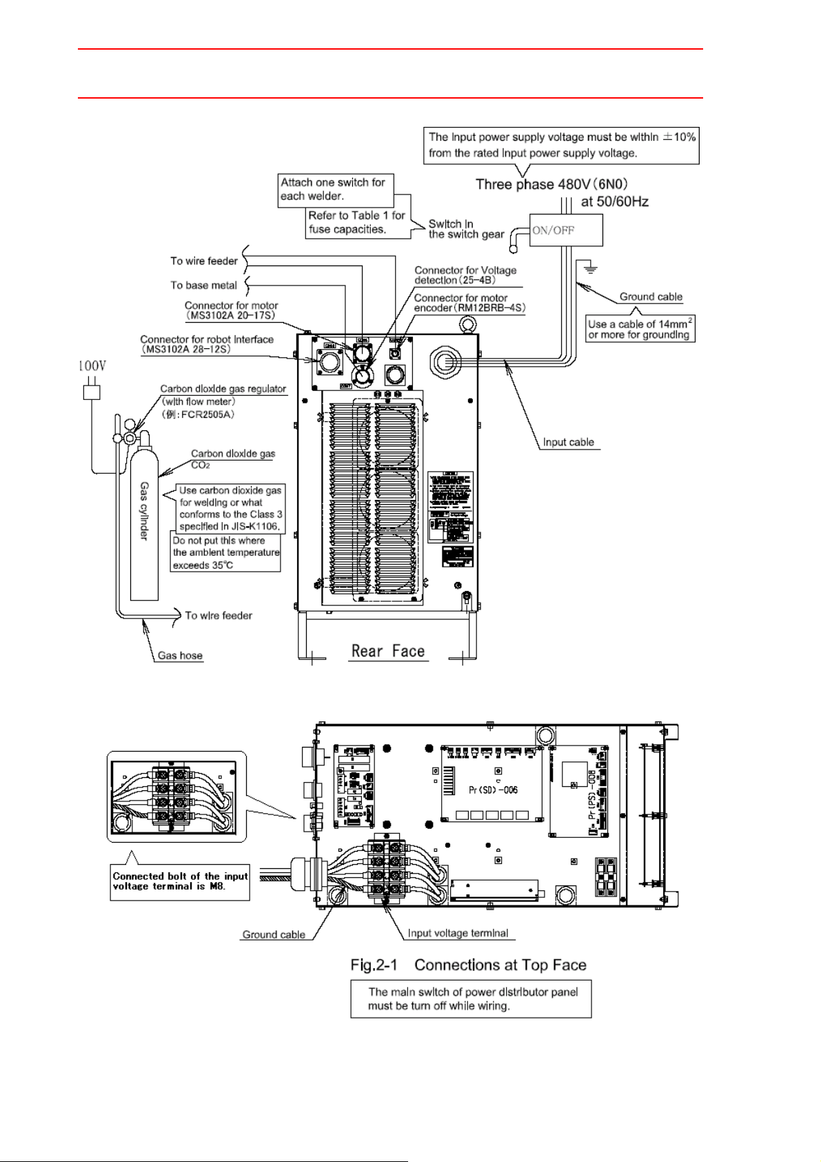
See " Fig. 1 Connection Diagram of Welding Source at Re ar Face " for proper connections.
1) Input cable
Please remove the top cover and connect the cable with the input terminal of
the partition board.
Connected bolt of the input voltage terminal is M8.
2) Ground cable
2. Connection on the Welding Side
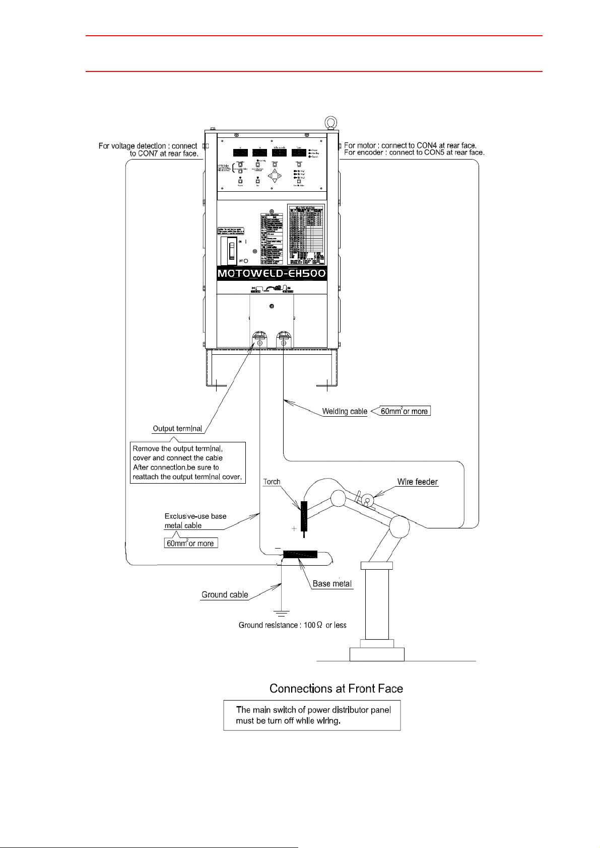
See " Fig. 2 Connection Diagram of Welding Source at Front Face " for proper connections.
1) Welding cable
The welding cable connects between the welding torch and power output termi-
2-3
HW0480311
Page 21

HW0480311
21/129
2.5 Connection of Electrical System
nal (+).
2) Exclusive-use base metal cable
The exclusive-use base metal cable connects between the base metal and
power output terminal (-).
3) Welding Voltage Detecting Line
The welding voltage detecting line connects between the base metal and connector "CON 7" at rear face of the welding source.
CAUTION
• Be sure to connect the welding voltage detecting line.
If the welding voltage detecting line is not connected, the error "Err70 2: Voltage Detection
Wire Error" may occur, and welding cannot be performed.
• Only if the length of the welding cable and exclusive-use base metal
cable is 5 m or less respectively, the welding source can be used with
connecting a short-circuiting cap for detecting voltage of output terminal (-) to the connector "CON 7" at rear face of the welding source. For
improving the welding performance, connect the base metal and connector "CON 7" with the welding voltage detecting line whenever possible.
3. Connection of Control Cable
Connect cables of every kind to connectors at rear face of the welding source. When
connecting the cables, securely tighten the plug until it stops rotating.
1) Connect the control cable of the robot controller to the connector "CON 3".
2) Connect the motor cable of the wire feeder to the connector "CON 4".
3) Connect the encoder cable of the wire feeder to the connector "CON 5".
2-4
HW0480311
Page 22
2.5 Connection of Electrical System
22/129
HW0480311
Acrobat 文書
Fig. 1 Connection Diagram of Welding Source at Rear Face
2-5
HW0480311
Page 23
HW0480311
23/129
2.5 Connection of Electrical System
Fig 2 Connection Diagram of Welding source at Front Face
2-6
HW0480311
Page 24
HW0480311
24/129
2.6 Connection of Welding Voltage Detecting Line
4. Grounding
Ground terminal is provided at the input voltage terminal in the partition board of the
welding source for safe operation. Connect the grounding cable of 14 mm
the crimp contact. Ground resistance must be 100
Be sure to ground the base metal at resistance of 100
in " Fig. 2 Connection Diagram of Welding Source at Front Face ". If it is not
grounded, voltage may be generated in the base metal resulting in electric shock.
Make sure that the grounding is always done individually , sep arated from grounding for
the manipulator. Also, connect the welding source and the base metal with exclusiveuse base metal cable.
Ω or less.
Ω or less individually as shown
2
or more to
2.6 Connection of Welding Voltage Detecting Line
In the connection of the welding voltage detecting line, Be sure to observe the following items
.If the following items are not observed, the amount of the spatter generation might increase.
1. Connect the welding voltage detecting line as close to the position where welding is
performed as possible.
2. The welding voltage detecting line and the welding output cable must separate as far
as possible.(The distance is required 100mm or more.)
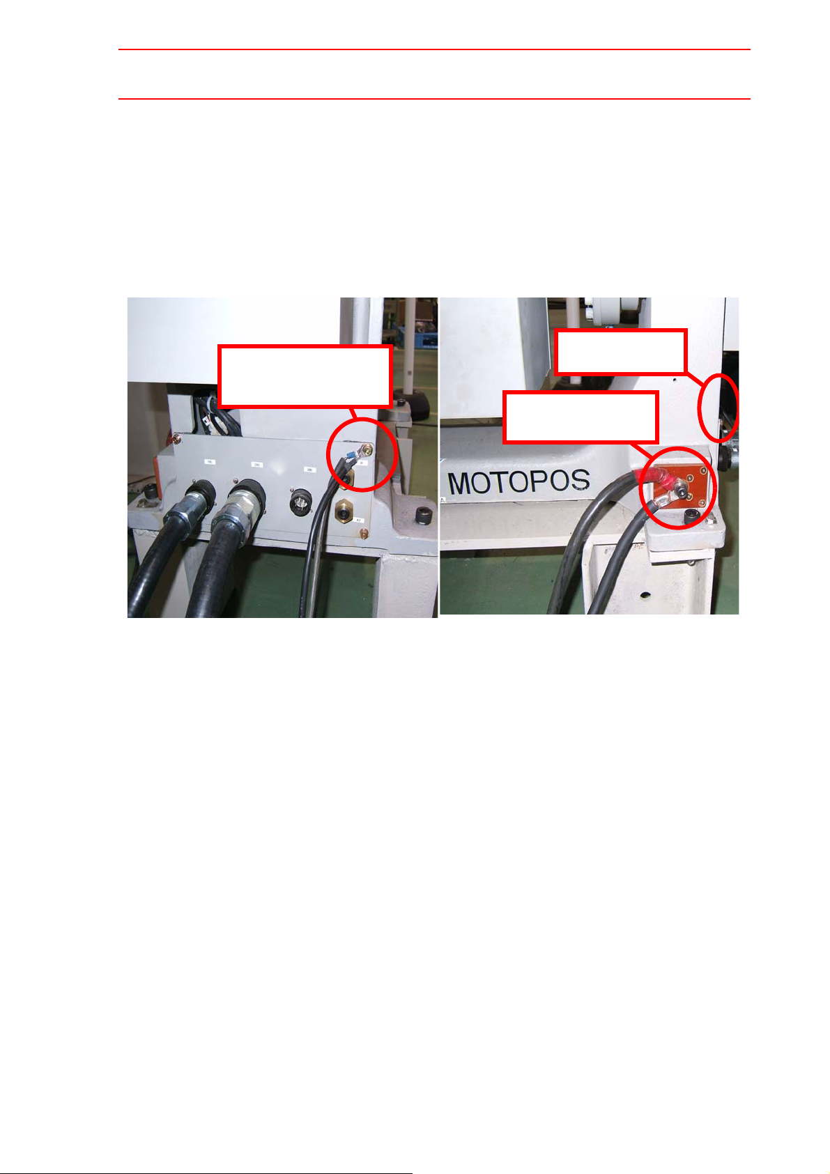
3. When you use MOTOPOS(external welding positioner), Connect the welding voltage
detecting line with with the screw of the cover that exists in the base of MOTOPOS.
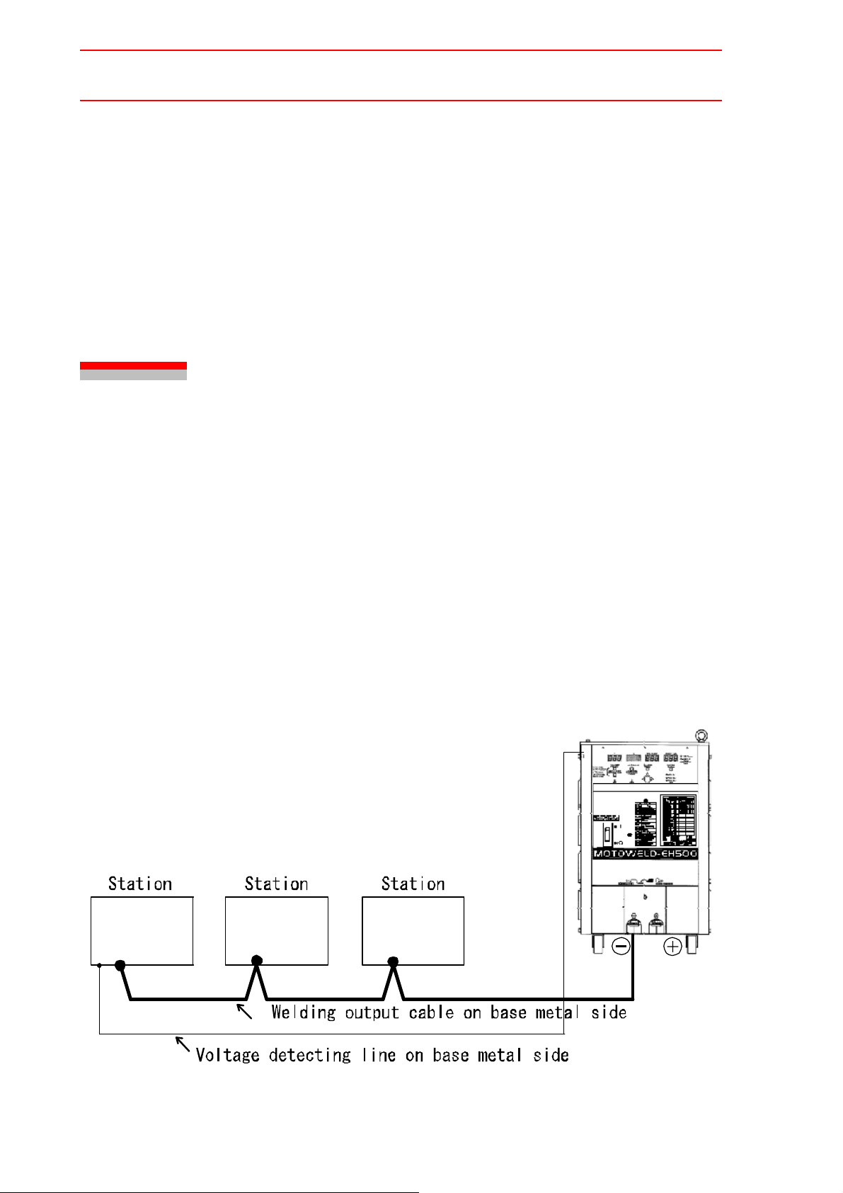
When two or more stations are used, connect the weldin g voltage detecting line with a station
as far away from the welding source as possible as indicated in " Fig. 2 Connection of Welding Voltage Detecting Line when Multiple Stations are Used ".
Fig. 2 Connection of Welding Voltage Detecting Line when Multiple Stations are Used
2-7
HW0480311
Page 25
HW0480311
25/129
2.6 Connection of Welding Voltage Detecting Line
When a rotation axis is used, connect the welding voltage detecting line with the screw of the
cover that exists in the base of MOTOPOS. Don’t connect output cable and the welding voltage detection line with the same part as indicated in " Fig. 3 Connection of Welding Voltage
Detecting Line when Rotation Axis and two welders is Used ".(Don't connect the welding voltage detection line with the route where the welding current flows).
Please confirm it has run electrically between the welding workpiece and the screw of the
cover by the tester before it wires.
-
Two voltage detect
Two voltage de
-
tecting lines
ing lines
Two welding out
-
put cables
(a) Connection of voltage detecting line (b) Connection of welding output cable
Fig. 3 Connection of Welding Voltage Detecting Line when Rotation Axis and two welders is Used
2-8
HW0480311
Page 26

HW0480311
26/129
2.6 Connection of Welding Voltage Detecting Line
When you use two or more welders, Connect the each welding output cable of the welder as
close to the position where welding is performed as possible.
Separate the welding output cable A from the welding voltage detecting line B,and separate
the welding output cable B from the welding voltage detecting line A as far as possible.(Distance between Cable A and cable B is required 100mm or more.)
Don't connect the welding voltage detection line with the route where the welding current flows
Fig. 4 Connection of Welding Voltage Detecting Line and Welding outputcable
when two or more welders are used.
CAUTION
• Be sure to connect the welding voltage detecting line.
If the welding voltage detecting line is not connected, the error "Err702: Voltage Detection
Wire Error" may occur, and welding cannot be performed.
• Only if the length of the welding cable and exclusive-use base metal
cable is 5 m at a maximum respectively, the welding source can be used
with a short-circuiting cap for detecting voltage of output terminal (-) on
the connector "CON 7" at rear face of the welding source. For improving
the welding performance, connect the base metal and connector "CON
7" with the welding voltage detecting line whenever possible.
2-9
HW0480311
Page 27
HW0480311
27/129
2.7 Connection of Shielding Gas System
2.7 Connection of Shielding Gas System
2.7.1 For Mixed Gas or Carbon Dioxide Gas Welding
The 100 VAC power supply is required for a heater of carbon dioxide gas regulator. Connect
the gas cylinder as follows:
1. Remove dust from the gas cylinder connecting port. Install the MAG/carbon dioxide
common gas regulator. Check the quality of the gas and the type of the cylinder.
2. Insert one end to the supplied rubber gas hose into the output of the gas regulator, and
the other end into the gas terminal inlet of the wire feeder. Clamp both ends securely
with hose bands.
2.7.2 Installation Site and Gas Cylinder Environment
Handle the gas cylinder with special care because it contains high pressure gas. Refer to the
instruction manual attached to the gas cylinder.
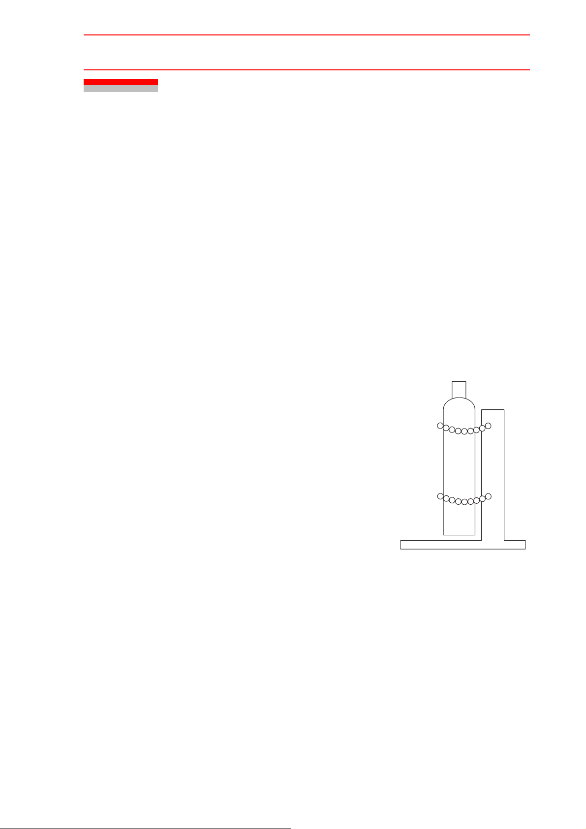
1. Installation SIte of Gas Cylinder
Place the gas cylinder in a specified gas container position that is not exposed to direct sunlight. If the gas cylinder is unavoidable placed at the welding site, it must
be fixed to post or cylinder stand in an upright position to
prevent it from falling. Also, the gas cylinder must not be
heated by a welding arc or the like.
2. Type of Gas Cylinder
Carbon dioxide gas-filled cylinders can be classified into
two types: one is the general type that is not the siphon
type, and the other is the siphon type.
Never use siphon type gas cylinders. The provided carbon dioxide gas regulator is not applicable to siphon
type cylinder. If the regulator is connected to a siphon
type gas cylinder, the contents of the cylinder are not
gaseous and enter the regulator as remaining liquefied.
In such a case, the pressure reduction mechanism of
the regulator cannot be operated. The type of gas cylinder can be distinguished by cylinder color according to
the cylinder’s manufacturer. Contact the gas distributor
for details.
The safety valve operates when the pressure goes
extremely high. When the valve operates, stop operation immediately, confirm the reason, and take appropriate corrective actions to prevent that the same error
occurs again.
Gas cylinder
Fix the gas cylinder to prevent
it from falling.
Fig. 5 Installation Site of Gas
Cylinder
Gas cylinder stand
2-10
HW0480311
Page 28

2.7 Connection of Shielding Gas System
28/129
3. Quality of Gas for Welding
Moisture or impurity in the carbon dioxide gas or argon gas used to shield welding arcs
adversely influenced welding. High purity and low moisture gas must be used.
Use MAG gas
containing 80 % argon and 20 % carbon dioxide gas for mixed gas.
The gas mixing ratio of MAG gas is content, which contributes to constant welding
quality. Especially for pulse welding, improper pulse welding will be resulted if the
argon gas ration is less than 80 %.
Use carbon dioxide gas
designated as "for welding" or what conforms to Class 3
specified in JIS-K1106 (moisture content 0.005 % or less) or the equivalent. Avoid
using carbon dioxide gas containing moisture more than 0.005 %, not only for the
adverse effect on welding, but also because it may cause clogging in the gas reg ulator
if the water content freezes.
4. Gas Regulator with Flow Meter
Use gas regulator with flow meter suitable for the gas to be used. The following table
show the examples of the gas regulator.
HW0480311
Table. 2 Gas Regulator with Flow Meter
No. Type Applicable Gas Remarks
1 FCR-2505A CO
2 FCR-225 CO
*1
The power supply for the heater is not provided with the welding source. Prepare a 10 0
VAC power supply for the heater of the gas regulator.
, MAG Meter: Indicates secondary pressure
2
, MAG, Ar Meter: Indicates primary pressure and
2
and flow amount
1
Heater: 100 VAC*
float-type flow amount
Heater: 100 VAC*
, 190 W
1
, 190 W
2-11
HW0480311
Page 29
HW0480311
29/129
2.8 Ambient Environment
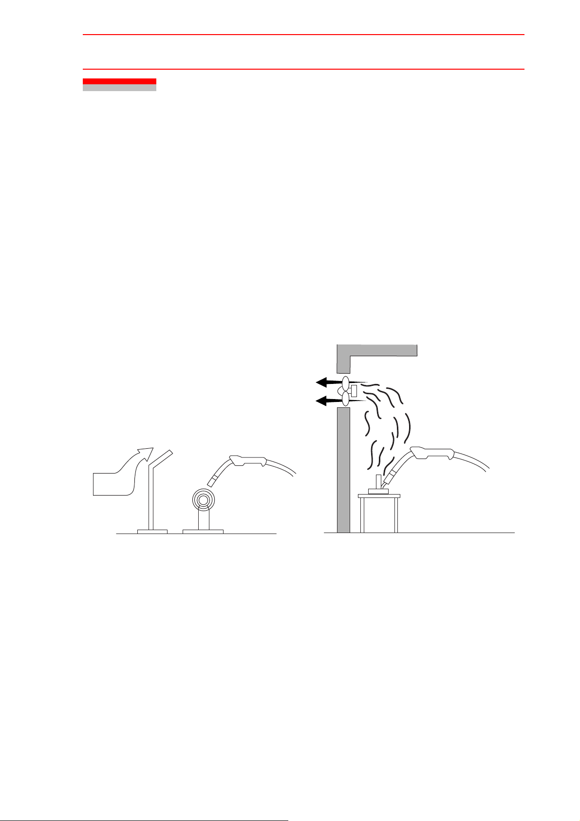
1. Wind Prevention
Normally, the allowable wind limit for welding using shielding gas is approx. 1.5 m/s or
less. If the wind speed is higher than this limit, stop operation or take some countermeasures such as putting up a screen.
Even for indoor operations, sufficient attention to the shield effect must be paid when
using air tools or fans around the welding.
2. Ventilation
The carbon dioxide gas used as the shielding gas is decomposed by arc heating, and a
small amount of carbon monoxide is generated.
For operations indoor or in a container or a t ank, ventilation is needed. In this case, do
not use a fan to blow the air, but ventilate the accumulated gas by providing a ventilation fan or exhaust duct.
2.8 Ambient Environment
Ventilating fan
Torch
Torch
Wind
Fig. 6 Shielding Wind for Welding
Screen
Object to be welded
Fig. 7 Ventilation Example
3. Shading Measures
For shaded glasses of helmets or hand shields, use filter numbers 8 to 10 of JIS T8141
for welding of thin plates since it has a weak arc beam and the arc must be seen easily.
Use numbers 10 to 13 for welding of medium-hick plates since the arc is bright. For
MAG welding, for which stronger arc light is required compared to CO
welding, use
2
greater filter numbers.
The welder brings in ultraviolet rays stronger than that caused by manual welding.
Periodically check protectors for eyes and the skin. Also, be sure to always wear these
protectors.
When the welding source is controlled by external control input signal or while operating the manipulator, provided proper shade around the welding torch.
Accidental arc generation may damage eyes or burn the skin of those without proper
protection.
2-12
HW0480311
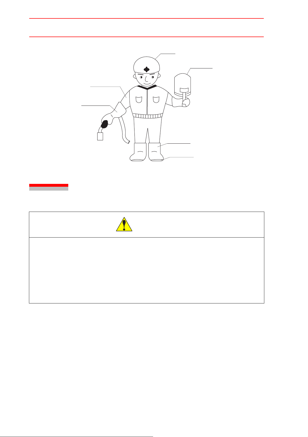
Page 30
2.9 Precautions on Transporting
30/129
Jacket must be
long-sleeved.
Welding gloves
HW0480311
Helmet
Handshield
Foot covers
Safety boots
Fig. 8 Protection Example
2.9 Precautions on Transporting
CAUTION
• Sling applications and crane or forklift operations must be performed by
authorized personnel only.
Failure to observe this caution may result in injury or damage.
• Avoid excessive vibration or shock while transporting.
The welding source consists of precision components. Failure to observe this caution
may affect its performance.
1. Transporting with Using Casters
When using the casters, move the welding source slowly so that it can be stopped
quickly at any time. Moving the welding source with casters quickly may result in an
accident due to inertia, and you cannot control the direction of movement.
Moreover, be sure to stop the welding source with casters at a ste p and move it slowly
to prevent any shock sudden. Do not move the welding source with casters up a slope,
stairs, etc.
2-13
HW0480311
Page 31

HW0480311
31/129
2. Transporting with Using a Crane
When using the crane, be sure to confirm the following points before transporting.
1) Confirme the mass of the welding source by referring to " 1 Basic Specifications
". Select the wire rope suitable for the mass and angle.
2) Use eyebolts for transporting and confirm that the eyebolts are tightened firmly
before transporting.
3) Lift the welding source using the crane after the above confirmation.
2.9 Precautions on Transporting
3. Transporting with Using a Forklift
Observe the following points to use the forklift for transporting.
1) Con firm availability of safe operations site, and transfer the weldin g source to the
installing site.
2) After determining the operation site, warnings must be placed on transport path
to prevent accidents.
3) Put the welding source on the transporting pallet and fix firmly to prevent falling
or shifting. Employ a stopper on the casters to fix the welding source.
Over-tightening the cover may cause it to deform.
4) Do not raise the lift excessively.
5) Avoid excessive shock or vibration while transporting since the system consists
of precision component.
6) Transport the welding source at yield speed when using the forklift.
2-14
HW0480311
Page 32

2.9 Precautions on Transporting
32/129
4. Others
1) Do not climb up on the welding source or place anything on it.
2) Do not p a ss a rope directly arou nd the welding source case durin g transporting .
Failure to observe this caution may deform the shape of the case or cause malfunction.
HW0480311
2-15
HW0480311
Page 33

HW0480311
33/129
3 Welding Preparation
The following table describes the preparation procedure to start actual welding.
Table. 3 Welding Preparation Procedure
Step Item Details
Setting welding wire Set a wire suitable to the welding method. Make sure
1
Checking torch Confirm that a contact tip suitable to the diameter of
2
that the diameter of the roller of wire feeder matches
the wire diameter.
the wire is installed on the torch.
Turning ON the switch in the
3
switch gear
Turning ON switches for the weld-
ing source
4
Setting feeding motor The feeding motor type can be set by the parameter
5
Confirm that connections are correct, then turn ON the
switch of the switch gear of the welding source.
Turn ON the power switch. The power indicator lamp
lights and the built-in cooling fan starts. The fan stops
after fifteen minutes unless the arc starts. The fan
automatically restarts when the arc starts.
C09.
0: Print servomotor (default setting)
1: Minertia servomotor for servo torch
2: 4-roller servomotor (YWE-WF340MELC)
Incorrect setting of the feeding motor precludes proper
welding because the wire cannot be fed at wire feeding speed as directed by the set value.
When the parameter was changed, follow the instructions as follows:
1. Keep on pressing the "Record" button for
more than three seconds to save changes.
Do not turn OFF the welding source while
saving.
2. Confirm that the 7-segment LED indicators
light again, then turn OFF the welding source
once and ON again.
For details, refer to " 4.2.8 Selecting Feeding Motor ".
Setting welding source voltage
control
6
Setting at the robot side Set the welding source condition files (including “Syn-
7
Set the welding source voltage control: either "Synergic (auto adjustment)" or "Independent (individual)".
When "Synergic" is set, the LED indicator lamp above
"Auto Adjustment/Individual" button will light up.
"Synergic (auto adjustment)" is set before shipping.
ergic (auto adjustment)” or “Independent (individual)”).
For details, refer to " 16 Welding Source Condition
File of the Robot Controller ".
3-1
HW0480311
Page 34

34/129
Table. 3 Welding Preparation Procedure
Step Item Details
HW0480311
Selecting welding type Before Setting;
the type of shielding gas and wire, or short-circuit/
8
Checking the indicated value on
the welding source panel
9
Wire inching Adjust the welding wire by wire inching so that it can
10
pulse.
Selectable types are written on the nameplate on the
front face of the panel. Set the welding type number to
the Type on the welding source panel.
Check the settings for the voltage, current, wire feeding speed, and welding type of the digital meter on the
welding source panel. Check the indicated value on
the panel by changing command value from the robot
controller.
be used for welding as follows:
1. Output the inching command from the robot
controller.
Select the welding type according to
2. Inch the wire until it comes out from the end of
the torch.
Adjusting gas flow Adjust the gas flow as follows:
1. Press the "Gas" button on the panel of welding source. The LED indicator lights and the
gas flows for 20 seconds. The gas automatically stops after the 20 seconds. (The gas
flow time can be set by the parameter C00.
Refer to " 4.2.7 Checking the Flow Amount of
11
Shielding Gas ".)
2. Turn the valve of the gas cylinder counterclockwise to open.
3. Turn the knob of the gas regulator to adjust
the flow according to welding conditions.
Proper gas flow rate is 10 to 25 liters per
minute. The flow rate must be increased in
proportion to the welding current (the higher
the current, the larger the flow rate).
Saving welding conditions Save the conditions before turning OFF the welding
source as follows:
1. Keep on pressing the "Record" button for
more than three seconds to save changes.
12
Do not turn OFF the welding source while
saving.
2. The 7-segment LED indicators light up again
at the completion of the saving. Confirm that
the 7-segment LED indicators light again.
End
13
3-2
HW0480311
Page 35

HW0480311
35/129
4.1 Explanation of Welding Source Panel
4 Operations on Panel
4.1 Explanation of Welding Source Panel
NOTE
Pressing the panel buttons during welding does not change any oper ation othe r than user
file selection.
Be sure to stop welding before starting the panel operations.
1
V
PRM Select
8
Common PRM Select
9
14
Record
2
A
Auto Adj.
Auto Adjustment
10
/Individual
15
Gas
3
Wire m/min
PRM Set
11
+
L
-
13
R
4
Type
Weld.Type
12
File No.1
File No.2
File No.3
16
User File Select
5
Power
Warning
Search
6
7
Fig. 9 Welding Source Panel
4-1
HW0480311
Page 36

4.1 Explanation of Welding Source Panel
36/129
The following table explains the display of the meters c, d, e, and f.
The content of the display differs according to the status as follows:
HW0480311
Status
During
standb
y
During welding
During wire inching
When
Parameter
C32=0,
Displays
Setting
Conditions.
When
Parameter
C32=1,
Displays
Stanby
V
c Welding Volt-
age Indicator
Displays the set
welding voltage
value (V).
Displays 0.0V Displays 0A Displays 0.0m/min Displays the weld-
Displays the welding voltage value
(V) that is fedback.
d Welding Cur-
rent Indicator
Displays the set
welding current
value (A).
Displays the welding current value
(A) that is fedback.
A
Wire m/min
e Wire Feeding
Speed Indi cator
Displays the feed-
ing amount (m/
min) of the set
welding current
value.
Displays the feeding amount (m/
min) of the motor
that is fed-back, or
the motor current.
(Can be switched
by the parameter
D1-5.)
Type
f Welding Type
Indicator
Displays the weld-
ing type (Type).
ing type (Type).
Displays the welding type (Type).
During setting parameter
Displays the
parameter number.
Normally displays
"---". When the arc
touch start is
selected, displays
"-" in the parameter P01.
Display Lamps
Item Content Explanation
g
h
i
Power Lamp Lights when the power supply is turned ON.
Warning Lamp Lights or blinks when an error occurs. The error number is dis-
played on the digital meter.
Search Lamp Lights while the starting point detecting function is used. High
voltage is being generated while the lamp is turned ON. ( E ffective only when the starting point detecting unit is installed.)
Displays
-P parameter:
ratio (%)
-C parameter:
value
(in decimal)
-D parameter
ON/OFF
Displays the welding type (Type).
4-2
HW0480311
Page 37

HW0480311
37/129
4.1 Explanation of Welding Source Panel
Setting Buttons
Item Content Explanation
j
k
l
11
12
Parameter Select
(P parameter)
Common Parameter
Select (C parameter)
Auto Adjustment/Individual (synergic/independent) Switch
Parameters Setting When setting parameters or common pa rameters, the numbers and
Selecting of Welding
Type
When the "PRM Select" button is pressed during standby status,
the display changes to the P parameter setting display. The 7-seg-
ment LED indicator
e displays the parameter set value. (Effective only when the
cator
user file is selected.)
Press this button again to return to the standby display.
When the "Common PRM Select" button is pressed during standby
status, the display changes to the common para meter setting dis-
play. The indicator
the common parameter set value.
Press this button again to return to the standby display.
Switches the control type of welding voltage.
-Auto adjustment: LED indicator lamp lights.
(Output voltage is set at % from the robot controller.)
-Individual: LED indicator lamp turns OFF.
(Output voltage is set by welding voltage command from the
robot controller.)
the parameter set values can be switched. The blinking 7-segment
LED indicator is the selected item.
Press the button "Weld Type" button during standby status to
change the welding type (Type), and the 7-segment LED indicator
c displays "P.00", and the 7-segment LED indi-
c displays "C.00", and the indicator e displays
12
f blinks. The welding type setting is confirmed with pressing of this
button again, and the 7-segment LED indicator
f stops blinking.
13
14
15
16
Right to Left or Up and
Down Move Button
Saving Conditions Used to save the setting. The LED indicator lamp blinks when the
Checking Gas Checks the gas. The LED indicator lamp lights when pressing the
Selecting of the User
File
Used to change the settings. Press "L" or "R" to move the digit.
Press "+" or "-" to increase or decrease the value.
setting is changed.
To save the changed setting, keep pressing the "Record" button for
three seconds or more. If the welding source is turned OFF when
the 7-segment LED indicators go out, the changed setting cannot
be saved successfully. Wait until the 7-segment LED indicators are
lit again. If the welding source is turned OFF and back ON af ter the
7-segment LED indicators are lit again (the conditions are saved),
the settings return to the status where the conditions were saved.
Turn the welding source OFF and back ON without pressing this
button so as not to save the changed settings.
"Gas" button, and the gas flows for 20 seconds. (The default setting
for the gas flow time is 20 seconds. This time can be changed by
C00 parameter.) When this button is pressed again during the gas
check, the gas stops flowing.
Selects the file to save the contents of the changed settings. Each
time the "User File Select" button is pressed, the LED indic ator
lamp for the file number is changed.
(No File→ File No.1→ File No.2→File No.3)
P parameters cannot be changed or saved without a file: "No File".
4-3
HW0480311
Page 38

4.2 Settings on Welding Source Panel
38/129
4.2 Settings on Welding Source Panel
4.2.1 Changing Welding Type
The following describes how to change the welding type.
(1) Press the button "Weld. Type", and the 7-segment LED indicator
blinks.
12
HW0480311
f "Type"
V
(2) Use the button "+" or "-" to increase or decrease the value. Use t he button "L"
or "R" to move the digit.
(3) After changing the value, press the button "Weld. Type" or leave it without doing
anything for 10 seconds, and the 7-segment LED indicator
V
Press the button "Record" for 3 seconds or more to save the changed value. Do
not turn OFF the welding source while pressing this button. The saving of conditions is completed when the 7-segment LED indicators are lit again.
13
14
A
A
Wire m/min
12
Wire m/min
Type
13
f "Type" lights.
Type
The welding types available for software version 3.20-000-6 (CPU) are listed on the
nameplate attached to the front panel of the welding source.
Welding types other than listed on the nameplate are not available. Using improper
welding type will result in unstable welding, which causes excessive spatters or
imperfect bead appearance. Before starting welding, confirm that the welding type
has been correctly selected.
4-4
HW0480311
Page 39

HW0480311
39/129
4.2 Settings on Welding Source Panel
Table. 4 List of Weld Types
Shielding Gas Wire
MAG
(Ar 80%, CO
20%)
MAG
(Ar 80%, CO
20%)
CO
2
MIG
(Ar 98%, O
2%)
2
2
2
Soft steel
Fe
Soft steel
Fe
Soft steel
Fe
Stainlesssteel
SUS
Pulse or
Short-circuit
Short-circuit
Pulse
Short-circuit
Short-circuit
Wire
Diameter
Weld
Type No.
φ 0.9 3.21
φ 1.0 3.24
φ 1.2 3.27
φ 1.4 3.61
φ 0.9 3.19
φ 1.0 3.22
φ 1.2 3.25
φ 1.4 3.60
φ 0.9 3.35
φ 1.0 3.36
φ 1.2 3.37
φ 1.4
3.62
φ 0.9 5.29
φ1.0 5.31
φ1.2 5.33
Remarks
MIG
(Ar 98%, O
2%)
MAG
(Ar 80%, CO
20%)
MIG
(Ar 98%, O
2%)
Ar
MIG
(Ar 92%, O
8%)
Welding types other than listed on the nameplate are not ava ila ble .
SUPPLE
-MENT
Using improper welding type will result in unstable welding,which causes excessive spatters or imperfect bead appearance.Before starting welding,confirm that the welding type
has been correctly selected.
Stainlesssteel
2
Pulse
SUS
Stainlesssteel
2
Pulse
SUS
SUS Pulse φ 1.2 4.43
2
Aluminum
Pulse φ 1.2 2.12
φ 0.9 5.46
φ 1.0 5.42
φ 1.2 5.44
φ 0.9 5.28
φ 1.0 5.30
φ 1.2 5.32
5000
Low pulse φ 1.2 2.14 Servo torch: Necessary
Mild steel
2
Fe
Zinc Pulse φ 1.2 3.59
Servo torch:
Recommended
For galvanized
sheet iron
4-5
HW0480311
Page 40

HW0480311
40/129
4.2 Settings on Welding Source Panel
4.2.2 User Files
The conditions changed by the P parameter concerning any welding type are saved in the
user files: File No. 1, File No. 2, and File No. 3.
Also, the user file can be called up from the manipulator controller to perform welding.
The P parameters cannot be changed or saved unless the user file is selected (No File status).
1. When the content of P parameter is to be changed, confirm that the user file can be
changed by the panel operation (D1 parameter D1-11=OFF), then select the user file:
file No. 1, 2, or 3. The file No. is changed each pressing of “User File Select” button,
16
and the LED indicator lamp of selected file lights. The file No. is changed as: No
File
ÆFile No.1ÆFile No.2ÆFile No.3.
2. Press the button “Weld.Type” to change the welding type (Type).
12
Refer to " 4.2.1 Changing Welding Type " for details on changing of the welding type.
When conditions are changed, the LED indicator lamp for "Record" blinks.
SUPPLE
-MENT
Keep pressing the button "Record" for three seconds or more to save the changed content. Do not turn OFF the welding source while pressing this button. The saving of conditions is completed when the 7-segment LED indicators are lit again.
14
CAUTION
• When the welding type which is set in the user file is changed, the P
parameters are initialized and everything becomes the value at 100 %.
4.2.3 Changing P Parameters
The P parameters are used for welding adjustment. The P parameters are changed by multiplying the internal set data of the selected welding type by the modification ratio. The change
of the P parameters is allowed only when the user file: file No.1, No.2, or No.3 is selected.
For details on the P parameter, refer to " 4.3 List of Process Parameters ".
Follow the instructions to change P parameter value as follows:
(1) Press the button
c voltmeter (V) displays "P.00" blinking, and the 7-segment LED indicator e
cator
j "PRM Select" during standby status. The 7-segment LED indi-
"Wire m/min" (WF) displays the parameter value lighting.
(2) Press the button "L" or "R" button to change the number of blinking digits to one.
Press the button "L" button to move the blinking to the left, and press the button
13
"R" to move the blinking to the right.
(3) Using the button “L” or “R”, move the blinking digits to the number to be
13
13
13
changed.
(4) Use the button “+” or “-“ to increase or decrease the value.
13
4-6
HW0480311
Page 41

HW0480311
41/129
4.2 Settings on Welding Source Panel
(5) Press the button “PRM Set”, and the parameter value on the 7-segment LED indi-
e “Wire m/min” blinks. The set value of parameter is ready to be changed.
cator
11
Change the set value in the range between 10 and 200 %.
For changing the parameter number, press the button “PRM Set” again.
The blinking digits move as shown below with each pressing of the button “PRM
11
11
Set”.
V
V
A
A
(6) After changing the value, press the button
Wire m/min
Wire m/min
j “PRM Set” or leave it without doing
Type
Type
anything for 10 seconds to return to the standby display.
Press the button "Record" for three seconds or more to save the changed values
14
(conditions). Do not turn OFF the welding source during saving conditions. When
the 7-segment LED indicators are lit again, the saving of conditions is completed.
4.2.4 Changing Common (C) Parameters
For the details on the common parameter, refer to " 4.4 List of Common Parameters ".
The C parameter is the common parameters for the welding source.
Follow the instructions to change C parameter value as follows:
(1) Press the button
LED indicator
cator
e "Wire m/min" (WF) displays the parameter value lighting.
(2) Press the button "L" or "R" to change the numb er of blinking digit s to one. Press
the button "L" to move the blinking to the left, and press the button "R" to
move the blinking to the right.
(3) Using the button "L" or "R", move the blinking digits to the number to be changed.
(4) Use the button "+" or "-" to increase or decrease the value.
k "Common PRM Select" during standby status. The 7-segment
c voltmeter (V) displays "C.00" blinking, and the 7-segment LED indi-
13
13
13
13
13
(5) Press the button "PRM Set", and the parameter value on the 7-segment LED
11
4-7
HW0480311
Page 42

4.2 Settings on Welding Source Panel
42/129
indicator e "Wire m/min" blinks. The set value of parameter is ready to be
HW0480311
changed. If the set value is four digits or more, use the button "L" to move the
cursor to the indicator
d ammeter (A). The indicator d ammeter (A) displays the
13
number(s) above the forth digit.
For changing the parameter number, press the button "PRM Set" again.
The blinking digits move as shown below with each pressing of the button "PRM
11
11
Set".
V
V
A
A
Wire m/min
Wire m/min
Type
Type
(6) After changing the value, press the button
k "Common PRM Select" or leave it
without doing anything for 10 seconds to return to the standby display.
Press the button "Record" for three seconds or more to save the changed values
14
(conditions). Do not turn OFF the welding source during saving conditions. When
the 7-segment LED indicators are lit again, the saving of conditions is completed.
4-8
HW0480311
Page 43

HW0480311
43/129
4.2 Settings on Welding Source Panel
4.2.5 Changing D Parameters
For details on the D parameter, refer to " 4.5 List of D Parameters ".
D parameters specify the setting or operation conditions for the welding source by ON/OFF.
The D parameters consist of D-1 parameter and D-2 parameter. The setting items for each
parameter are: No.1 to No.16, altogether 32 setting items are available.
Follow the instructions to change D parameter as follows:
(1) Keep pressing the button
Select" during standby status. The 7-segment LED indicator
plays "d-1" blinking, the 7-segment LED indicator
ware switch number blinking, and the 7-segment LED indicator
(WF) displays ON or OFF lighting.
k "Common PRM Select" and press the button j "PRM
c voltmeter (V) dis-
d ammeter (A) displays the soft-
e "Wire m/min"
(2) Use the button "+" or "-" to switch "d-1" and "d-2"
(3) The blinking digits move as shown below with each pressing of the button "PRM
13
11
Set".
V
V
V
A
A
A
Wire m/min
Wire m/min
Wire m/min
Type
Type
Type
Use the button "L","R", "+", or "-" to change the parameter number and the set
13
contents.
When the 7-segment LED indicator
d ammeter (A) is blinking, the software switch
numbers (1 to 16) can be selected.
When the 7-segment LED indicator
e "Wire m/min" is blinking, the setting of soft-
ware switch (ON/OFF) can be changed. ON and OFF are switched with each press-
ing of the button "+" or "-".
(4) After changing the setting, press the button
13
k "Common PRM Select" or leave it
without doing anything for 10 seconds to return to the standby display.
4-9
HW0480311
Page 44

4.2 Settings on Welding Source Panel
44/129
<Example>
When the parameter D1-11 is ON (enabled):
HW0480311
V
Press the button "Record" for three seconds or more to save the changed values
14
A
Wire m/min
Type
(conditions). Do not turn OFF the welding source during saving conditions. When
the 7-segment LED indicators are lit again, the saving of conditions is completed.
4.2.6 Saving Welding Conditions
When the parameter set value is changed by the operations on the welding source panel, the
LED indicator lamp above the button "Record" blinks.
The following describe how to save the settings.
(1) Referring to " 4.2.2 User Files ", specify the file number where the data are to be
saved.
(2) Press the button "Record" for 3 seconds or more, and the 7-segment LED indica-
14
tors display dashes "- - -".
(3) When the saving is completed, the 7-segment LED indicators returns to the status
where the conditions were saved.
If the power supply is turned OFF while saving the welding conditions, the data cannot be successfully saved. Confirm that the 7 segment LED indicators are lit again
before turning OFF the power supply.
14
CAUTION
• For P parameters, the changed data are validated at the same time the
change is made. However, when the welding type is changed or the
power supply switch of the welding source is turned OFF, the changed
data will be lost.
The changed data are overwritten on the da ta of the file where the data
are to be stored.
4-10
HW0480311
Page 45

HW0480311
45/129
4.2 Settings on Welding Source Panel
4.2.7 Checking the Flow Amount of Shielding Gas
The shielding gas flow amount can be checked.
Press the button "Gas" button. The LED indicator lamp above the "GAS" button lights and
the gas flows for 20 seconds.
Press the button again during gas checking to stop the gas flow.
The checking time of the gas flow amount can be adjusted by change in the numerical value
of C parameter C00, while, the default setting is 20 seconds (unit: second).
Press the button "Record" for 3 seconds or more to save the changed value.
15
14
NOTE
Do not turn OFF the breaker until the 7-segment LED indicators are lit again when the
“Record” button was pressed.
4.2.8 Selecting Feeding Motor
The feeding motor can be selected by change in the numerical value of C parameter C09.
C09: 0 Print servo (Default setting)
C09: 1 Servo torch
C09: 2 4-roller servo
Press the button "Record" button for 3 seconds or more to save the changed value.
To validate the change in setting, turn OFF the welding source and ON again after saving the
conditions.
NOTE
Do not turn OFF the breaker until the 7-segment LED indicators are lit again when the
“Record” button was pressed.
14
(YWE-WF340MELC)
CAUTION
• Welding performance will be unsatisfactory, since the wire cannot be
fed at the wire feeding speed as instructed by the command value
unless the feeding motor is set correctly.
• The change in the motor setting will be first reflected when the welding
source is restarted (turned OFF
Æ ON) after saving the conditions.
4-11
HW0480311
Page 46

HW0480311
46/129
4.2 Settings on Welding Source Panel
4.2.9 Monitoring of Motor Current
The motor current of rotating feeding motor can be displayed in the 7-segment LED indicator
"Wire m/min" by setting D parameter D1-5 to "OFF". During the standby status, the 7-segment LED indicator displays the command of wire feeding amount (m/min).
V
When the 7-segment LED indicator displays the motor current, "A" is indicated at the third digit
of the indicator.
In the figure above, the motor current is 0.5 A.
When the 7-segment LED indicator does not display "A" at the third digit, D paramete r D1-5 is
set to "ON" status, and the indicator shows the feedback speed of wire feeding.
There are two levels for monitoring the motor current: the warning level and the error level.
• Motor current warning
Outputs a warning signal when the motor current exceeds the warning level which has
been set by C parameter C25. Wire feeding and welding will be continued although the
motor current exceeds the warning level. The warning signal will be output through the
terminals 524 and 525 on the Pr(RC2)-001 board.
• Motor current error
Outputs Err502 "motor overcurrent" and ends wire feeding and welding when the motor
current is passed more than the rated current.
A
Wire m/min
Type
4.2.10 System Reset
System Reset initializes all the setting data in the welding source. Reset the system only when
the software is updated or initialization or when Memory Error (Error 205 to 299) occurs.
CAUTION
• Be sure that executing System Reset initializes all the internal data.
If some parameters must be retained, write them down on a sheet of
paper before System Reset. The data cannot be restored after the system reset operation.
4-12
HW0480311
Page 47

HW0480311
47/129
The following describes how to reset the system.
(1) Press the button
LED indicator
cator
e "Wire m/min" (WF) displays the parameter value lighting.
k "Common PRM Select" during standby status. The 7-segment
c voltmeter (V) displays "C.00" blinking, and the 7-segment LED indi-
4.2 Settings on Welding Source Panel
V
(2) Use the button "+", "-", "L" or "R" to display the parameter "C23".
V
(3) Press the button "PRM Set", and the parameter value on the 7-segment LED
indicator
e "Wire m/min" blinks. Change the setting value of parameter "C23" to
13
11
A
A
Wire m/min
Wire m/min
"2004". When the setting value is four digits or more , use the button "L" to move
the cursor to the 7-segment LED indicator
d ammeter (A). The indicator d amme-
Type
Type
13
ter (A) displays the number(s) above the forth digit. The system reset will be executed at C23=2004.
Wait until "sys rst" starts blinking.
V
A
Wire m/min
Type
(4) Turn OFF the welding source when "sys rst" is displayed. This is end of the initial-
ization.
V
A
Wire m/min
Type
(5) Turn ON the power supply and the parameters retu rn to the de fault setting. Set the
recorded parameters again if necessary.
4-13
HW0480311
Page 48

HW0480311
48/129
4.2 Settings on Welding Source Panel
4.2.11 Lock Of Panel Operation
"Lock of panel operation" is a function to invalidate the button operation so as not to operate
the button of a front panel of the welding power supply by mistake. The button that can be
operated with the panel operation locked is only a gas check button.
Method of setting "lock of panel operation"
R button is pushed continuousness three times while pushing L button.
V
PRM Select
Common PRM Select
Record
A
Auto Adj.
Auto Adjustment
/Individual
Gas
Wire m/min
LR
After the condition is stored, HOLd is displayed.
V
A
Type
PRM Set
Weld, Type
File No.1
File No.2
File No.3
User File Select
Wire m/min Type
Power
Warning
Search
If "HOLd" is displayed, "lock of panel operation" is set.
In the state of "lock of panel operation", only the gas check button can be operated.
HOLd "is displayed when buttons other than the gas check button are pushed, and the button
operation is not accepted.
4-14
HW0480311
Page 49

HW0480311
49/129
4.2 Settings on Welding Source Panel
Method of releasing "lock of panel operation"
L button is pushed continuousness three times while pushing R button with the panel
operation locked.
V
PRM Select
Common PRM Select
Record
A
Auto Adj.
Auto Adjustment
/Individual
Gas
Wire m/min
PRM Set
LR
Type
Weld, Type
File No.1
File No.2
File No.3
User File Select
Power
Warning
Search
After the condition is memorized, and 7- Segment LED lights again, "lock o f panel operation"
has been released.
All the button operations of a front panel become possible.
4-15
HW0480311
Page 50

HW0480311
50/129
4.3 List of Process Parameters
4.3 List of Process Parameters
The welding characteristics (start/main conditions/end) that are specified by database in the
welding source can be adjusted according to your environmental conditions by changing the
set values of the process parameters (P parameters).
All the values are set to "100% = Operating as the characteristics in the database" before
shipping.
If the adjustment of welding characteristics is required, refer to " 13 Process Parameters
(Adjustment of Welding Characteristics) "
Display
*1
No.
P00
C Wire slow-down speed
P01
C Wire speed at start
P02
C Starting pulse peak current
P03
- Reserved for system Do not change.
P04
C Starting pulse peak time
P05
C Average value of hot current
P06
C Average value of hot voltage
P07
CHot time
P08
P Pulse current
P09
P Base current
P10
P Pulse time
Items Description
P11
C Average current at ending VALID when the parameter D1-4=ON
P12
C Average voltage at ending VALID when the parameter D1-4=ON
P13
C End time VALID when the parameter D1-4=ON
P14
C Average current value at burning
P15
C Average voltage value at burning
P16
C Burning time
P17
C Droplet pulse peak current
P18
C Droplet pulse peak time
P19
- Reserved for system Do not change.
P20
C Wire-stick prevention time
4-16
HW0480311
Page 51

HW0480311
51/129
4.3 List of Process Parameters
Display
*1
No.
P21
- Reserved for system Do not change.
to
P30
P31
P MAG/MIG pulse current increas-
ing speed
P32
- Reserved for system Do not change.
P33
P MAG/MIG pulse current decreas-
ing speed
P34
- Reserved for system Do not change.
P35
A Aluminum MIG pulse current
increasing ratio
P36
A Aluminum MIG pulse current
decreasing ratio
P37
S Short-circuit current increasing
speed 1
Items Description
P38
S Short-circuit current decreasing
speed 2
P39
- Reserved for system Do not change.
P40
- Reserved for system Do not change.
P41
- Reserved for system Do not change.
P42
- Reserved for system Do not change.
P43
C Hot slope time
P44
C Ending slope time
P45
- Reserved for system Do not change.
P46
- Reserved for system Do not change.
P47
- Reserved for system Do not change.
P48
- Reserved for system Do not change.
P49
S Arc control 1
P50
S Arc control 2
P51
S Arc control 3
P52
- Reserved for system Do not change.
to
P54
4-17
HW0480311
Page 52

4.3 List of Process Parameters
52/129
HW0480311
Display
*1
No.
P55
A Low-pulse frequency ratio
(for welding type 2.14, aluminum)
P56
A Low-pulse wire feeding speed
ratio
(for welding type 2.14, aluminum)
P57
- Reserved for system Do not change.
to
P59
P60
C Synergic voltage adjustment
(automatic adjustment)
P61
P Arc length control gain
P62
C Current output characteristic 1 Wire feeding speed compensation ratio 1 (unit: %)
P63
C Current output characteristic 2 Wire feeding speed compensation ratio 2 (unit: %)
P64
- Reserved for system Do not change.
to
P67
Items Description
Changes the frequency based on C parameter C03.
E.g.)
When C03=100 and P55=50%, 5.0Hz
Changes the amplitude based on C parameter C04.
E.g.)
When C04=10 and P55=200%, C04*200%=20%
Compensates the voltage by 1V with
±10%.
*1 P: For pulse welding (including aluminum pulse)
A: For aluminum welding
S: For short-circuit welding
C: Common for all the welding types
4-18
HW0480311
Page 53

HW0480311
53/129
4.4 List of Common Parameters
4.4 List of Common Parameters
Common parameters (C parameters) specify the operations of the welding source. Set the
parameters according to the operation conditions.
Save the changed common parameters to enable common parameters. Then turn OFF the
power and ON again.
Display
No.
C00
C01
C02
C03
C04
C05
C06
C07
C08
C09
C10
C11
C12
C13
C14
C15
C16
C17
Contents
Gas check time
Gas pre-flow time
Gas after-flow time
Low-pulse frequency (for welding type 2.14, aluminum)
Low-pulse amplitude (for welding type 2.14, aluminum)
Current at low-pulse acceleration (for welding type 2.14, aluminum)
Current at low-pulse deceleration (for welding type 2.14, aluminum)
Digital meter displayed speed
External resistance set value
Motor setting
Reserved for system
Reserved for system
Reserved for system
Current calibration reference
current 1 (File 1)
Current calibration reference
current 2 (File 1)
Current calibration reference
current 1 (File 2)
Current calibration reference
current 2 (File 2)
Current calibration reference
current 1 (File 3)
Default
Setting
20 s
56 ms
500 ms
100 0.1Hz
20 %
120 %
100 %
1000 ms
505
2-
50
100
200
150 A
250 A
150 A
250 A
150 A
Unit Description
×10
*1
5
Ω
−
Gas flowing time before welding
output starts (minimum: 56 ms)
Gas flowing time after welding output completes
Low-pulse frequency
Low-pulse wire feeding speed
amplitude
Current at low-pulse acceleration
Current at low-pulse deceleration
Time for average moving for display of current/voltage digital
meter
Electric resistance value of weld-
-
ing current path such as power
cable, jig stand connected to welding source
Motor selection
0: Print-type servomotor (default
setting)
1: Minertia servomotor for servo
torch
2: 4-roller servomotor (YWE-
WF340MELC)
Do not change.
Do not change.
Do not change.
Reference current 1 for the user
file No.1
Reference current 2 for the user
file No.1
Reference current 1 for the user
file No.2
Reference current 2 for the user
file No.2
Reference current 1 for the user
file No.3
4-19
HW0480311
Page 54

4.4 List of Common Parameters
54/129
HW0480311
Display
No.
C18
C19
C20
C21
C22
C23
C24
C25
C26
C27
C28
C29
C30
C31
C32
Contents
Current calibration reference
current 2 (File 3)
Reserved for system
Reserved for system
Reserved for system
Reserved for system
System Reset
Reserved for system
Motor current warning value
Reserved for system
Reserved for system
Error: outside the range of out-
put current
Setting range of the error: outside the range of output current
Reserved for system
running time of Cooling Fan
after welding
Digital Meter Display during
stanby
Default
Setting
250 A
0
0
41
0
0
0
70
48
600
0
70 A
80
900 s
0
Unit Description
Reference current 2 for the user
file No.3
Do not change.
Do not change.
Do not change.
Do not change.
When the C parameter C23 is set
to "2004", System Reset is executed to initialize all parameters
(default setting).
Before executing System Reset,
record the modified parameters.
After executing System Reset, turn
OFF the welding source and turn
ON again.
When the power supply is turned
OFF, the C parameter C23 is back
to "0".
Do not change.
% (for
motor
rated
current
The value at which the warning is
output for the excess current of
feeding motor
)
Do not change.
Do not change.
0: If the output current is outside
the range, the error (Err790,
Err791) is issued after welding.
1: If the output current is outside
the range, the error (Err790,
Err791) is issued during welding
and the welding stops.
2: If the output current is outside
the range, the error is not
issued.
Sets the range of the error: out side
the range of output current
(Err790, Err791).
If the output current is within the
range of welding current command
±C29, the error is not issued. If it
exceeds the range, the error:
Err790, Err791 is issued.
Do not change.
When setting 30000(max
value),Cooling Fan always runs.
Set Digital meter display during
stanby.
0: Displays setting conditions.
1: Displays stanby status
(0.0V,0A,0.0m/min)
4-20
HW0480311
Page 55

HW0480311
55/129
4.5 List of D Parameters
Display
No.
C33
Contents
Reserved for system
Default
Setting
0
Unit Description
Do not change.
*1 The initial value of the external resistance set value is the value measured under the
environment for the MOTOWELD-EH500 database creation. For measurement of the
external resistance value under your operation conditions, refer to " 14 Calibration for
External Resistance ".
4.5 List of D Parameters
D parameters specify the operation conditions for the welding source. Set the parameters
according to the operation conditions.
The D parameters are displayed by following the instructions as follows: Keep pressing the
button
k "Common PRM Select" and press the button j "PRM Select" during standby status.
D-1
Display
No.
1
2
3
4
5
6
7
8
9
10
11
12
13
14
15
16
Reserved for system Do not change. OFF
Reserved for system Do not change. ON
Wire slow-down Enabled Disabled ON
End event End condition process-
Display of feeding speed/
motor current
Reserved for system Do not change. OFF
Reserved for system Do not change. ON
Reserved for system Do not change. ON
Reserved for system Do not change. ON
Data communication
mode
User file switching Switched at robot side Switched on panel OFF
Reserved for system Do not change. OFF
Reserved for system Do not change. OFF
Reserved for system Do not change. ON
Reserved for system Do not change. OFF
Reserved for system Do not change. ON
Contents ON OFF
End condition process-
ing enabled
Displays feeding speed Displays motor current ON
Enabled Disabled OFF
ing disabled
Default
Setting
ON
4-21
HW0480311
Page 56

4.5 List of D Parameters
56/129
D-2
Display
No.
1
2
3
4
5
6
7
8
9
10
11
12
13
14
15
16
External resistance calibration
Touch start User File1 Enabled Disabled (normal start) OFF
Touch start User File2 Enabled Disabled (normal start) OFF
Touch start User File3 Enabled Disabled (normal start) OFF
Reserved for system Do not change. ON
Reserved for system Do not change. ON
Reserved for system Do not change. ON
Reserved for system Do not change. ON
Reserved for system Do not change. OFF
Reserved for system Do not change. OFF
Reserved for system Do not change. OFF
Reserved for system Do not change. OFF
Reserved for system Do not change. ON
Reserved for system Do not change. ON
Error Latch Error Latch until the
Reserved for system Do not change. OFF
Contents ON OFF
*1
Compensates by external resistance value set
in the parameter C08
power is turned OFF
HW0480311
Default
Setting
Disabled OFF
Automatic error reset OFF
*1 To enable the calibration for the external resistance value, the external resist ance value
must be measured. For measurement of the external resistance value under your
operation conditions, refer to " 14 Calibration for External Resistance ".
*1
• Always set the parameter "D1-10" to "disabled" (OFF) at times other than data communications.
• For aluminum welding, it is recommended to set the parameter for the end event "D1- 4"
to "enabled" (ON) since automatic crater processing is effective. The crater processing
requires approx. two seconds after ARCOF instruction. Set additionally the Timer instruction so that the manipulator stops for two seconds at the welding end point.
• For synergic voltage, the voltage that Yaskawa assumes adequate is specified as 100%.
Changing the synergic voltage by 10%, voltage varies by approx.about 1V. (Example: In
case of 20V at 100%, it becomes 19V and 21V at 90% and 110%, respectively. The percentage (%) can be changed in the range between 50% and 150% (±5V).) The percentage (%) that is set at robot synergic voltage is displayed on the welding source in the unit
of V.
• For the welding type: CO
short-circuit arc welding, do not use the touch start but select
2
the normal start.
• When aluminum welding is selected, the touch start arc becomes enabled (default set-
4-22
HW0480311
Page 57

HW0480311
57/129
ting) with the parameters "D2-2", "D2-3", and "D2-4" set to "OFF".
4.5 List of D Parameters
4-23
HW0480311
Page 58

HW0480311
58/129
5.1 Checking the Welding Conditions
5 Welding Operation
5.1 Checking the Welding Conditions
Before starting actual welding operation, perform the test welding for welding conditions to
check if the welding performance is satisfactory. Remove oil, rust, oil paint, water, and foreign
matter generated by gas-cutting to prevent the surface pore and blowhole.
5.2 Wire Stickout
The wire length from the torch tip to the arc point is called wire stickout. Keep this length
constant during welding.
The following table shows the length ( ) of wire stickout as standard.
Length ( ) of wire stickout
Wire Diameter
(1.2 mm)
15 mm 10 to 15 mm 20 mm
Wire Diameter
(0.9 mm)
Wire Diameter
(1.4 mm)
5.3 Direction of Welding and Torch Angle
There are two welding types: backhand welding (same as manual welding), in which the torch
is tilted by 0° to 10° in the direction of welding, and forward welding, in which welding is
carried out in the same state but in the opposite direction. The forward welding is more
popular in robot welding because it results in better gas shielding and the welding can be
performed viewing the welding line.
0°
10°
Torch
Wire stickout
Forward
welding
Gas
Forward welding is preferred in CO2/MAG welding.
Nozzle
Backhand
welding
Base metal
5-1
HW0480311
Page 59

HW0480311
59/129
5.4 Precautions on Using Extension Cable
Fig. 10 Direction of Welding and Torch Angle
5.4 Precautions on Using Extension Cable
When an extension cable is used, actual output between the torch and the base metal
decreases because of voltage drop in the cable. To prevent this, set the command value of
welding voltage adjustment higher than the target voltage value to compensate for the output
voltage drop. " Fig. 11 Reference for Voltage Drop along Extension Cable " shows a
reference for the voltage drop along an extension cable.
Use the one-class thicker extension cable to keep stable welding voltage.
Voltage
drop (V)
Voltage
drop (V)
4
2
0
4
2
0
100 200 300 500
Welding current (A)
100 200 300 500
Welding current (A)
Extension cable length
(one way)
25m
15m
Extension cable length
(one way)
Fig. 11 Reference for Voltage Drop
along Extension Cable
20m
10m
25m
15m
10m
20m
This graph indicates the relationship
between voltage drop and welding
current when an extension cable of 60
2
mm
is used. If extension cables are
used for both ways, the voltage drop
becomes twice as much as the value
indicated in this graph.
This graph indicates the relationship
between voltage drop and welding
current when an extension cable of 80
2
mm
is used. If extension cables are
used for both ways, the voltage drop is
twice as much as the value indicated in
this graph.
SUPPLE
-MENT
• If an extension cable is used for pulse welding, the response for the pulse waveform control may be delayed, which may prevent the spatter-less pulse welding. Use a cable as
short as possible for high quality welding.
• In order to compensate for the voltage drop due to extension cables, etc., perform automatic correction by the calibration of the external resistance value which is described in "
14 Calibration for External Resistance ".
5-2
HW0480311
Page 60

HW0480311
60/129
6.1 Error Detection Function
6 Precautions on Welding
6.1 Error Detection Function
Error detection is performed for the following items, and the welding source is automatically
stopped when an error is detected.
If an error occurs, the "Warning" lamp lig hts or blinks and the error number is displayed in the
digital meter on the panel face. For the contents of errors, refer to the following table.
At error detection, an arc failure signal is output at the robot side.
Table. 5 List of Error Display Contents
Error No. Item Contents Remedy
Err001 Input over-
voltage
Err002 Input under-
voltage
Err102 Excessive
temperature
Err107 Input/output
overcurrent
Err110 Voltage
detector error
Primary input voltage exceeding
550 V is applied continuously for
two seconds.
Primary input voltage is lower
than 390 V continuously for two
seconds.
The temperature in the primary or
secondary control circuit exceeds
the specified value of the welding
source.
Overcurrent flows in the primary
control circuit.
The welding voltage is not
detected.
Check the input voltage.
Check the input voltage.
• Check the ambient temperature
°C or less) and operational
(40
ratio (100 %).
• Check if there are dust, dirt, and
clogging on the dust protective
filter. Clean or replace the dust
protective filter if necessary.
• Check if the output cable is
short-circuited or grounded.
• The power circuit may be broken. Contact your Yaskawa
representative.
Contact your Yaskawa representative.
Err111 Auxiliary cir-
cuit overcurrent
Err203
and 204
CPU error A commu nications error betwee n
Overcurrent flows in the auxiliary
circuit.
the CPU1 and the CPU2 occurs.
6-1
The board may be broken. Contact your Yaskawa representative.
The board may be broken. Contact your Yaskawa representative.
HW0480311
Page 61

HW0480311
61/129
6.1 Error Detection Function
Table. 5 List of Error Display Contents
Error No. Item Contents Remedy
Err205 to
299
Err303 Panel switch
Err304 to
309
Err501 Improper
Memory error An error occurs in the data in the
setting error
Improper
model setting
feeding
amount
welding source internal memory .
The DIP switch of PR(CR)-008
board is not correctly set.
Nonconformity in the model setting of hardware and software
The welding wire was not fed as
instructed by the feeding amount
command value.
There is a certain difference
between the feeding amount
command value and the feedback from the encoder.
The data may not have been correctly saved when the welding
conditions are recorded because
of a power failure, etc. Reset the
system after saving the changed
parameters. (See " 4.2.10 System Reset ")
If the error occurs again, the
board may be broken. Contact
your Yaskawa representative.
• Check the DIP switch setting of
PR(CR)-008 board.
• PR(CR)-008 board may be broken. Contact your Yaskawa
representative.
The setting of hardware or software may not be performed correctly. Contact your Yaskawa
representative.
Check the following.
• Check that the encoder cable is
not damaged.
• Check if the screws of the connector terminal block are
securely fastened. If the
encoder cable is disconnected
or the screws are loosened, the
wire feeding speed becomes
excessively fast and an error
occurs in the wire feeding
amount. Replace the encoder
cable or fasten the screws of
the connector terminal block.
• Check if the wire load becomes
heavy . Make sure that th e torch
cable and conduit cable are not
bent excessively.
Err502 Motor over-
current
Err601 Starting sig-
nal error
Overcurrent above the rated current flows in the motor circuit.
Arc starting signal is input before
the welding source’s main power
supply starts up.
6-2
Check if the wire load becomes
heavy. Make sure that the torch
cable and conduit cable are not
bent excessively.
Check again the operation timing
or signal cable connections. The
same error may occur at momentary power failure.
HW0480311
Page 62

6.1 Error Detection Function
62/129
Table. 5 List of Error Display Contents
Error No. Item Contents Remedy
HW0480311
Err701 Output over-
current
Err702 Voltage
detection wire
error
Overcurrent flows in the secondary control circuit.
The welding voltage is not
detected.
Confirm the following.
• Check that the torch cable or
power cable is not grounded.
• Check that the contact tip does
not contact the workpiece to be
welded. Set the contact tip so
as not to contact the workpiece, then perform welding.
• Check that the encoder cable is
not damaged.
• Check if the screws of the connector terminal block are
securely fastened. If the
encoder cable is disconnected
or the screws are loosened, the
wire feeding speed becomes
excessively fast and an error
occurs in the wire feeding
amount. Replace the encoder
cable or fasten the screws of
the connector terminal block.
• Check if the voltage detection
wire is connected. Check if the
voltage detection line or the
short-circuit cap is connected to
the connector CON7.
• Check that the contact tip does
not contact the workpiece to be
welded. Set the contact tip so
as not to contact the workpiece.
• Temporary power failure may
have occurred.
Err790 Outside of
output current setting
(Over the
upper limit)
Err791 Outside of
output current setting
(Over the
lower limit)
The actual welding current
becomes far removed from the
welding current command value.
6-3
• Check if the selection of motor
is correct, or confirm the settings of C parameter C09.
• Check that the welding wire
does not slip, or the wire is fed
as instructed by the feeding
command.
• Check that the wire stickout is
not excessively short or long.
• Check that the range set in C
parameter C29 is not too narrow.
• Check if the wire, shielding gas,
welding type, earthing, etc. are
correctly set.
HW0480311
Page 63

HW0480311
63/129
6.2 Tripped Power Supply Switch
6.2 Tripped Power Supply Switch
If the power supply switch is tripped, do not turn it ON again. Contact your Yaskawa
representative. If the power is turned ON again with the power supply switch tripped, the
problem may be compounded and may affect the welding.
6.3 Precautions on Welding Operation
Check the following precautions before starting welding.
1. The welding wire is electrically charged during welding. Be careful that the welding
voltage still remains for two seconds after the welding ends due to the two-second
delay set for the welding source. Also, do not touch the welding wire during the st arting
point detection (optional function) since the voltage of approx. 300 V is applied to the
wire.
2. If a conduit cable is extremely bent, the welding wire cannot be smoothly fed, and thus
the set welding conditions may be altered. To prevent this, place conduit as straight as
possible.
3. If welding is performed at a current exceeding the rated output current, internal p arts of
the welding source may be burnt. Allowable operational ratio for a current under the
rated value is calculated as follows:
Allowable operational ratio = Rated operational ratio
Table. 6 Allowable Operational Ratio of the Welding Source of 500 Ampere
(with Rated Operational Ratio of 100%)
Welding
Current
(A)
500 100 Continuous welding possible
Allowable
Operational Ratio
(%)
Allowable Continuous
Welding Time
× [ ]2%
Rated current
Operating current
Welding Pause Time
6-4
HW0480311
Page 64

HW0480311
64/129
6.3 Precautions on Welding Operation
4. Power switch operation
The inverter welding source is the forced air-suction cooling type. Do not turn OFF the
power supply switch until the cooling fan completely stops after co mpletion of the o peration. To prevent electric shock, never disconnect or connect the cables for the welding source, the wire feeder, the welding torch, etc. while the power is ON. Make sure
that the power supply switch of the welding source is turned OFF after the operation.
5. Cooling fan
The cooling fan starts rotating as soon as the power supply is turned ON. Then, the
fan stops if approx. 15 minutes passes without arc start. However, the fan restarts
rotating when welding starts, and it stops approx. 15 minutes after the welding ends.
One of three fans operates at all times in sync with the power supply switch.
6. Stretch a protective curt ain around the welding ope ration space for workers and oth ers
to protect from arc light, spatter, and slag.
7. Installation Environment
Do not weld on a wet earth floor or metallic floor to avoid electric shock. Also avoid
welding where there are inflammables to prevent fire due to scattering of heated spatter or slag.
8. The welding source cannot be used for gouging other than CO
9. Radio disturbance
Noise may be generated over the radio during welding.
When listening to the radio, keep the radio as far as possible from the welding source.
When a radio is not on battery but on a 100 VAC power supply, do not bring the welding torch close to the 100 VAC cable.
/MAG welding.
2
6-5
HW0480311
Page 65

HW0480311
65/129
7.1 Internal Selecting Switches
7 Built-in Functions
7.1 Internal Selecting Switches
The internal selecting switches are set as follows before shipping.
The internal switches are not allowed for change since the switches are prepared for adjustement and maintenace performed by manufacturers.
Table. 7 DIP Switch Setting for Pr (CR)-008 Board
DIP Switch (DSW) Default Setting Remarks
1-8 OFF
1-7 OFF
1-6 OFF
1-5 OFF
1-4 OFF
1-3 OFF
1-2 OFF
1-1 OFF
2-8 OFF
2-7 OFF
2-6 OFF
2-5 OFF
2-4 OFF
2-3 OFF
2-2 OFF
2-1 OFF
3-8 OFF
3-7 OFF
3-6 ON
3-5 OFF
3-4 OFF
3-3 ON
3-2 ON
3-1 OFF
4-8 OFF
4-7 OFF
4-6 OFF
4-5 OFF
4-4 OFF
4-3 OFF
4-2 OFF
4-1 OFF
7-1
HW0480311
Page 66

HW0480311
66/129
7.2 Location of Printed Boards
ON
OFF
87654321
DSW1
87654321
DSW2
Fig. 13 DIP Switch Settings for Pr (CR)-008 Board
87654321
DSW3
87654321
DSW4
Pr (CR)-008
CAUTION
• Be sure not to switch the selecting switch which is designated as
"switch disabled" by mistak e. Failure to observe this caution may result
in a trouble.
7.2 Location of Printed Boards
Fig. 14 Top View without the Top Cover from the Welding Source
7-2
HW0480311
Page 67

HW0480311
67/129
7.2 Location of Printed Boards
Fig. 15 Location of Printed Board Pr(MB)-021 and Pr(CR)-008
To Replace Printed Board Pr(MB)-021 and Pr(CR )- 00 8 , Remove two screws at a control panel
and open a control panel.
7-3
HW0480311
Page 68

HW0480311
68/129
7.2 Location of Printed Boards
7.2.1 DIP Switch Settings for Pr(MB)-021 Board
The DIP switch settings for Pr(MB)-021 board are for manintenance. Do not change these
settings.
Table. 8 Settings of DIP Switches
SW1 Setting
1ON
2OFF
3ON
4OFF
7.2.2 Jumper-pin Settings of the Pr(MB)-021 Board
The settings of the Pr(MB)-021 board are for maintenance. Do not change these settings.
Table. 9 Settings of Jumper Pins
(no mark) Open Circle Side
SW5
SW6
SW7
SW8
H
H
5
R
7-4
HW0480311
Page 69

HW0480311
69/129
8.1 Daily Inspection Items
8 Maintenance and Inspection
WARNING
• Before maintenance or inspection, or wiring, be sure to turn OFF the
switch in the switchgear on the input side and put up a warning sign.
(ex. DO NOT TURN THE POWER ON.)
Failure to observe this warning may result in electric shock or injury.
• For internal inspection immediately after using the welding source, the
capacitor in the welding source may be charged. Wait for approx. five
minutes and remove the cover for inspection.
Failure to observe this warning may result in electric shock or injury.
CAUTION
• Maintenance and inspection must be performed by specified personnel.
Failure to observe this caution may result in electric shock or injury.
Perform periodical maintenance and inspection for safe and efficient operations of the weld ing
source.
8.1 Daily Inspection Items
Check the following:
(1) The switches operate without fail.
(2) The cooling fan rotates smoothly by turning ON/OFF the power supply switch and
draws the air in from the rear face.
(3) There is no abnormal vibration, beat, or odor.
(4) There is no leakage of gas.
(5) The cable connecting section is not excessively heated.
(6) The welding cable and its connecting section is not excessively heated.
(7) There is no damage on the connection cable such as a cable on the input side or on
the base metal side, resulting in imperfect insulation.
(8) Each connecting section is tightened securely.
8-1
HW0480311
Page 70

8.2 Bimonthly to Semiannual Inspection Items
70/129
8.2 Bimonthly to Semiannual Inspection Items
Perform the following:
(1) Removal of dust and dirt
Remove dust and dirt by spraying dry compressed air. Carefully clean spaces
between the transformer and reactor windings, and semiconductors.
To clean circuit boards, use the exclusive-use dust remover device.
(2) Inspection of electric connecting sections
Check that the bolts are firmly tightened and rust or the like does not deteriorate the
contacts in the connecting sections with the external wiring such as input/output terminals or with the internal wiring. Retighten the bolts if necessary or use a file to
remove rust, if any, so that the metallic faces contact with each other.
HW0480311
(3) Inspection of ground line
Confirm that the case is grounded properly.
8.3 Annual Overhaul and Repair
Carry out the integrated repair such as replacement of defective components, case repair,
and reinforcement of insulation deteriorated parts. Insulation resistance must be 1MΩ or
more between the control unit circuit and the case; if it is less than 1MΩ, the insulation of the
deteriorated part must be repaired.
8-2
HW0480311
Page 71

HW0480311
71/129
8.4 Guideline for Service Lifetime and Replacement of Components Used
8.4 Guideline for Service Lifetime and Replacement of
Components Used
The welding source is composed of many components. Unless all these components operate
normally, the welding source cannot utilize its essential functions. Therefore, it is absolutely
necessary to find any sign leading to a failure of a component or device as early as possible
according to the periodical inspection and take proper corrective action.
These components cannot be used continuously for ever. Even under normal operation
status, they are apt to have variation of the characteristics or malfunction after the life elapses.
Therefore, it is recommended that the component s be re placed periodically so th at the welder
can operate at optimum performance.
Normally, refer to the following guideline of the component replacement when the welding
source is used in the rated specifications (8 hours a day, 250 days a year).
• Electrolytic capacitor: Approx. 5 years
• Cooling fan: Approx. 5 years
• Breakers, relays: Depends on how often they are used. It is recommended that they be
8-3
HW0480311
Page 72

HW0480311
72/129
8.5 Replace Fuse
8.5 Replace Fuse
If any fault shown below occurs,Check fuse.If Fuse blown again after replace fuse,Contact
your Yaskawa representative.
Table. 10 Fuse
Item Fault
Fuse 10A blown.(purple
color)
Fuse 5A blown. • Although power switch is ON,the Digital Meter does not dis-
• Although the start signal is ON or the wire inching signal is
ON,Motor does not operate.
• Cooling fan does not rotate.
play .
To Replace Fuse 5A, Remove two screws at a control panel and open a control panel.
8-4
HW0480311
Page 73

HW0480311
73/129
9.1 Confirming Setting conditions
9 Failure Analyses
WARNING
• Before maintenance, inspection, or wiring, be sure to turn OFF the
switch in the primary side switch gear and put up a warning sign. (ex.
DO NOT TURN THE POWER ON.)
Failure to observe this warning may result in electric shock or injury.
CAUTION
• To connect a nylon connector, insert the connector after matching the
connector number and confirm that it is locked. Do not apply excessive
force to the printed board when inserting the connector. Never change
the positions of the internal wiring or modify the connections.
Failure to observe this caution may result in device problems.
Confirm that the junctions between the metal receptacle and the cable, and the connectors on
the printed boards are connected securely. Then, take corrective action by referring to "
Table. 11 Check Items ", " Table. 12 Failure Analyses for Welding Section ", and " Table. 13
Fault Analyses for Electrical Circuit Section ". If the equipment does not function properly
even after the corrective action, contact your Yaskawa representative to investigate the cause
and to repair as soon as possible.
9.1 Confirming Setting conditions
If any fault occurs, check the following items in " Table. 11 Check Items ". Afterwards, take
proper corrective actions in " Table. 12 Failure Analyses for Welding Section "."
Table. 11 Check Items
Item Contents
Welding type Check if the welding type suitable for material and the wire diameter or shielding
gas has been selected.
Parameter Check that changing of parameters does not le ad to the error in welding operation.
After recording the changed parameters , return the data to the initial values and
check how welding is performed.
9-1
HW0480311
Page 74

9.1 Confirming Setting conditions
74/129
Table. 11 Check Items
Item Contents
HW0480311
Synergic/
Independent
selection
Motor selection
Voltage
detection wire
P Parameters cannot
be changed.
User files
cannot be
selected.
Check if synergic/independent (auto adjustment/individual) se lection of the welding
source is the same as that on the robot sid e. Synerg ic/Indepe ndent o f the weldin g
source can be set by the panel button
ing source panel. When "synergic (auto adjustment)" is selected, the LED indicator
"Auto Adj." lights. If the setting is different from that on the r obot side, incorrect
welding voltage value is displayed on the pane l. Furthermore, if the welding source
condition files of the robot are not correctly set, the robot command values are not
correctly displayed on the welding source panel.
Confirm the set value of C parameter C09 to check if the motor is correctly
selected. (0: Print servo 1: Servo torch, 2: 4-roller servo (YWE-WF340MELC))
If the motor is not correctly selected, the wire is not fed as instructed by the command value and welding performance becomes unsatisfactory.
If the voltage detection wire is disconnected, the 7-segment LED indicator for welding voltage
ERR702 "Voltage detection wire error" is displayed on the 7-segment LED indica-
tors. Check if the voltage detection wire is correctly connected.
P parameters are effective only when the user file is selected. Select the user file
File 1, File 2, File 3) when using P parameters.
D parameter D1-11 is used to specify whether the user file is selected from the
panel or the robot. (D1-11 OFF: from panel, ON: from robot)
c on the welding source panel displays approx. 0 V. Then the error
l "Auto Adjustment/Individual" on the weld-
Record of
conditions
Encoder
cable
Shielding gas Check if the shielding gas suitable for the welding type is selected. For pulse weld-
Arc monitor When the arc monitoring function is used, refer to " 17 Setting of Arc Monitoring
After selecting the welding type or changing the parameter, save conditions before
turning OFF the welder power supply. Before recording conditions, be sure not to
select other welding type while the user file is being adjusted because the changed
data on P parameters are deleted.
When the encoder cable is disconnected, or whe n th e ph as es A and B are connected inversely, the wire feeding becomes excessively fast or the motor runs
inversely. In addition, the 7-segment LED indicator for wire feeding speed
plays 0 and the error Err501 "Improper feeding amount" is issued. Check the connection of encoder cable.
ing, the argon ratio must exceed 80% to execute one pulse per drop. If short-circuit
occurs excessively during pulse welding, check the argon ratio.
Function ". The parameter set value is different from the MOTOWELD-S350.
e dis-
9-2
HW0480311
Page 75

HW0480311
75/129
9.2 Cause and Remedy of Welding Sec tion Failure
9.2 Cause and Remedy of Welding Section Failure
Table. 12 Failure Analyses for Welding Section
Fault Cause Remedy
Blowholes
and pits
occur.
Excessive oil, rust, or paint
adheres to the base metal.
Oil adheres to the welding wire.
Or rust occurs.
Sufficient shielding gas does
not flow.
Gas shielding in the welding
section does not properly work
due to wind, etc.
Spatters adhere to the nozzle
and the gas does not flow out
smoothly.
The quality of the shielding gas
is poor.
The nozzle is too far from the
arc point.
Carefully remove the adherent substances to
clean the base metal.
Carefully store and handle the welding wire.
Remove the oil or rust from the feeding roller or
conduit.
Check for gas leakage. Also check that the gas
regulator has been correctly adjusted and th e ga s
cylinder is not empty.
When the wind blows hard, stop the operation or
use a screen, etc. to help block the wind.
Often remove the spatters from the nozzle and
apply spatter preventive agent to the interior of the
nozzle.
Replace the shielding gas with one of better quality.
Keep the proper length of the wire stickout (10 mm
to 25 mm) to perform welding. Increase the gas
flow amount.
9-3
HW0480311
Page 76

9.2 Cause and Remedy of Welding Section Failure
76/129
Table. 12 Failure Analyses for Welding Section
Fault Cause Remedy
HW0480311
Arc is
unstable.
Power supply voltage excessively fluctuates.
Chip hole diameter becomes
larger and worn.
Welding wire is not fed
smoothly.
Voltage between phases of the
3-phase power supply is not
balanced.
The welding conditions are not
correct.
Unstable arc tends to occur
when thin-plate or small-current
welding is performed only with
carbon dioxide gas.
Use a different power supply from that of other
machines that cause power supply voltage fluctuation. Or increase the power supply transformer
capacity.
Replace the chip. (Use a genuine chip.)
Remove the dust or iron powder choking up the
feeding roller section or conduit.
Check that the conduit is not excessively bent and
that the liner, contact tip, and feeding roller match
the wire diameter.
Use a different power supply from that of other
machines that cause the imbalance. Or increase
the power supply transformer capacity.
Use the test arc to increase or decrease the settings of the welding current value and voltage
value.
Use gas mixed with carbon dioxide gas and argon
gas to improve the arc behavior.
Excessive
spatters
The connecting section is
loose.
Voltage drop is excessive with
the extension cable.
The polarities of the secondary
terminal are inverted.
Jig current conduction is poor. Correct the contact between the jig and the base
The welding conditions are not
correct.
Welding wire is not suitable for
the shielding gas.
The status of the base metal is
poor.
The welding section is distorted.
Check each terminal connection and the conn ec tions with the base metal. Securely re-tighten if
necessary.
Shorten the extension cable’s length.
Use a thicker cable. Use the extension cable without bending it.
Correct the connection of + and -.
metal.
Increase or decrease the settings of the welding
voltage and current values to adjust the welding
conditions.
Check if a welding wire suitable for the welding
type is used.
Check the groove forms or dirt of the base metal.
Replace them with one of higher accuracy .
Check each terminal connection and the conn ec tions with base metal. Polish the contacting face
and tighten them securely.
9-4
HW0480311
Page 77

HW0480311
77/129
9.2 Cause and Remedy of Welding Sec tion Failure
Table. 12 Failure Analyses for Welding Section
Fault Cause Remedy
Bead form
is bad and
the appearance is
poor.
Arc-start is
poor.
Manipulation of electrode is not
correct.
The shielding gas has a problem.
The welding conditions are not
correct.
Welding current conduction is
not perfect.
The connection cable is too
thin.
The welding conditions are not
correct.
The status of the base metal is
poor.
Change the welding torch angle a little. Employ
the forward welding method and practice so that
welding torch can constantly aim at a target. Or
change the welding speed.
Since the gas flow amount is not sufficient, let the
gas flow 10 to 25 litters per minute, and mix argon
gas if necessary. Or use a gas of better quality.
Increase or decrease the settings of the welding
voltage or current value a little.
Check the connections and the current conduction
contacting section of the base metal to confirm the
current conduction.
Replace the cables at the 3-phase input side and
base metal side with those of sufficient thickness.
Check that the welding voltage set value is not too
small or that the wire feeding speed set value is
not too large.
Check that dirt or insulating material does not
adhere to the base metal or slugs do not remain
on it.
Burnback
occurs.
(The welding wire
sticks to the
end of the
contact tip.)
The welding torch operations
are not correct.
The power cable is wired with
the cable being winded.
The welding torch operations
are not correct.
The welding conditions are not
correct.
Contact tips are defective. Check that the contact tip hole is worn and its
Welding current conduction is
not perfect.
The welding wire almost buckles.
The wire stickout of the welding wire is too long.
Shorten it a little. Change the welding torch angle.
Or slow down the welding speed.
Wire the power cable as straight as possible.
The wire stickout of the welding wire is too short.
Extend it a little. Change the welding torch angle.
Check that the welding voltage set value is not too
large or that the wire feeding set value is not too
small.
inner diameter has become too big. Also ch eck for
defect on the tip inner side.
Check the connections and the current conduction
contacting section of the base metal to confirm the
current conduction.
Pull the welding wire from the inside of the conduit
and pass the welding wire again through the conduit.
9-5
HW0480311
Page 78

HW0480311
78/129
9.3 Cause and Remedy of Failure at Electrical Circuit Section
9.3 Cause and Remedy of Failure at Electrical Circuit
Section
Table. 13 Fault Analyses for Electrical Circuit Section
No. Failure Cause Remedy
Power supply indicator lamp does
1
not light even if the power supply
switch is turned ON.
Cooling fan
does not
rotate even if
power supply switch is
turned ON.
2
The welding source does not
start although the start signal is
turned ON.
3
Power supply
indicator lamp
lights.
Power supply
indicator lamp
does not light.
Power supply indicator lamp
failure, improper contact
Cooling fan or control circuit
failure
Fuse F1, F2 (5A) blown Investigate the cause and
Fuse (10 A) on the board
Pr(SD)-006 blown
Power supply indicator lamp
failure, improper contact
The start signal is not sent to
the welding source.
Check contacting sections. Replace the power
supply indicator lamp.
Check the cooling fan
and the printed board
(MB)-021 and (SD)-006.
replace the fuse.
Investigate the cause and
replace the fuse (10 A)
on the board Pr(SD)-006.
Check contacting sections. Replace the power
supply indicator lamp.
• Check for the welding
command cable.
• Check for insertion of
the connector (CR4) on
the printed board (CR)-
008.
Although the
start signal is
ON, only the
motor does
not operate.
3
Welding current (welding current
5
command) cannot be changed
from the robot side.
Voltage is
applied to the
motor terminals
(between #A and
#B of the connector CON4)
The voltage is
not applied to the
motor terminals
(between #A and
#B of the connector CON4).
Motor failure Replace the motor.
Disconnection of the device
control cable, or improper
contact of the connector
Fuse (10A) on the board
Pr(SD)-006 blown
Printed board (SD)-006 failure
The analog command sent
from the robot side is not normal.
Replace the device control cable or check contacting sections.
Upon investigating the
error cause, replace the
fuse (10A) on the printed
board Pr(SD)-006.
Check and replace the
printed board (SD)-006.
Check the analog command output on the robot
side.
9-6
HW0480311
Page 79

HW0480311
79/129
9.3 Cause and Remedy of Failure at Electrical Circuit Section
Table. 13 Fault Analyses for Electrical Circuit Section
No. Failure Cause Remedy
Welding voltage (welding voltage
6
command) cannot be changed
from the robot side.
Error indication on the digital
7
meter
The power supply switch is
tripped and the power is not
8
turned ON.
Shielding gas cannot be adjusted
or stopped.
9
The analog command sent
from the robot side is not normal.
See " Table. 5 List of Error
Display Contents ".
Damage to the input diode Contact your Yaskawa
Damage to the main circuit
transistor (IGBT)
Failure of the gas solenoid
valve
Fuse (10 A) on the board
Pr(SD)-006 blown
Failure of the printed board
(SD)-006
The printed board (SD)-004
is installed by mistake.
(The printed board (SD)-004
cannot be used.)
Check the analog command output on the robot
side.
See " Table. 5 List of
Error Display Contents ".
representative.
Investigate the gas system.
Upon investigating the
error cause, replace the
fuse (10 A) on the printed
board Pr(SD)-006.
Check or replace the
printed board (SD)-006.
Replace the board with
the printed board (SD)-
006.
The starting point detection cannot be detected.
10
The starting point detection
command is not sent to the
welding source or the power
supply for starting point I/F is
not supplied to the welding
source.
The starting point detection
signal is not sent from the
welding source.
Check the connection
signal cable.
9-7
HW0480311
Page 80

HW0480311
80/129
10.1 Specifications of Robot Interface Signals
10Robot Interface Signals
10.1 Specifications of Robot Interface Signals
The following table shows the correspondence of the pin number and the signal of connector
CON3 (26 pins).
For signal systems, refer to “11. Conncetion System Diagram.”
Pin No.
No.
Correspon
ding to
Connector
Signal
Meaning
Function
Direct
*1
ion
Signal
Form
- B
A
1
2
3
4
5
6
(0V side)
- D
C
(0V side)
- G Wire inching
F
- J Wire retract
H
- L ARCON/
K
- N
M
("-" side)
Arc voltage
adjustment
instruction
Welding current instruction
instruction
instruction
ARCOF
instruction
Wire stick
detection
Gives the compensation value of the arc
voltage when set to "Synergic."
(When set to "independent," the arc voltage is sent directly.)
Gives the set value of the output current
(wire feeding amount) for the welding
source.
Performs the wire inching.
Withdraws the wire.
Instructions to start/stop the welding.
Sends the output terminal voltage of the
welding source.
The wire stick detection voltage
(approx.15 V) is input from the robot side.
R
W
R
W
R
W
R
W
R
W
W
R
→
→
→
→
→
→
Analog
voltage
input of
0V to 14V
Analog
voltage
input of
0V to 14V
Contact
input
(Valid at
closed)
Contact
input
(Valid at
closed)
Contact
input
(Valid at
closed)
Welding
source
output
voltage
(Analog
value)
10-1
HW0480311
Page 81

HW0480311
81/129
No.
Pin No.
Correspon
ding to
Connector
Signal
Meaning
10.1 Specifications of Robot Interface Signals
Function
Direct
*1
ion
Signal
Form
- E
P
(COM)
7
- E
R
(COM)
8
Arc occurrence detection
Arc failure
detection
1. The signal is output when the current
is detected continuously for 16 ms
after the gas pre-flow upon receiving
the arc start signal.
2. If the current is not detected for 48 ms
or more continuously after the signal is
output, the signal stops being output.
3. (1) and (2) are repeated.
The signal stops being output at the same
time as the wire stick prevention voltage
ends.
1. The signal is output when the arc st ar t
is not detected for 1.5 seconds after
the gas pre-flow upon receiving the
arc start signal.
2. After the arc occurrence is detected
within 1.5 seconds, the signal is output
when the arc occurrence is not
detected for 0.6 seconds or more continuously.
3. After the arc failure is detected, the
states described in (1) and (2) are selfmaintained until the start command of
welding source is released.
4. The signal is output also when an
error occurs in the welder.
W
R
W
R
→
→
Contact
output
(Valid at
closed)
Contact
output
(Valid at
closed)
- E
S
9
10
11
12
(COM)
- E
T
(COM)
E (536) Common Common for detection line
W - X Monitoring
Reserved
Reserved
output for
output current
Sends the monitoring signal of the output
current.
3.0V/600A
Note: When using the arc monitoring
function, refer to " 17 Setting of Arc
Monitoring Function ".
W
R
W
R
W
R
W
R
→
→
→
→
Contact
output
(Valid at
closed)
Contact
output
(Valid at
closed)
Return
line of
contact
output
Analog
voltage
10-2
HW0480311
Page 82

10.1 Specifications of Robot Interface Signals
82/129
Pin No.
No.
Correspon
ding to
Connector
Signal
Meaning
Function
Direct
*1
ion
HW0480311
Signal
Form
U - V Monitoring
13
b - Z User file
14
Y - Z User file
15
a - Z Gas check
16
Z (531) Common
17
output for
output voltage
selection
OP1
selection
OP2
GAS
COM
Sends the monitoring signal of the output
voltage.
3V/60V(66V for 66V or more)
Note: When using the arc monitoring
function, refer to " 17 Setting of Arc
Monitoring Function "
Externally switches the user file selection
by connecting each signal to common (Z).
Note: Connected to the pin terminals:
"OP1" and "OP2" of the standard
welding instruction cable.
To externally switch the user file,
set D parameter D1-11 to "ON".
Turns ON/OFF the gas solenoid valve by
connecting to common (Z).
Note: Connected to "GAS" pin terminal of
the standard welding instruction
cable.
Common of OP1, OP2, and GAS signals
Note: Connected to "COM" pin terminal of
the standard welding instruction
cable.
W
R
R
W
R
W
R
W
→
→
→
→
Analog
voltage
+24V
±10%,
current
capacity
of 50mA
or more
+24V
±10%,
current
capacity
of 50mA
or more
Return
line of
contact
input
*1 "R" indicates the robot side while "W" indicates the welding source side.
The voltage for wire stick detection which is output from the robot sid e does not ap pear on the
welding source panel.
10-3
HW0480311
Page 83

HW0480311
83/129
10.2 Meaning and Function of Pr(RC2)-001 Terminal
10.2 Meaning and Function of Pr(RC2)-001 Terminal
The following describe the cable number of the connection terminal block and corresponding
signals.
10.2.1 TB2 Terminal
20W
10K
TB2
209
211
526
Ω
527
A
V
Connection
No.
1209
2211
3526
4527
5
6
Terminal
Block Cable
No.
−
−
*1
"R" indicates the robot side while "W" indicates
the welding source side.
Signal
Meaning
Ammeter
terminal
Voltmeter
terminal
Reserved
Function
Outputs 600A,
60mV.
Directly outputs
the output
voltage.
−−
Directi
*1
on
→R
W
→R
W
NOTE
The external meters connected to the TB2 terminal are analog mete rs of ammeter (600A /
60mV) and voltmeter (75V). Values of the ten's volts for wire stick or ground detection at
the robot controller side may be displayed in the analog voltmeter, which is not a failure of
the device.
CAUTION
• The output voltage(600A/60mv) of the ammeter terminal is different
from the MOTOWELD-EL350.
10-4
HW0480311
Page 84

10.2 Meaning and Function of Pr(RC2)-001 Terminal
84/129
10.2.2 TB3 Terminal
HW0480311
24V
6Y
6Y
5Y
4Y
524
525
539
538
537
531
TB3
Connection
Terminal
No.
Block Cable
No.
1524
2525
3539
4538Reserved
5537Reserved
Signal
Meaning
Motor
current
warning
Reserved
for
system
This signal monitors
the motor current of
wire feeding and
alerts that the motor
current exceeds the
warning level.
Function
Directi
on
W→
OP
*1
Signal Form
time: Open
At warning:
−−
−
−
OP→
OP→
W
W
input (valid
input (valid
At normal
Closed
Contact
input
Contact
at closed)
Contact
at closed)
NOTE
6 531 Common
*1
"W" indicates the welding source side while "OP" indicates the option.
The external detection signals connected to TB3 terminal are output from each external
device. To use these signals, prepare external devices with a detector.
−
OP→
W
−
10-5
HW0480311
Page 85

HW0480311
85/129
10.3 Meaning and Function of Signal for Starting Point Detecting Function (Optional board Pr(OP)-003
[EH500])
10.3
Meaning and Function of Signal for Starting Point
Detecting Function (Optional board Pr(OP)-003
[EH500])
CAUTION
• The starting point detection function is an optional function. The
optional board Pr(OP)-003 [EH500] is included when the starting point
detection function is ordered, that is, not included in standard package.
• The optional board for EH500 is Pr(OP)-003 [EH500]. The optional board
Pr(OP)-003 for MOT O WELD-EL350 cannot be used for MO T O WELD-EH500.
Read this section only when the starting point detection function is used.
The following table shows the cable number of connection terminal block and corresponding
signals.
Connection
No.
1520
2521
3522
4523
Terminal
Block Cable
No.
Signal
Meaning
Power supply
for starting
point detection I/F
Starting point
detection signal
Common Power cable on 0V side of the
Starting point
detection
instruction
Power supply for starting point
detecting instruction and sending
/receiving of the starting point
detection signal
The signal is output when the
output "+" (torch side) of welding
source drops to approx. 0V while
the starting point detecting
instruction is ON.
power supply for starting point
detection I/F.
While this signal is ON:
1. The high voltage (full-wave
rectification, peak value of
280V) for the starting point
detection is applied between
welding source’s output "+"
(torch side) and "-" (base
metal side).
2. Lights "Se arch Mode" lamp in
red on the front panel.
Function
Direc-
tion
→W
R
→R
W
→W
R
R
→W
Signal Form
*1
+24V±10%,
current capacity of 30mA or
more
Transistor output
(ON when 0V),
sink current of
50mA or less
Contact output
(Valid at
closed)
10-6
HW0480311
Page 86

HW0480311
86/129
10.3 Meaning and Function of Signal for Starting Point Detecting Function (Optional board Pr(OP)-003
[EH500])
Connection
No.
Terminal
Block Cable
No.
Signal
Meaning
Function
Direc-
*1
tion
Signal Form
5V
6A
7COM
Monitoring
output for output voltage
Monitoring
output for output current
Common Common of the monitoring sig-
Monitoring signal for output voltage
5V/50V (For arc sensor)
Monitoring signal for output current
5V/500A (For arc sensor)
nal
*1 "R" indicates the robot side while "W" indicates the welding source side.
W
W
W
→R
→R
→R
Analog voltage
Analog voltage
10-7
HW0480311
Page 87

87/129
11 Connection System Diagram
HW0480311
11-1
HW0480311
Page 88

HW0480311
88/129
12.1 Starting up Welding Source in Diagnosis Mode
12 Diagnosis Function
MOTOWELD-EH500 has a Diagnosis mode to confirm the software version, the number of
occurrence of welding source error, and DIP switch set status.
12.1
Starting up Welding Source in Diagnosis Mode
To start up the welding source in the Diagnosis mode, turn OFF the main power of
MOTOWELD-EH500 once, and turn ON the main power again while pressing the "Record"
button.
The diagnosis information is displayed in the 7-segment LED indicators on the welding source
front panel once the Diagnosis mode is launched.
V
PRM Select
Common PRM Select
Record
A
Auto Adj.
Auto Adjustment
/Individual
Gas
Wire m/min
PRM Set
LR
Type
Weld, Type
File No.1
File No.2
File No.3
User File Select
Power
Warning
Search
ON
OFF
The set status of DIP switch is displayed in the 7-segment LED indicators when the Diagnosis
mode is launched.
V
PRM Select
Common PRM Select
Record
Auto Adjustment
ON
OFF
/Individual
Fig. 15 Panel at Launch of MOTOEWELD-EH500 Diagnosis Mode
A
Auto Adj.
Gas
Wire m/min Type
PRM Set
LR
Weld, Type
User File Select
Power
Warning
Search
File No.1
File No.2
File No.3
12-1
HW0480311
Page 89

HW0480311
89/129
12.1 Starting up Welding Source in Diagnosis Mode
The information which is displayed in the 7-segment LED indicator can be changed with using
the buttons "+" or "-" on the MOTOWELD-EH500 front panel.
"d-*"
: DIP switch set status
"C-*"
: Software version
"Err.*"
:
The number of error occurrence
At start-up of welding source
in the Diagnosis mode
The displayed contents are
changed with the buttons
"+" or "-".
L R
>
Fig. 16 Diagnosis Mode Operation
12-2
HW0480311
Page 90

HW0480311
90/129
12.2 Confirmation of DIP Switch Set Status
12.2 Confirmation of DIP Switch Set Status
By referring to the information: "d-1" to "d-4" which is displayed in the Diagnosis mode, the
setting status of DIP switch on the PR(CR)-008 board of welding source inside can be
confirmed without removing the cover of the welding source.
Fig. 19 DIP Switch of MOTOWELD-EH500
For displaying the DIP switch status, ON/OFF state of each switch is displayed with 0/1 bit
data.
DSW No. : 1 to 4
8
7
65
3
4
21
ON/OFF state of each switch : 1=ON / 0=OFF
Fig. 20 Display of DIP Switch Set Status
The figure " Fig. 20 Display of DIP Switch Set St atus " shows that the switches No.2, 3, and 6
of DSW3 are ON.
NOTE
If the display of Diagnosis mode is different from the actual DIP switch setting, there may
be failure on the Pr(CR) board or Pr(MB) board. Replace the board.
12-3
HW0480311
Page 91

HW0480311
91/129
12.3 Confirmation of Software Version
12.3 Confirmation of Software Version
By referring to the information: "C-1", "C-2", and "C-3" which is displayed in the Diagnosis
mode, the software version which is loaded in the welding source can be confirmed.
• C-1: Main CPU 1 Software Version
• C-2: Sub CPU 2 Software Version
• C-3: Memory Software Version
The software version is displayed as shown below.
CPU No. : 1=CPU1, 2=CPU2, 3=Memory
Software version No. : {. {{-{{
Model No. :
(6 represents EH500-6N0.)
Fig. 19 Display of Software Version
The figure " Fig. 19 Display of Software V ersion " shows that the sof tware version of the main
CPU is 3.20-000-6.
CAUTION
• For main circuit board: Pr(MB)-021 which is installed in MOTOWELDEH500, make sure that "6" is displayed in the model NO . of the software
version display.
If welding is performed with the main circuit board: Pr(MB), whose model No. is other than
"6", installed in the welding source, it may results in damage to the welding source.
12-4
HW0480311
Page 92

12.4 Confirmation of the Number of Welding Source Errors
92/129
HW0480311
12.4
By referring to the information: "Err.001" to "Err.999" which is displayed in the Diagnosis
mode, the number of errors which occurred in the welding source can be confirmed.
NOTE
The number of welding source errors which has been recorded is displayed in the Diagnosis
mode as shown below.
.
Confirmation of the Number of Welding Source Errors
The number of welding source errors is automatically saved.
V A Wire m/min Type
Error code
The number
of errors
Fig. 20 Display of the Number of Welding Source Errors
The 7-segment LED indicator shows the number of welding source errors. The number of
welding source errors is counted from when the weldin g source is delive red to when the welding source is started up in the Diagnosis mode. Once an error has occurred, the 7-segment
LED indicator displays "1" for the error . From then onward, e very time the error occurs, one is
added to the number of errors.
In case of the figure " Fig. 20 Display of the Number of Welding Source Errors ", the 7-segment LED indicator shows that the error Err001 (Input overcurrent) has occurred once. For
details on errors, see " Table. 5 List of Error Display Contents ".
12-5
HW0480311
Page 93

HW0480311
93/129
12.5 Clear of Error Record
12.5 Clear of Error Record
To delete the number of welding source errors, perform the clear operation of the error record.
The following explain how to clear the error record.
V
PRM Select
Common PRM Select
Record
A
Auto Adj.
Auto Adjustment
/Individual
Gas
Wire m/min
PRM Set
LR
Type
Weld, Type
File No.1
File No.2
File No.3
User File Select
Power
Warning
Search
Press the buttons simultaneously.
Fig. 21 Error Record Clear Mode
(1) In the Diagnosis mode, press "L" button and "Record" button simultaneously to set
the welding source ready for clearing of error record ("Err CLr on" is displayed).
V A Wire m/min
Type
(2) Press "RECORD" button with "Err CLr on" displayed to clear the error record. To
cancel the operation for clearing the error record, press "L" button again.
12.6 End of Diagnosis Mode
To end the diagnosis mode, turn OFF the MOTOWELD-EH500 main power once, then start
up the welding source as normal without pressing any buttons.
CAUTION
• Welding cannot be performed in the Diagnosis mode. After diagnosing,
be sure to start up the welding source in the usual mode.
12-6
HW0480311
Page 94

HW0480311
94/129
13.1 Adjustable Welding Characteristics
13Process Parameters
(Adjustment of Welding Characteristics)
Welding characteristics of the digital inverter welding source: MOTOWELD-EH500 are specified by database in the welding source. The values of welding characteristics, however, can
be changed to 10 to 200 % of the database values with using proce ss parameters (P parameters).
The characteristics values specified by database can be usually used without change. If the
database values need to be changed in accordance with ambient environment and your convenience, change the characteristics values referring to the following description.
SUPPLE
-MENT
All the values are set to "100 (%) = Operating as specified by the characteristics in the
database" before shipping.
User file (File 1, File 2, File 3) needs to be selected to change P parameters.
13.1 Adjustable Welding Characteristics
The welding characteristics that can be adjusted by P parameters are as follows:
• Arc start characteristics: Characteristics from when ARCON signal is output until the main welding condition becomes stable
• Arc end characteristics: Characteristics from when ARCOF signal is output until arc disappears
• Short-circuit welding characteris-
tics:
Characteristics while the main welding is performed at short-circuit welding (short arc)
• Pulse welding characteristics: Characteristics while the main welding is performed at pulse welding
• Other characteristics: Characteristics of arc length control and current
output
13-1
HW0480311
Page 95

HW0480311
95/129
13.2 Adjustment of Arc Start Characteristics
13.2 Adjustment of Arc Start Characteristics
13.2.1 Adjustment of Start Pulse
The following parameters change the characteristics related to the first arc start at ARCON
signal.
Parameter
No.
P00
P01
P02
P04
Meaning Guideline of Adjustment
Wire speed until the wire contacts
the base metal
Wire speed from when the wire contacts the base metal until arc starts.
Peak value of pulsed current that
flows for arc start
Peak time of pulsed current that
flows for arc start
ARCON signal
-When scrap of the wire tip end remains;
Decrease the value.
-When arc does not start;
Increase the value.
-For excessive repelling at arc start;
Decrease the value.
-For arc burning at arc start;
Increase the value.
-For arc burning at arc start;
Decrease the value.
-For excessive repelling at arc start;
Increase the value.
Hot conditions
Wire slow-down speed
P00
Start pulse peak current
P02
Wire speed at start
P01
I
t
Hot conditions
Start pulse peak time
P04
13-2
HW0480311
Page 96

HW0480311
96/129
13.2 Adjustment of Arc Start Characteristics
13.2.2 Adjustment of Hot Characteristics
The following parameters change the hot characteristics before transition to the main current
after the first arc start at ARCON signal.
Parameter
No.
P05
P06
P07
P43
Meaning Guideline of Adju stment
Average current of hot characteristics to stabilize the molten pool
Average voltage of hot characteristics to stabilize the molten pool
Output time of hot characteristics to stabilize the molten
pool
Transition time from hot characteristics to main welding
characteristics
-For excessive arc burning;
Increase the value.
-For excessive repelling;
Decrease the value.
-For excessive repelling;
Increase the value.
-For excessive arc burning;
Decrease the value.
-When taking time to stabilize arc;
Increase the value.
-For burn-through at start point;
Decrease the value.
-When taking time to stabilize arc:
Increase the value.
-For burn-through at start point:
Decrease the value.
Starting pulse
I
Starting pulse
V
Hot conditions
P05
Average hot current
P07
Hot time
P06
Average hot
voltage
Main welding conditions
Average current under main conditions
(Commanded from the robot side)
t
P43
Hot slope time
Average voltage under main conditions
(Commanded from the robot side)
t
13-3
HW0480311
Page 97

HW0480311
97/129
13.3 Adjustment of Arc End Characteristics
13.3 Adjustment of Arc End Characteristics
The following parameters change the characteristics from when ARCOF signal is input until
arc disappears.
Parameter
No.
P11
P12
P13
P14
P15
P16
P17
P18
Meaning Guideline of Adjustment
Average current for crater processing after
ARCOF signal is input
Average voltage for crater processing after
ARCOF signal is input
Crater processing time after ARCOF signal
Average current to adjust the burning after welding -When wire sticks to the
Average voltage to adjust the burning after welding
Arc time to adjust the burning after welding
Peak current to adjust the spherical diameter of wire end
after welding
Peak time to adjust the spherical diameter of wire end afte r
welding
VALID
when D
parameter
D1-4=ON,
however
crater processing
always
invalid at P
parameter
P13=10.
-When craters are not
filled;
Increase the value.
-When craters make
holes;
Decrease the value.
base metal;
Increase the value.
-When wire sticks to the
contact tip;
Decrease the value.
-When arc does not
start at next ARCON
signal;
Increase the value.
-When the wire is
repelled at next
ARCON signal;
Decrease the value.
P20
P44
Time to prevent the wire from sticking to the base metal
after welding
Transition time from the main characte ristics to the end
characteristics
(VALID when D parameter D1-4=ON, however crater processing always invalid at P parameter P13=10.
13-4
HW0480311
-When wire sticks to the
base metal;
Increase the value.
-When arc comes out to
the part other than the
welded spot at air-cut;
Decrease the value.
-When craters are not
filled;
Increase the value.
-When craters make
holes;
Decrease the value.
Page 98

13.3 Adjustment of Arc End Characteristics
Average voltage
under main conditions
(Instructed from
the robot side)
98/129
HW0480311
Main conditions
P44
End slope time
End conditions
Average current
under main conditions
I
(Instructed from
the robot side)
Average voltage
V
under main conditions
(Instructed from
the robot side)
Average burning voltage
Burning conditions Droplet pulse
Adjustment of
Wire stop
Average end current
P13
Ending time
Average end voltage
P15
sphere at end tip
P11
P12
Droplet pulse peak time
Droplet pulse peak current
P14
Average burning current
Wire-stick prevention time
P16
Burning time
Wire-stick prevention
Voltage only
P18
P17
t
P20
t
13-5
HW0480311
Page 99

HW0480311
99/129
13.4 Adjustment of Short-circuit Welding Characteristics
13.4 Adjustment of Short-circuit Welding Characteristics
The following parameters change the short-circuit welding characteristics under the main
welding characteristics.
Parameter
No.
P37
P38
P49
P50
P51
Meaning Guideline of Adjustment
Current increasing speed
at short-circuit (first half)
-For unstable arc; Increase the value.
-For excessive spatters; Decrease the value.
Current increasing speed
at short-circuit (second
half)
Arc control 1 • When arc occurs for a long time without sphere-drip
Arc control 2
Arc control 3
dropping; Decrease P49, increase P50 and P51.
• When arc is not stable;
Increase P49, decrease P50 and P51.
• To make beads flat for stainless-steel or the like;
Increase P49, P50, and P51
• When short-circuit occurs for a long time;
Decrease P parameter P49, increase P p ara meter P50
and P51.
• When burn-through occurs;
Decrease P parameter P49, P50, and P51.
• When weld penetration is needed;
Increase P parameter P49, P50, and P51.
Droplet transition
Short-circuit
Arc
Creation of droplet
P38
Short-circuit current increasing speed 2
I
P37
Short-circuit current
increasing speed 1
13-6
P49
P50
P51
Arc control 1
Arc control 2
Arc control 3
t
HW0480311
Page 100

HW0480311
100/129
13.5 Adjustment of Pulse Welding Characteristics
13.5 Adjustment of Pulse Welding Characteristics
13.5.1 Adjustment of MAG/MIG Pulse Welding Characteris-
tics
The following parameters change the pulse welding characteristics under the main characteristics for MAG/MIG pulse welding using mixed gas with Ar 98% or less.
Parameter
No.
P08
P09
P10
P31
P33
Meaning Guideline of Adjustment
Pulse peak current for droplet transition -For excessive spatters;
Increase the value.
Base current to keep arc
Pulse peak time for droplet transition
Pulse current increasing speed -For arc repelling;
Pulse current decreasing speed -For arc burning;
Pulsed current
Droplet transition
-For excessive burning;
Decrease the value.
Increase the value.
-For arc burning;
Decrease the value.
Increase the value.
-For arc repelling;
Decrease the value.
Base current
Pulsed current increasing speed
P31
Pulsed current
I
P10
Pulse time
Pulsed current decreasing speed
t
Base current
P08
P33
P09
13-7
HW0480311
 Loading...