

Page 1

MOTOMAN-VS100
1 of 91
INSTRUCTIONS
TYPE:
YR-VS00100-A00
Upon receipt of the product and prior to initial operation, read these instructions thoroughly, and
retain for future reference.
MOTOMAN INSTRUCTIONS
MOTOMAN-VS100 INSTRUCTIONS
DX200 INSTRUCTIONS
DX200 OPERATOR’S MANUAL (for each purpose)
DX200 MAINTENANCE MANUAL
The DX200 operator’s manual above corresponds to specific usage. Be sure to use the appropriate manual.
Part Number: 175873-1CD
Revision: 1
MANUAL NO.
HW1483557
1
Page 2

VS100
2 of 91
175873-1CD
Copyright © 2018, 2016 Yaskawa America, Inc.
Terms of Use and Copyright Notice
All rights reserved. This manual is freely available as a service to Yaskawa
customers to assist in the operation of Motoman robots, related equipment
and software This manual is copyrighted property of Yaskawa and may
not be sold or redistributed in any way. You are welcome to copy this
document to your computer or mobile device for easy access but you may
not copy the PDF files to another website, blog, cloud storage site or any
other means of storing or distributing online content.
Printed in the United States of America
First Printing, 2016
Yaskawa America, Inc.
Motoman Robotics Division
100 Automation Way
Miamisburg, OH 45342
Phone: 937-847-6200
www.motoman.com
ii
HW1483557
Page 3
175873-1CD
MANDATORY
CAUTION
3 of 91
VS100
• This instruction manual is intended to explain mainly on the
mechanical part of the MOTOMAN-VS100 for the application to the
actual operation and for proper maintenance and inspection. It
describes on safety and handling, details on specifications,
necessary items on maintenance and inspection, to explain
operating instructions and maintenance procedures. Be sure to
read and understand this instruction manual thoroughly before
installing and operating the manipulator.
• General items related to safety are listed in Chapter 1: Safety of the
DX200 Instructions. To ensure correct and safe operation, carefully
read the DX200 instructions before reading this manual.
• Some drawings in this manual are shown with the protective covers
or shields removed for clarity. Be sure all covers and shields are
replaced before operating this product.
• The drawings and photos in this manual are representative
examples and differences may exist between them and the
delivered product.
• YASKAWA may modify this model without notice when necessary
due to product improvements, modifications, or changes in
specifications. If such modification is made, the manual number will
also be revised.
• If your copy of the manual is damaged or lost, contact a YASKAWA
representative to order a new copy. The representatives are listed
on the back cover. Be sure to tell the representative the manual
number listed on the front cover.
• YASKAWA is not responsible for incidents arising from unauthorized
modification of its products. Unauthorized modification voids your
product’s warranty.
iii
HW1483557
Page 4

VS100
4 of 91
175873-1CD
We suggest that you obtain and review a copy of the ANSI/RIA National
Safety Standard for Industrial Robots and Robot Systems (ANSI/RIA
R15.06-2012). You can obtain this document from the Robotic Industries
Association (RIA) at the following address:
Robotic Industries Association
900 Victors Way
P.O. Box 3724
Ann Arbor, Michigan 48106
TEL: (734) 994-6088
FAX: (734) 994-3338
www.roboticsonline.com
Ultimately, well-trained personnel are the best safeguard against
accidents and damage that can result from improper operation of the
equipment. The customer is responsible for providing adequately trained
personnel to operate, program, and maintain the equipment. NEVER
ALLOW UNTRAINED PERSONNEL TO OPERATE, PROGRAM, OR
REPAIR THE EQUIPMENT!
We recommend approved Yaskawa training courses for all personnel
involved with the operation, programming, or repair of the equipment.
This equipment has been tested and found to comply with the limits for a
Class A digital device, pursuant to part 15 of the FCC rules. These limits
are designed to provide reasonable protection against harmful
interference when the equipment is operated in a commercial
environment. This equipment generates, uses, and can radiate radio
frequency energy and, if not installed and used in accordance with the
instruction manual, may cause harmful interference to radio
communications.
iv
HW1483557
Page 5
175873-1CD
CAUTION
MANDATORY
PROHIBITED
NOTE
5 of 91
VS100
Notes for Safe Operation
Notes for Safe Operation
Read this manual carefully before installation, operation, maintenance, or
inspection of the DX200.
In this manual, the Notes for Safe Operation are classified as “DANGER”,
“WARNING”, “CAUTION”, “MANDATORY”, or “PROHIBITED”.
DANGER
WARNING
Indicates an imminent hazardous
situation which, if not avoided, could
result in death or serious injury to
personnel.
Indicates a potentially hazardous
situation which, if not avoided, could
result in death or serious injury to
personnel.
Indicates a potentially hazardous
situation which, if not avoided, could
result in minor or moderate injury to
personnel and damage to
equipment. It may also be used to
alert against unsafe practices.
Always be sure to follow explicitly
the items listed under this heading.
Must never be performed.
Even items described as “CAUTION” may result in a serious accident in
some situations.
At any rate, be sure to follow these important items.
To ensure safe and efficient operation at all times, be sure
to follow all instructions, even if not designated as
“DANGER”, “WARNING” and “CAUTION” .
DANGER
• Maintenance and inspection must be performed by specified
personnel.
Failure to observe this caution may result in electric shock or injury.
• For disassembly or repair, contact your YASKAWA representative.
• Do not remove the motor, and do not release the brake.
Failure to observe these safety precautions may result in death or
serious injury from unexpected turning of the manipulator's arm.
v
HW1483557
Page 6
VS100
TURN
6 of 91
175873-1CD
Notes for Safe Operation
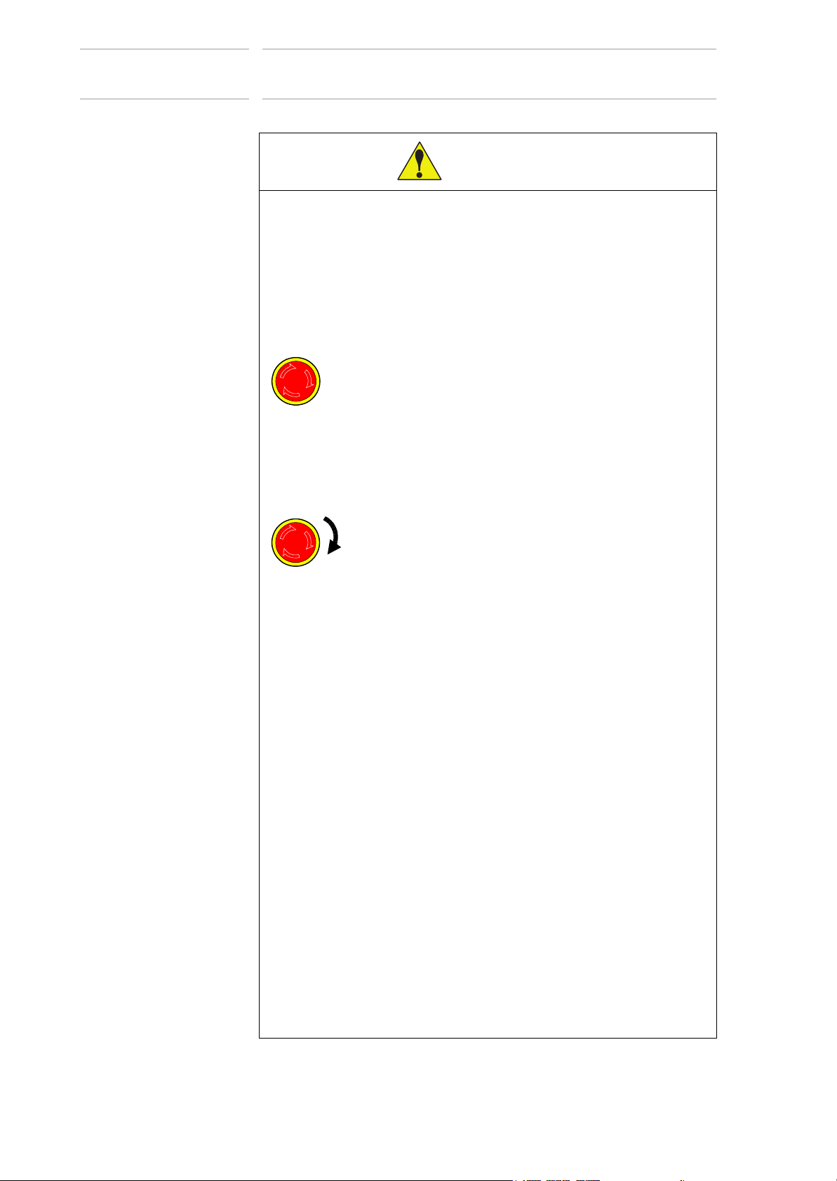
WARNING
• Before operating the manipulator, check that servo power is turned
off when the emergency stop buttons.
When the servo power is turned OFF, the SERVO ON LED on the
programming pendant is turned OFF.
Injury or damage to machinery may result if the emergency stop circuit
cannot stop the manipulator during an emergency. The manipulator
should not be used if the emergency stop buttons do not function.
Fig. : Emergency Stop Button
• Once the emergency stop button is released, clear the cell of all
items which could interfere with the operation of the manipulator.
Then turn ON the servo power.
Injury may result from unintentional or unexpected manipulator motion.
• Observe the following precautions when performing teaching
operations within the P-point maximum envelope of the
manipulator:
-Be sure to use a lockout device to the safeguarding when going
inside. Also, display the sign that the operation is being performed
inside the safeguarding and make sure no one closes the
safeguarding.
- View the manipulator from the front whenever possible.
- Always follow the predetermined operating procedure.
- Keep in mind the emergency response measures against the
manipulator’s unexpected motion toward you.
- Ensure that you have a safe place to retreat in case of emergency.
Improper or unintended manipulator operation may result in injury.
• Confirm that no persons are present in the P-point maximum
envelope of the manipulator and that you are in a safe location
before:
- Turning ON the DX200 power.
- Moving the manipulator with the programming pendant.
- Running check operations.
- Performing automatic operations.
Injury may result if anyone enters the P-point maximum envelope of the
manipulator during operation. Always press an emergency stop button
immediately if there is a problem.
vi
HW1483557
Page 7
175873-1CD
CAUTION
7 of 91
VS100
Definition of Terms Used Often in This Manual
• Perform the following inspection procedures prior to conducting
manipulator teaching. If problems are found, repair them
immediately, and be sure that all other necessary processing has
been performed.
-Check for problems in manipulator movement.
-Check for damage to insulation and sheathing of external wires.
• Always return the programming pendant to the hook on the DX200
cabinet after use.
The programming pendant can be damaged if it is left in the P-point
maximum envelope of the manipulator, on the floor, or near fixtures.
• Read and understand the Explanation of Warning Labels in the
DX200 instructions before operating the manipulator.
Definition of Terms Used Often in This Manual
The MOTOMAN is the YASKAWA industrial robot product.
The MOTOMAN usually consists of the manipulator, the controller, the
programming pendant and supply cables.
In this manual, the equipment is designated as follows:
Equipment Manual Designation
DX200 controller DX200
DX200 programming pendant Programming pendant
Cable between the manipulator and the
controller
Manipulator cable
Description of the Operation Procedure
In the explanation of the operation procedure, the expression “Select • • •”
means that the cursor is moved to the object item and the SELECT key is
pressed, or that the item is directly selected by touching the screen.
Registered Trademark
In this manual, names of companies, corporations, or products are
trademarks, registered trademarks, or brand names for each company or
corporation. The indications of (R) and
vii
TM
are omitted.
HW1483557
Page 8
VS100
8 of 91
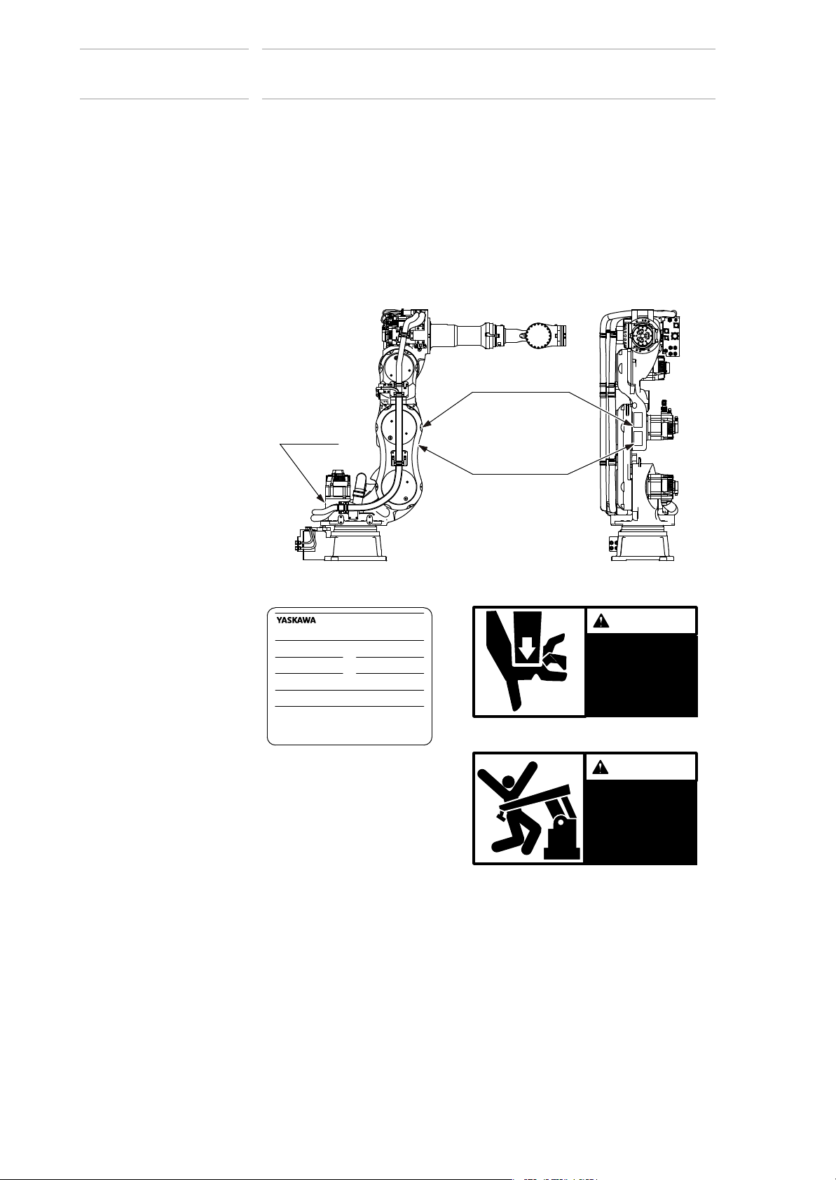
Explanation of Warning Labels
Explanation of Warning Labels
The following warning labels are attached to the manipulator.
Always follow the warnings on the labels.
Also, an identification label with important information is placed on the
body of the manipulator. Prior to operating the manipulator, confirm the
contents.
Fig. : Warning Label Locations
Nameplate
175873-1CD
WARNING Label B
31
WARNING Label A
Nameplate
MODEL
MOTOMANTYPE
PAYLOAD
ORDERNO.
SERIALNO.
YASKAWAELECTRICCORPORATION
2-1Kurosakishiroishi,Yahatanishi-ku,
Kitakyushu806-0004Japan
MADEINJAPAN
MASS
kg
DATE
NJ3878
Warning Label A
WARNING
Moving parts
kg
may cause
injury
Warning Label B
WARNING
Do not enter
robot
work area.
viii
HW1483557
Page 9

175873-1CD
9 of 91
VS100
Safeguarding Tips
All operators, programmers, maintenance personnel, supervisors, and
anyone working near the system must become familiar with the operation
of this equipment. All personnel involved with the operation of the
equipment must understand potential dangers of operation. General
safeguarding tips are as follows:
Safeguarding Tips
• Improper operation can result in personal injury and/or damage to
the equipment. Only trained personnel familiar with the operation of
this equipment, the operator's manuals, the system equipment, and
options and accessories should be permitted to operate this
equipment.
• Improper connections can damage the equipment. All connections
must be made within the standard voltage and current ratings of the
equipment.
• The system must be placed in Emergency Stop (E-Stop) mode
whenever it is not in use.
• In accordance with ANSI/RIA R15.06-2012, section 4.2.5, Sources of
Energy, use lockout/tagout procedures during equipment
maintenance. Refer also to Section 1910.147 (29CFR, Part 1910),
Occupational Safety and Health Standards for General Industry
(OSHA).
Mechanical Safety Devices
The safe operation of this equipment is ultimately the users responsibility.
The conditions under which the equipment will be operated safely should
be reviewed by the user. The user must be aware of the various national
codes, ANSI/RIA R15.06-2012 safety standards, and other local codes
that may pertain to the installation and use of this equipment.
Additional safety measures for personnel and equipment may be required
depending on system installation, operation, and/or location. The following
safety equipment is provided as standard:
• Safety barriers
• Door interlocks
• Emergency stop palm buttons located on operator station
Check all safety equipment frequently for proper operation. Repair or
replace any non-functioning safety equipment immediately.
ix
HW1483557
Page 10

VS100
10 of 91
Programming, Operation, and Maintenance Safety
Programming, Operation, and Maintenance Safety
All operators, programmers, maintenance personnel, supervisors, and
anyone working near the system must become familiar with the operation
of this equipment. Improper operation can result in personal injury and/or
damage to the equipment. Only trained personnel familiar with the
operation, manuals, electrical design, and equipment interconnections of
this equipment should be permitted to program, or maintain the system.
All personnel involved with the operation of the equipment must
understand potential dangers of operation.
• Inspect the equipment to be sure no potentially hazardous conditions
exist. Be sure the area is clean and free of water, oil, debris, etc.
• Be sure that all safeguards are in place. Check all safety equipment
for proper operation. Repair or replace any non-functioning safety
equipment immediately.
• Check the E-Stop button on the operator station for proper operation
before programming. The equipment must be placed in Emergency
Stop (E-Stop) mode whenever it is not in use.
175873-1CD
• Back up all programs and jobs onto suitable media before program
changes are made. To avoid loss of information, programs, or jobs, a
backup must always be made before any service procedures are
done and before any changes are made to options, accessories, or
equipment.
• Any modifications to the controller unit can cause severe personal
injury or death, as well as damage to the robot! Do not make any
modifications to the controller unit. Making any changes without the
written permission from Yaskawa will void the warranty.
• Some operations require a standard passwords and some require
special passwords.
• The equipment allows modifications of the software for maximum
performance. Care must be taken when making these modifications.
All modifications made to the software will change the way the
equipment operates and can cause severe personal injury or death,
as well as damage parts of the system. Double check all
modifications under every mode of operation to ensure that the
changes have not created hazards or dangerous situations.
• This equipment has multiple sources of electrical supply. Electrical
interconnections are made between the controller and other
equipment. Disconnect and lockout/tagout all electrical circuits
before making any modifications or connections.
• Do not perform any maintenance procedures before reading and
understanding the proper procedures in the appropriate manual.
• Use proper replacement parts.
• Improper connections can damage the equipment. All connections
must be made within the standard voltage and current ratings of the
equipment.
x
HW1483557
Page 11

175873-1CD
11 of 91
VS100
Maintenance Safety
Maintenance Safety
Turn the power OFF and disconnect and lockout/tagout all electrical
circuits before making any modifications or connections.
Perform only the maintenance described in this manual. Maintenance
other than specified in this manual should be performed only by Yaskawatrained, qualified personnel.
Summary of Warning Information
This manual is provided to help users establish safe conditions for
operating the equipment. Specific considerations and precautions are also
described in the manual, but appear in the form of Dangers, Warnings,
Cautions, and Notes.
It is important that users operate the equipment in accordance with this
instruction manual and any additional information which may be provided
by Yaskawa. Address any questions regarding the safe and proper
operation of the equipment to Yaskawa Customer Support.
xi
HW1483557
Page 12
VS100
NOTE
(937) 847-3200
12 of 91
Customer Support Information
Customer Support Information
If you need assistance with any aspect of your VS100 system, please
contact Yaskawa Customer Support at the following 24-hour telephone
number:
For routine technical inquiries, you can also contact Yaskawa Customer
Support at the following e-mail address:
When using e-mail to contact Yaskawa Customer Support, please provide
a detailed description of your issue, along with complete contact
information. Please allow approximately 24 to 36 hours for a response to
your inquiry.
175873-1CD
techsupport@motoman.com
Please use e-mail for routine inquiries only. If you have an
urgent or emergency need for service, replacement parts,
or information, you must contact Yaskawa Customer
Support at the telephone number shown above.
Please have the following information ready before you call Customer
Support:
• System VS100
• Primary Application ___________________________
• Controller DX200
• Software Version Access this information on the
Programming Pendant’s LCD
display screen by selecting {MAIN
MENU} - {SYSTEM INFO} {VERSION}
• Robot Serial Number Located on the robot data plate
• Robot Sales Order Number Located on the DX200 controller
data plate
xii
HW1483557
Page 13

175873-1CD
13 of 91
VS100
Table of Contents
Table of Contents
1 Product Confirmation ...................................................................................................................... 1-1
1.1 Contents Confirmation ....................................................................................................... 1-1
1.2 Order Number Confirmation .............................................................................................. 1-2
2 Transport......................................................................................................................................... 2-1
2.1 Transport Method .............................................................................................................. 2-1
2.1.1 Using a Crane ...................................................................................................... 2-2
2.1.2 Using a Forklift...................................................................................................... 2-3
2.2 Shipping Bolts and Brackets.............................................................................................. 2-4
3 Installation....................................................................................................................................... 3-1
3.1 Installation of Safeguarding ............................................................................................... 3-2
3.2 Mounting Procedures for Manipulator Base ...................................................................... 3-2
3.2.1 Mounting the Manipulator on the Baseplate ......................................................... 3-3
3.3 IP (International Protection) ............................................................................................... 3-4
3.4 Location ............................................................................................................................. 3-4
4 Wiring.............................................................................................................................................. 4-1
4.1 Grounding .......................................................................................................................... 4-1
4.2 Cable Connection .............................................................................................................. 4-2
4.2.1 Connection to the Manipulator.............................................................................. 4-2
4.2.2 Connection to the DX200 ..................................................................................... 4-2
5 Basic Specifications ........................................................................................................................ 5-1
5.1 Basic Specifications........................................................................................................... 5-1
5.2 Part Names and Working Axes.......................................................................................... 5-2
5.3 Manipulator Base Dimensions ........................................................................................... 5-2
5.4 Dimensions and P-Point Maximum Envelope.................................................................... 5-3
5.5 Stopping Distance and Time for S-, L-, and E-Axes .......................................................... 5-4
5.5.1 General Information.............................................................................................. 5-4
5.5.2 Definition of Use ................................................................................................... 5-4
5.5.3 Stopping Distance and Time for Stop Category 0: S-, L- and E-Axes.................. 5-4
5.5.4 Stopping Distance and Time for Stop Category 1: S-, L- and E-Axes.................. 5-5
5.5.4.1 Extension ................................................................................................ 5-5
5.5.4.2 Stopping Distance and Time for Stop Category 1: S-Axis....................... 5-7
xiii
HW1483557
Page 14

175873-1CD
14 of 91
VS100
5.5.4.3 Stopping Distance and Time for Stop Category 1: L-Axis .......................5-8
5.5.4.4 Stopping Distance and Time for Stop Category 1: E-Axis....................... 5-9
5.6 Alterable S-Axis Operating Range ................................................................................... 5-10
5.6.1 Necessary Parts ................................................................................................. 5-10
5.6.2 Notes on the S-Axis Mechanical Stopper Installation ......................................... 5-11
5.6.3 Alteration of the S-Axis Pulse Soft Limit ............................................................. 5-12
6 Allowable Load for Wrist Axis and Wrist Flange ............................................................................ 6-1
6.1 Allowable Wrist Load ......................................................................................................... 6-1
6.2 Wrist Flange....................................................................................................................... 6-3
7 System Application.......................................................................................................................... 7-1
7.1 Peripheral Equipment Mounts............................................................................................ 7-1
Table of Contents
7.2 Internal User I/O Wiring Harness and Air Lines for User’s System Applications ...............7-2
8 Electrical Equipment Specification .................................................................................................. 8-1
8.1 Position of Limit Switch ...................................................................................................... 8-1
8.1.1 Specification of Limit Switch ................................................................................. 8-1
8.1.2 Position of Limit Switch......................................................................................... 8-1
8.1.3 Setting of Operation Range .................................................................................. 8-2
8.1.3.1 S-Axis Operation Range.......................................................................... 8-2
8.1.3.2 L-Axis Operation Range .......................................................................... 8-2
8.1.3.3 Setting Range of L- and E-Axes Interference Angle................................ 8-3
8.1.3.4 Setting Range of E- and U-Axes Interference Angle ............................... 8-3
8.2 Internal Connections .......................................................................................................... 8-4
9 Maintenance and Inspection ........................................................................................................... 9-1
9.1 Inspection Schedule........................................................................................................... 9-1
9.2 Battery Pack Replacement ................................................................................................ 9-5
9.3 Grease Replenishment/Exchange ..................................................................................... 9-7
9.3.1 Notes on Grease Replenishment/Exchange Procedures ..................................... 9-7
9.3.2 Grease Replenishment/Exchange for S-Axis Speed Reducer ............................. 9-8
9.3.2.1 Grease Replenishment............................................................................ 9-8
9.3.2.2 Grease Exchange.................................................................................... 9-9
9.3.3 Grease Replenishment/Exchange for L-Axis Speed Reducer............................ 9-10
9.3.3.1 Grease Replenishment.......................................................................... 9-10
9.3.3.2 Grease Exchange.................................................................................. 9-11
9.3.4 Grease Replenishment/Exchange for E-Axis Speed Reducer ........................... 9-12
9.3.4.1 Grease Replenishment.......................................................................... 9-12
xiv
HW1483557
Page 15

175873-1CD
15 of 91
VS100
Table of Contents
9.3.4.2 Grease Exchange ................................................................................. 9-13
9.3.5 Grease Replenishment/Exchange for U-Axis Speed Reducer ........................... 9-14
9.3.5.1 Grease Replenishment.......................................................................... 9-14
9.3.5.2 Grease Exchange ................................................................................. 9-15
9.3.6 Grease Replenishment/Exchange for R-, B-, T- Axes Gears in the Casing
9.3.7 Grease Replenishment/Exchange for B- and T-Axes Speed Reducers
9.4 Notes for Maintenance.....................................................................................................9-22
9.4.1 Battery Pack Connection .................................................................................... 9-22
10 Recommended Spare Parts........................................................................................................ 10-1
11 Parts List ..................................................................................................................................... 11-1
11.1 S-Axis Unit ..................................................................................................................... 11-1
11.2 L-Axis Unit ..................................................................................................................... 11-3
and R-Axis Speed Reducer ................................................................................ 9-16
9.3.6.1 Grease Replenishment for R-, B-, T-Axes Gears in the Casing............ 9-16
9.3.6.2 Grease Replenishment for R-Axis Speed Reducer............................... 9-17
9.3.6.3 Grease Exchange for R-, B-, T-Axes Gears in the Casing.................... 9-18
9.3.6.4 Grease Exchange for R-Axis Speed Reducer....................................... 9-19
and Gears........................................................................................................... 9-20
9.3.7.1 Grease Replenishment.......................................................................... 9-20
9.3.7.2 Grease Exchange ................................................................................. 9-21
11.3 E-Axis Unit ..................................................................................................................... 11-5
11.4 U-Axis Unit..................................................................................................................... 11-7
11.5 R-,B-,T-Axes Unit........................................................................................................... 11-9
11.6 Wrist Unit ..................................................................................................................... 11-12
xv
HW1483557
Page 16

VS100
CAUTION
16 of 91
1 Product Confirmation
1.1 Contents Confirmation
1 Product Confirmation
• Confirm that the manipulator and the DX200 have the same order
number. Special care must be taken when more than one
manipulator is to be installed.
If the numbers do not match, manipulators may not perform as
expected and cause injury or damage.
1.1 Contents Confirmation
Confirm the contents of the delivery when the product arrives.
Standard delivery includes the following four items (Information for the
content of optional goods is given separately):
175873-1CD
• Manipulator
• DX200
• Programming Pendant
• Manipulator cables
1-1
HW1483557
Page 17
175873-1CD
17 of 91
VS100
1 Product Confirmation
1.2 Order Number Confirmation
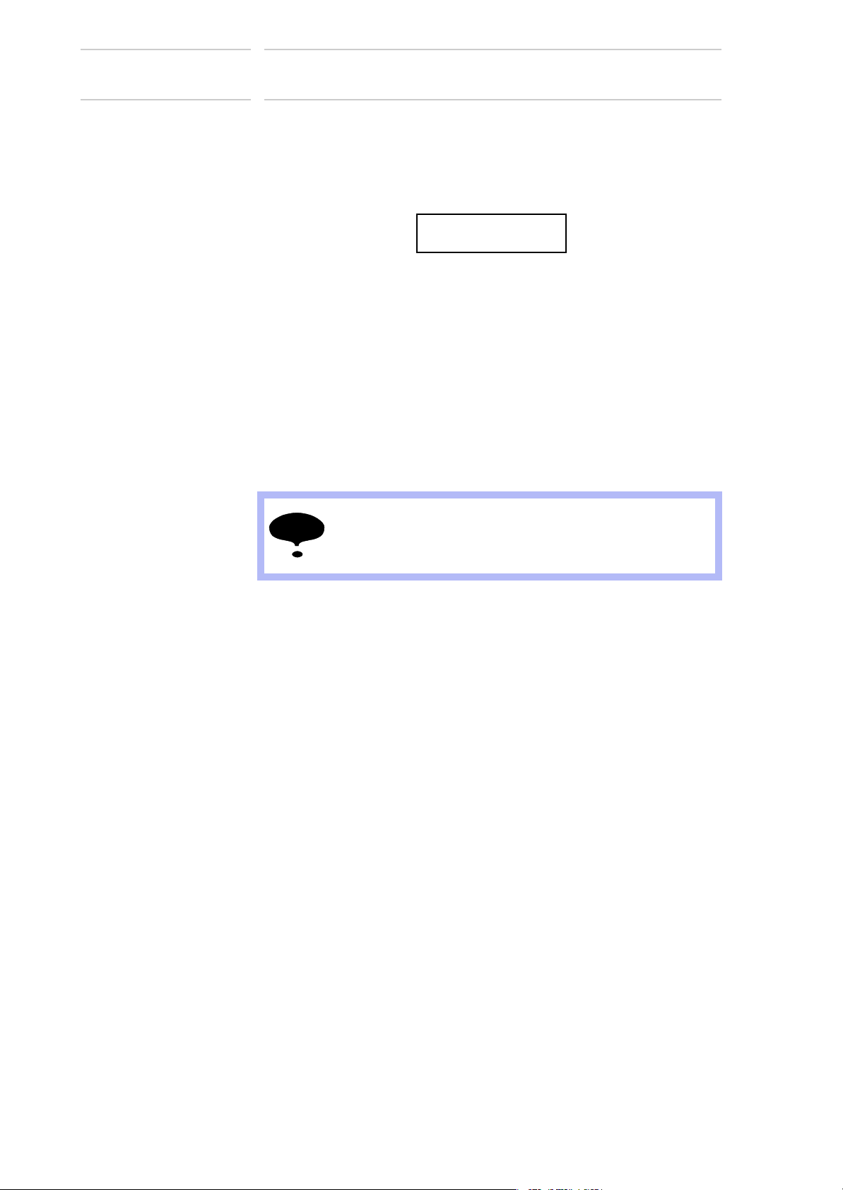
1.2 Order Number Confirmation
Check that the order number of the manipulator corresponds to the
DX200. The order number is indicated on a label as shown below.
Fig. 1-1: Location of Order Number Labels
Label (Enlarged View)
THE MANIPULATOR AND THE CONTROLLER
SHOULD HAVE SAME ORDER NUMBER.
ORDER. No.
Check that the manipulator
and the DX200 have the
same order number.
0
*76$
࣡ࢩࣕ
0
*76$
࣡ࢩࣕ
&'
0;
*76$
࣡ࢩࣕ
(a) DX200 (Front View)
(b) Manipulator (Top View)
1-2
HW1483557
Page 18
VS100
CAUTION
NOTE
18 of 91
2 Transport
175873-1CD
2 Transport
2.1 Transport Method
• Sling and crane or forklift operations must be performed by
authorized personnel only.
Failure to observe this caution may result in injury or damage.
• Avoid excessive vibration or shock during transport.
The system consists of precision components. Failure to observe this
caution may adversely affect performance.
2.1 Transport Method
• Check that the eyebolts are securely fastened.
• The weight of the manipulator is approximately 810kg
including the shipping bolts and brackets. Use a wire rope
strong enough to withstand the weight.
• The attached eyebolts are designed to support the
manipulator mass. Never use them for anything other
than transporting the manipulator.
• Mount the shipping bolts and brackets before transporting
the manipulator.
• Avoid putting external force on the arm of motor unit when
transporting by a crane, forklift, or other equipment.
Failure to observe this instruction may result in injury.
2-1
HW1483557
Page 19
175873-1CD
19 of 91
VS100
2 Transport
2.1 Transport Method
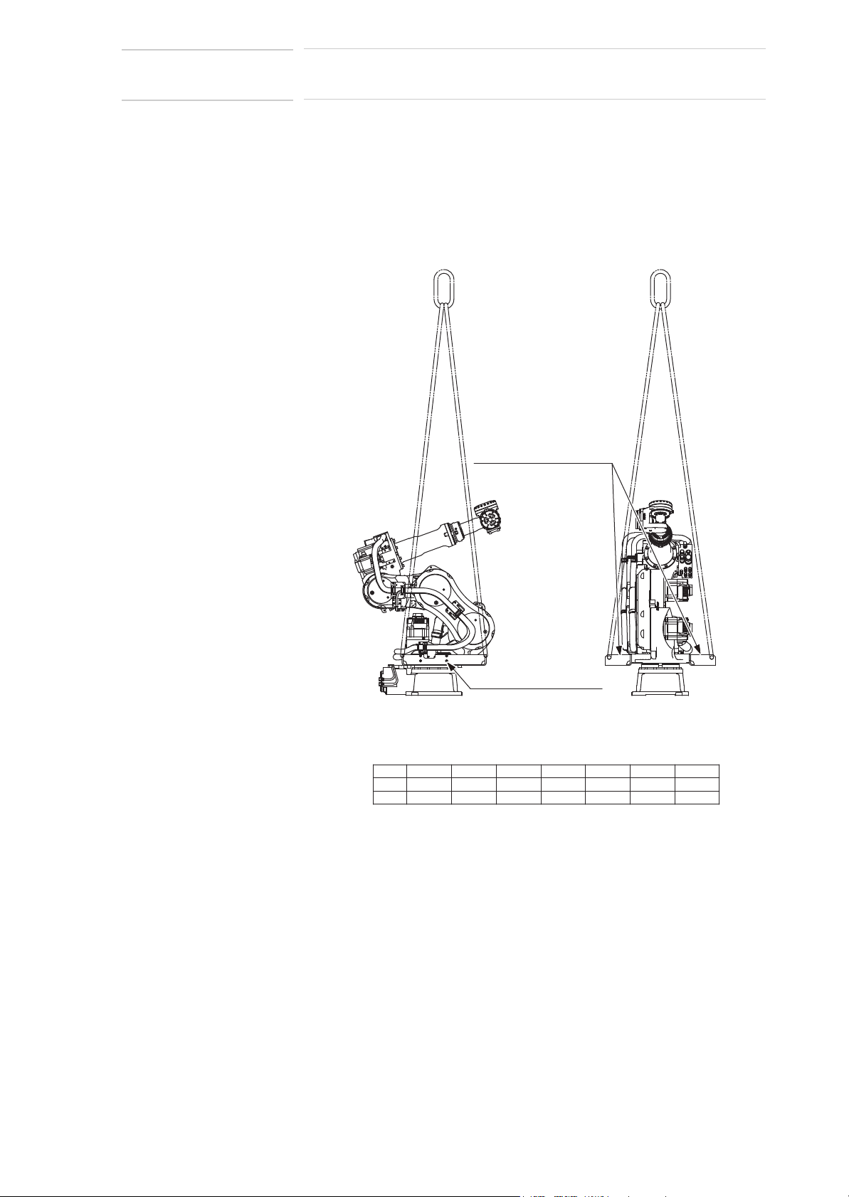
2.1.1 Using a Crane
As a rule, the manipulator should be lifted by a crane with a four-leg bridle
sling using the shipping bolts and brackets when removing it from the
package or moving it. Be sure that the manipulator is fixed with the
shipping bolts and brackets before transport, and lift it in the posture as
shown in Fig. 2-1 “Transport Using a Crane”.
Fig. 2-1: Transport Using a Crane
Shipping bolts and brackets
(Fixed to the manipulator
before shipment.)
Hexagon socket head cap
screw M12 (8 screws)
Factory setting for angle and pulse of each axis
Axis
Angle
Pulse
SLURBT
0㺽
-45㺽 -70㺽 90㺽 -90㺽 0㺽
0
-136192-107008
127377 0-124599
E
-45㺽
-102912
2-2
HW1483557
Page 20

VS100
20 of 91
2 Transport
2.1 Transport Method
2.1.2 Using a Forklift
When using a forklift, the manipulator should be fixed on a pallet with
shipping bolts and brackets as shown in
Insert forks under the pallet and lift it. The pallet must be strong enough to
support the manipulator. Transport the manipulator slowly with due
caution in order to avoid overturning or slippage.
Fig. 2-2: Transport Using a Forklift
Shipping bolts and brackets
(Fixed to the manipulator
before shipment.)
175873-1CD
Fig. 2-2 “Transport Using a Forklift”.
Pallet
Forklift fork entries
Bolt M20 (8 bolts)
2-3
HW1483557
Page 21
175873-1CD
NOTE
21 of 91
VS100
2 Transport
2.2 Shipping Bolts and Brackets
2.2 Shipping Bolts and Brackets
The manipulator is provided with shipping bolts and brackets at positions
shown in Fig. 2-1 “Transport Using a Crane”.
• The shipping bolts and brackets are painted in yellow.
• Refer to the following table for the shipping bolts and brackets fixing
screws.
Table 2-1: Shipping Bolts and Brackets Fixing Screws
Shipping Bolts and
Brackets Qty.
2 Hexagon Socket Head Cap Screw M12
Shipping Bolts and Brackets Fixing
Screw Specification
(length: 25 mm)
(Tensile strength: 1200 N/mm
2
)
Before turning ON the power, check to be sure that the
shipping bolts and brackets are removed. The shipping
bolts and brackets must be stored for future use, in the
event that the manipulator will be moved again.
Fixing Screw
Qty.
4 screws x
2 places
2-4
HW1483557
Page 22

VS100
CAUTION
22 of 91
3 Installation
175873-1CD
3 Installation
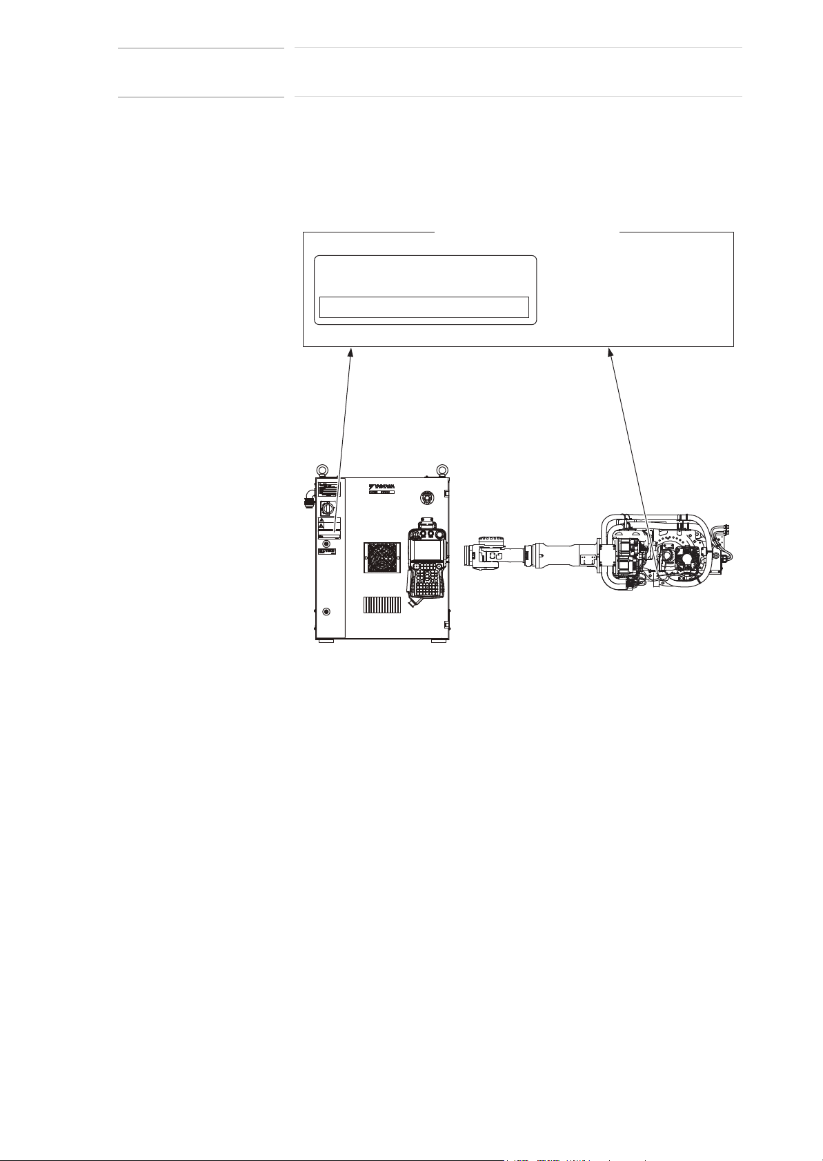
WARNING
• Install the safeguarding.
Failure to observe this warning may result in injury or damage.
• Install the manipulator in a location where the tool or the workpiece
held by its fully extended arm will not reach the wall, safeguarding,
or controller.
Failure to observe this warning may result in injury or damage.
• Do not start the manipulator or even turn ON the power before it is
firmly anchored.
The manipulator may overturn and cause injury or damage.
• Do not install or operate a manipulator that is damaged or lacks
parts.
Failure to observe this caution may cause injury or damage.
• Before turning ON the power, check to be sure that the shipping
bolts and brackets explained in Chapter 2 “Transport” are removed.
Failure to observe this caution may result in damage to the driving
parts.
3-1
HW1483557
Page 23
175873-1CD
23 of 91
VS100
3 Installation
3.1 Installation of Safeguarding
3.1 Installation of Safeguarding
To insure safety, be sure to install the safeguarding. They prevent
unforeseen accidents with personnel and damage to equipment. The
following is quoted for your information and guidance.
Responsibility for Safeguarding (ISO 10218)
The user of a manipulator or robot system shall ensure that safeguarding
is provided and used in accordance with Sections 6, 7, and 8 of this
standard. The means and degree of safeguarding, including any
redundancies, shall correspond directly to the type and level of hazard
presented by the robot system consistent with the robot application.
Safeguarding may include but not be limited to safeguarding devices,
barriers, interlock barriers, perimeter guarding, awareness barriers, and
awareness signals.
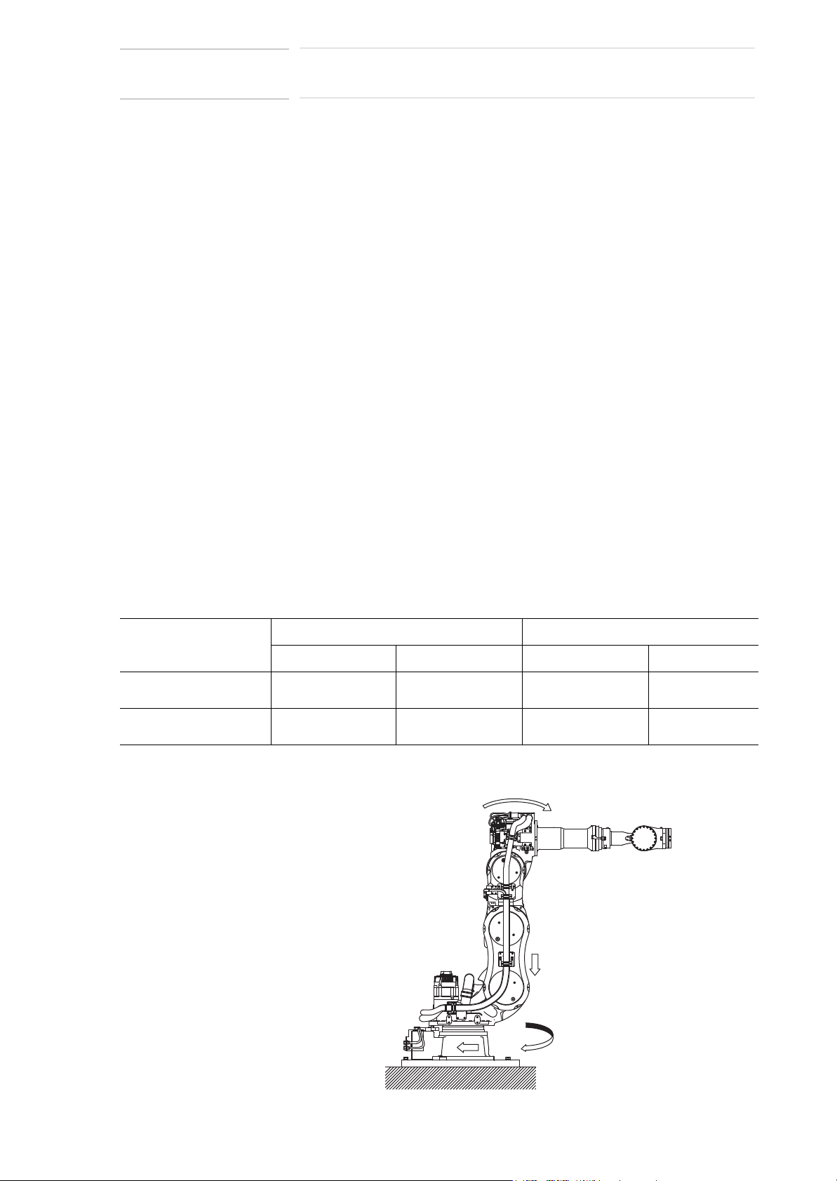
3.2 Mounting Procedures for Manipulator Base
The manipulator should be firmly mounted on a baseplate or foundation
strong enough to support the manipulator and withstand reaction forces
during acceleration and deceleration.
Construct a solid foundation with the appropriate thickness to withstand
maximum reaction forces of the manipulator referring to Table 3-1
“Manipulator Reaction Force and Torque” .
A baseplate flatness must be kept at 0.5 mm or less: insufficient flatness
of installation surface may deform the manipulator shape and affect its
functional abilities. Mount the manipulator base as instructed in section
3.2.1 “Mounting the Manipulator on the Baseplate”.
Table 3-1: Manipulator Reaction Force and Torque
Horizontal rotation Vertical rotation
Reaction force F
Emergency stop 23544 N
(2400 kgf)
Acceleration/deceleration 7358 N
(750 kgf)
Tor q u e M
H
23897 N•m
(2436 kgf•m)
7171 N•m
(731 kgf•m)
Fig. 3-1: Manipulator Reaction Force and Torque
H
Reaction force FVTor q u e M
35316 N
(3600 kgf)
14715 N
(1500 kgf)
0
9
49050 N•m
(5000 kgf•m)
18394 N•m
(1875 kgf•m)
V
3-2
9
)
0
+
)
+
HW1483557
Page 24
VS100
24 of 91
3 Installation
3.2 Mounting Procedures for Manipulator Base
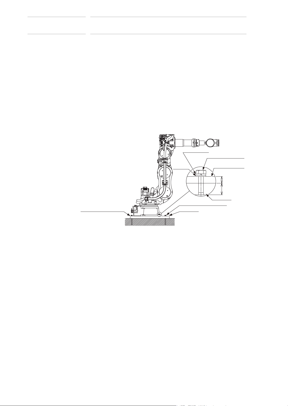
3.2.1 Mounting the Manipulator on the Baseplate
For the first process, anchor the baseplate firmly to the ground. The
baseplate should be rugged and durable to prevent shifting of the
manipulator or the mounting fixture. It is recommend to prepare a
baseplate of 50 mm or thicker, and anchor bolts of M20 or larger size.
The manipulator base is tapped for eight mounting holes; securely fix the
manipulator base to the baseplate with eight hexagon head screws M20
(70 mm long is recommended).
Next, fix the manipulator base to the baseplate. Tighten the hexagon
head bolts and anchor bolts firmly so that they will not work loose during
the operation.
Refer to Fig. 3-2 “Mounting the Manipulator on the Baseplate”.
Fig. 3-2: Mounting the Manipulator on the Baseplate
Spring washer
Washer
175873-1CD
Hexagon head screw
M20 (8 screws)
Manipulator base
Flatness: 0.5mm or less
Anchor bolt (M20 or more)
Baseplate
Baseplate
3-3
HW1483557
Page 25

175873-1CD
25 of 91
VS100
3 Installation
3.3 IP (International Protection)
3.3 IP (International Protection)
For the standard type, environmental resistance for main part of the
manipulator conforms to IP54; the wrist part conforms to IP67.
3.4 Location
When installing a manipulator, it is necessary to satisfy the following
environmental conditions.
• Ambient temperature: 0° to 45°C
• Humidity: 20 to 80%RH (non-condensing)
• Free from exposure to dust, soot, oil, or water.
• Free from corrosive gas or liquid, or explosive gas or liquid
• Free from excessive vibration (Vibration acceleration: 4.9 m/s
[0.5 G] or less)
• Free from large electrical noise (plasma)
2
• Flatness for installation is 0.5 mm or less
3-4
HW1483557
Page 26
VS100
CAUTION
NOTE
26 of 91
4 Wiring
175873-1CD
4 Wiring
4.1 Grounding
WARNING
• Ground resistance must be 100 Ω or less.
Failure to observe this warning may result in fire or electric shock.
• Before wiring, make sure to turn OFF the primary power supply, and
put up a warning sign. (ex. DO NOT TURN THE POWER ON.)
Failure to observe this warning may result in fire or electric shock.
• Wiring must be performed by authorized or certified personnel.
Failure to observe this caution may result in fire or electric shock.
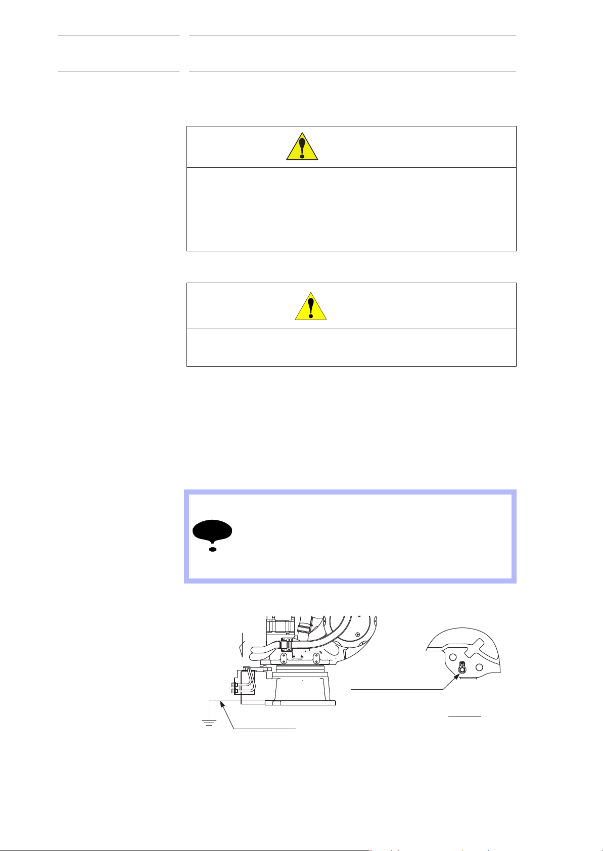
4.1 Grounding
Follow electrical installation standards and wiring regulations for
grounding. A ground wire of 5.5 mm
Refer to Fig. 4-1 “Grounding Method” to connect the ground line directly to
the manipulator.
Fig. 4-1: Grounding Method
2
or more is recommended.
• Never use this wire sharing with other ground lines or
grounding electrodes for other electric power, motor
power, welding devices, etc.
• Where metal ducts, metallic conduits, or distributing racks
are used for cable laying, ground in accordance with
electrical installation standards.
A
5.5mm2 or more
4-1
Bolt M8 (for grounding)
(Delivered with the manipulator)
View A
HW1483557
Page 27

175873-1CD
27 of 91
VS100
4 Wiring
4.2 Cable Connection
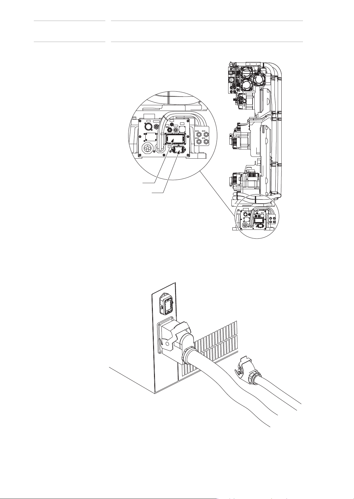
4.2 Cable Connection
Two manipulator cables are delivered with the manipulator: an encoder
cable (1BC) and a power cable (2BC). (Refer to Fig. 4-2 “Manipulator
Cables”.)
Connect these cables to the connectors on the manipulator connector
base and the DX200 board connectors. Refer to Fig. 4-3(a) “Manipulator
Cable Connection (Manipulator Side)” and Fig. 4-3(b) “Manipulator Cable
Connection (DX200 Side)”.
4.2.1 Connection to the Manipulator
Before connecting two cables to the manipulator, verify the numbers on
both manipulator cables and the connectors on the connector base of the
manipulator. When connecting, adjust the cable connector positions to
the main key positions of the manipulator, and insert cables in the order of
2BC, then 1BC. After inserting the cables, depress the lever until it clicks.
4.2.2 Connection to the DX200
Before connecting cables to the DX200, verify the numbers on both
manipulator cables and the connectors on the DX200. When connecting,
insert the cables in the order of X21, then X11, and depress each lever
until it clicks.
Fig. 4-2: Manipulator Cables
The DX200 Side
X11
X11
The DX200 Side
X21
The Manipulator Side
1BC
1BC
1BC
Encoder Cable
The Manipulator Side
2BC
4-2
2BC
Power Cable
HW1483557
Page 28
VS100
28 of 91
4 Wiring
4.2 Cable Connection
Fig. 4-3(a): Manipulator Cable Connection (Manipulator Side)
'&3:
%&
'1(7
)%7
0RO\:KLWH
5(1R
*UHDVH
$,5
,1
%&
%&
:75$,5
:75$,5 :75$,5
:75$,5
0
*76$
0
*76$
6
%&
࣡ࢩࣕ
*76$
࣡ࢩࣕ
0
*76$
0
࣡ࢩࣕ
*76$
*76$
0
0
&'
*76$
0
&'
࣡ࢩࣕ
*76$
0;
࣡ࢩࣕ
*76$
0
*76$
0
*76$
0
&'
࣡ࢩࣕ
࣡ࢩࣕ
*76$
࣡ࢩࣕ
0;
*76$
0
࣡ࢩࣕ
*76$
0;
࣡ࢩࣕ
*76$
0
࣡ࢩࣕ
*76$
0
175873-1CD
&'
&'
&'
6
'&3:
Fig. 4-3(b): Manipulator Cable Connection (DX200 Side)
X11
X21
0RO\:KLWH
5(1R
*UHDVH
,1
%&
'1(7
)%7
$,5
%&
4-3
HW1483557
Page 29

175873-1CD
29 of 91
VS100
5 Basic Specifications
5.1 Basic Specifications
5 Basic Specifications
5.1 Basic Specifications
Table 5-1: Basic Specifications
Item Model MOTOMAN-VS100
YASKAWA Standard External Cable
Structure Vertically Articulated
Degree of Freedom 7
Payload 110 kg 100 kg
Repeatability
Range of Motion S-Axis (turning) -180° - +180°
Maximum Speed S-Axis 2.45 rad/s, 140°/s
Allowable Moment
Allowable Inertia
2
/4)
(GD
Approx. Mass 780 kg
Protective Structure Basic axis: IP54 or equivalent
Ambient Conditions Temperature 0° C to 45° C
Power Requirements 5.5 kVA
Noise
1 SI units are used in this table. However, gravitational unit is used in ( ).
2 Specification changes when the manipulator is equipped with YASKAWA standard external cable.
3 Conformed to ISO9283
4 Refer to section 6.1 “Allowable Wrist Load” for details on the permissible moment of inertia.
5 Conformed to ISO6926
1, Measurement is carried out when the maximum load is mounted to the manipulator and
operated in the maximum speed.
2, Measurement is carried out:
- between 1.2m and 1.5m above the ground.
- 400mm away from the P-point maximum envelope.
3)
L-Axis (lower arm) -45° - +155°
E-Axis (elbow) -45° - +120°
U-Axis (upper arm) -70° - +90°
R-Axis (wrist roll) -360° - +360° -205° - +205°
B-Axis (wrist pitch/yaw) -125° - +125° -120° - +120°
T-Axis (wrist twist) -360° - +360° -205° - +205°
L-Axis 1.92 rad/s, 110°/s
E-Axis 1.92 rad/s, 110°/s
U-Axis 2.27 rad/s, 130°/s
R-Axis 3.05 rad/s, 175°/s
B-Axis 3.05 rad/s, 175°/s
T-Axis 4.45 rad/s, 255°/s
4)
R-Axis 721 N•m (73.5 kgf•m) 696 N•m (71 kgf•m)
B-Axis 721 N•m (73.5 kgf•m) 696 N•m (71 kgf•m)
T-Axis 294 N•m (30 kgf•m)
R-Axis 60 kg•m
B-Axis 60 kg•m
T-Axis 33.7 kg•m
Humidity 20 to 80% RH (non-condensing)
Vibration Acceleration 4.9 m/s
Others Free from corrosive gasses or liquids, or explosive gasses
5)
1)
2)
Not Equipped Equipped
±0.12 mm
2
2
2
Wrist axis only: IP67 or equivalent
2
or less (0.5 G)
Free from exposure to water, oil, or dust
Free from excessive electrical noise (plasma)
75 dB
58 kg•m
58 kg•m
33 kg•m
2
2
2
5-1
HW1483557
Page 30

VS100
30 of 91
5 Basic Specifications
5.2 Part Names and Working Axes
5.2 Part Names and Working Axes
Fig. 5-1: Part Names and Working Axes
Middle arm
(L-armB)
E-
Rotary head
(S-head )
U+
U-
E+
/L-
Lower arm
(L-arm A)
R+
R-
Upper arm
(U-arm)
B+
B-
Wrist flange
T+
T-
Wrist
175873-1CD
R+R-
T-
T+
Base
S+
S-
5.3 Manipulator Base Dimensions
Fig. 5-2: Manipulator Base Dimensions
455
30
A
195±0.2
230±0.2
385
320
195±0.2
153 455
12 dia. hole
(2 holes )
280
400
608
22dia. hole (8 holes)
+0.018
0
230
195±0.2
230±0.2195±0.2
S+S-
5-2
View A
HW1483557
Page 31

175873-1CD
31 of 91
VS100
5 Basic Specifications
5.4 Dimensions and P-Point Maximum Envelope
5.4 Dimensions and P-Point Maximum Envelope
Fig. 5-3: Dimensions and P-Point Maximum Envelope
320 1020 200
R2236
P-point
Maximum envelope
613
45°
70°
45°
90°
540 435 435 235
316
685
1469 2236
0
31
3705
155°
P-point
270
24571336
258
3793
314 258
584
5-3
HW1483557
Page 32

VS100
32 of 91
175873-1CD
5 Basic Specifications
5.5 Stopping Distance and Time for S-, L-, and E-Axes
5.5 Stopping Distance and Time for S-, L-, and E-Axes
5.5.1 General Information
• The stopping distance is an angle traveled by the manipulator from
the moment when the stop signal is activated until the manipulator
comes to a complete standstill.
• The stopping time is a time elapsed from the moment that the stop
signal is activated until the manipulator comes to a complete
standstill.
• The data that are given for the main axes S, L and E are the
maximum displacement.
• Superposed axes motions may result in longer stopping distance.
• Stopping distance and stopping time are measured in accordance
with ISO 10218-1, Annex B.
• Stop categories: According to IEC60204-1
• Stop category 0
• Stop category 1
• The values specified for Stop category 0 are the reference values
that are determined by tests and simulations. The actual stopping
distance and stopping time may differ.
• The stopping distance and stopping time are measured using the
manipulator-internal measuring technique.
5.5.2 Definition of Use
Load : Rated load weight and load on an arm
Speed : Operating speed of the manipulator
Extension : Distance between the rotation center and the P-point of
each axis
5.5.3 Stopping Distance and Time for Stop Category 0: S-, L- and E-Axes
Measurement Conditions
• Load: Maximum load
• Speed: Maximum speed
• Posture: Maximum inertia generating posture
Axis Stopping distance (deg) Stopping Time (sec)
S-axis 31.7 0.669
L-axis 25.5 0.451
E-axis 20.9 0.388
5-4
HW1483557
Page 33

175873-1CD
33 of 91
VS100
5 Basic Specifications
5.5 Stopping Distance and Time for S-, L-, and E-Axes
5.5.4 Stopping Distance and Time for Stop Category 1: S-, L- and E-Axes
5.5.4.1 Extension
Refer to Fig. 5-4 “S-Axis Extension”, Fig. 5-5 “L-Axis Extension” and
Fig. 5-6 “E-Axis Extension”for each axis arm extension.
Fig. 5-4: S-Axis Extension
100%=2236
66%
Fig. 5-5: L-Axis Extension
33%
100%=1917
66%
5-5
33%
HW1483557
Page 34

VS100
34 of 91
175873-1CD
5 Basic Specifications
5.5 Stopping Distance and Time for S-, L-, and E-Axes
Fig. 5-6: E-Axis Extension
100%=1482
66%
5-6
HW1483557
Page 35

175873-1CD
35 of 91
VS100
5 Basic Specifications
5.5 Stopping Distance and Time for S-, L-, and E-Axes
5.5.4.2 Stopping Distance and Time for Stop Category 1: S-Axis
㻢㻜
㻡㻜
㻠㻜
㻟㻜
㻞㻜
㻿㼠㼛㼜㼜㼕㼚㼓㻌㼐㼕㼟㼠㼍㼚㼏㼑㼇㼐㼑㼓㼉
㻝㻜
㻜
㻜 㻟㻜 㻢㻜 㻥㻜 㻝㻞㻜 㻝㻡㻜
㻸㼛㼍㼐㻝㻜㻜㻑 㻸㼛㼍㼐㻢㻢㻑 㻸㼛㼍㼐㻟㻟㻑
Extension 100% Extension 100%
㻿㼜㼑㼑㼐㼇㼐㼑㼓㻛㼟㼉
Extension 66%
㻢㻜
㻡㻜
㻠㻜
㻟㻜
㻞㻜
㻿㼠㼛㼜㼜㼕㼚㼓㻌㼐㼕㼟㼠㼍㼚㼏㼑㼇㼐㼑㼓㼉
㻝㻜
㻜
㻜 㻟㻜 㻢㻜 㻥㻜 㻝㻞㻜 㻝㻡㻜
㻸㼛㼍㼐㻝㻜㻜㻑 㻸㼛㼍㼐㻢㻢㻑 㻸㼛㼍㼐㻟㻟㻑
㻿㼜㼑㼑㼐㼇㼐㼑㼓㻛㼟㼉
㻝㻚㻜
㻜㻚㻤
㻜㻚㻢
㻜㻚㻠
㻿㼠㼛㼜㼜㼕㼚㼓㻌㼠㼕㼙㼑㼇㼟㼑㼏㼉
㻜㻚㻞
㻜㻚㻜
㻜 㻟㻜 㻢㻜 㻥㻜 㻝㻞㻜 㻝㻡㻜
㻸㼛㼍㼐㻝㻜㻜㻑 㻸㼛㼍㼐㻢㻢㻑 㻸㼛㼍㼐㻟㻟㻑
㻝㻚㻜
㻜㻚㻤
㻜㻚㻢
㻜㻚㻠
㻿㼠㼛㼜㼜㼕㼚㼓㻌㼠㼕㼙㼑㼇㼟㼑㼏㼉
㻜㻚㻞
㻜㻚㻜
㻜 㻟㻜 㻢㻜 㻥㻜 㻝㻞㻜 㻝㻡㻜
㻸㼛㼍㼐㻝㻜㻜㻑 㻸㼛㼍㼐㻢㻢㻑 㻸㼛㼍㼐㻟㻟㻑
㻿㼜㼑㼑㼐㼇㼐㼑㼓㻛㼟㼉
Extension 66%
㻿㼜㼑㼑㼐㼇㼐㼑㼓㻛㼟㼉
㻡㻜
Extension 33%
㻠㻜
㻟㻜
㻞㻜
㻝㻜
㻿㼠㼛㼜㼜㼕㼚㼓㻌㼐㼕㼟㼠㼍㼚㼏㼑㼇㼐㼑㼓㼉
㻜
㻜 㻟㻜 㻢㻜 㻥㻜 㻝㻞㻜 㻝㻡㻜
㻸㼛㼍㼐㻝㻜㻜㻑 㻸㼛㼍㼐㻢㻢㻑
㻿㼜㼑㼑㼐㼇㼐㼑㼓㻛㼟㼉
㻸㼛㼍㼐㻟㻟㻑
㻜㻚㻡
㻜㻚㻠
㻜㻚㻟
㻜㻚㻞
㻿㼠㼛㼜㼜㼕㼚㼓㻌㼠㼕㼙㼑㼇㼟㼑㼏㼉
㻜㻚㻝
㻜㻚㻜
㻜 㻟㻜 㻢㻜 㻥㻜 㻝㻞㻜 㻝㻡㻜
㻸㼛㼍㼐㻝㻜㻜㻑 㻸㼛㼍㼐㻢㻢㻑
Extension 33%
㻿㼜㼑㼑㼐㼇㼐㼑㼓㻛㼟㼉
㻸㼛㼍㼐㻟㻟㻑
5-7
HW1483557
Page 36

VS100
㻜
㻡
㻝㻜
㻝㻡
㻟㻜
㻞㻡
㻞㻜
Extension 33% Extension 33%
㻿㼠㼛㼜㼜㼕㼚㼓㻌㼐㼕㼟㼠㼍㼚㼏㼑㼇㼐㼑㼓㼉
㻜 㻞㻜 㻢㻜 㻤㻜 㻝㻞㻜㻠㻜 㻝㻜㻜
㻿㼜㼑㼑㼐㼇㼐㼑㼓㻛㼟㼉
㻿㼜㼑㼑㼐㼇㼐㼑㼓㻛㼟㼉
㻜 㻞㻜 㻢㻜 㻤㻜 㻝㻞㻜㻠㻜 㻝㻜㻜
㻸㼛㼍㼐㻝㻜㻜㻑 㻸㼛㼍㼐㻢㻢㻑 㻸㼛㼍㼐㻟㻟㻑 㻸㼛㼍㼐㻝㻜㻜㻑 㻸㼛㼍㼐㻢㻢㻑 㻸㼛㼍㼐㻟㻟㻑
㻜㻚㻜
㻜㻚㻝
㻜㻚㻞
㻜㻚㻠
㻿㼠㼛㼜㼜㼕㼚㼓㻌㼠㼕㼙㼑㼇㼟㼑㼏㼉
㻜㻚㻟
㻜㻚㻡
36 of 91
175873-1CD
5 Basic Specifications
5.5 Stopping Distance and Time for S-, L-, and E-Axes
5.5.4.3 Stopping Distance and Time for Stop Category 1: L-Axis
㻟㻡
㻟㻜
㻞㻡
㻞㻜
㻝㻡
㻝㻜
㻿㼠㼛㼜㼜㼕㼚㼓㻌㼐㼕㼟㼠㼍㼚㼏㼑㼇㼐㼑㼓㼉
㻡
㻜
㻜 㻞㻜 㻢㻜 㻤㻜 㻝㻞㻜㻠㻜 㻝㻜㻜 㻜 㻞㻜 㻢㻜 㻤㻜 㻝㻞㻜㻠㻜 㻝㻜㻜
㻸㼛㼍㼐㻝㻜㻜㻑 㻸㼛㼍㼐㻢㻢㻑 㻸㼛㼍㼐㻟㻟㻑
㻟㻡
㻟㻜
㻞㻡
㻞㻜
㻝㻡
㻝㻜
㻿㼠㼛㼜㼜㼕㼚㼓㻌㼐㼕㼟㼠㼍㼚㼏㼑㼇㼐㼑㼓㼉
㻡
㻜
㻜 㻞㻜 㻢㻜 㻤㻜 㻝㻞㻜㻠㻜 㻝㻜㻜
㻸㼛㼍㼐㻝㻜㻜㻑 㻸㼛㼍㼐㻢㻢㻑 㻸㼛㼍㼐㻟㻟㻑
Extension 100% Extension 100%
㻿㼜㼑㼑㼐㼇㼐㼑㼓㻛㼟㼉
Extension 66%
㻿㼜㼑㼑㼐㼇㼐㼑㼓㻛㼟㼉
㻜㻚㻢
㻜㻚㻡
㻜㻚㻠
㻜㻚㻟
㻜㻚㻞
㻿㼠㼛㼜㼜㼕㼚㼓㻌㼠㼕㼙㼑㼇㼟㼑㼏㼉
㻜㻚㻝
㻜㻚㻜
㻿㼜㼑㼑㼐㼇㼐㼑㼓㻛㼟㼉
㻸㼛㼍㼐㻝㻜㻜㻑 㻸㼛㼍㼐㻢㻢㻑 㻸㼛㼍㼐㻟㻟㻑
㻜㻚㻢
㻜㻚㻡
㻜㻚㻠
㻜㻚㻟
㻜㻚㻞
㻿㼠㼛㼜㼜㼕㼚㼓㻌㼠㼕㼙㼑㼇㼟㼑㼏㼉
㻜㻚㻝
㻜㻚㻜
㻜 㻞㻜 㻢㻜 㻤㻜 㻝㻞㻜㻠㻜 㻝㻜㻜
㻸㼛㼍㼐㻝㻜㻜㻑 㻸㼛㼍㼐㻢㻢㻑 㻸㼛㼍㼐㻟㻟㻑
Extension 66%
㻿㼜㼑㼑㼐㼇㼐㼑㼓㻛㼟㼉
5-8
HW1483557
Page 37

175873-1CD
37 of 91
VS100
5 Basic Specifications
5.5 Stopping Distance and Time for S-, L-, and E-Axes
5.5.4.4 Stopping Distance and Time for Stop Category 1: E-Axis
㻟㻡
㻟㻜
㻞㻡
㻞㻜
㻝㻡
㻝㻜
㻿㼠㼛㼜㼜㼕㼚㼓㻌㼐㼕㼟㼠㼍㼚㼏㼑㼇㼐㼑㼓㼉
㻡
㻜
㻜 㻞㻜 㻢㻜 㻤㻜 㻝㻞㻜㻠㻜 㻝㻜㻜
㻸㼛㼍㼐㻝㻜㻜㻑 㻸㼛㼍㼐㻢㻢㻑 㻸㼛㼍㼐㻟㻟㻑
Extension 100% Extension 100%
㻿㼜㼑㼑㼐㼇㼐㼑㼓㻛㼟㼉
Extension 66% Extension 66%
㻟㻜
㻞㻡
㻞㻜
㻝㻡
㻝㻜
㻿㼠㼛㼜㼜㼕㼚㼓㻌㼐㼕㼟㼠㼍㼚㼏㼑㼇㼐㼑㼓㼉
㻡
㻜
㻜 㻞㻜 㻢㻜 㻤㻜 㻝㻞㻜㻠㻜 㻝㻜㻜
㻸㼛㼍㼐㻝㻜㻜㻑 㻸㼛㼍㼐㻢㻢㻑 㻸㼛㼍㼐㻟㻟㻑
㻿㼜㼑㼑㼐㼇㼐㼑㼓㻛㼟㼉
㻜㻚㻢
㻜㻚㻡
㻜㻚㻠
㻜㻚㻟
㻜㻚㻞
㻿㼠㼛㼜㼜㼕㼚㼓㻌㼠㼕㼙㼑㼇㼟㼑㼏㼉
㻜㻚㻝
㻜㻚㻜
㻜 㻞㻜 㻢㻜 㻤㻜 㻝㻞㻜㻠㻜 㻝㻜㻜
㻸㼛㼍㼐㻝㻜㻜㻑 㻸㼛㼍㼐㻢㻢㻑 㻸㼛㼍㼐㻟㻟㻑
㻜㻚㻢
㻜㻚㻡
㻜㻚㻠
㻜㻚㻟
㻜㻚㻞
㻿㼠㼛㼜㼜㼕㼚㼓㻌㼠㼕㼙㼑㼇㼟㼑㼏㼉
㻜㻚㻝
㻜㻚㻜
㻜 㻞㻜 㻢㻜 㻤㻜 㻝㻞㻜㻠㻜 㻝㻜㻜
㻸㼛㼍㼐㻝㻜㻜㻑 㻸㼛㼍㼐㻢㻢㻑 㻸㼛㼍㼐㻟㻟㻑
㻿㼜㼑㼑㼐㼇㼐㼑㼓㻛㼟㼉
㻿㼜㼑㼑㼐㼇㼐㼑㼓㻛㼟㼉
5-9
HW1483557
Page 38

VS100
38 of 91
5 Basic Specifications
5.6 Alterable S-Axis Operating Range
5.6 Alterable S-Axis Operating Range
The operating range of the S-axis can be altered in accordance with the
operating conditions as shown in Fig. 5-2 “S-Axis Operating Range”. If
alteration is necessary, contact your YASKAWA representative in
advance.
Table 5-2: S-Axis Operating Range
Item Specifications
S-Axis Operating Range -180° - +180°
-165° - +165°
-150° - +150°
-135° - +135°
-120° - +120°
-105° - +105°
-90° - +90°
-75° - +75°
-60° - +60°
-45° - +45°
-30° - +30°
-15° - +15°
175873-1CD
(standard)
5.6.1 Necessary Parts
When altering the operating range of the S-axis, following parts shown in
Fig. 5-7 “S-Axis Mechanical Stopper” are necessary in addition to the
already delivered parts.
(1) Hexagon socket head cap screw M20 (length: 40 mm)
(Tensile strength: 1200N/mm
stopper)
(2) Collar (drawing No. HW9405875-1) x 1
(3) Pin (drawing No. HW9405032-2) x 1
(Necessary only when the manipulator is equipped with the S-axis
overrun limit switch.)
Fig. 5-7: S-Axis Mechanical Stopper
2
) x 1 screw (for the mechanical
Collar
HW9405875-1
Hexagon socket head cap screw
M20 (length: 40 mm)
(as a mechanical stopper)
Pin (HW9405032-2)
(Necessary only when the manipulator is
equipped with the S-axis overrun limit switch)
5-10
HW1483557
Page 39

175873-1CD
39 of 91
VS100
5 Basic Specifications
5.6 Alterable S-Axis Operating Range
5.6.2 Notes on the S-Axis Mechanical Stopper Installation
Mount the collar (drawing No. HW9405875-1) to the hexagon socket head
screws M20 (length: 40 mm) (Tensile strength: 1200N/mm
2
). Then, as
shown in Fig. 5-7 “S-Axis Mechanical Stopper”, mount the S-axis
mechanical stopper to the S-head using the collar with the screws with the
tightening torque of 167 N•m (17 kgf•m).
The S-axis mechanical stopper can be mounted in every 15-degree pitch
as shown in Fig. 5-8 “S-Axis Stopper Mounting Position”.
When the manipulator is equipped with the S-axis overrun limit switches,
install the pins (drawing No. HW9405032-2) to the same degree positions
as the hexagon socket head cap screw.
Fig. 5-8: S-Axis Stopper Mounting Position
Section A-A
AA
5-11
HW1483557
Page 40

VS100
NOTE
40 of 91
5 Basic Specifications
5.6 Alterable S-Axis Operating Range
5.6.3 Alteration of the S-Axis Pulse Soft Limit
When limiting the S-axis range of motion, alter the parameter from the
programming pendant by referring to the DX200 INSTRUCTIONS.
Pulse limit (positive (+) direction of the S-axis): S1CxG400
Pulse limit (negative (-) direction of the S-axis): S1CxG408
Degree 0° -15°− +15° -30°− +30° -45°− +45° -60° − +60°
Pulse 0 -21203
-
+21203
D e g r e e -75°− +75° -90°− +90° -105°− +105° -120°− +120° -135° − +135°
Pulse -106015
-
+106015
-127217
-
+127217
-42406
+42406
-148420
-
+148420
175873-1CD
-63609
-
-
+63609
-169623
-
+169623
-84812
-
+84812
-190826
-
+190826
Degree -150°− +150° -165°− +165° -180° − +180° (Standard)
Pulse -212029
-
+212029
-233232
-
+233232
-254434
-
+254434
Please do not alter the range of motion with the software
only, but in combination with the mechanical stopper.
Also, when executing the alteration, be sure to uniform the
range.
5-12
HW1483557
Page 41

175873-1CD
41 of 91
VS100
6 Allowable Load for Wrist Axis and Wrist Flange
6.1 Allowable Wrist Load
6 Allowable Load for Wrist Axis and Wrist Flange
6.1 Allowable Wrist Load
The allowable wrist load including the weight of the mount/gripper is as
follows at each specification.
: 110 kg maximum (without YASKAWA standard external cable)
: 100 kg maximum (with YASKAWA standard external cable)
If force is applied to the wrist instead of the load, force on R-, B-, and Taxes should be within the value shown in
Load (without YASKAWA standard external cable)”and Table 6-1(b)
“Allowable Wrist Load (with YASKAWA standard external cable)”.
your YASKAWA representative for further information or assistance.
Table 6-1(a): Allowable Wrist Load (without YASKAWA standard external
cable)
Axis Moment N•m (kgf•m)
R-Axis 721 (73.5) 60
B-Axis 721 (73.5) 60
T-Axis 294 (30) 33.7
1 ( ): Gravitational unit
1)
Table 6-1(a) “Allowable Wrist
2
/4 Total Moment of Inertia kg•m
GD
Contact
2
Table 6-1(b): Allowable Wrist Load (with YASKAWA standard external
cable)
Axis Moment N•m (kgf•m)
R-Axis 696 (71) 58
B-Axis 696 (71) 58
T-Axis 294 (30) 33
1 ( ): Gravitational unit
1)
2
/4 Total Moment of Inertia kg•m
GD
2
When the volume load is small, refer to the moment arm rating shown in
Fig. 6-1 “Moment Arm Rating”.
The allowable total moment of inertia is calculated when the moment is at
the maximum. Contact your YASKAWA representative beforehand when
only moment of inertia, or load moment is small and moment of inertia is
large. Also, when the load mass is combined with an outside force,
contact your YASKAWA representative beforehand.
6-1
HW1483557
Page 42

VS100
42 of 91
175873-1CD
6 Allowable Load for Wrist Axis and Wrist Flange
6.1 Allowable Wrist Load
Fig. 6-1: Moment Arm Rating
Without YASKAWA standard external cable
P-point
LT(mm)
600
400
200
200
400
600
LT(mm)
50kg
60kg
80kg
110kg
800
600
400
B-axis center of rotation
1000
With YASKAWA standard external cable
P-point
LT(mm)
600
400
200
50kg
60kg
80kg
100kg
400
600
800
1000
1200
1200
1400
1400
R-, T-axis
center of rotation
LB(mm)
1600
R-, T
center of rotation
LB(mm)
1600
-axis
200
400
600
LT(mm)
B-axis center of rotation
6-2
HW1483557
Page 43

175873-1CD
NOTE
43 of 91
VS100
6 Allowable Load for Wrist Axis and Wrist Flange
6.2 Wrist Flange
6.2 Wrist Flange
The wrist flange dimensions are shown in Fig. 6-2 “Wrist Flange (without
YASKAWA standard external cable)”. To make the alignment mark visible
and to enable an easy grease exchange for the B- and T-axis gears,
mount the attachment inside the fitting. Fitting depth of inside and outside
fittings must be 5 mm or less.
Fig. 6-2: Wrist Flange (without YASKAWA standard external cable)
+0.025
125
Tapped hole M10
(depth: 15.0)(10 holes)
+0.015
10 dia.
0
0
0
-0.025
(depth: 15.0) (2 holes)
145 dia.
31.5 dia.
Wash off anti-corrosive paint (yellow) on the wrist flange
surface with thinner or light oil before mounting the tools.
6-3
HW1483557
Page 44

VS100
44 of 91
7 System Application
7.1 Peripheral Equipment Mounts
7 System Application
7.1 Peripheral Equipment Mounts
The peripheral equipment mounts are provided on the U-axis (upper arm)
as shown in Fig. 7-1 “Installing Peripheral Equipment” for easier
installation of the user’s system applications. The following conditions
shall be observed to attach or install peripheral equipment.
Fig. 7-1: Installing Peripheral Equipment
175873-1CD
Tapped hole M6(depth:11)
(2 holes)
82
45
Tapped hole M8(depth:14)
(4 holes)
Tapped hole M5(depth:9)
(2 holes)
191
27.5 12.5
110 110
16
60
16
246
60180
Tapped hole M8(depth:16)
(4 holes)
50 50
Mount the peripheral equipment
within this range.
98.5100
Table 7-1: Constraint for Attaching
Application Note
Cable processing
and valve, etc mounting
Up to 10 kg.
49 N•m (5 kgf•m) max. for increased moment
amount of upper arm
7-1
HW1483557
Page 45

175873-1CD
45 of 91
VS100
7 System Application
7.2 Internal User I/O Wiring Harness and Air Lines for User’s System Applications
7.2 Internal User I/O Wiring Harness and Air Lines for User’s
System Applications
Internal user I/O wiring harness, encoder and power cables for external
axis, cables for primary source for welding, D-NET cables, cables for
+24V and hoses for air or cooling are incorporated in the manipulator for
the drive of peripheral devices mounted on the upper arm as shown in Fig.
7-2 “Connectors for Internal User I/O Wiring Harness and Air Lines for
User’s Applications”and Fig. 7-3 “Details of the Connector Pin Numbers”.
Table 7-2: Internal User I/O Wiring Harness and Air Lines for User’s
Applications
Item Specification Conditions
2
Internal user I/O wiring
harness
Encoder cable for
external axis
Power cable for
external axis
Cable for primary
source for welding
Cable for D-NET(DS1) 0.3 mm
Cable for +24V 1.25 mm
Air hose
maximum allowable
working pressure
Coolant hose
maximum allowable
working pressure
0.5 mm
0.75 mm2 × 11wires
0.2 mm
2
2 mm
0.75 mm2 × 2 cables
22 mm
14 mm
1.25 mm2 × 3 cables
0.2 mm
1 drain wire
Inside dia. 8.0mm
hoses
Inside dia. 8.0mm
hoses
× 12 wires
2
× 6 cables 3.9A or less per wire
× 4 cables
2
× 2 cables
2
× 1 cable
2
× 2 cables
2
× 2 cables
2
× 4 cables 8.0A or less per wire
0.5 mm2: 3.5A or less per wire
0.75 mm2: 5.0A or less per wire
The total current value must be
59.8A or less.
2 mm2: 16.1A or less per wire
0.75 mm2: 9.0A or less per wire
The total current value must be
55.7A or less.
2
22 mm
1)
14 mm
1.25 mm2: 9.3A or less per wire
0.3 mm
0.2 mm
× 1
490 kPa (5 kgf/cm2) or less
× 4
490 kPa (5 kgf/cm2) or less
: 77.6A or less per wire
2
: 54.4A or less per wire
2
: 4.0A or less per wire
2
: 4.0A or less per wire
1 A ground cable.
7-2
HW1483557
Page 46

VS100
46 of 91
175873-1CD
7 System Application
7.2 Internal User I/O Wiring Harness and Air Lines for User’s System
Applications
Fig. 7-2: Connectors for Internal User I/O Wiring Harness and Air Lines for
User’s Applications
Connector for the external axis encoder cable:
JL05-2A20-29SC(socket connector with a cap)
Prepare pin connector JL05-6A20-29P
Connector for +24V 1R4030
Prepare pin connector
CM03-J4P
Cooling water 3
Rc 3/8 Tap
Air
Rc 3/8 Tap
Cooling water 4
Rc 3/8 Tap
Cooling water 2
Rc 3/8 Tap
View A
Connector for +24V CM03A-R4P-S-1
Prepare pin connector CM03-P4S
Connector for the D-NET 8R5L30
Prepare pin connector 8A5006-32DN
Connector for the internal I/O wiring harness
(the casing side):
JL05-2A24-28SC (with a cap)
Prepare pin connector JL05-6A24-28P
Connector for the primary source for welding
MS3100A36-3S (with a cap)
Prepare pin connector MS3106B36-3P
Connector for the external axis power cable:
JL05-2A18-1SC-F0 (with a cap)
Prepare pin connector JL05-6A18-1P
Cooling water 1
Rc 3/8 Tap
Connector for the D-NET CM02-8DR5P-CF
Prepare pin connector CM02A-8DP5S-D
Connector for the internal I/O wiring harness:
JL05-2A24-28PC (with a cap)
Prepare pin connector JL05-6A24-28S
Cable for the primary source for welding
2
14mm
×1 cable
22mm2×2 cables
2
×3 cables
1.25mm
Terminal-A R14-8
Terminal-A R22-8
Terminal-A 1.25-3
Cooling water 4
Rc 1/2 Tap
A
S1
DC-PW
2BC
View B
Air
Rc 3/8 Tap
D-NET
)%7
AIR
1BC
Cooling water 3
Rc 1/2 Tap
Cooling water 1
Rc 1/2 Tap
Cooling water 2
FBT
AIR
27
Cover for the field bus
Pan-head sems screw M3 (length:6) (4 places )
The tube (inside dia. 12 mm) is equipped in the base.
Rc 1/2 Tap
Tube for the field bus cable (inside dia. 12 mm)
(in the base)
27
7-3
B
HW1483557
Page 47

175873-1CD
47 of 91
VS100
7 System Application
7.2 Internal User I/O Wiring Harness and Air Lines for User’s System
Applications
Fig. 7-3: Details of the Connector Pin Numbers
1
P
2
3
P
4
5
P
6
7
P
8
9
P
10
11
Pin Used
P
12
13
P
14
15
P
16
17
P
18
19
P
20
21
P
22
23
Pin Details for Connectors for Internal user I/O wiring harness
0.5 mm
0.75 mm
2
, 12 wires
56
10
11
16
2
, 11 wires
3271
4
9
8
13
15
14
12
18
17
19
20
232221
1
P
Pin Used
Pin Details for Connectors for External Axis Signal
Pin Used
E
2
11
P
12
9
P
10
15
1
2
3
5
4
7
8
9
12
11
13
16
15
0.2 mm
Shield wire
6
10
14
2
, 6 wires
Pin Used
Pin Details for Connectors for External Axis Power
B
D
F
A
C
E
A
F
B
D
C
22 mm
14 mm
1.25 mm
2
, 2 wires
2
, 1 wires
2
, 3 wires
Pin Details for Connectors for Primary Source for Welding
Drain wire
1
Pin Used
2
3
4
5
0.3 mm
0.2 mm
2
, 2 wires
2
, 2 wires
Pin Used
1
2
3
4
152
3
6
9
1
2
3
4
5
6
4
8
7
1.25 mm
2
2 mm
0.75 mm
2
, 4 wires
, 4 wires
2
, 2 wires
1
2
4
5
3
Pin Details for Connectors for D-NET
1
4
2
3
Pin Details for Connectors for +24V
7-4
HW1483557
Page 48

VS100
NOTE
48 of 91
8 Electrical Equipment Specification
8.1 Position of Limit Switch
8 Electrical Equipment Specification
8.1 Position of Limit Switch
8.1.1 Specification of Limit Switch
1. The interference limit switch at S-, L-, E- and U-axes electrically limit
the operating range of respective axes by adjusting the position of the
dog using the limit switch.
The positions of the mechanical limits (mechanical stoppers) at S-axis
are changeable.
When the limit switch is activated, the power supply to the manipulator
is interrupted, then the manipulator makes an emergency stop as a
result. Refer to section 8.9 “Overrun/Tool Shock Sensor Releasing” in
“DX200 INSTRUCTIONS” for releasing the status of this overrun.
2. The range of S-, L-, E- and U-axes limit switches are set to the
maximum operating range before shipping.
In case of re-adjusting the operating range of each subject
axis, it is also required to change the dog location and limit
values in software. Contact your YASKAWA representative
if re-adjustment is required.
175873-1CD
8.1.2 Position of Limit Switch
The limit switches are optional. For the S-, L-, E- and U-Axes with limit
switches specifications, L.S. are located on S-, L-, E-, and U-Axis
respectively.
For the location, refer to Fig. 8-1 “Location of Limit Switches”. The
inspection and adjustment of the limit switches should be made after
removing the cover.
Fig. 8-1: Location of Limit Switches
U-axis interference
limit switch
E-axis overrun
limit switch
S-axis overrun
limit switch
8-1
L-axis overrun
limit switch
HW1483557
Page 49

175873-1CD
49 of 91
VS100
8 Electrical Equipment Specification
8.1 Position of Limit Switch
8.1.3 Setting of Operation Range
8.1.3.1 S-Axis Operation Range
By the S-axis limit switch, S-axis operation range can be set to those
ranges mentioned in Table 5-2 “S-Axis Operating Range” .
8.1.3.2 L-Axis Operation Range
By the L-axis limit switch, the L-axis operation range can be set to any
angles within -46° to +156° as mentioned in the figure below.
Fig. 8-2: L-Axis Overrun Limit Switch Setting Range
Negative side
Positive side
r
r
8-2
HW1483557
Page 50

VS100
50 of 91
175873-1CD
8 Electrical Equipment Specification
8.1 Position of Limit Switch
8.1.3.3 Setting Range of L- and E-Axes Interference Angle
L- and E-axes interference limit switches are designed to check the
interference angle of L- and E-axes.
As shown in Fig. 8-3 “L- and E-Axes Interference Angle”, the operation
range of E-axis can be set to any angles within -46° to +121° as the
interference angle with L-axis.
Fig. 8-3: L- and E-Axes Interference Angle
Positive sideNegative side
46°
121°
8.1.3.4 Setting Range of E- and U-Axes Interference Angle
E- and U-axes interference limit switches are designed to check the
interference angle of E- and U-axes.
As shown in Fig. 8-4 “E- and U-Axes Interference Angle”, the operation
range of U-axis can be set to any angles within -91° to +71° as the
interference angle with E-axis.
Fig. 8-4: E- and U-Axes Interference Angle
91°
8-3
71°
Positive side
Negative side
HW1483557
Page 51

No.5CN
5CN-1
No.6CN
6CN-1
No.7CN
7CN-1
OBT-5P0BAT2-2
E
CN4-3
LD㸯
CN4-8
+24V
0V
BC2
CN4-2
CN4-7
+24V
LB1
CN4-1
CN4-6
P
CN4-8
P
CN4-2
CN4-7
CN4-3
BC2
CN4-1
P
CN4-6
+24V
LB1
MANIPULATOR
E
BC2
BC1
CN3-3
CN3-7
FG6
CN3-8
SPG+6
SPG-6
CN3-6
SPG+5
CN3-1
SPG-5
FG5
CN3-2
FG4
CN2-8
CN3-8
FG6
P
CN3-7
CN3-6
SPG-6
SPG+6
SPG+5
P
CN3-2
CN3-3
SPG-5
FG5
CN2-8
CN3-1
FG4
SPG-4
SPG+4
CN2-7
CN2-6
FG3
CN2-3
SPG+3
SPG-3
CN2-1
CN2-2
FG2
CN1-8
P
CN2-6
CN2-7
SPG-4
SPG+4
CN2-3
FG3
P
CN2-1
CN2-2
SPG+3
SPG-3
CN1-8
FG2
PPG0V4-4
BAT5
PG5V5
0BAT5
PG0V5
BAT6
0BAT6
PG0V6
PG5V6
-1
-4
-3
-2
No.15CN
-1
-3
-2
-4
No.14CN
P
P
P
T
P
P
P
B
BAT3
PG5V2
PG0V2
0BAT3
BAT4
PG0V3
PG5V4
0BAT4
PG5V3-3
-1
-3
-2
No.13CN
-4
-1
-2
No.12CN
-3
-4
+5V-4
P
P
R
P
FG3
BA
T
OBT
0V
-10
-9
P
P
U
P
BAT
OBT
DATA+3
DATA-3
No.4CN
4CN-1
-6
-5
-2
+5V
FG2
OBT
BAT
0V-9
-4
-10
8
CN1-2
SPG+2
SPG-2
CN1-7
CN1-6
FG1
CN1-3
DX200
CN1-4
+24V
SPG+1
SPG-1
0V
CN1-9
CN1-1
CN1-10
+24V
0V
CN1-5
P
CN1-6
CN1-7
SPG+2
SPG-2
CN1-3
FG1
P
P
CN1-10
CN1-9
CN1-1
CN1-2
+24V
0V
SPG+1
SPG-1
P
CN1-4
CN1-5
+24V
0V
1BC(10×4)
0V
+24V
-4
-2 2
4
0V
+24V-1
No.40CN
-3
1
3
X
6BATRK P BAT21
2
3
6
5
4
7
BAT
0BT
RKP 8
1
7
BAT22
0BAT22
4BATRK P BAT12
0BT 5 0BAT21
0BT
0BT
BATRKP
1
3
2
0BAT11
BAT11
0BAT12
6 PG5V3
BAT1
BAT2
0BAT1
PG0V1
PG5V1
-1
No.10CN
-1
-2
-4
-3
13
14
15
16
7
9
10
11
12
8
PG0V4
PG0V5
PG5V5
PG0V6
PG5V6
PG5V4
No.9CN
P
L
P
P
OBT
BA
T
BAT
DATA+2
DATA-2-2
-6
2CN-1
No.2CN
OBT
BAT
FG1
+5V
0V
-6
-5
-10
-9
-4
P
S
DATA+1
DATA-1-2
No.1CN
1CN-1
26 BAT5
32
1
4
3
2
5
PG0V1
PG5V1
PG5V2
PG0V2
PG0V3
31
28
30
29
27
BAT6
BAT7
0BAT7
0BAT6
20 BAT2
23
22
25
24
21
BAT3
0BAT5
0BAT3
17
19
18
0BAT1
BAT1
0BAT2
PG L-AXIS
OBT
BAT
-9 0V
-10 FG5
T-AXIS-5
-6
-9
-4
-10
OBT
BAT
0V
FG6
+5V
PG
-2
OBT
DATA-6
BAT
DATA+6
B-AXIS
DATA+5
-2
-4
-5
-6
-9
DA
TA-5
0V
+5V
OBT
BAT
PG
-10
BAT
OBT
FG4
U-AXIS
R-AXIS
-2
-6
-4-5+5V
BAT
OBT
DATA-4
DATA+4
PG
PG
PG S-AXIS
CN4-10
0V
CN4-10
CN4-9
CN3-10
CN3-9
CN2-9
CN2-5
CN2-4
CN3-5
CN3-4
CN2-10
CN3-9
CN3-10
5V
0V
CN3-5
CN3-4
CN2-4
CN2-5
CN2-9
CN2-10
SPG+8
SPG-8
FG8
CN4-5
CN4-4
P
SPG-8
SPG+8
FG8
CN4-5
CN4-4
CN4-9
P
P
0V
P
GUN
LB1
LA1
LB2
LB3
LD2
LD3
LD1
LC1
+24V
+24V
P
P
P
BAT8
0BAT8
PG0V7
PG5V7
No.8CN
8CN-1
-12
-11
-10
-9
-15
OBT
BAT
0V
FG8
+5V
-2
DATA-8
DATA+8
BAT8
0BAT8
PG0V8
PG5V8
-1
-4
-3
-2
No.16CN
8
OBT-5P0BAT7-2
PG5V7
PG0V7
-3
-4 P
+5V
FG7
OBT
BAT
0V-9
-4
-10
BAT7-1
No.11CN
P
E
BAT
DATA+7
DATA-7-2
-6
3CN-1
No.3CN
PG E-AXIS
BAT4
0BAT4
PG0V8
PG5V8
SPG+7
SPG-7
FG7
SPG+7
SPG-7
FG7
+24V
LD1
5V
0V
LB3
LB1
LD3
LD1
5V
0V
5V
0V
A1
B1
A3
FOR LAMP(OPTION)
LA2
LB2
LB2
LB1
LD1
LD2
LD2
LC2
LB3
LA3
LD3
LC3
LB4
LA4
LD4
LC4
LA1
LB1
LB1
S-AXIS
LC1
LD1
LD1
LC1
LA1
OVERRUN L.S.
S-AXIS
OVERRUN L.S.
S-AXIS OVERRUN L.S.
L-AXIS OVERRUN L.S.
L AND E-AXIS INTERFERENCE L.S.
LA1
LB1
LB2
LB2
LA2
LB1
S-AXIS OVERRUN L.S.
L-AXIS OVERRUN L.S.
L AND E-AXIS INTERFERENCE L.S.
LC1
LD1
LD2
LD2
LC2
LD1
LC1
LD1
LD3
LD2
LD3
LC3
LA1
LB1
LB3
LB2
LB3
LA3
LD1
LD3
LD4
LC4
L AND E AND U-AXIS INTERFERENCE L.S.
LB1
LB3
LB4
LA4
L AND E AND U-AXIS INTERFERENCE L.S.
A2
B2
A3
B3
A1
B1
A4
B4
NOTE
A
B
2. For the limit switch specification, the connection of the section
and di
ffer as follows.
1. This is the internal connection diagram for MOTOMAN-VS100.
S-axis with Limit Switches Specification
A2
Connected to
Connected to
A1
Connected to
Connected to
Connected to
Connected to
A4
B1
Connected to
B2
Connected to
B3
Connected to
B4
Connected to
S-, L-, E-, U-axes with Limit Switches Specification
CasingBase
51 of 91
175873-1CD
VS100
8.2 Internal Connections
Fig. 8-5(a): Internal Connection Diagram
8 Electrical Equipment Specification
8.2 Internal Connections
8-4
169856-1CD
Page 52

VS100
52 of 91
175873-1CD
8 Electrical Equipment Specification
8.2 Internal Connections
Fig. 8-5(b): Internal Connection Diagram
N0.39CN(24-28)
1
2
3
4
5
6
7
8
9
10
11
12
13
14
15
16
17
18
19
20
21
22
23
E E
MU1
E-8
MU1
E-7
MV1
E-2
MV1
E-1
MW1
E-6
E-5
MW1
ME1
E-4
ME1
E-3
BA1
B-5
B-10
BB1
MU2
F-8
MU2
F-7
MV2
F-2
MV2
F-1
MW2
F-6
F-5
MW2
ME2
F-4
ME2
F-3
B-4
BA2
MU7
E-12
F-12
MU7
MV7
E-9
MV7
F-9
MW7
E-11
F-11
MW7
ME7
E-10
ME7
F-10
B-1
BA7
B-6
BB7 BB7
MU3
D-8
MU3
D-7
MV3
D-4
MV3
D-3
MW3
D-6
D-5
MW3
ME3
D-2
ME3
D-1
BA3
B-3
A-6
MU4
MV4
A-3
A-1
MW4
ME4
A-5
BA4
B-2
BB4
B-9
MU5
C-11
MV5
C-9
MW5
C-7
C-8
ME5
BA5
B-12
MU6
C-6
MV6
C-4
C-2
MW6
ME6
C-5
BA6
B-11
MU7
A-11
MV7
A-9
MW7
A-2
ME7
A-4
BA7
B-8
BB7
B-7
2BC(8PX3+12PX3)2BC
C-11
C-9
C-7
C-8
B-12
C-6
E-2
E-1
E-6
E-5
E-4
E-3
B-5
B-10
F-8
F-7
F-2
F-1
F-6
F-5
F-4
F-3
B-4
D-8
D-7
D-4
D-3
D-6
D-5
D-2
D-1
B-3
A-6
A-3
A-1
A-5
B-2
B-9
C-4
C-2
C-5
B-11
A-11
A-9
A-2
A-4
B-8
B-7
E-8
E-7
E-12
F-12
E-9
F-9
E-11
F-11
E-10
F-10
B-1
B-6
MU8
MV8
MW8
ME8
BA8
BB8
MU1
MU1
MV1
MV1
MW1
MW1
ME1
ME1
BA1
BB1
MU2
MU2
MV2
MV2
MW2
MW2
ME2
ME2
BA2
MU7
MU7
MV7
MV7
MW7
MW7
ME7
ME7
BA7
MU3
MU3
MV3
MV3
MW3
MW3
ME3
ME3
BA3
MU4
MV4
MW4
ME4
BA4
BB4
MU5
MV5
MW5
ME5
BA5
MU6
MV6
MW6
ME6
BA6
No.17CN(24-28)
1
SP1
MU1
MV1
MW1
ME1
BA1
BB1
MU2
MV2
MW2
ME2
BA2
BB2
MU7
MV7
MW7
ME7
BA7
BB7
MU3
MV3
MW3
ME3
BA3
BB3
2
3
4
5
6
7
8
9
10
11
12
13
14
15
16
17
18
19
20
21
22
23
No.26CN
26CN-A
-B
-C
-D
27CN-1
-2
No.27CN
No.28CN
28CN-A
-B
-C
-D
29CN-1
-2
No.29CN
No.30CN
30CN-A
-B
-C
-D
31CN-1
-2
No.31CN
No.32CN(18-1)
32CN-1
2
3
4
5
6
SP2
SP3
SP4
SP5
SP6
SP7
SP8
SP9
SP10
SP11
SP12
SP13
SP14
SP15
SP16
SP17
SP18
SP19
SP20
SP21
SP22
SP23
SM
YB
SM L-AXIS
YB
SM
YB
SM U-AXIS
YB
MU4
MV4
MW4
ME4
BA4
BB4
MU5
MV5
MW5
ME5
BA5
BB5
MU6
MV6
MW6
ME6
BA6
BB6
MU8
MV8
MW8
ME8
BA8
BB8
S-AXIS
E-AXIS
GUN
S1
SM R-AXIS
YB
SM B-AXIS
YB
SM
T-AXIS
YB
P
P
P
P
P
P
No.18CN
18CN-A
-B
-C
-D
19CN-1
-2
No.19CN
No.20CN
20CN-A
-B
-C
-D
21CN-1
-2
No.21CN
No.22CN
22CN-A
-B
-C
-D
23CN-1
-2
No.23CN
No.24CN
24CN-A
-B
-C
-D
25CN-1
-2
No.25CN
PE
8-5
U
V
E
1
2
3
No.37CN(8DR5P)
DRAIN
37CN-1
V+
-2
V-
-3
CANH
-4
CANL
-5
No.38CN(R4P)
38CN-1
+24V
-2
+24V
-3
0V
0V -4-4
No.36CN
36CN-1
No.33CN(36-3)
33CN-B
U
-D
V
-F
E
1
2
3
DRAIN
V+
VCANH
CANL
+24V
+24V
0V
0V
Primary power source
D-NET
+24V
-A
-C
-E
No.34CN(32DN)
34CN-1
-2
-3
-4
-5
No.35CN(P4S)
+24V
+24V
-2
0V
-3
0V
-4
35CN-1
-2
-3
169856-1CD
Page 53

175873-1CD
CAUTION
NOTE
53 of 91
VS100
9 Maintenance and Inspection
9.1 Inspection Schedule
9 Maintenance and Inspection
• Maintenance and inspection must be performed by specified
personnel.
Failure to observe this caution may result in electric shock or injury.
• For disassembly or repair, contact your YASKAWA representative.
• Do not remove the motor, and do not release the brake.
Failure to observe these safety precautions may result in death or
serious injury from unexpected turning of the manipulator's arm.
DANGER
WARNING
• Before maintenance or inspection, be sure to turn the main power
supply OFF, and put up a warning sign. (ex. DO NOT TURN THE
POWER ON.)
Failure to observe this warning may result in electric shock or injury.
• The battery pack must be connected before removing detection
connector when maintenance and inspection.
Failure to observe this caution may result in the loss of home position
data.
9.1 Inspection Schedule
Proper inspections are essential not only to assure that the mechanism
will be able to function for a long period, but also to prevent malfunctions
and assure safe operation. Inspection intervals are classified into six
levels as shown in Table 9-1 “Inspection Items”.
In Table 9-1, the inspection items are categorized by three types of
operations: operations which can be performed by personnel authorized
by the user, operations to be performed by trained personnel, and
operations to be performed by service company personnel. Only specified
personnel shall perform the inspection work.
• The inspection interval depends on the total servo
operation time.
• If axes are used very frequently (in handling applications,
etc.), inspections may be required at shorter intervals.
Contact your YASKAWA representative.
9-1
HW1483557
Page 54

Table 9-1: Inspection Items (Sheet 1 of 2)
54 of 91
1)
Items
1 Alignment marks
2 External cables
3 Working area and whole exterior of
manipulator
4 S-,L-,E-,U-,R-,B- and T-axes
motors
5 Baseplate mounting bolts
6 Cover mounting screws
9-2
7 S-,L-,E-,U-,R-,B- and T-axes
motor connectors
8 Connector base
9 Wire harness in manipulator
10 Limit switches and dogs
(For S-,L-, E- and U-axes)
HW1483557
*Option (Only for Overrun L.S.
specification.)
11 Battery pack in manipulator
12 S-axis speed reducer
13 L-, E- and U-axes speed reducers
Schedule Method Operation Inspection
Charge
Daily
1000H Cycle
6000H Cycle
12000H Cycle
24000H Cycle
36000H Cycle
•
•
•
•
•
•
•
•
•
•
•
••
••
Visual Check alignment mark accordance at the home position.
Check for damage.
Visual Check for damage and deterioration.
Visual Clean the work area if dust or spatter is present.
Check for damage and outside cracks.
Visual Check for grease leakage.
Wrench Tighten loose bolts. Replace if necessary.
Screwdriver,
Wrench
Manual Check for loose connectors and tighten if necessary.
Manual Check for loose connectors.
Visual,
Multimeter
Screwdriver,
Wrench,
Multimeter
•
Grease Gun Check for malfunction. (Replace if necessary.)
Grease Gun Check for malfunction. (Replace if necessary.)
Tighten loose bolts. Replace if necessary.
Check for conduction between the main connector of base and
intermediate connector by manually shaking the wire.
Check for wear of protective spring.
Replace at 2400H inspection
Check for dirt, damage, malfunction.
Tighten loose bolts.
Replace the battery pack when the battery alarm occurs or when the
manipulator has been operated for 36000H.
Supply grease.5) (6000H cycle).
Exchange grease.
Supply grease.5) (6000H cycle).
Exchange grease.
See section 9.3.3, section 9.3.4 and section 9.3.5.
5)
5)
2)
3)
4)
(12000H cycle). See section 9.3.2.
(12000H cycle).
4)
Specified
Personnel
Licensee
•••
•••
•••
•••
•••
•••
•••
•••
••
••
••
••
••
Service
Company
•
9.1 Inspection Schedule
VS100
9 Maintenance and Inspection
175873-1CD
Page 55

Table 9-1: Inspection Items (Sheet 2 of 2)
55 of 91
1)
Items
14 R-axis speed reducer
15 B- and T-axes speed reducers and
gears
16 Overhaul
1 Inspection No. correspond to the numbers in Fig. 9-1 “Inspection Parts and Inspection Numbers”.
2 The occurrence of a grease leakage indicates the possibility that grease has seeped into the motor. This can cause a motor breakdown. Contact your YASKAWA
representative.
9-3
3 When checking for conduction with multimeter, connect the battery to “BAT” and “OBT” of connectors on the motor side for each axis, and then remove connectors on
detector side for each axis from the motor. Otherwise, the home position may be lost. (Refer to section 9.4 “Notes for Maintenance”.)
4 The application that requires highly frequent operation such as handling may cause grease leakage of air breather or the internal pressure rise of speed reducer.
Contact your YASKAWA representative.
5 For the grease, refer to Table 9-2 “Inspection Parts and Grease Used”.
Schedule Method Operation Inspection
Daily
1000H Cycle
6000H Cycle
12000H Cycle
24000H Cycle
••
••
36000H Cycle
Grease Gun Check for malfunction. (Replace if necessary.)
Supply grease.5) (6000H cycle).
Exchange grease.5) (12000H cycle). See section 9.3.6.
Grease Gun Check for malfunction. (Replace if necessary.)
Supply grease.5) (6000H cycle).
Exchange grease.5) (12000H cycle). See section 9.3.7.
4)
4)
••
Charge
Specified
Personnel
Licensee
Service
Company
••
••
VS100
175873-1CD
9 Maintenance and Inspection
9.1 Inspection Schedule
HW1483557
No. Grease Used Inspected Parts
12, 13, 14, 15 Molywhite RE.No.00 Speed reducers for all axes
Numbers in the above table correspond to the numbers in the Table 9-1 “Inspection Items”.
Table 9-2: Inspection Parts and Grease Used
B- and T-axis gears
Page 56

Fig. 9-1: Inspection Parts and Inspection Numbers
56 of 91
9-4
U-axis
HW1483557
R-axis
B-axis
U-axis
R-axis
2
7
7
7
S-axis
2
4
4
L-axis
7
VS100
R-axis
S-axis
1
T-axi s
7
B-axis
6
4
T-axis
4
U-axis
9
13
13
U-axis
E-axis
E-axis
E-axis
10
1
10
2
1
13
L-axis
1
B-axis
6
T-axis
1
1
15
15
B-axis
T-axis
9.1 Inspection Schedule
9 Maintenance and Inspection
14
6
8㍈
1
(㍈
7
(㍈
4
4
/㍈
S-axis
7
4
'1(7
6
11
'&3:
)%7
0RO\:KLWH
5(1R
$,5
*UHDVH
%&
%&
S-axis
10
10
L-axis
12
5
/㍈
175873-1CD
8
Page 57

175873-1CD
57 of 91
VS100
9 Maintenance and Inspection
9.2 Battery Pack Replacement
9.2 Battery Pack Replacement
The battery packs (type: HW0470360-A) are installed in the position
shown in Fig. 9-2 “Battery Location”. If a battery alarm occurs in the
DX200, replace the battery in accordance with the following procedures:
Fig. 9-2: Battery Location
Cross head APS bolt M6
(length: 12mm) (8 bolts)
Cross head APS bolt M4
(length: 10mm) (4 bolts)
(For cover plate fixing)
Battery pack
(HW0470360-A)
6
'&3:
0RO\:KLWH
5(1R
*UHDVH
,1
%&
%&
Plate
(a) Back View
Connector base
'1(7
)%7
$,5
Fig. 9-3: Battery Connection
See step 5 below
Circuit board
(Type: SGDR-EFBA02A)
(b) Top View
Battery pack before replacement
Connector
See step 4 below
New battery pack
9-5
HW1483557
Page 58

VS100
NOTE
NOTE
58 of 91
175873-1CD
9 Maintenance and Inspection
9.2 Battery Pack Replacement
1. Turn OFF the DX200 main power supply.
2. Remove the plate fixing bolts and the plate on the connector base,
then pull the battery pack out to replace it with a new one.
3. Remove the old battery pack from the battery holder.
4. Connect the new battery pack to the unoccupied connector on the
board.
5. Remove the old battery pack from the board.
Remove the old battery pack after connecting the new one
so that the encoder absolute data does not disappear.
6. Mount the new battery pack to the holder.
7. Reinstall the plate.
Do not allow plate to pinch the cables when reinstalling the
plate.
9-6
HW1483557
Page 59

175873-1CD
NOTE
59 of 91
VS100
9 Maintenance and Inspection
9.3 Grease Replenishment/Exchange
9.3 Grease Replenishment/Exchange
9.3.1 Notes on Grease Replenishment/Exchange Procedures
Make sure to follow the instructions listed below at grease replenishment/
exchange. Failure to observe the following notes may result in damage to
motor and speed reducer.
• If grease is added without removing the plug/screw from
the grease exhaust port, the grease will leak inside a
motor or an oil seal of a speed reducer will come off, which
may result in damage to the motor. Make sure to remove
the plug/screw.
• Do not install a joint, a hose, etc. to the grease exhaust
port. Failure to observe this instruction may result in
damage to the motor due to coming off of an oil seal.
• Make sure to use a grease pump to inject grease. Set air
supply pressure to the grease pump at 0.3 MPa or less,
and the grease injection rate at 8 g/s or less.
• Make sure to fill hoses, which are joined to the grease
inlet, with grease beforehand to prevent air from intruding
into the speed reducer.
9-7
HW1483557
Page 60

VS100
NOTE
60 of 91
175873-1CD
9 Maintenance and Inspection
9.3 Grease Replenishment/Exchange
9.3.2 Grease Replenishment/Exchange for S-Axis Speed Reducer
Fig. 9-4: S-Axis Speed Reducer
Grease inlet
(Hexagon socket head
plug PT1/4)
'1(7
6
)%7
0RO\:KLWH
5(1R
*UHDVH
$,5
%&
%&
9.3.2.1 Grease Replenishment
(Refer to Fig. 9-4 “S-Axis Speed Reducer”.)
1. Remove the hexagon socket head plug PT3/8 from the grease
exhaust port.
• If grease is injected with the plug on, the grease will leak
inside the motor and may cause a damage. Make sure to
remove the plug before the grease injection.
• Do not install a joint, a hose, etc. to the grease exhaust
port. Failure to observe this instruction may result in
damage to the motor due to coming off of an oil seal.
Grease exhaust port
(Hexagon socket head plug PT3/8)
S-axis speed reducer
2. Remove the hexagon socket head plug PT1/4 from the grease inlet
and install the grease zerk PT1/4. (The grease zerk is delivered with
the manipulator.)
3. Inject grease through the grease inlet using a grease gun.
– Grease type: Molywhite RE.No.00
– Amount of grease: 600 cc
(1200 cc for the 1st supply)
– Air supply pressure of grease pump: 0.3 MPa or less
– Grease injection rate: 8 g/s or less
4. Move the S-axis for a few minutes to discharge excess grease.
5. Wipe the discharged grease with a cloth and reinstall the plug PT3/8
on the grease exhaust port. Apply ThreeBond 1206C to the thread
part of the plug, and tighten the plug with a tightening torque of 23 N
(2.3 kgf
•m).
•m
6. Remove the grease zerk from the grease inlet and reinstall the plug
PT1/4. Apply ThreeBond 1206C to the thread part of the plug, and
tighten the plug with a tightening torque of 12 N
•m (1.2 kgf•m).
9-8
HW1483557
Page 61

175873-1CD
NOTE
NOTE
61 of 91
VS100
9 Maintenance and Inspection
9.3 Grease Replenishment/Exchange
9.3.2.2 Grease Exchange
(Refer to Fig. 9-4 “S-Axis Speed Reducer”.)
1. Remove the hexagon socket head plug PT3/8 from the grease
exhaust port.
• If grease is injected with the plug on, the grease will leak
inside the motor and may cause a damage. Make sure to
remove the plug before the grease injection.
• Do not install a joint, a hose, etc. to the grease exhaust
port. Failure to observe this instruction may result in
damage to the motor due to coming off of an oil seal.
2. Remove the hexagon socket head plug PT1/4 from the grease inlet
and install the grease zerk PT1/4. (The grease zerk is delivered with
the manipulator.)
3. Inject grease through the grease inlet using a grease gun.
– Grease type: Molywhite RE.No.00
– Amount of grease: 3000 cc
– Air supply pressure of grease pump: 0.3 MPa or less
– Grease injection rate: 8 g/s or less
4. The grease exchange is completed when new grease appears in the
grease exhaust port.
The new grease can be distinguished from the old grease by color.
5. Move the S-axis for a few minutes to discharge excess grease.
6. Wipe the discharged grease with a cloth and reinstall the plug PT3/8
on the grease exhaust port. Apply ThreeBond 1206C to the thread
part of the plug, and tighten the plug with a tightening torque of 23 N
(2.3 kgf
7. Remove the grease zerk from the grease inlet and reinstall the plug
PT1/4. Apply ThreeBond 1206C to the thread part of the plug, and
tighten the plug with a tightening torque of 12 N
•m).
If the plug is installed while the grease is being exhausted,
the grease will leak inside the motor and may cause a
damage. Ensure that the grease has been completely
exhausted before installing the plug.
•m (1.2 kgf•m).
•m
9-9
HW1483557
Page 62

VS100
NOTE
62 of 91
175873-1CD
9 Maintenance and Inspection
9.3 Grease Replenishment/Exchange
9.3.3 Grease Replenishment/Exchange for L-Axis Speed Reducer
Fig. 9-5: L-Axis Speed Reducer
L-axis speed reducer
Grease inlet
(Hexagon socket head plug PT1/8)
9.3.3.1 Grease Replenishment
(Refer to Fig. 9-5 “L-Axis Speed Reducer”.)
1. Tilt the L-arm A vertical to the ground.
2. Remove the hexagon socket head plug PT3/8 from the grease
exhaust port.
• If grease is injected with the plug on, the grease will leak
inside the motor and may cause a damage. Make sure to
remove the plug before the grease injection.
• Do not install a joint, a hose, etc. to the grease exhaust
port. Failure to observe this instruction may result in
damage to the motor due to coming off of an oil seal.
Grease exhaust port
(Hexagon socket head plug PT3/8)
3. Remove the hexagon socket head plug PT1/8 from the grease inlet
and install the grease zerk PT1/8. (The grease zerk is delivered with
the manipulator.)
4. Inject grease through the grease inlet using a grease gun.
– Grease type: Molywhite RE.No.00
– Amount of grease: 400 cc
(800 cc for 1st supply)
– Air supply pressure of grease pump: 0.3 MPa or less
– Grease injection rate: 8 g/s or less
5. Move the L-axis for a few minutes to discharge excess grease.
6. Wipe the discharged grease with a cloth and reinstall the plug PT3/8
on the grease exhaust port. Apply ThreeBond 1206C to the thread
part of the plug, and tighten the plug with a tightening torque of 23 N
(2.3 kgf
•m).
•m
7. Remove the grease zerk from the grease inlet and reinstall the plug
PT1/8. Apply ThreeBond 1206C to the thread part of the plug, and
tighten the plug with a tightening torque of 4.9 N
•m (0.5 kgf•m).
9-10
HW1483557
Page 63

175873-1CD
NOTE
NOTE
63 of 91
VS100
9 Maintenance and Inspection
9.3 Grease Replenishment/Exchange
9.3.3.2 Grease Exchange
(Refer to Fig. 9-5 “L-Axis Speed Reducer”.)
1. Tilt the L-arm A vertical to the ground
• If grease is injected with the plug on, the grease will leak
inside the motor and may cause a damage. Make sure to
remove the plug before the grease injection.
• Do not install a joint, a hose, etc. to the grease exhaust
port. Failure to observe this instruction may result in
damage to the motor due to coming off of an oil seal.
2. Remove the hexagon socket head plug PT3/8 from the grease
exhaust port.
3. Remove the hexagon socket head plug PT1/8 from the grease inlet
and install the grease zerk PT1/8. (The grease zerk is delivered with
the manipulator.)
4. Inject grease through the grease inlets using a grease gun.
– Grease type: Molywhite RE.No.00
– Amount of grease: 2000 cc
– Air supply pressure of grease pump: 0.3 MPa or less
– Grease injection rate: 8 g/s or less
5. The grease exchange is completed when new grease appears in the
exhaust port. The new grease can be distinguished from the old
grease by color.
.
6. Move the L-axis for a few minutes to discharge excess grease.
7. Wipe the discharged grease with a cloth and reinstall the plug PT3/8
on the grease exhaust port. Apply ThreeBond 1206C to the thread
part of the plug, and tighten the plug with a tightening torque of 23 N
(2.3 kgf
8. Remove the grease zerk from the grease inlet and reinstall the plug
PT1/8. Apply ThreeBond 1206C to the thread part of the plug, and
tighten the plug with a tightening torque of 4.9 N
•m).
If the plug is installed while the grease is being exhausted,
the grease will leak inside the motor and may cause a
damage. Ensure that the grease has been completely
exhausted before installing the plug.
•m (0.5 kgf•m).
•m
9-11
HW1483557
Page 64

VS100
NOTE
64 of 91
175873-1CD
9 Maintenance and Inspection
9.3 Grease Replenishment/Exchange
9.3.4 Grease Replenishment/Exchange for E-Axis Speed Reducer
Fig. 9-6: E-Axis Speed Reducer
Grease exhaust port
(Hexagon socket head plug PT3/8)
E-axis
speed reducer
Grease inlet
(Hexagon socket head plug PT1/8)
9.3.4.1 Grease Replenishment
(Refer to Fig. 9-6 “E-Axis Speed Reducer”.)
1. Tilt the L-arm B vertical to the ground.
2. Remove the hexagon socket head plug PT3/8 from the grease
exhaust port.
• If grease is injected with the plug on, the grease will leak
inside the motor and may cause a damage. Make sure to
remove the plug before the grease injection.
• Do not install a joint, a hose, etc. to the grease exhaust
port. Failure to observe this instruction may result in
damage to the motor due to coming off of an oil seal.
3. Remove the hexagon socket head plug PT1/8 from the grease inlet
and install the grease zerk PT1/8. (The grease zerk is delivered with
the manipulator.)
4. Inject grease through the grease inlet using a grease gun.
– Grease type: Molywhite RE.No.00
– Amount of grease: 400 cc
(800 cc for 1st supply)
– Air supply pressure of grease pump: 0.3 MPa or less
– Grease injection rate: 8 g/s or less
5. Move the E-axis for a few minutes to discharge excess grease.
6. Wipe the discharged grease with a cloth and reinstall the plug PT3/8
on the grease exhaust port. Apply ThreeBond 1206C to the thread
part of the plug, and tighten the plug with a tightening torque of 23 N
(2.3 kgf
7. Remove the grease zerk from the grease inlet and reinstall the plug
PT1/8. Apply ThreeBond 1206C to the thread part of the plug, and
tighten the plug with a tightening torque of 4.9 N
•m).
9-12
•m (0.5 kgf•m).
HW1483557
•m
Page 65

175873-1CD
NOTE
NOTE
65 of 91
VS100
9 Maintenance and Inspection
9.3 Grease Replenishment/Exchange
9.3.4.2 Grease Exchange
(Refer to Fig. 9-6 “E-Axis Speed Reducer”.)
1. Tilt the L-arm B vertical to the ground.
• If grease is injected with the plug on, the grease will leak
inside the motor and may cause a damage. Make sure to
remove the plug before the grease injection.
• Do not install a joint, a hose, etc. to the grease exhaust
port. Failure to observe this instruction may result in
damage to the motor due to coming off of an oil seal.
2. Remove the hexagon socket head plug PT3/8 from the grease
exhaust port.
3. Remove the hexagon socket head plug PT1/8 from the grease inlet
and install the grease zerk PT1/8. (The grease zerk is delivered with
the manipulator.)
4. Inject grease through the grease inlets using a grease gun.
– Grease type: Molywhite RE.No.00
– Amount of grease: 2000 cc
– Air supply pressure of grease pump: 0.3 MPa or less
– Grease injection rate: 8 g/s or less
5. The grease exchange is completed when new grease appears in the
exhaust port. The new grease can be distinguished from the old
grease by color.
6. Move the E-axis for a few minutes to discharge excess grease.
7. Wipe the discharged grease with a cloth and reinstall the plug PT3/8
on the grease exhaust port. Apply ThreeBond 1206C to the thread
part of the plug, and tighten the plug with a tightening torque of 23 N
(2.3 kgf
8. Remove the grease zerk from the grease inlet and reinstall the plug
PT1/8. Apply ThreeBond 1206C to the thread part of the plug, and
tighten the plug with a tightening torque of 4.9 N
•m).
If the plug is installed while the grease is being exhausted,
the grease will leak inside the motor and may cause a
damage. Ensure that the grease has been completely
exhausted before installing the plug.
•m (0.5 kgf•m).
•m
9-13
HW1483557
Page 66

VS100
NOTE
66 of 91
9 Maintenance and Inspection
9.3 Grease Replenishment/Exchange
9.3.5 Grease Replenishment/Exchange for U-Axis Speed Reducer
Fig. 9-7: U-Axis Speed Reducer
U-arm
Grease exhaust port
E-axis speed reducer
Grease inlet
(Hexagon socket head plug PT1/8)
9.3.5.1 Grease Replenishment
(Refer to Fig. 9-7 “U-Axis Speed Reducer”.)
(Hexagon socket head plug PT3/8)
175873-1CD
1. Tilt the U-arm horizontal to the ground. (Refer to Fig. 9-7.)
(The L-arm B is in the vertical posture.)
2. Remove the hexagon socket head plug PT3/8 from the grease
exhaust port.
• If grease is injected with the plug on, the grease will leak
inside the motor and may cause a damage. Make sure to
remove the plug before the grease injection.
• Do not install a joint, a hose, etc. to the grease exhaust
port. Failure to observe this instruction may result in
damage to the motor due to coming off of an oil seal.
3. Remove the hexagon socket head plug PT1/8 from the grease inlet
and install the grease zerk PT1/8. (The grease zerk is delivered with
the manipulator.)
4. Inject grease through the grease inlet using a grease gun.
– Grease type: Molywhite RE.No.00
– Amount of grease: 200 cc
(400 cc for 1st supply)
– Air supply pressure of grease pump: 0.3 MPa or less
– Grease injection rate: 8 g/s or less
5. Move the U-axis for a few minutes to discharge excess grease.
6. Wipe the discharged grease with a cloth and reinstall the plug PT3/8
on the grease exhaust port. Apply ThreeBond 1206C to the thread
part of the plug, and tighten the plug with a tightening torque of 23 N
(2.3 kgf
7. Remove the grease zerk from the grease inlet and reinstall the plug
PT1/8. Apply ThreeBond 1206C to the thread part of the plug, and
tighten the plug with a tightening torque of 4.9 N
•m).
9-14
•m (0.5 kgf•m).
HW1483557
•m
Page 67

175873-1CD
NOTE
NOTE
67 of 91
VS100
9 Maintenance and Inspection
9.3 Grease Replenishment/Exchange
9.3.5.2 Grease Exchange
(Refer to Fig. 9-7 “U-Axis Speed Reducer”.)
1. Tilt the U-arm horizontal to the ground. (Refer to Fig. 9-7.)
(The L-arm B is in the vertical posture.)
2. Remove the hexagon socket head plug PT3/8 from the grease
exhaust port.
• If grease is injected with the plug on, the grease will leak
inside the motor and may cause a damage. Make sure to
remove the plug before the grease injection.
• Do not install a joint, a hose, etc. to the grease exhaust
port. Failure to observe this instruction may result in
damage to the motor due to coming off of an oil seal.
3. Remove the hexagon socket head plug PT1/8 from the grease inlet
and install the grease zerk PT1/8. (The grease zerk is delivered with
the manipulator.)
4. Inject grease through the grease inlet using a grease gun.
– Grease type: Molywhite RE.No.00
– Amount of grease: 1000 cc
– Air supply pressure of grease pump: 0.3 MPa or less
– Grease injection rate: 8 g/s or less
5. The grease exchange is completed when new grease appears in the
grease exhaust port. The new grease can be distinguished from the
old grease by color.
6. Move the U-axis for a few minutes to discharge excess grease.
7. Wipe the discharged grease with a cloth and reinstall the plug PT3/8
on the grease exhaust port. Apply ThreeBond 1206C to the thread
part of the plug, and tighten the plug with a tightening torque of 23 N
(2.3 kgf
8. Remove the grease zerk from the grease inlet and reinstall the plug
PT1/8. Apply ThreeBond 1206C to the thread part of the plug, and
tighten the plug with a tightening torque of 4.9 N
•m).
If the plug is installed while the grease is being exhausted,
the grease will leak inside the motor and may cause a
damage. Ensure that the grease has been completely
exhausted before installing the plug.
•m (0.5 kgf•m).
•m
9-15
HW1483557
Page 68

VS100
NOTE
68 of 91
9 Maintenance and Inspection
9.3 Grease Replenishment/Exchange
9.3.6 Grease Replenishment/Exchange for R-, B-, T- Axes Gears in the Casing and R-Axis Speed Reducer
Fig. 9-8: R-, B-, T- Axes Gears in the Casing and R-Axis Speed Reducer
Grease exhaust port
(Hexagon socket head plug PT3/8)
U-arm
Grease inlet
(Hexagon socket head plug PT1/8)
9.3.6.1 Grease Replenishment for R-, B-, T-Axes Gears in the Casing
(Refer to Fig. 9-8 “R-, B-, T- Axes Gears in the Casing and R-Axis Speed
Reducer”.)
175873-1CD
R-axis speed reducer
Grease inlet
(Hexagon socket head plug PT1/8)
1. Remove the hexagon socket head plug PT3/8 from the grease
exhaust port.
• If grease is injected with the plug on, the grease will leak
inside the motor and may cause a damage. Make sure to
remove the plug before the grease injection.
• Do not install a joint, a hose, etc. to the grease exhaust
port. Failure to observe this instruction may result in
damage to the motor due to coming off of an oil seal.
2. Remove the hexagon socket head plug PT1/8 from the grease inlet
and install the grease zerk PT1/8. (The grease zerk is delivered with
the manipulator.)
3. Inject the grease through the grease inlet using a grease gun
– Grease type: Molywhite RE No. 00
– Amount of grease: 480 cc
(960 cc for 1st supply)
– Air supply pressure of grease pump: 0.3 MPa or less
– Grease injection rate: 8 g/s or less
4. Move the R-, B-, T-Axes for a few minutes to discharge excess grease.
5. Wipe the discharged grease with a cloth and reinstall the plug PT3/8
on the grease exhaust port. Apply ThreeBond 1206C to the thread
part of the plug, and tighten the plug with a tightening torque of 23 N•m
(2.34 kgf•m).
6. Remove the grease zerk from the grease inlet and reinstall the plug
PT1/8. Apply ThreeBond 1206C to the thread part of the plug, and
tighten the plug with a tightening torque of 4.9 N•m (0.5 kgf•m).
9-16
HW1483557
Page 69

175873-1CD
NOTE
69 of 91
VS100
9 Maintenance and Inspection
9.3 Grease Replenishment/Exchange
9.3.6.2 Grease Replenishment for R-Axis Speed Reducer
(Refer to Fig. 9-8 “R-, B-, T- Axes Gears in the Casing and R-Axis Speed
Reducer”.)
1. Remove the hexagon socket head plug PT3/8 from the grease
exhaust port.
• If grease is injected with the plug on, the grease will leak
inside the motor and may cause a damage. Make sure to
remove the plug before the grease injection.
• Do not install a joint, a hose, etc. to the grease exhaust
port. Failure to observe this instruction may result in
damage to the motor due to coming off of an oil seal.
2. Remove the hexagon socket head plug PT1/8 from the grease inlet
and install the grease zerk PT1/8. (The grease zerk is delivered with
the manipulator.)
3. Inject grease through the grease inlet using a grease gun.
– Grease type: Molywhite RE.No.00
– Amount of grease: 400 cc
(800 cc for 1st supply)
– Air supply pressure of grease pump: 0.3 MPa or less
– Grease injection rate: 8 g/s or less
4. Move the R-axis for a few minutes to discharge excess grease.
5. Wipe the discharged grease with a cloth and reinstall the plug PT3/8
on the grease exhaust port. Apply ThreeBond 1206C to the thread
part of the plug, and tighten the plug with a tightening torque of 23 N
(2.3 kgf
6. Remove the grease zerk from the grease inlet and reinstall the plug
PT1/8. Apply ThreeBond 1206C to the thread part of the plug, and
tighten the plug with a tightening torque of 4.9 N
•m).
•m (0.5 kgf•m).
•m
9-17
HW1483557
Page 70

VS100
NOTE
NOTE
70 of 91
175873-1CD
9 Maintenance and Inspection
9.3 Grease Replenishment/Exchange
9.3.6.3 Grease Exchange for R-, B-, T-Axes Gears in the Casing
(Refer to Fig. 9-8 “R-, B-, T- Axes Gears in the Casing and R-Axis Speed
Reducer”.)
1. Remove the hexagon socket head plug PT3/8 from the grease
exhaust port.
• If grease is injected with the plug on, the grease will leak
inside the motor and may cause a damage. Make sure to
remove the plug before the grease injection.
• Do not install a joint, a hose, etc. to the grease exhaust
port. Failure to observe this instruction may result in
damage to the motor due to coming off of an oil seal.
2. Remove the hexagon socket head plug PT1/8 from the grease inlet
and install the grease zerk PT1/8. (The grease zerk is delivered with
the manipulator.)
3. Inject grease through the grease inlet using a grease gun.
– Grease type: Molywhite RE No.00
– Amount of grease: approx. 2400 cc
– Air supply pressure of grease pump: 0.3 MPa or less
– Grease injection rate: 8 g/s or less
4. The grease exchange is completed when new grease appears from
the exhaust port. The new grease can be distinguished from the old
grease by color.
5. Move the R-, B-, and T-axes for a few minutes to discharge excess
grease.
6. Wipe the discharged grease with a cloth and reinstall the plug PT3/8
on the grease exhaust port. Apply ThreeBond 1206C to the thread
part of the plug, and tighten the plug with a tightening torque of 23 N
(2.34 kgf
7. Remove the grease zerk from the grease inlet and reinstall the plug
PT1/8. Apply ThreeBond 1206C to the thread part of the plug, and
tighten the plug with a tightening torque of 4.9 N
•m).
If the plug is installed while the grease is being exhausted,
the grease will leak inside the motor and may cause a
damage. Ensure that the grease has been completely
exhausted before installing the plug.
•m (0.5 kgf•m).
•m
9-18
HW1483557
Page 71

175873-1CD
NOTE
NOTE
71 of 91
VS100
9 Maintenance and Inspection
9.3 Grease Replenishment/Exchange
9.3.6.4 Grease Exchange for R-Axis Speed Reducer
(Refer to Fig. 9-8 “R-, B-, T- Axes Gears in the Casing and R-Axis Speed
Reducer”.)
1. Remove the hexagon socket head plug PT3/8 from the grease
exhaust port.
• If grease is injected with the plug on, the grease will leak
inside the motor and may cause a damage. Make sure to
remove the plug before the grease injection.
• Do not install a joint, a hose, etc. to the grease exhaust
port. Failure to observe this instruction may result in
damage to the motor due to coming off of an oil seal.
2. Remove the hexagon socket head plug PT1/8 from the grease inlet
and install the grease zerk PT1/8. (The grease zerk is delivered with
the manipulator.)
3. Inject grease through the grease inlet using a grease gun.
– Grease type: Molywhite RE.No.00
– Amount of grease: 2000 cc
– Air supply pressure of grease pump: 0.3 MPa or less
– Grease injection rate: 8 g/s or less
4. The grease exchange is completed when new grease appears from
the grease exhaust port. The new grease is distinguished from the old
grease by color.
5. Move the R-axis for a few minutes to discharge excess grease.
6. Wipe the discharged grease with a cloth and reinstall the plug PT3/8
on the grease exhaust port. Apply ThreeBond 1206C to the thread
part of the plug, and tighten the plug with a tightening torque of 23 N
(2.3 kgf
7. Remove the grease zerk from the grease inlet and reinstall the plug
PT1/8. Apply ThreeBond 1206C to the thread part of the plug, and
tighten the plug with a tightening torque of 4.9 N
•m).
If the plug is installed while the grease is being exhausted,
the grease will leak inside the motor and may cause a
damage. Ensure that the grease has been completely
exhausted before installing the plug.
•m (0.5 kgf•m).
•m
9-19
HW1483557
Page 72

VS100
NOTE
72 of 91
175873-1CD
9 Maintenance and Inspection
9.3 Grease Replenishment/Exchange
9.3.7 Grease Replenishment/Exchange for B- and T-Axes Speed Reducers and Gears
Fig. 9-9: B- and T-Axes Speed Reducers and Gears
Grease inlet
(Hexagon socket head plug PT1/8)
T-axis speed reducer
9.3.7.1 Grease Replenishment
(Refer to Fig. 9-9 “B- and T-Axes Speed Reducers and Gears”.)
1. Remove the hexagon socket head cap screw M6x6 from the grease
exhaust port.
• If grease is injected with the screw on, the grease will leak
inside the motor and may cause a damage. Make sure to
remove the screw before the grease injection.
• Do not install a joint, a hose, etc. to the grease exhaust
port. Failure to observe this instruction may result in
damage to the motor due to coming off of an oil seal.
Grease exhaust port
(Hexagon socket head cap screw M6x6)
B-axis speed reducer
2. Remove the hexagon socket head plug PT1/8 from the grease inlet
and install the grease zerk PT1/8. (The grease zerk is delivered with
the manipulator.)
3. Inject grease through the grease inlet using a grease gun.
– Grease type: Molywhite RE.No.00
– Amount of grease: 240 cc
(480 cc for 1st supply)
– Air supply pressure of grease pump: 0.3 MPa or less
– Grease injection rate: 8 g/s or less
4. Move the B-axis for a few minutes to discharge excess grease.
5. Wipe the discharged grease with a cloth and reinstall the screw M6x6
on the grease exhaust port. Apply ThreeBond 1206C to the thread
part of the set screw, and tighten the set screw with a tightening torque
of 6 N
•m (0.6 kgf•m).
6. Remove the grease zerk from the grease inlet and reinstall the plug
PT1/8. Apply ThreeBond 1206C to the thread part of the plug, and
tighten the plug with a tightening torque of 4.9 N
•m (0.5 kgf•m).
9-20
HW1483557
Page 73

175873-1CD
NOTE
NOTE
73 of 91
VS100
9 Maintenance and Inspection
9.3 Grease Replenishment/Exchange
9.3.7.2 Grease Exchange
(Refer to Fig. 9-9 “B- and T-Axes Speed Reducers and Gears”.)
1. Remove the hexagon socket head cap screw M6x6 from the grease
exhaust port.
• If grease is injected with the screw on, the grease will leak
inside the motor and may cause a damage. Make sure to
remove the screw before the grease injection.
• Do not install a joint, a hose, etc. to the grease exhaust
port. Failure to observe this instruction may result in
damage to the motor due to coming off of an oil seal.
2. Remove the hexagon socket head plug PT1/8 from the grease inlet
and install the grease zerk PT1/8. (The grease zerk is delivered with
the manipulator.)
3. Inject grease through the grease inlet using a grease gun.
– Grease type: Molywhite RE.No.00
– Amount of grease: 1200 cc
– Air supply pressure of grease pump: 0.3 MPa or less
– Grease injection rate: 8 g/s or less
4. The grease exchange is completed when new grease appears from
the grease exhaust port. The new grease is distinguished from the old
grease by color.
5. Move the B-axis for a few minutes to discharge excess grease.
6. Wipe the discharged grease with a cloth and reinstall the screw M6x6
on the grease exhaust port. Apply ThreeBond 1206C to the thread
part of the set screw, and tighten the set screw with a tightening torque
of 6 N
•m (0.6 kgf•m).
If the screw is installed while the grease is being exhausted,
the grease will leak inside the motor and may cause a
damage. Ensure that the grease has been completely
exhausted before installing the screw.
7. Remove the grease zerk from the grease inlet and reinstall the plug
PT1/8. Apply ThreeBond 1206C to the thread part of the plug, and
tighten the plug with a tightening torque of 4.9 N
•m (0.5 kgf•m).
9-21
HW1483557
Page 74

VS100
NOTE
NOTE
74 of 91
175873-1CD
9 Maintenance and Inspection
9.4 Notes for Maintenance
9.4 Notes for Maintenance
When performing maintenance such as replacement of a
wire harness in the manipulator, the encoder connector may
be necessary to be removed. In this case, be sure to
connect the battery pack to the battery backup connector
before removing the encoder connector.
Removing the encoder connector without connecting the
battery pack leads to disappearance of the encoder
absolute data.
For the battery pack connection, refer to Fig. 9-10 “Encoder
Connector Diagram”.
9.4.1 Battery Pack Connection
The connectors (crimped contact-pin) for battery backup are installed at
the end point of each motor (marked as BAT and OBT). Connect the
battery pack according to the following procedure.
1. Remove a cap attached to the battery backup connectors of the motor.
2. Connect a battery pack (HW9470932-A) to the battery backup
connectors (BAT and OBT are marked) located at the end point of an
encoder cable. With the battery pack connected to the battery backup
connectors, perform maintenance check.
3. After the maintenance check, confirm all connectors are connected
and remove the battery pack. Reinstall the cap onto the battery
backup connectors of the motor.
Do not remove battery pack in the connector base.
Fig. 9-10: Encoder Connector Diagram
Motor
Motor power connector
Encoder connector
0B T
BAT
b
a
Connector for battery back-up
9-22
a
b
0BT*
BAT*
HW9470932-A
(Battery pack)
a: Crimped contact-pin (pin)
b: Crimped contact-pin (socket)
HW1483557
Page 75

175873-1CD
NOTE
75 of 91
VS100
10 Recommended Spare Parts
10 Recommended Spare Parts
It is recommended to keep the parts and components in the following table
in stock as spare parts for the MOTOMAN-VS100. Product performance
can not be guaranteed when using spare parts from any company other
than YASKAWA. The spare parts are ranked as follows:
• Rank A: Expendable and frequently replaced parts
• Rank B: Parts for which replacement may be necessary as a result
of frequent operation
• Rank C: Drive Unit
For replacing parts in Rank B or Rank C, contact your
YASKAWA representative.
Table 10-1: Spare Parts for the MOTOMAN-VS100 (Sheet 1 of 2)
Rank Parts
A 1 Grease Molywhite RE. No.00 YASKAWA
A 2 Liquid Gasket Three Bond 1206C ThreeBond Co., Ltd. - -
A 3 Battery Pack HW9470932-A YASKAWA
A 4 Battery Pack HW0470360-A YASKAWA
B5 S-axis
B 6 L-axis
B7 E-axis
B 8 U-axis
B 9 R-axis
B 10 B-axis
Name Type Manufacturer Qty Qty
No.
Electric
Corporation
Electric
Corporation
Electric
Corporation
Speed Reducer
Replacement Kit
Speed Reducer
Replacement Kit
Speed Reducer
Replacement Kit
Speed Reducer
Replacement Kit
Speed Reducer
Replacement Kit
Speed Reducer
Replacement Kit
Y005CVS00100A00S
Y005CVS00100A00L
Y005CVS00100A00E
Y005CVS00100A00U
Y005CVS00100A00R
Y005CVS00100A00B
YASKAWA
Electric
Corporation
YASKAWA
Electric
Corporation
YASKAWA
Electric
Corporation
YASKAWA
Electric
Corporation
YASKAWA
Electric
Corporation
YASKAWA
Electric
Corporation
16 kg - For all axes
1 1 For replacing
1 1 For inside the
11
11
11
11
11
11
Remarks
per
Unit
speed reducers
the wire
harness in the
manipulator
connector base
10-1
HW1483557
Page 76

VS100
76 of 91
10 Recommended Spare Parts
Table 10-1: Spare Parts for the MOTOMAN-VS100 (Sheet 2 of 2)
175873-1CD
Rank Parts
B 11 T-axis
C 12 AC Servomotor for
C 13 AC Servomotor for
C 14 AC Servomotor for
C 15 AC Servomotor for
C 16 AC Servomotors
C 17 Wire Harness in
C 18 Connector Base
C 19 Circuit Board SGDR-EFBA02A YASKAWA
Name Type Manufacturer Qty Qty
No.
Speed Reducer
Replacement Kit
S-axis
L-axis
E-axis
U-axis
for R-, B- and
T-axes
Manipulator
Unit
Y005CVS00100A00T
SGMRV-30ANA-YR1*
HW0388669-A
SGMRV-44ANA-YR2*
HW0388671-A
SGMRV-37ANA-YR1*
HW0388670-A
SGMRV-30ANA-YR1*
HW0388669-A
SGMRV-13ANA-YR2*
HW0388667-A
HW1172076-A YASKAWA
HW1372046-A YASKAWA
YASKAWA
Electric
Corporation
YASKAWA
Electric
Corporation
YASKAWA
Electric
Corporation
YASKAWA
Electric
Corporation
YASKAWA
Electric
Corporation
YASKAWA
Electric
Corporation
Electric
Corporation
Electric
Corporation
Electric
Corporation
Remarks
per
Unit
11
11
11
11
11
13
11
11
11
10-2
HW1483557
Page 77

175873-1CD
77 of 91
VS100
11 Parts List
11 Parts List
11.1S-Axis Unit
11.1 S-Axis Unit
Fig. 11-1: S-Axis Unit
1018
1017
1019
1020
1021
1016
1005
1004
1003
1004
1022
1011
1010
1017
1015
1010
1012
1013
1014
1009
1006
1002
1023
11-1
1008
1007
1001
HW1483557
Page 78

VS100
78 of 91
175873-1CD
11 Parts List
11.1S-Axis Unit
Table 11-1: S-Axis Unit
No. DWG No. Name Pcs
1001 HW0102236-1 Base 1
1002 HW0400405-3 Stopper 1
1003 HW9404486-1 Shaft 1
1004 2L-8 Conical spring washer 2
1005 M8×45 Hexagon socket head cap
screw
1006 HW1382898-A Speed reducer 1
1007 KQ2L10-01S Union 1
1008 NB-1075-0.43 Nylon tube 1
1009 MSTH10-25 Pin 1
1010 2H-12 Conical spring washer 28
1011 M12×55 Hexagon socket head cap
screw
1012 HW1100622-1 S head 1
1013 HW9405875-1 Collar 1
1014 M20×40 Hexagon socket head cap
screw
1015 M12×50 Hexagon socket head cap
screw
1016 PT3/8 (STAINLESS) Hexagon socket head
plug
1017 M12×35 GT-SA bolt 6
1018 SGMRV-30ANA-YR1* Motor 1
1019 HW0312836-1 Gear 1
1020 STW-50 Retaining ring 1
1021 6310 Bearing 1
1022 M8×85 Hexagon socket head cap
screw
1023 C-30-SG-22A Grommet 1
1
12
1
16
1
1
11-2
HW1483557
Page 79

175873-1CD
79 of 91
VS100
Fig. 11-2: L-Axis Unit
11 Parts List
11.2L-Axis Unit
11.2 L-Axis Unit
2015
2011
2012
2021
2020
2016
2017
2013
2018
2019
2014
2010
1012
2005
2003
2004
2006
2001
2008
2007
11-3
2009
2002
HW1483557
Page 80

VS100
80 of 91
175873-1CD
11 Parts List
11.2L-Axis Unit
Table 11-2: L-Axis Unit
No. DWG No. Name Pcs
2001 HW1100754-1 L-arm A 1
2002 HW1382456-B Speed reducer 1
2003 M12×35 GT-SA bolt 18
2004 2H-16 Conical spring washer 9
2005 M16×40 Hexagon socket head cap
screw
2006 PT1/8 (STAINLESS) Hexagon socket head
plug
2007 SW-2H-12 Conical spring washer 32
2008 M12×75 Hexagon socket head cap
screw
2009 AS568-275 O-ring 1
2010 PT3/8 (STAINLESS) Hexagon socket head
plug
2011 HW9482447-A Oil seal 1
2012 HW1404909-1 Plate 1
2013 M4×10 GT-SA bolt 4
2014 SGMRV-44ANA-YR2* Motor 1
2015 M12×35 GT-SA bolt 4
2016 HW1404911-1 Collar 1
2017 HW1303989-1 Gear 1
2018 HW1404554-1 Shaft 1
2019 HW1303991-1 Shaft 1
2020 2L-8 Conical spring washer 1
2021 M8×130 Hexagon socket head cap
screw
1012 HW1100622-1 S head 1
9
1
32
1
1
11-4
HW1483557
Page 81

175873-1CD
81 of 91
VS100
Fig. 11-3: E-Axis Unit
11 Parts List
11.3E-Axis Unit
11.3 E-Axis Unit
3021
3022
3020
3014
3017
3019
3016
3018
3015
3013
3012
3011
3003
3001
3009
3005
3006
3004
3010
2001
11-5
3002
3007
3008
HW1483557
Page 82

VS100
82 of 91
175873-1CD
11 Parts List
11.3E-Axis Unit
Table 11-3: E-Axis Unit
No. DWG No. Name Pcs
3001 HW1100755-1 L-arm B 1
3002 HW0388209-F Speed reducer 1
3003 PT3/8 (STAINLESS) Hexagon socket head
plug
3004 2H-16 Conical spring washer 9
3005 M16×40 Hexagon socket head cap
screw
3006 M10x30 GT-SA bolt 18
3007 SW2H-12 Conical spring washer 16
3008 M12×55 Hexagon socket head cap
screw
3009 G270 O-ring 1
3010 PT1/8 (STAINLESS) Hexagon socket head
plug
3011 HW9482447-A Oil seal 1
3012 HW1404909-1 Plate 1
3013 M4×10 GT-SA bolt 4
3014 ISTW-12 Retaining ring 1
3015 HW1303890-1 Gear 4
3016 HW0481083-A Bolt 1
3017 HW0408806-1 Washer 1
3018 HW9481343-A Shaft 1
3019 HW9482306-E Shaft 1
3020 SGMRV-37ANA-YR1* Motor 1
3021 M12×45 Hexagon socket head cap
screw
3022 2H-12 Conical spring washer 4
2001 HW1100754-1 L-arm A 1
1
6
16
1
4
11-6
HW1483557
Page 83

175873-1CD
83 of 91
VS100
Fig. 11-4: U-Axis Unit
11 Parts List
11.4U-Axis Unit
11.4 U-Axis Unit
4016
4014
4012
4011
4021
4020
4018
4019
4017
4015
4013
4002
4003
4004
4005
4007
4006
4001
4002
4010
4010
4009
4008
11-7
HW1483557
Page 84

VS100
84 of 91
175873-1CD
11 Parts List
11.4U-Axis Unit
Table 11-4: U-Axis Unit
No. DWG No. Name Pcs
4001 HW1382715-A Speed reducer 1
4002 PT3/8 (STAINLESS) Hexagon socket head
plug
4003 2H-16 Conical spring washer 6
4004 M16×35 Hexagon socket head cap
screw
4005 M8×30 GT-SA bolt 15
4006 SW-2H-12 Conical spring washer 12
4007 M12×45 Hexagon socket head cap
screw
4008 AS568-269 O-ring 1
4009 HW1100624-1 Casing 1
4010 PT1/8 (STAINLESS) Hexagon socket head
plug
4011 Y426012.5 Oil seal 1
4012 HW1404910-1 Plate 1
4013 M4×10 GT-SA bolt 4
4014 STW-9 Retaining ring 1
4015 HW0409102-1 Gear 1
4016 HW9481648-A Shaft 1
4017 HW0483473-A Bolt 1
4018 HW0408806-2 Washer 1
4019 HW1304212-1 Shaft 1
4020 SGMRV-30ANA-YR1* Motor 1
4021 M12×35 GT-SA bolt 4
3001 HW1100755-1 L-arm B 1
2
6
12
2
11-8
HW1483557
Page 85

175873-1CD
85 of 91
VS100
11.5 R-,B-,T-Axes Unit
Fig. 11-5: R-,B-,T-Axes Unit
11 Parts List
11.5R-,B-,T-Axes Unit
T-axis
5007
5006
5007
5006
B-axis
5004
5002
5028
5003
5005
5017
5002
5004
5008
5011
5030
5009
5018
R-axis
5007
5006
5003
5005
5008
5011
5029
5004
5009
5016
5031
5002
5015
4009
5005
5001
5003
5008
5011
5009
5010
5014
5021
5012
5013
5019
5023
5025
5020
5022
5024
5006
4526
5026
5027
5030
5036
5037
5038
5039
5040
5041
5043
5042
5030
5032
5030
5044
5033
5045
5034
5046
5035
5047
5048
5049
5050
11-9
HW1483557
Page 86

VS100
86 of 91
175873-1CD
11 Parts List
11.5R-,B-,T-Axes Unit
Table 11-5: R-,B-,T-Axes Unit (Sheet 1 of 2)
No. DWG No. Name Pcs
5001 PT3/8 (STAINLESS) Hexagon socket head
plug
5002 SGMRV-13ANA-YR2* Motor 3
5003 HW1301148-1 Housing 3
5004 2L-4 Conical spring washer 6
5005 M4×14 Hexagon socket head cap
screw
5006 2L-8 Conical spring washer 10
5007 M8×35 Hexagon socket head cap
screw
5008 Y426012.5 Oil seal 3
5009 HW9405257-1 Collar 3
5010 HW1303993-1 Gear 1
5011 2L-6 Conical spring washer 3
5012 M6×65 Hexagon socket head cap
screw
5013 6003 Bearing 1
5014 ISTW-17 Retaining ring 1
5015 HW1303992-1 Gear 1
5016 M6×35 Hexagon socket head cap
screw
5017 HW1301229-1 Gear 1
5018 M6×30 Hexagon socket head cap
screw
5019 MSTH8-20 Pin 1
5020 HW0312837-1 Housing 1
5021 M6×20 GT-SA bolt 6
5022 HW0412720-1 B nut 1
5023 M4×6 H set screw 1
5024 M8×25 Hexagon socket head cap
screw
5025 HW0404196-8 Washer 1
5026 HR32005XJ Bearing 2
5027 HW0312826-1 Gear 1
5028 HW1303997-1 Shaft 1
5029 HW0312824-1 Gear 1
5030 M5×16 GT-SA bolt 18
5031 HW1303996-1 Shaft 1
5032 HW1304017-1 Shaft 1
5033 HW0312822-1 Gear 1
5034 HR32910J Bearing 1
5035 HW1303994-1 Shaft 1
5036 HW1303998-1 Gear 1
5037 6910DDU Bearing 1
5038 ISTW-50 Retaining ring 1
5039 AE2864J1 Oil seal 1
1
6
9
1
1
1
1
11-10
HW1483557
Page 87

175873-1CD
87 of 91
VS100
11 Parts List
11.5R-,B-,T-Axes Unit
Table 11-5: R-,B-,T-Axes Unit (Sheet 2 of 2)
No. DWG No. Name Pcs
5040 HR32916J Bearing 1
5041 SC8010010*FKM* Oil seal 1
5042 HW1100625-1 U-arm 1
5043 M12×35 GA-SA bolt 8
5044 G110 O-ring 1
5045 HW1303999-1 Housing 1
5046 M6×15 GT-SA bolt 6
5047 ARP568-258 O-ring 1
5048 HW1382808-A Speed reducer 1
5049 G105 O-ring 1
5050 M6×40 GT-SA bolt 28
4009 HW1100624-1 Casing 1
11-11
HW1483557
Page 88

VS100
88 of 91
Fig. 11-6: Wrist Unit
175873-1CD
11 Parts List
11.6Wrist Unit
11.6 Wrist Unit
6018
5042
6019
6008
6001
5048
6017
6020
6009
6015
6009
6016
6014
6007
6006
6021
6011
6004
6041
6012
6040
6035
6019
6023
6024
6014
6005
6027
6010
6002
6022
6002
6003
6028
6012
6009
6026
6029
6033
6013
6025
6042
6069
6035
6019
6034
6054
6031
6030
6068
6051
6052
6052
6029
6053
6046
6055
6057
6059
6064
6048
6047
6058
6045
6060
6056
6062
6044
6061
6052
6049
6052
6043
6067
6066
6060
6061
6065
6009
6063
6050
6019
6051
6018
6039
6038
6037
6036
6032
11-12
HW1483557
Page 89

175873-1CD
89 of 91
VS100
11 Parts List
11.6Wrist Unit
Table 11-6: Wrist Unit (Sheet 1 of 2)
No. DWG No. Name Pcs
6001 HW1304009-1 Shaft 1
6002 6808LLU Bearing 2
6003 ISTW-40 Retaining ring 1
6004 HW9405445-1 B nut 1
6005 M4x6 H set screw 1
6006 HW9481234-A Bearing 1
6007 HW9405880-1 B cover 1
6008 HW1100626-1 Wrist base 1
6009 M4x12 GT-SA bolt 22
6010 HW1304004-1 Shaft 1
6011 HW1404932-1 Shaft 1
6012 2L-4 Conical spring washer 12
6013 M4x15 Hexagon socket head cap
screw
6014 60/22 Bearing 2
6015 HW1405046-1 B nut 1
6016 M5x6 H set screw 1
6017 HW1404912-1 Shaft 1
6018 PT1/8 (STAINLESS) Hexagon socket head
plug
6019 2L-8 Conical spring washer 61
6020 M8x60 Hexagon socket head cap
screw
6021 HW1404914-* Shim 1
6022 HW1304005-1 Gear 1
6023 HW9405883-2 Collar 1
6024 HW0412696-* Shim 1
6025 HW1304000-1 Gear 1
6026 6905 Bearing 1
6027 STW-25 Retaining ring 1
6028 HW1400695-2 Washer 1
6029 FU00SC Fine U nut 2
6030 HW1405049-1 Cover 1
6031 M4x10 GT-SA bolt 4
6032 HW1382809-A Speed reducer 1
6033 HW0401517-* Shim 1
6034 HW1304006-1 Gear 1
6035 M8x18 Hexagon socket head cap
screw
6036 ARP568-258 O-ring 1
6037 HW1405047-1 Cover 1
6038 2L-6 Conical spring washer 19
6039 M6x55 Hexagon socket head cap
screw
6040 HW1405050-1 Cover 1
8
2
21
22
19
11-13
HW1483557
Page 90

VS100
90 of 91
175873-1CD
11 Parts List
11.6Wrist Unit
Table 11-6: Wrist Unit (Sheet 2 of 2)
No. DWG No. Name Pcs
6041 M4x8 Hexagon socket head cap
screw
6042 HW1100627-1 Wrist 1
6043 HW1382810-A Speed reducer 1
6044 M6x6 Hexagon socket head cap
screw
6045 APR568-161 O-ring 1
6046 HW1405048-* Shim 1
6047 HW1304008-1 Gear 1
6048 HW0404196-13 Washer 1
6049 M6x35 GT-SA bolt 16
6050 HW1304011-1 Flange 1
6051 HW1304012-1 Housing 1
6052 HR32004XJ Bearing 4
6053 TC72888 Oil seal 1
6054 HW1304001-1 Gear 1
6055 6814ZZ Bearing 1
6056 WR70 Circlip 1
6057 2L-5 Conical spring washer 6
6058 M5x35 Hexagon socket head cap
screw
6059 HW1304003-1 Gear 1
6060 HW0401514-1 B nut 2
6061 M5x7 Magic screw 4
6062 HW1404913-1 Housing 1
6063 HW1404916-* Shim 1
6064 HW1304007-1 Gear 1
6065 HW1304002-1 Gear 1
6066 HW1200308-1 Cover 1
6067 M5x16 GT-SA bolt 6
6068 S45 O ring 1
6069 HW1404915-* Shim 1
5042 HW1100625-1 U-arm 1
5048 HW1382808-A Speed reducer 1
4
1
6
11-14
HW1483557
Page 91

MOTOMAN-VS100
91 of 91
INSTRUCTIONS
HEAD OFFICE
2-1 Kurosakishiroishi, Yahatanishi-ku, Kitakyushu 806-0004, Japan
Phone +81-93-645-7703 Fax +81-93-645-7802
YASKAWA America Inc. (Motoman Robotics Division)
100 Automation Way, Miamisburg, OH 45342, U.S.A.
Phone +1-937-847-6200 Fax +1-937-847-6277
YASKAWA Europe GmbHRobotics Divsion )
Yaskawastrasse 1, 85391 Allershausen, Germany
Phone +49-8166-90-100 Fax +49-8166-90-103
YASKAWA Nordic AB
Verkstadsgatan 2, Box 504 ,SE-385 25 Torsas, Sweden
Phone +46-480-417-800 Fax +46-486-414-10
YASKAWA Electric (China) Co., Ltd.
22F, One Corporate Avenue, No.222, Hubin Road, Huangpu District, Shanghai 200021, China
Phone +86-21-5385-2200 Fax 㸩86-21-5385-3299
YASKAWA SHOUGANG ROBOT Co. Ltd.
No7 Yongchang North Road, Beijing E&T Development AreaChina 100176
Phone +86-10-6788-2858 Fax +86-10-6788-2878
YASKAWA India Private Ltd. (Robotics Division)
#426, Udyog Vihar, Phase- IV,Gurgaon, Haryana, India
YASKAWA Electric Korea Corporation
35F, Three IFC, 10 Gukjegeumyung-ro, Yeongdeungpo-gu, Seoul, Korea 07326
Phone +82-2-784-7844 Fax +82-2-784-8495
YASKAWA Electric Taiwan Corporation
12F, No.207, Sec. 3, Beishin Rd., Shindian District, New Taipei City 23143, Taiwan
YASKAWA Electric (Singapore) PTE Ltd.
151 Lorong Chuan, #04-02A, New Tech Park, Singapore 556741
Phone +65-6282-3003 Fax +65-6289-3003
YASKAWA Electric (Thailand) Co., Ltd.
59,1st-5th Floor, Flourish Building, Soi Ratchadapisek 18,Ratchadapisek Road,
Huaykwang, Bangkok 10310, THAILAND
Phone +66-2-017-0099 Fax +66-2-017-0199
PT. YASKAWA Electric Indonesia
Secure Building-Gedung B Lantai Dasar & Lantai 1 JI. Raya Protokol Halim Perdanakusuma,
Jakarta 13610, Indonesia
Fax +91-124-475-8542Phone +91-124-475-8500
Fax +886-2-8913-1513Phone +886-2-8913-1333
Fax +62-21-2982-6741Phone +62-21-2982-6470
Specifications are subject to change without notice
for ongoing product modifications and improvements.
MANUAL NO.
HW1483557
1
 Loading...