

Page 1

MANUAL NO.
HW1481428
Part Number: 163548-1CD
Revision: 0
MOTOMAN-MS80W
INSTRUCTIONS
SUPPLEMENTARY FOR TYPE: YR-MS0080W-A23
Upon receipt of the product and prior to initial operation, read these instructions thoroughly, and retain
for future reference.
MOTOMAN INSTRUCTIONS
MOTOMAN-MS80W INSTRUCTIONS
DX100 INSTRUCTIONS
DX100 OPERATOR’S MANUAL
DX100 MAINTENACE MANUAL
The DX100 operator’s manuals above correspond to specific usage.
Be sure to use the appropriate manual.
Page 2

2
163548-1CD
HW1481428
Introduction
This supplementary instruction manual describes how YR-MS0080W-A23
(hereinafter referred to as MS0080W-A23) is different from the
YR-MS0080W-A00 (hereinafter referred to as MS0080W-A00).
When using MS0080W-A23, read this supplementary instruction manual
thoroughly with:
“MOTOMAN-MS80W INSTRUCTIONS” (Manual No. 159328-1CD).
Differences
The MS0080W-A23 differ from the MS0080W-A00 in the following points:
1. Axis Name, Axis Direction
(1) Axis Name, Axis Direction
• Axes are differently named as follows.
• Also, following axes have different rotating directions.
(2) Dimension
• With Servo ON Lamp
2. Internal Cable
• The system connection of the cooling water hose changes in the
third system from the second system.
The differences are described based on
“MOTOMAN-MS80W INSTRUCTIONS”(Manual No. 159328-1CD).
Read this manual thoroughly replacing the subject matters for changes
with this supplementary instruction manual.
S-axis
JT1-axis
L-axis
JT2-axis
U-axis
JT3-axis
R-axis
JT4-axis
B-axis
JT5-axis
T-axis
JT6-axis
JT1 (S)
JT4 (R)
JT6 (T)
Page 3
5.4 Dimensions and P-Point Maximum Envelope(5-3)
3
163548-1CD
HW1481428
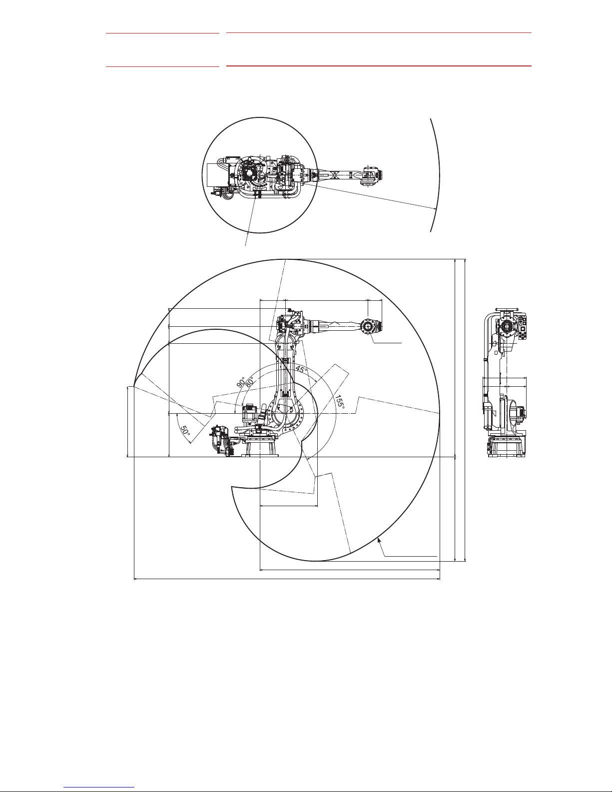
5.4 Dimensions and P-Point Maximum Envelope(5-3)
Fig. 5-3: Dimensions and P-Point Maximum Envelope
R2236
R718
320 1025 175
P-point
224
210
870
540
873
2236
3803
718
2456
3751
1295
543
301
242
P-point maximum
envelope
Page 4

7.1 Peripheral Equipment Mounts (7-1 page)
4
163548-1CD
HW1481428
7 System Application
7.1 Peripheral Equipment Mounts (7-1 page)
The peripheral equipment mounts are provided on the U-axis (upper arm)
as shown in fig. 7-1 “Installing Peripheral Equipment” for easier
installation of the users’s system applications. The following conditions
shall be observed to attach or install peripheral equipment.
Fig. 7-1: Installing Peripheral Equipment
513
100
100
50
57
200
150 90
5050
6060
100
98.5
(pitch:1.25) (4 holes)
Tapped hole M8(depth:16)
A
(pitch:1.25) (4 holes)
Tapped hole M8(depth:16)
B
Mount the peripheral equipment
within this range.
Table 7-1: Constraint for Attaching
Section Application Note
A Cable processing Up to 80 kg for attaching load
mass including wrist load.
B Cable processing
and valve, etc mounting
Up to 10 kg.
49
N•m (5 kgf•m) max. for
increased moment amount of
upper arm
Page 5

7.2 Internal User I/O Wiring Harness and Air Lines for User’s System
Applications (7-2 page)
5
163548-1CD
HW1481428
7.2 Internal User I/O Wiring Harness and Air Lines for User’s
System Applications (7-2 page)
Internal user I/O wiring harness, encoder or power cables for external
axis, cables for primary source for welding power, thermostat transformer
cables and hoses for air or cooling are incorporated in the manipulator for
the drive of peripheral devices mounted on the upper arm as shown in
fig. 7-2 “Connectors for Internal User I/O Wiring Harness and Air Lines for
User’s applications” and ffig. 7-2 “Connectors for Internal User I/O Wiring
Harness and Air Lines for User’s applications”
Table 7-2: Internal User I/O Wiring Harness and Air Lines for Use’s Applications
Item Specification Conditions
Internal user I/O wiring
harness
0.5 mm
2
× 23 wires For the pin allocation, refer to
.fig. 7-3 “Details of the
Connector Pin NUmbers” at
page 7-4
5.8 A or less per a wire.
The total current value must be
36 A or less.
Encoder cable for
external axis
0.2 mm
2
× 6 cables 3.9 A or less per a wire.
The total current value must be
12.8 A or less.
Power cable for
external axis
2 mm
2
× 4 cables
0.75 mm2 × 2 cables
2 mm2: 16.1 A or less per a wire
0.75 mm2: 9.0 A or less per a wire
The total current value must be
51.4 A or less.
Cable for primary
source for welding
21 mm
2
× 2 cables
10 mm
2
× 1 cable
1)
21 mm2: 150 A or less per a wire
The total current value must be
255 A or less.
Cable for thermostat
transformer
0.75 mm
2
× 3 cables 7.7 A or less per a wire
The total current value must be
29.2 A or less.
Air hose Inside dia. 8.0 mm × 1 hose 490 kPa (5 kgf/cm
2
) or less
Hose for cooling Inside dia. 6.5 mm × 6 hoses 300 kPa (5 kgf/cm
2
) or less
1 For ground wires
Page 6

7.2 Internal User I/O Wiring Harness and Air Lines for User’s System
Applications (7-2 page)
6
163548-1CD
HW1481428
Fig. 7-2: Connectors for Internal User I/O Wiring Harness and Air Lines for
User’s applications
A
B
View B
Dimensions vary depending on the external cable specifications.
Exhaust (air)
KQE12-03
Cooling water OUT3
KQE10-03
Cooling water OUT2
KQE10-03
Cooling water OUT1
KQE10-03
Cooling water IN3
KQE10-03
Cooling water IN1
KQE10-03
Cooling water IN2
KQE10-03
Air inlet
KQE12-03
Cooling water IN1
F10-03MS
Cooling water OUT1
F10-03MS
Cooling water IN2
F10-03MS
Cooling water OUT2
F10-03MS
Cooling water IN3
F10-03MS
Cooling water OUT3
F10-03MS
View A
For the folloing cables, terminal blocks are prepared in the box:
-Cables for the primary source for welding power
-Cables for the thermostat transformer
C2BG3236 (SANKEI)
Connector for the internal I/O wiring harness:
Prepare pin connector JL05-6A24-28S
JL05-2A24-28PC
(socket connector with a cap)
Connector for the primary source for welding
Prepare pin connector MS3106B36-3P
MS3100A36-3S (with a cap)
and for the cables of extenal damage detector
Connector for the internal I/O wiring harness:
Prepare pin connector JL05-6A24-28P
JL05-2A24-28SC
(socket connector with a cap)
Connector for the external axis power cable:
Prepare pin connector JL05-6A20-29P
JL05-2A20-29SC
(socket connector with a cap)
Connector for the external axis power cable:
Prepare pin connector JL05-6A18-1P
JL05-2A18-1SC-FO
(socket connector with a cap)
(socket connector with a cap)
Connector for the thermostat transformer:
Prepare pin connector MS3106B14S-1P
MS3100A14S-1S
Page 7

HW1481428
MANUAL NO.
Specifications are subject to change without notice
for ongoing product modifications and improvements.
MOTOMAN-MS80W
INSTRUCTIONS
SUPPLEMENTARY FOR TYPE: YR-MS0080W-A23
SUPPLEMENTARY FOR TYPE:
 Loading...