

Page 1

MOTOMAN-MPL300 II
1 of 100
INSTRUCTIONS
TYPE:
YR-MPL0300-J00 (DX200 STANDARD SPECIFICATION)
Upon receipt of the product and prior to initial operation, read these instructions thoroughly, and
retain for future reference.
MOTOMAN INSTRUCTIONS
MOTOMAN-MPL300 II INSTRUCTIONS
DX200 INSTRUCTIONS
DX200 OPERATOR’S MANUAL (for each purpose)
DX200 MAINTENANCE MANUAL
The DX200 operator’s manual above corresponds to specific usage. Be sure to use the appropriate manual.
Part Number: 173124-1CD
Revision: 2
MANUAL NO.
HW1482991
2
Page 2

MPL300 II
2 of 100
173124-1CD
Copyright © 2018, 2015, 2014 Yaskawa America, Inc.
Terms of Use and Copyright Notice
All rights reserved. This manual is freely available as a service to Yaskawa
customers to assist in the operation of Motoman robots, related equipment
and software This manual is copyrighted property of Yaskawa and may
not be sold or redistributed in any way. You are welcome to copy this
document to your computer or mobile device for easy access but you may
not copy the PDF files to another website, blog, cloud storage site or any
other means of storing or distributing online content.
Printed in the United States of America
First Printing, 2014
Yaskawa America, Inc.
Motoman Robotics Division
100 Automation Way
Miamisburg, OH 45342
Phone: 937-847-6200
www.motoman.com
ii
HW1482991
Page 3

173124-1CD
MANDATORY
CAUTION
3 of 100
MPL300 II
• This instruction manual is intended to explain mainly on the
mechanical part of the MOTOMAN-MPL300 II for the application to
the actual operation and for proper maintenance and inspection. It
describes on safety and handling, details on specifications,
necessary items on maintenance and inspection, to explain
operating instructions and maintenance procedures. Be sure to
read and understand this instruction manual thoroughly before
installing and operating the manipulator.
• General items related to safety are listed in Chapter 1: Safety of the
DX200 Instructions. To ensure correct and safe operation, carefully
read the DX200 Instructions before reading this manual.
• Some drawings in this manual are shown with the protective covers
or shields removed for clarity. Be sure all covers and shields are
replaced before operating this product.
• The drawings and photos in this manual are representative
examples and differences may exist between them and the
delivered product.
• YASKAWA may modify this model without notice when necessary
due to product improvements, modifications, or changes in
specifications.
If such modification is made, the manual number will also be
revised.
• If your copy of the manual is damaged or lost, contact a YASKAWA
representative to order a new copy. The representatives are listed
on the back cover. Be sure to tell the representative the manual
number listed on the front cover.
• YASKAWA is not responsible for incidents arising from unauthorized
modification of its products. Unauthorized modification voids your
product's warranty.
iii
HW1482991
Page 4

MPL300 II
DANGER
WARNING
CAUTION
MANDATORY
PROHIBITED
NOTE
4 of 100
Notes for Safe Operation
Notes for Safe Operation
Read this manual carefully before installation, operation, maintenance, or
inspection of the MOTOMAN-MPL300 II.
In this manual, the Notes for Safe Operation are classified as “DANGER”,
“WARNING”, “CAUTION”, “MANDATORY”, or “PROHIBITED”.
173124-1CD
Indicates an imminent hazardous
situation which, if not avoided, could
result in death or serious injury to
personnel.
Indicates a potentially hazardous
situation which, if not avoided, could
result in death or serious injury to
personnel.
Indicates a potentially hazardous
situation which, if not avoided, could
result in minor or moderate injury to
personnel and damage to
equipment. It may also be used to
alert against unsafe practices.
Always be sure to follow explicitly
the items listed under this heading.
Must never be performed.
Even items described as “CAUTION” may result in a serious accident in
some situations.
At any rate, be sure to follow these important items.
To ensure safe and efficient operation at all times, be sure
to follow all instructions, even if not designated as
“DANGER”, “WARNING” and “CAUTION” .
DANGER
• Maintenance and inspection must be performed by specified
personnel.
Failure to observe this caution may result in electric shock or injury.
• For disassembly or repair, contact your YASKAWA representative.
• Do not remove the motor, and do not release the brake.
Failure to observe these safety precautions may result in death or
serious injury from unexpected turning of the manipulator's arm.
iv
HW1482991
Page 5

173124-1CD
TURN
5 of 100
MPL300
II
Notes for Safe Operation
WARNING
• Before operating the manipulator, check that servo power is turned
OFF pressing the emergency stop buttons.
When the servo power is turned OFF, the SERVO ON LED on the
programming pendant is turned OFF.
Injury or damage to machinery may result if the emergency stop circuit
cannot stop the manipulator during an emergency. The manipulator
should not be used if the emergency stop buttons do not function.
Fig. : Emergency Stop Button
• Once the emergency stop button is released, clear the cell of all
items which could interfere with the operation of the manipulator.
Then turn the servo power ON.
Injury may result from unintentional or unexpected manipulator motion.
Fig. : Release of Emergency Stop
• Observe the following precautions when performing teaching
operations within the P-point maximum envelope of the
manipulator:
– Be sure to use a lockout device to the safeguarding when going
inside. Also, display the sign that the operation is being
performed inside the safeguarding and make sure no one closes
the safeguarding.
– View the manipulator from the front whenever possible.
– Always follow the predetermined operating procedure.
– Keep in mind the emergency response measures against the
manipulator’s unexpected motion toward you.
– Ensure that you have a safe place to retreat in case of
emergency.
Improper or unintended manipulator operation may result in injury.
• Confirm that no person is present in the P-point maximum envelope
of the manipulator and that you are in a safe location before:
– Turning ON the power for the DX200.
– Moving the manipulator with the programming pendant.
– Running the system in the check mode.
– Performing automatic operations.
Injury may result if anyone enters the P-point maximum envelope of the
manipulator during operation. Always press an emergency stop button
immediately if there is a problem.
v
HW1482991
Page 6

MPL300 II
CAUTION
6 of 100
173124-1CD
Definition of Terms Used Often in This Manual
• Perform the following inspection procedures prior to conducting
manipulator teaching. If problems are found, repair them
immediately, and be sure that all other necessary processing has
been performed.
– Check for problems in manipulator movement.
– Check for damage to insulation and sheathing of external wires.
• Always return the programming pendant to the hook on the cabinet
of the DX200 after use.
The programming pendant can be damaged if it is left in the
manipulator's work area, on the floor, or near fixtures.
• Read and understand the Explanation of Warning Labels in the
DX200 Instructions before operating the manipulator:
Definition of Terms Used Often in This Manual
The MOTOMAN is the YASKAWA industrial robot product.
The MOTOMAN usually consists of the manipulator, the controller, the
programming pendant, and supply cables.
In this manual, the equipment is designated as follows:
Equipment Manual Designation
DX200 controller DX200
DX200 programming pendant Programming pendant
Cable between the manipulator and the
controller
Manipulator cable
Registered Trademark
In this manual, names of companies, corporations, or products are
trademarks, registered trademarks, or bland names for each company or
corporation. The indications of (R) and
TM
are omitted.
vi
HW1482991
Page 7

173124-1CD
7 of 100
MPL300
II
Explanation of Warning Labels
Explanation of Warning Labels
The following warning labels are attached to the manipulator.
Always follow the warnings on the labels.
Also, an identification label with important information is placed on the
body of the manipulator. Prior to operating the manipulator, confirm the
contents.
Note: Taking the maintenance-relevant trainings offered by YASKAWA is
indispensable for replacing the L-axis of the balancer-equipped
manipulator.
Fig. : Warning Label Locations
Nameplate
Nameplate
MODEL
MOTOMANTYPE
PAYLOAD
ORDER NO.
SERIAL NO.
YASKAWA ELECTRIC CORPORATION
2-1 Kurosakishiroishi, Yahatanishi-ku,
Kitakyushu 806-0004 Japan
MADE IN JAPAN
MASS
kg
DATE
WARNING label A
WARNING Label A:
kg
WARNING Label B:
WARNING Label C
WARNING
Moving parts
may cause
injury
WARNING
Do not enter
robot
work area.
WARNING Label B
WARNING Label C:
DANGER
Do not remove the motor,and do not
release the brake. Failure to observe
this caution may result in injury from
unexpected turning of the manipulator arm.
Please contact your Yaskawa representive.
vii
HW1482991
Page 8

MPL300 II
8 of 100
Signal Output for Motor Protection
Signal Output for Motor Protection
A cooling fan is equipped in order to protect the motor of S-axis of the
manipulator from overheating. If the cooling fan is aut of ordet, warning
message [COOLING FAN2 ERROR] will appear on the programming
pendant.
If operation is continued while this warning message remains displayed,
the component parts of the DX200 and robot components are liable to
become damaged, leading to a major breakdown.
During high speed continuous operation, the temperature may rise
abruptly depending upon the ambient temperature and the operation
pattern, so it is necessary to promptly detect a warning.
A warning message is output as a dedicated output signal, so it is
recommended that you monitor it on the system side as a warning signal
for the sake of safety.
Refer to “DX200 Concurrent I/O” for details on the signal output.
173124-1CD
Safeguarding Tips
All operators, programmers, maintenance personnel, supervisors, and
anyone working near the system must become familiar with the operation
of this equipment. All personnel involved with the operation of the
equipment must understand potential dangers of operation. General
safeguarding tips are as follows:
Table: Dedicated output signal
80290
SOUT#0575
COOLING FAN2 ERROR
• Improper operation can result in personal injury and/or damage to
the equipment. Only trained personnel familiar with the operation of
this equipment, the operator's manuals, the system equipment, and
options and accessories should be permitted to operate this
equipment.
• Improper connections can damage the equipment. All connections
must be made within the standard voltage and current ratings of the
equipment.
• The system must be placed in Emergency Stop (E-Stop) mode
whenever it is not in use.
• In accordance with ANSI/RIA R15.06-2012, section 4.2.5, Sources of
Energy, use lockout/tagout procedures during equipment
maintenance. Refer also to Section 1910.147 (29CFR, Part 1910),
Occupational Safety and Health Standards for General Industry
(OSHA).
viii
HW1482991
Page 9

173124-1CD
9 of 100
MPL300
II
Mechanical Safety Devices
Mechanical Safety Devices
The safe operation of this equipment is ultimately the users responsibility.
The conditions under which the equipment will be operated safely should
be reviewed by the user. The user must be aware of the various national
codes, ANSI/RIA R15.06-2012 safety standards, and other local codes
that may pertain to the installation and use of this equipment.
Additional safety measures for personnel and equipment may be required
depending on system installation, operation, and/or location. The following
safety equipment is provided as standard:
• Safety barriers
• Door interlocks
• Emergency stop palm buttons located on operator station
Check all safety equipment frequently for proper operation. Repair or
replace any non-functioning safety equipment immediately.
ix
HW1482991
Page 10

MPL300 II
10 of 100
Programming, Operation, and Maintenance Safety
Programming, Operation, and Maintenance Safety
All operators, programmers, maintenance personnel, supervisors, and
anyone working near the system must become familiar with the operation
of this equipment. Improper operation can result in personal injury and/or
damage to the equipment. Only trained personnel familiar with the
operation, manuals, electrical design, and equipment interconnections of
this equipment should be permitted to program, or maintain the system.
All personnel involved with the operation of the equipment must
understand potential dangers of operation.
• Inspect the equipment to be sure no potentially hazardous conditions
exist. Be sure the area is clean and free of water, oil, debris, etc.
• Be sure that all safeguards are in place. Check all safety equipment
for proper operation. Repair or replace any non-functioning safety
equipment immediately.
• Check the E-Stop button on the operator station for proper operation
before programming. The equipment must be placed in Emergency
Stop (E-Stop) mode whenever it is not in use.
173124-1CD
• Back up all programs and jobs onto suitable media before program
changes are made. To avoid loss of information, programs, or jobs, a
backup must always be made before any service procedures are
done and before any changes are made to options, accessories, or
equipment.
• Any modifications to the controller unit can cause severe personal
injury or death, as well as damage to the robot! Do not make any
modifications to the controller unit. Making any changes without the
written permission from Yaskawa will void the warranty.
• Some operations require a standard passwords and some require
special passwords.
• The equipment allows modifications of the software for maximum
performance. Care must be taken when making these modifications.
All modifications made to the software will change the way the
equipment operates and can cause severe personal injury or death,
as well as damage parts of the system. Double check all
modifications under every mode of operation to ensure that the
changes have not created hazards or dangerous situations.
• This equipment has multiple sources of electrical supply. Electrical
interconnections are made between the controller and other
equipment. Disconnect and lockout/tagout all electrical circuits
before making any modifications or connections.
• Do not perform any maintenance procedures before reading and
understanding the proper procedures in the appropriate manual.
• Use proper replacement parts.
• Improper connections can damage the equipment. All connections
must be made within the standard voltage and current ratings of the
equipment.
x
HW1482991
Page 11

173124-1CD
11 of 100
MPL300
II
Maintenance Safety
Maintenance Safety
Turn the power OFF and disconnect and lockout/tagout all electrical
circuits before making any modifications or connections.
Perform only the maintenance described in this manual. Maintenance
other than specified in this manual should be performed only by Yaskawatrained, qualified personnel.
Summary of Warning Information
This manual is provided to help users establish safe conditions for
operating the equipment. Specific considerations and precautions are also
described in the manual, but appear in the form of Dangers, Warnings,
Cautions, and Notes.
It is important that users operate the equipment in accordance with this
instruction manual and any additional information which may be provided
by Yaskawa. Address any questions regarding the safe and proper
operation of the equipment to Yaskawa Customer Support.
xi
HW1482991
Page 12
MPL300 II
NOTE
(937) 847-3200
12 of 100
Customer Support Information
Customer Support Information
If you need assistance with any aspect of your MPL300 II system, please
contact Customer Support at the following 24-hour telephone number:
For routine technical inquiries, you can also contact Customer Support at
the following e-mail address:
When using e-mail to contact Customer Support, please provide a
detailed description of your issue, along with complete contact
information. Please allow approximately 24 to 36 hours for a response to
your inquiry.
173124-1CD
techsupport@motoman.com
Please use e-mail for routine inquiries only. If you have an
urgent or emergency need for service, replacement parts,
or information, you must contact Customer Support at the
telephone number shown above.
Please have the following information ready before you call Customer
Support:
• System MPL300
• Primary Application ___________________________
• Controller DX200
• Software Version Access this information on the
Programming Pendant’s LCD
display screen by selecting {MAIN
MENU} - {SYSTEM INFO} {VERSION}
• Robot Serial Number Located on the robot data plate
• Robot Sales Order Number Located on the DX200 controller
data plate
II
xii
HW1482991
Page 13

173124-1CD
13 of 100
MPL300
II
Table of Contents
Table of Contents
1 Product Confirmation ...................................................................................................................... 1-1
1.1 Contents Confirmation ....................................................................................................... 1-1
1.2 Order Number Confirmation .............................................................................................. 1-2
2 Transport......................................................................................................................................... 2-1
2.1 Transport Method .............................................................................................................. 2-1
2.1.1 Using a Crane ...................................................................................................... 2-2
2.2 Shipping Bolts and Brackets.............................................................................................. 2-3
3 Installation....................................................................................................................................... 3-1
3.1 Installation of Safeguarding ............................................................................................... 3-1
3.2 Mounting Procedures for Manipulator Base ...................................................................... 3-2
3.2.1 Mounting the Manipulator and Fixture on the Baseplate ...................................... 3-3
3.3 Protection Class................................................................................................................. 3-4
3.4 Location ............................................................................................................................. 3-4
4 Wiring.............................................................................................................................................. 4-1
4.1 Grounding .......................................................................................................................... 4-1
4.2 Cable Connection .............................................................................................................. 4-2
4.2.1 Connection to the Manipulator.............................................................................. 4-2
4.2.2 Connection to the DX200 ..................................................................................... 4-2
5 Basic Specifications ........................................................................................................................ 5-1
5.1 Basic Specifications........................................................................................................... 5-1
5.2 Part Names and Working Axes.......................................................................................... 5-2
5.3 Manipulator Base Dimensions ........................................................................................... 5-2
5.4 Dimensions and T-Point Maximum Envelope.................................................................... 5-3
5.5 Stopping Angle and Time at the Emergency Stop............................................................. 5-4
5.5.1 Stop Categiry 0: Emergency Stop ........................................................................ 5-4
5.5.1.1 Position 100% ......................................................................................... 5-4
5.5.1.2 Position 66% ........................................................................................... 5-5
5.5.1.3 Position 33% ........................................................................................... 5-5
5.5.2 Stop Category 1: Emergency Stop....................................................................... 5-6
xiii
HW1482991
Page 14

173124-1CD
14 of 100
MPL300 II
5.6 Alterable Operating Range ................................................................................................ 5-7
5.6.1 Components for Altering Operating Range........................................................... 5-8
5.6.2 Notes on the Mechanical Stopper Installation ...................................................... 5-9
5.6.3 Adjustment of the Soft Limit of the S-Axis Pulse ................................................ 5-10
6 Allowable Load for Wrist Axis and Wrist Flange ............................................................................. 6-1
6.1 Allowable Wrist Load ......................................................................................................... 6-1
6.2 Wrist Flange....................................................................................................................... 6-2
6.3 Levelness of the Wrist Flange............................................................................................ 6-3
7 System Application.......................................................................................................................... 7-1
7.1 Peripheral Equipment Mounts............................................................................................ 7-1
7.2 Internal User I/O Wiring Harness and Air Line................................................................... 7-2
Table of Contents
8 Electrical Equipment Specification.................................................................................................. 8-1
8.1 Position of Limit Switch ...................................................................................................... 8-1
8.2 Internal Connections .......................................................................................................... 8-2
9 Maintenance and Inspection ........................................................................................................... 9-1
9.1 Inspection Schedule........................................................................................................... 9-1
9.2 Notes on Maintenance Procedures.................................................................................... 9-5
9.2.1 Battery Pack Replacement ................................................................................... 9-5
9.3 Grease Replenishment/Exchange ..................................................................................... 9-7
9.3.1 Notes on Grease Replenishment/Exchange Procedures .....................................9-7
9.3.2 Grease Replenishment/Exchange for S-Axis Speed Reducer and Gear ............. 9-8
9.3.2.1 Grease Replenishment............................................................................ 9-8
9.3.2.2 Grease Exchange.................................................................................... 9-9
9.3.3 Grease Replenishment/Exchange for L-Axis Speed Reducer............................ 9-10
9.3.3.1 Grease Replenishment.......................................................................... 9-11
9.3.3.2 Grease Exchange.................................................................................. 9-12
9.3.4 Grease Replenishment/Exchange for U-Axis Speed Reducer ........................... 9-13
9.3.4.1 Grease Replenishment.......................................................................... 9-13
9.3.4.2 Grease Exchange.................................................................................. 9-14
9.3.5 Grease Replenishment/Exchange for T-Axis Speed Reducer............................ 9-15
9.3.5.1 Grease Replenishment.......................................................................... 9-15
9.3.5.2 Grease Exchange.................................................................................. 9-16
9.3.6 Grease Replenishment for U-axis Cross Roller Bearing .................................... 9-17
9.3.7 Grease Replenishment for Links ........................................................................ 9-18
xiv
HW1482991
Page 15

173124-1CD
15 of 100
MPL300
10 Recommended Spare Parts........................................................................................................ 10-1
11 Parts List ..................................................................................................................................... 11-1
II
9.3.8 Notes for Maintenance ....................................................................................... 9-20
9.3.8.1 Battery Pack Connection....................................................................... 9-20
11.1 S-Axis Unit ..................................................................................................................... 11-1
11.2 L-Axis Unit ..................................................................................................................... 11-4
11.3 U-Axis Unit..................................................................................................................... 11-8
11.4 Wrist Unit ..................................................................................................................... 11-10
11.5 Balancer Unit ............................................................................................................... 11-13
Table of Contents
xv
HW1482991
Page 16

MPL300 II
CAUTION
16 of 100
1 Product Confirmation
1.1 Contents Confirmation
1 Product Confirmation
• Confirm that the manipulator and the DX200 have the same order
number. Special care must be taken when more than one
manipulator is to be installed.
If the numbers do not match, manipulators may not perform as
expected and cause injury or damage.
1.1 Contents Confirmation
Confirm the contents of the delivery when the product arrives.
Standard delivery includes the following four items (information for the
content of optional goods are given separately):
173124-1CD
• Manipulator
• DX200
• Programming pendant
• Manipulator cables
1-1
HW1482991
Page 17

173124-1CD
17 of 100
MPL300
II
1 Product Confirmation
1.2 Order Number Confirmation
1.2 Order Number Confirmation
Check that the order number of the manipulator corresponds to the
DX200. The order number is located on a label as shown below.
Fig. 1-1: Location of Order Number Labels
Label (Enlarged View)
THE MANIPULATOR AND THE CONTROLLER
SHOULD HAVE SAME ORDER NUMBER.
ORDER NO.
Check that the manipulator
and the DX200 have the
same order number.
(a) DX200 (Front View)
(b) Manipulator (Side View)
1-2
HW1482991
Page 18

MPL300 II
CAUTION
NOTE
18 of 100
2 Transport
173124-1CD
2 Transport
2.1 Transport Method
• Sling applications and crane or forklift operations must be
performed by authorized personnel only.
Failure to observe this caution may result in injury or damage.
• Avoid excessive vibration or shock during transport.
The system consists of precision components. Failure to observe this
caution may adversely affect performance.
2.1 Transport Method
• The weight of the manipulator is approximately 1865kg
including the shipping bolts and brackets. Use a wire rope
strong enough to withstand the weight.
• Shipping bolts and brackets are designed to support the
manipulator weight. Do not use them for anything other
than transporting the manipulator.
• Mount the shipping bolts and brackets for transporting the
manipulator.
• Avoid putting external force on the arm or motor unit when
transporting by a crane or other equipment. Failure to
observe this instruction may result in injury.
2-1
HW1482991
Page 19

173124-1CD
Axis
Angle
Pulse
Factory setting for angle and pulse of each axis
SLUT
00
-94720 -52622
25
45
19 of 100
MPL300
II
2 Transport
2.1 Transport Method
2.1.1 Using a Crane
As a rule, the manipulator should be lifted by a crane with four wire ropes
when removing it from the package and moving it. Be sure that the
manipulator is fixed with the shipping bolts and brackets before transport,
and lift it in the posture as shown in Fig. 2-1 “Transporting Position”.
Fig. 2-1: Transporting Position
2-2
HW1482991
Page 20

MPL300 II
NOTE
20 of 100
173124-1CD
2 Transport
2.2 Shipping Bolts and Brackets
2.2 Shipping Bolts and Brackets
The manipulator is provided with shipping bolts and brackets at positions
A, B, and C. (See Fig. 2-1 “Transporting Position”.)
• The shipping bolts and brackets are painted yellow.
Position Screw Type Pcs
A Hexagon socket head cap screw M20 4
B and C Hexagon socket head cap screw M10 4
Before turning ON the power, check to be sure that the
shipping bolts and brackets are removed. The shipping
bolts and brackets then must be stored for future use, in the
event that the manipulator must be moved again.
Fig. 2-2: Shipping Bolts and Brackets
C
B
A
2-3
HW1482991
Page 21

173124-1CD
CAUTION
21 of 100
MPL300
II
3 Installation
3 Installation
3.1 Installation of Safeguarding
WARNING
• Install the safeguarding.
Failure to observe this warning may result in injury or damage.
• Install the manipulator in a location where the tool or the workpiece
held by its fully extended arm will not reach the wall, safeguarding,
or controller.
Failure to observe this warning may result in injury or damage.
• Do not start the manipulator or even turn ON the power before it is
firmly anchored.
The manipulator may overturn and cause injury or damage.
• Do not install or operate the manipulator that is damaged or lacks
parts.
Failure to observe this caution may cause injury or damage.
• Before turning ON the power, check to be sure that the shipping
bolts and brackets explained in Fig. 2-2 “Shipping Bolts and
Brackets” are removed.
Failure to observe this caution may result in damage to the driving
parts.
3.1 Installation of Safeguarding
To insure safety, be sure to install the safeguarding. They prevent
unforeseen accidents with personnel and damage to equipment. The
following is quoted for the information and guidance.
Responsibility for Safeguarding (ISO 10218)
Responsibility for Safeguarding (ISO 10218)
The user of a manipulator or robot system shall ensure that the
safeguarding is provided and used in accordance with Chapter 6, 7, and 8
of this standard. The means and degree of safeguarding, including any
redundancies, shall correspond directly to the type and level of hazard
presented by the robot system consistent with the robot application.
Safeguarding may include but not be limited to safeguarding devices,
barriers, interlock barriers, perimeter guarding, awareness barriers, and
awareness signals.
3-1
HW1482991
Page 22

MPL300 II
22 of 100
3 Installation
3.2 Mounting Procedures for Manipulator Base
3.2 Mounting Procedures for Manipulator Base
The manipulator should be firmly mounted on a baseplate or foundation
strong enough to support the manipulator and withstand repulsion forces
during acceleration and deceleration.
Construct a solid foundation with the appropriate thickness to withstand
maximum repulsion forces of the manipulator as shown in Table 3-1
“Manipulator Repulsion Force and Torque”.
During installation, if the flatness is not right, the manipulator shape may
be deformed and its functional ability may be compromised. The flatness
for baseplate must be kept at 0.5 mm or less. Fix the manipulator base as
described in section 3.2.1 “Mounting the Manipulator and Fixture on the
Baseplate”.
Table 3-1: Manipulator Repulsion Force and Torque
Horizontal rotation Vertical rotation
Repulsion force F
Emergency stop 20580 N
(2100 kgf)
Acceleration/deceleration 6370 N
(650 kgf)
Torque M
H
39200 N•m
(4000 kgf•m)
11760 N•m
(1200 kgf•m)
173124-1CD
H
Repulsion force FVTorque M
49980 N
(5100 kgf)
21560 N
(2200 kgf)
62720 N•m
(6400 kgf•m)
15680 N•m
(1600 kgf•m)
V
Fig. 3-1: Manipulator Repulsion Force and Torque
M
V
FV
M
H
F
H
3-2
HW1482991
Page 23

173124-1CD
Hexagon socket head cap screw M20 (8 screws)
Spring washer
Manipulator base
Baseplate
Washer
50 mm
or more
200 mm or more
Flatness: 0.5 mm or less
Manipulator base
Baseplate
28 dia. (12 holes)
Baseplate (reference)
Units: mm
Anchor bolt (M24 or larger)
180
540
1000
180
180
540
180
1000
23 of 100
MPL300
II
3 Installation
3.2 Mounting Procedures for Manipulator Base
3.2.1 Mounting the Manipulator and Fixture on the Baseplate
For the first process, anchor the baseplate firmly on the floor. The
baseplate should have enough rigidity, which is 50 mm or more in
thickness. The size of the anchor bolt recommended for the baseplate
fixation is M24 or more.
Next, fix the manipulator base to the baseplate. There are eight mounting
holes on the manipulator base: securely fix the manipulator to the
baseplate using eight hexagon head screws M20 (Tensile strength:
1200 N/mm
2
or more) (80 mm long is recommended). Tighten the bolts
with a tightening torque of 402 N•m (41 kgf•m). Tighten the hexagon head
screws and anchor bolts firmly so that they will not be loosened during the
operation.
Fig. 3-2: Mounting the Manipulator on Baseplate
3-3
HW1482991
Page 24

MPL300 II
24 of 100
173124-1CD
3 Installation
3.3 Protection Class
3.3 Protection Class
For the standard type, environmental resistance for main part of the
manipulator conforms to IP54; the wrist part conforms to IP67.
3.4 Location
When installing a manipulator, it is necessary to satisfy the following
environmental conditions:
• Ambient temperature: 0° to + 45°C
• Humidity: 20 to 80 %RH (non-condensing)
• Free from dust, soot, or water
• Free from corrosive gas or liquid, or explosive gas or liquid
• Free from excessive vibration
(Vibration acceleration: 4.9 m/s
• Free from large electrical noise (plasma)
• Flatness for installation: 0.5 mm or less
2
[0.5 G] or less)
3-4
HW1482991
Page 25

173124-1CD
CAUTION
NOTE
A
Bolt M8 (for grounding)
Delivered with the manipulator
5.5 mm2 or more
Enlarged View A
25 of 100
MPL300
II
4Wiring
4 Wiring
4.1 Grounding
WARNING
• Ground resistance must be 100 Ω or less.
Failure to observe this warning may result in fire or electric shock.
• Before wiring, make sure to turn the primary power supply off, and
put up a warning sign. (ex. DO NOT TURN THE POWER ON.)
Failure to observe this warning may result in fire or electric shock.
• Wiring must be performed by authorized or certified personnel.
Failure to observe this caution may result in fire or electric shock.
• DO NOT cover the cable with heat insulating material, and avoid
multiple cabling when laying manipulator cables from the
manipulator to the DX200.
Failure to observe this caution may result in burn caused by cable heat
emission failure.
4.1 Grounding
Follow electrical installation standards and wiring regulations for
grounding. A ground wire of 5.5 mm
Refer to Fig. 4-1 “Grounding Method” to connect the ground line directly to
the manipulator.
Fig. 4-1: Grounding Method
2
or more is recommended.
• Never use this wire sharing with other ground lines or
grounding electrodes for other electric power, motor
power, welding devices, etc.
• Where metal ducts, metallic conduits, or distributing racks
are used for cable laying, ground in accordance with
electrical installation standards.
4-1
HW1482991
Page 26
MPL300 II
NOTE
Power Cable
DX200 side
Encoder Cable
Manipulator side
DX200 side Manipulator side
1BC
2BC
;
%&
;
%&
2BC
X21
+:
%&
;
26 of 100
173124-1CD
4 Wiring
4.2 Cable Connection
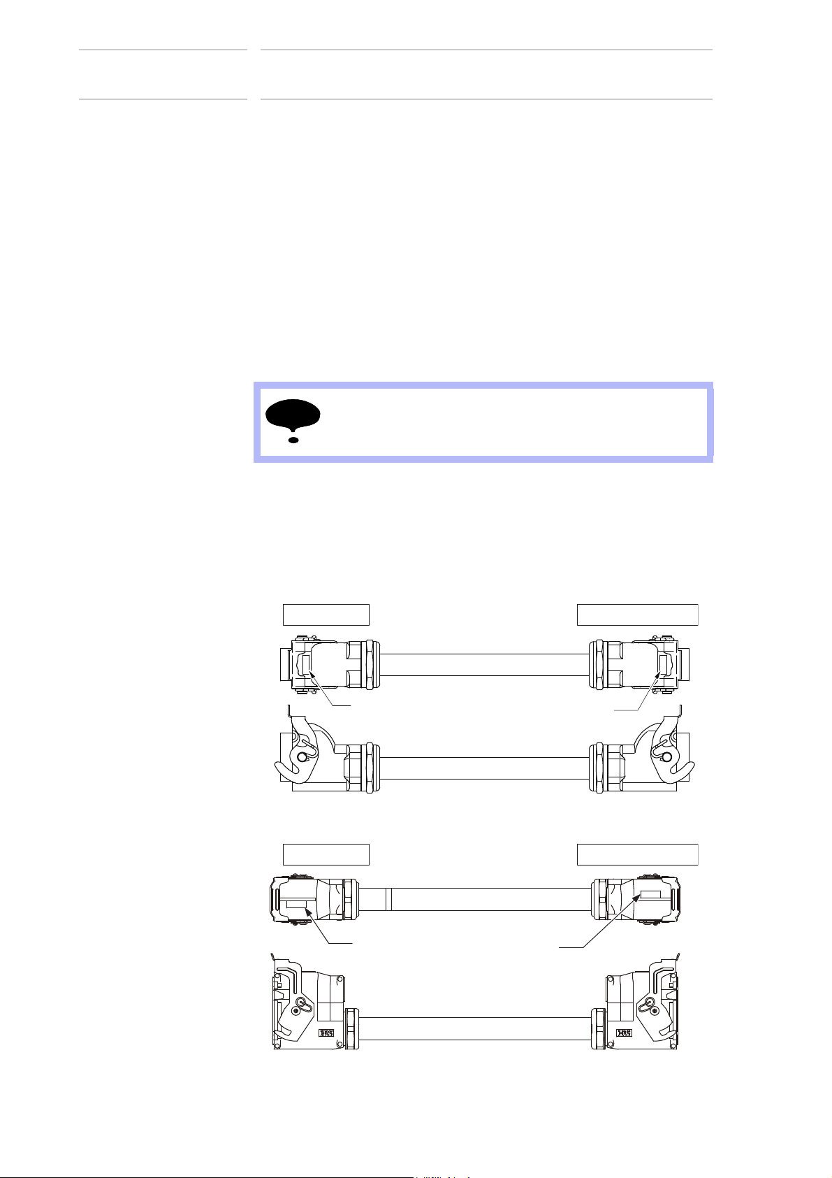
4.2 Cable Connection
Three manipulator cables are delivered with the manipulator: an encoder
cable (1BC) and an power cable (2BC).
(Refer to Fig. 4-2 “Manipulator Cables”.)
Connect these cables to the manipulator base connectors and to the
DX200. Refer to Fig. 4-3(a) “Manipulator Cable Connectors (Manipulator
Side)” .
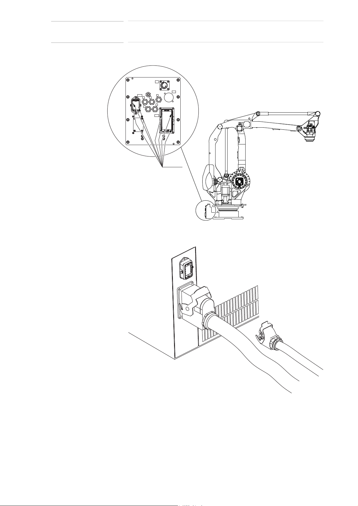
4.2.1 Connection to the Manipulator
Before connecting two cables to the manipulator, verify the numbers on
both manipulator cables and the connectors on the connector base of the
manipulator. When connecting, adjust the cable connector positions to
the main key positions of the manipulator, and insert cables in the order of
2BC then 1BC. After inserting the cables, depress the lever until it clicks.
DO NOT cover the cable with heat insulating material, and
avoid multiple cabling.
4.2.2 Connection to the DX200
Before connecting cables to the DX200, verify the numbers on both
manipulator cables and the connectors on the DX200. When connecting,
insert the cables in the order of X21 then X11, and depress each lever
until it clicks.
Fig. 4-2: Manipulator Cables
4-2
HW1482991
Page 27
173124-1CD
Key
positions
S1
2BC
1BC
FB
C
D
E
AB
X21
X11
27 of 100
MPL300
II
4 Wiring
4.2 Cable Connection
Fig. 4-3(a): Manipulator Cable Connectors (Manipulator Side)
Fig. 4-3(b): Manipulator Cable Connection (DX200 Side)
4-3
HW1482991
Page 28

MPL300 II
28 of 100
5 Basic Specifications
5.1 Basic Specifications
5 Basic Specifications
5.1 Basic Specifications
173124-1CD
Table 5-1: Basic Specifications
Item Type MOTOMAN-MPL300II
Structure Vertically Articulated
Degree of Freedom 4
Payload 300 kg
Repeatability
Range of Motion S-Axis (turning) -180° − +180°
Maximum Speed S-Axis 1.57 rad/s, 90° /s
T-Axis Allowable Inertia (GD
Approx. Mass 1820 kg
Protective Structure Main part of the manipulator: IP54 or equivalent
Ambient Conditions Temperature 0 to 45°C
Power Requirements 8.0 kVA
Noise
1 SI units are used in this table. However, gravitational unit is used in ( ).
2 Conformed to ISO9283
3 Refer to section 6.1 “Allowable Wrist Load” for details on the permissible moment of inertia.
4 Conformed to ISO6926
1, Measurement is carried out when the maximum load is mounted to the manipulator and operated
2, Measurement is carried out:
- between 1.2m and 1.5m above the ground.
- 400mm away from the P-point maximum envelope.
2)
4)
in the maximum speed.
1)
YR-MPL0300-J00
±0.5 mm
L-Axis (lower arm) -45° − +90°
U-Axis (upper arm) -120° − +15.5°
T-Axis (wrist twist) -360° − +360°
L-Axis 1.75 rad/s, 100° /s
U-Axis 1.92 rad/s, 110° /s
T-Axis 3.40 rad/s, 195° /s
2
3)
/4)
Humidity 20 to 80% RH (non-condensing)
Vibration 4.9 m/s
Others Free from corrosive gas or liquid, or explosive gas or
140 kg•m
Wrist axis only: IP67 or equivalent
liquid
Free from exposure to dust, soot, or oil
Free from excessive electrical noise (plasma)
70dB
2
2
(0.5G) or less
5-1
HW1482991
Page 29
173124-1CD
S+
S-
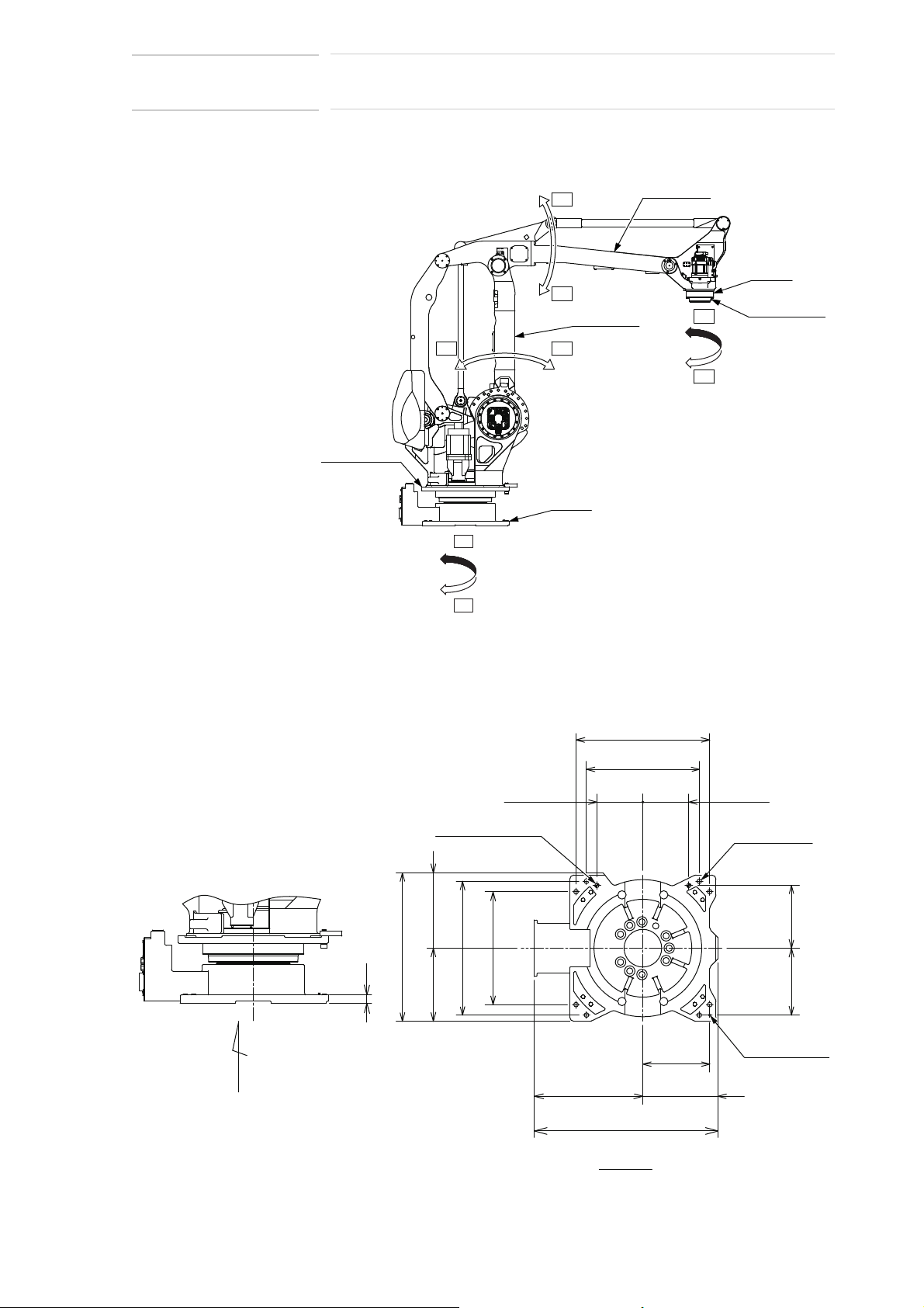
Lower arm
(L-arm)
Base
Upper arm
(U-arm)
Wrist
Wrist flange
Rotary head
(S-head)
T-
T+
U-
U+
L- L+
40
540
540
A
710
350
879
519
640
640
Units: mm
View A
360±0.1
320±0.1
360±0.1
+0.021
0
20 dia. hole
(2 places)
12 dia. hole
+0.018
0
22 dia. hole
(8 places)
220±0.1
220±0.1
300±0.1320±0.1
29 of 100
MPL300
II
5 Basic Specifications
5.2 Part Names and Working Axes
5.2 Part Names and Working Axes
Fig. 5-1: Part Names and Working Axes
Fig. 5-2: Manipulator Base Dimensions
5.3 Manipulator Base Dimensions
5-2
HW1482991
Page 30

MPL300 II
-point maximum envelope
T
Units: mm
T
-Point
P-point
625
616
16
2529
R1124
2776
614 2162
1300
1300
1600
1600
2363
2624
1241
45
90
F
R1037
R3159
2204
300
250
1400
0
820
31591037
R697
880 1250
270
0
120
30 of 100
173124-1CD
5 Basic Specifications
5.4 Dimensions and T-Point Maximum Envelope
5.4 Dimensions and T-Point Maximum Envelope
Fig. 5-3:
Dimensions and T-Point Maximum Envelope
5-3
HW1482991
Page 31

173124-1CD
㻜㻚㻞
㻜㻚㻠
㻜㻚㻢
㻜㻚㻤
㻝㻚㻜
㻜㻟㻜㻢㻜㻥㻜㻝㻞㻜
㻿㼠㼛㼜㼜㼕㼚㼓㻌㼠㼕㼙㼑㼇㼟㼑㼏㼉
㻿㼜㼑㼑㼐㼇㼐㼑㼓㻛㼟㼉
㻿㼠㼛㼜㻌㼜㼛㼟㼕㼠㼕㼛㼚㻌㼛㼒㻌㻿㻙㼍㼤㼕㼟㻌㼏㼍㼠㼑㼓㼛㼞㼥㻜㻌㻝㻜㻜㻑
㻸㼛㼍㼐㻝㻜㻜㻑 㻸㼛㼍㼐㻢㻢㻑 㻸㼛㼍㼐㻟㻟㻑
㻜
㻡
㻝㻜
㻝㻡
㻞㻜
㻞㻡
㻟㻜
㻟㻡
㻜㻟㻜㻢㻜㻥㻜㻝㻞㻜
㻿㼠㼛㼜㼜㼕㼚㼓㻌㼍㼚㼓㼘㼑㼇㼐㼑㼓㼉
㻿㼜㼑㼑㼐㼇㼐㼑㼓㻛㼟㼉
㻿㼠㼛㼜㻌㼜㼛㼟㼕㼠㼕㼛㼚㻌㼛㼒㻌㻿㻙㼍㼤㼕㼟㻌㼏㼍㼠㼑㼓㼛㼞㼥㻜㻌㻝㻜㻜㻑㻌
㻸㼛㼍㼐㻝㻜㻜㻑 㻸㼛㼍㼐㻢㻢㻑 㻸㼛㼍㼐㻟㻟㻑
㻜
㻡
㻝㻜
㻝㻡
㻞㻜
㻞㻡
㻟㻜
㻟㻡
㻜㻟㻜㻢㻜㻥㻜㻝㻞㻜
㻿㼠㼛㼜㼜㼕㼚㼓㻌㼍㼚㼓㼘㼑㼇㼐㼑㼓㼉
㻿㼜㼑㼑㼐㼇㼐㼑㼓㻛㼟㼉
㻿㼠㼛㼜㻌㼜㼛㼟㼕㼠㼕㼛㼚㻌㼛㼒㻌㻸㻙㼍㼤㼕㼟㻌㼏㼍㼠㼑㼓㼛㼞㼥㻜㻌㻝㻜㻜㻑
㻸㼛㼍㼐㻝㻜㻜㻑 㻸㼛㼍㼐㻢㻢㻑 㻸㼛㼍㼐㻟㻟㻑
㻜㻚㻜
㻜㻚㻝
㻜㻚㻞
㻜㻚㻟
㻜㻚㻠
㻜㻚㻡
㻜㻟㻜㻢㻜㻥㻜㻝㻞㻜
㻿㼠㼛㼜㼜㼕㼚㼓㻌㼠㼕㼙㼑㼇㼟㼑㼏㼉
㻿㼜㼑㼑㼐㼇㼐㼑㼓㻛㼟㼉
㻿㼠㼛㼜㻌㼜㼛㼟㼕㼠㼕㼛㼚㻌㼛㼒㻌㻸㻙㼍㼤㼕㼟㻌㼏㼍㼠㼑㼓㼛㼞㼥㻜㻌㻝㻜㻜㻑
㻸㼛㼍㼐㻝㻜㻜㻑 㻸㼛㼍㼐㻢㻢㻑 㻸㼛㼍㼐㻟㻟㻑
㻜
㻡
㻝㻜
㻝㻡
㻞㻜
㻞㻡
㻟㻜
㻟㻡
㻜㻟㻜㻢㻜㻥㻜㻝㻞㻜
㻿㼠㼛㼜㼜㼕㼚㼓㻌㼍㼚㼓㼘㼑㼇㼐㼑㼓㼉
㻿㼜㼑㼑㼐㼇㼐㼑㼓㻛㼟㼉
㻿㼠㼛㼜㻌㼜㼛㼟㼕㼠㼕㼛㼚㻌㼛㼒㻌㼁㻙㼍㼤㼕㼟㻌㼏㼍㼠㼑㼓㼛㼞㼥㻜㻌㻝㻜㻜㻑
㻸㼛㼍㼐㻝㻜㻜㻑 㻸㼛㼍㼐㻢㻢㻑 㻸㼛㼍㼐㻟㻟㻑
㻜㻚㻜
㻜㻚㻝
㻜㻚㻞
㻜㻚㻟
㻜㻚㻠
㻜㻚㻡
㻜㻟㻜㻢㻜㻥㻜㻝㻞㻜
㻿㼠㼛㼜㼜㼕㼚㼓㻌㼠㼕㼙㼑㼇㼟㼑㼏㼉
㻿㼜㼑㼑㼐㼇㼐㼑㼓㻛㼟㼉
㻿㼠㼛㼜㻌㼜㼛㼟㼕㼠㼕㼛㼚㻌㼛㼒㻌㼁㻙㼍㼤㼕㼟㻌㼏㼍㼠㼑㼓㼛㼞㼥㻜㻌㻝㻜㻜㻑
㻸㼛㼍㼐㻝㻜㻜㻑 㻸㼛㼍㼐㻢㻢㻑 㻸㼛㼍㼐㻟㻟㻑
31 of 100
MPL300
II
5 Basic Specifications
5.5 Stopping Angle and Time at the Emergency Stop
5.5 Stopping Angle and Time at the Emergency Stop
Following data on stopping angle and time at the emergency stop are
measured under the standard of ISO10218.
5.5.1 Stop Categiry 0: Emergency Stop
5.5.1.1 Position 100%
Fig. 5-4: Category 0, Position 100% : Stopping Angle and Time for each Axis at the Emergency Stop
(a)S-Axis
(b)L-Axis
(c)U-Axis
5-4
HW1482991
Page 32

173124-1CD
㻜㻚㻜
㻜㻚㻝
㻜㻚㻞
㻜㻚㻟
㻜㻚㻠
㻜㻚㻡
㻜㻟㻜㻢㻜㻥㻜㻝㻞㻜
㻿㼠㼛㼜㼜㼕㼚㼓㻌㼠㼕㼙㼑㼇㼟㼑㼏㼉
㻿㼜㼑㼑㼐㼇㼐㼑㼓㻛㼟㼉
㻿㼠㼛㼜㻌㼜㼛㼟㼕㼠㼕㼛㼚㻌㼛㼒㻌㻿㻙㼍㼤㼕㼟㻌㼏㼍㼠㼑㼓㼛㼞㼥㻜㻌㻢㻢㻑
㻸㼛㼍㼐㻝㻜㻜㻑 㻸㼛㼍㼐㻢㻢㻑 㻸㼛㼍㼐㻟㻟㻑
㻜
㻡
㻝㻜
㻝㻡
㻞㻜
㻞㻡
㻟㻜
㻟㻡
㻜㻟㻜㻢㻜㻥㻜㻝㻞㻜
㻿㼠㼛㼜㼜㼕㼚㼓㻌㼍㼚㼓㼘㼑㼇㼐㼑㼓㼉
㻿㼜㼑㼑㼐㼇㼐㼑㼓㻛㼟㼉
㻿㼠㼛㼜㻌㼜㼛㼟㼕㼠㼕㼛㼚㻌㼛㼒㻌㻿㻙㼍㼤㼕㼟㻌㼏㼍㼠㼑㼓㼛㼞㼥㻜㻌㻢㻢㻑
㻸㼛㼍㼐㻝㻜㻜㻑 㻸㼛㼍㼐㻢㻢㻑 㻸㼛㼍㼐㻟㻟㻑
㻜㻚㻜
㻜㻚㻝
㻜㻚㻞
㻜㻚㻟
㻜㻚㻠
㻜㻚㻡
㻜㻟㻜㻢㻜㻥㻜㻝㻞㻜
㻿㼠㼛㼜㼜㼕㼚㼓㻌㼠㼕㼙㼑㼇㼟㼑㼏㼉
㻿㼜㼑㼑㼐㼇㼐㼑㼓㻛㼟㼉
㻿㼠㼛㼜㻌㼜㼛㼟㼕㼠㼕㼛㼚㻌㼛㼒㻌㻿㻙㼍㼤㼕㼟㻌㼏㼍㼠㼑㼓㼛㼞㼥㻜㻌㻟㻟㻑
㻸㼛㼍㼐㻝㻜㻜㻑 㻸㼛㼍㼐㻢㻢㻑 㻸㼛㼍㼐㻟㻟㻑
㻜
㻡
㻝㻜
㻝㻡
㻞㻜
㻞㻡
㻟㻜
㻟㻡
㻜㻟㻜㻢㻜㻥㻜㻝㻞㻜
㻿㼠㼛㼜㼜㼕㼚㼓㻌㼍㼚㼓㼘㼑㼇㼐㼑㼓㼉
㻿㼜㼑㼑㼐㼇㼐㼑㼓㻛㼟㼉
㻿㼠㼛㼜㻌㼜㼛㼟㼕㼠㼕㼛㼚㻌㼛㼒㻌㻿㻙㼍㼤㼕㼟㻌㼏㼍㼠㼑㼓㼛㼞㼥㻜㻌㻟㻟㻑
㻸㼛㼍㼐㻝㻜㻜㻑 㻸㼛㼍㼐㻢㻢㻑 㻸㼛㼍㼐㻟㻟㻑
32 of 100
MPL300 II
5 Basic Specifications
5.5 Stopping Angle and Time at the Emergency Stop
5.5.1.2 Position 66%
Fig. 5-5: Category 0, Position 66% : Stopping Angle and Time for each Axis at the Emergency Stop
(a)S-Axis
Note: L- and U-axis takes one pose only for this structure.
5.5.1.3 Position 33%
Fig. 5-6: Category 0, Position 33% : Stopping Angle and Time for each Axis at the Emergency Stop
(a)S-Axis
Note: L-, U- axis takes one pose only for this structure.
5-5
HW1482991
Page 33

173124-1CD
㻜㻚㻜
㻜㻚㻞
㻜㻚㻠
㻜㻚㻢
㻜㻚㻤
㻝㻚㻜
㻜㻟㻜㻢㻜㻥㻜㻝㻞㻜
㻿㼠㼛㼜㼜㼕㼚㼓㻌㼠㼕㼙㼑㼇㼟㼑㼏㼉
㻿㼜㼑㼑㼐㼇㼐㼑㼓㻛㼟㼉
㻿㼠㼛㼜㻌㼜㼛㼟㼕㼠㼕㼛㼚㻌㼛㼒㻌㻿㻙㼍㼤㼕㼟㻌㼏㼍㼠㼑㼓㼛㼞㼥㻝
㻜
㻝㻜
㻞㻜
㻟㻜
㻠㻜
㻡㻜
㻜㻟㻜㻢㻜㻥㻜㻝㻞㻜
㻿㼠㼛㼜㼜㼕㼚㼓㻌㼍㼚㼓㼘㼑㼇㼐㼑㼓㼉
㻿㼜㼑㼑㼐㼇㼐㼑㼓㻛㼟㼉
㻿㼠㼛㼜㻌㼜㼛㼟㼕㼠㼕㼛㼚㻌㼛㼒㻌㻿㻙㼍㼤㼕㼟㻌㼏㼍㼠㼑㼓㼛㼞㼥㻝㻌
㻜㻚㻜
㻜㻚㻝
㻜㻚㻞
㻜㻚㻟
㻜㻚㻠
㻜㻚㻡
㻜㻚㻢
㻜㻟㻜㻢㻜㻥㻜㻝㻞㻜
㻿㼠㼛㼜㼜㼕㼚㼓㻌㼠㼕㼙㼑㼇㼟㼑㼏㼉
㻿㼜㼑㼑㼐㼇㼐㼑㼓㻛㼟㼉
㻿㼠㼛㼜㻌㼜㼛㼟㼕㼠㼕㼛㼚㻌㼛㼒㻌㻸㻙㼍㼤㼕㼟㻌㼏㼍㼠㼑㼓㼛㼞㼥㻝
㻜
㻝㻜
㻞㻜
㻟㻜
㻠㻜
㻡㻜
㻜㻟㻜㻢㻜㻥㻜㻝㻞㻜
㻿㼠㼛㼜㼜㼕㼚㼓㻌㼍㼚㼓㼘㼑㼇㼐㼑㼓㼉
㻿㼜㼑㼑㼐㼇㼐㼑㼓㻛㼟㼉
㻿㼠㼛㼜㻌㼜㼛㼟㼕㼠㼕㼛㼚㻌㼛㼒㻌㻸㻙㼍㼤㼕㼟㻌㼏㼍㼠㼑㼓㼛㼞㼥㻝
㻜㻚㻜
㻜㻚㻝
㻜㻚㻞
㻜㻚㻟
㻜㻚㻠
㻜㻚㻡
㻜㻚㻢
㻜㻟㻜㻢㻜㻥㻜㻝㻞㻜
㻿㼠㼛㼜㼜㼕㼚㼓㻌㼠㼕㼙㼑㼇㼟㼑㼏㼉
㻿㼜㼑㼑㼐㼇㼐㼑㼓㻛㼟㼉
㻿㼠㼛㼜㻌㼜㼛㼟㼕㼠㼕㼛㼚㻌㼛㼒㻌㼁㻙㼍㼤㼕㼟㻌㼏㼍㼠㼑㼓㼛㼞㼥㻝
㻜
㻝㻜
㻞㻜
㻟㻜
㻠㻜
㻡㻜
㻜 㻟㻜㻢㻜㻥㻜㻝㻞㻜
㻿㼠㼛㼜㼜㼕㼚㼓㻌㼍㼚㼓㼘㼑㼇㼐㼑㼓㼉
㻿㼜㼑㼑㼐㼇㼐㼑㼓㻛㼟㼉
㻿㼠㼛㼜㻌㼜㼛㼟㼕㼠㼕㼛㼚㻌㼛㼒㻌㼁㻙㼍㼤㼕㼟㻌㼏㼍㼠㼑㼓㼛㼞㼥㻝
33 of 100
MPL300
II
5 Basic Specifications
5.5 Stopping Angle and Time at the Emergency Stop
5.5.2 Stop Category 1: Emergency Stop
The stopping angle and time at the emergency stop in category 1 are not
subjected to the manipulator position and the load.
Stop of category1 doesn't depend on the robot position and the load.
Fig. 5-7: Category 1: Stopping Angle and Time for each Axis at the Emergency Stop
(a)S-Axis
(b)L-Axis
(c)U-Axis
5-6
HW1482991
Page 34

MPL300 II
NOTE
34 of 100
5 Basic Specifications
5.6 Alterable Operating Range
5.6 Alterable Operating Range
The operating range of the S-axis can be altered in accordance with the
operating conditions as shown in Table 5-2 “S-Axis Operating Range”.
If alteration is necessary, contact your YASKAWA representative in
advance.
Table 5-2: S-Axis Operating Range
Item Specifications
S-Axis Operating
Range
±180°(standard)
*(±165°)
±150°
±135°
±120°
±105°
± 90°
± 75°
± 60°
± 45°
± 30°
*(± 15°)
173124-1CD
* The interval between stoppers must be 60° or more.
When altering the operating range to ±15° or ±165°, please
contact your YASKAWA representative.
5-7
HW1482991
Page 35

173124-1CD
35 of 100
MPL300
II
5 Basic Specifications
5.6 Alterable Operating Range
5.6.1 Components for Altering Operating Range
When modifying the operating range of the S-axis, prepare the
components shown in
the following list
.
Fig. 5-8 “Components of S-Axis Stopper” referring to
(1) Pin (drawing No. HW0407007-1, 1 pin)
(2) Stopper (drawing No. HW0307574-1, 1 stopper)
(3) Hexagon socket head cap screw M20
(length: 70 mm, tensile strength: 1200 N/mm
(4) Flat washer M20 (3 flat washers)
Fig. 5-8: Components of S-Axis Stopper
Hexagon socket head cap screw M20
(length: 70 mm, tensile strength: 1200 N/mm
Washer M20 (3 washers)
Stopper
(HW0307574-1)
Section A-A'
Pin
(HW0407007-1)
2
or more, 3 screws)
2
or more, 3 screws)
5-8
A'A
HW1482991
Page 36

MPL300 II
Improper Installation Proper Installation
Hexagon head
screws M20
Hexagon head
screws M20
NOTE
36 of 100
5 Basic Specifications
5.6 Alterable Operating Range
5.6.2 Notes on the Mechanical Stopper Installation
• Apply the Locktite 242 to the thread part of the pin HW0407007-1, and
install the pin bottom up into the S-axis mechanical stopper
HW0307574-1 as shown in Fig. 5-8 “Components of S-Axis Stopper”.
Mount the stopper to the S-head with three hexagon head screws M20
(length: 70 mm) and tighten the screws to the tightening torque of 402
N•m (tensile strength: 1200 N/mm
as shown in Fig. 5-8 when the operating range is ±180°.
• The S-axis mechanical stopper can be installed at a pitch of 15
degrees. However, to avoid the mechanical troubles caused by
interference between stoppers (e.g. ±15°, ±165°), install the stopper
referring to Table 5-3 “Settable Angle for S-Axis Stopper”.
• To ensure the stopper strength, make sure to fix both sides of the
protrusion with screws. DO NOT fix only one side of the protrusion.
(See Fig. 5-9 “Properly-Mounted Image”.)
• As in the figures: Fig. 5-10(a) “Properly-Mounted Models for S-Axis
Stopper” to Fig. 5-10(m) “Properly-Mounted Models for S-Axis
Stopper”, the S-axis mechanical stopper is reversible that either side of
the stopper can be used and installed except for the installation at the
angles: ±30, ±60, ±120, ±150 degrees. If the stopper cannot be
installed in the range shown in Table 5-3, flip the stopper and retry
installing the stopper.
2
or more). The stopper is installed
173124-1CD
Fig. 5-9: Properly-Mounted Image
1. Apply the specified components when mounting the
S-Axis mechanical stopper.
2. TURN OFF the electric power supply before mounting.
5-9
HW1482991
Page 37

173124-1CD
NOTE
37 of 100
MPL300
II
5 Basic Specifications
5.6 Alterable Operating Range
5.6.3 Adjustment of the Soft Limit of the S-Axis Pulse
Apply the Instruction for “DX200 Instructions chapter 8.17 Changing the
Parameter Setting” as part of reference materials for adjusting the
programming pendant when modifying the range of motion of S-Axis.
Pulse limit (positive (+) direction of the S-axis): S1CxG400
Pulse limit (negative (-) direction of the S-axis): S1CxG408
MPL300 II
Degree Number of Pulse
0° 0
1)
±15°
± 30°± 68183
± 45°± 102275
± 60°± 136367
± 75°± 170458
± 90°± 204550
± 105°± 238642
± 120°± 272733
± 135°± 306825
± 150°± 340917
1)
±165°
± 180°± 409100
1 Refer to section 5.6 “Alterable Operating Range”.
± 34092
± 375008
Adjust both of the pulse limit and the angle of the S-axis
mechanical stopper when modifying the range of motion of
the manipulator.
5-10
HW1482991
Page 38

MPL300 II
180 165 150 135 120 105 90 75 60 45 30 15 0 -15 -30 -45 -60 -75 -90 -105 -120 -135 -150 -165 -180
-180
-165
-150
-135
-120
-105
-90
-75
-60
-45
-30
-15
0
1530456075
90
105
120
135
150
165
180
: Settable angle
: Disabled angle
This table can be used when installing two mechanical stoppers on the S-axis.
The vertical axis of the table shows the angles in the positive direction, and the horizontal axis of the table
shows the angles in the negative direction.
For example, if one stopper is to be installed at a 180 degree angle in the positive direction, the other one
can be installed within the range of +/-105 degree angles: since more than 60 degrees of interval is required
to mount two stoppers, the chart indicates that the other angles are inappropriate for the installation.
Exception: The top left cell indicates the mountability of one stopper.
38 of 100
5 Basic Specifications
5.6 Alterable Operating Range
Table 5-3: Settable Angle for S-Axis Stopper
173124-1CD
+ Direction Angles
- Direction Angles
5-11
HW1482991
Page 39

173124-1CD
39 of 100
MPL300
II
5 Basic Specifications
5.6 Alterable Operating Range
Fig. 5-10(a): Properly-Mounted Models for S-Axis Stopper
°
180
The stopper is reversible.
Either side of the stopper
can be used.
Installation at + 180°
°
165
Hexagon head screw M20
(3 screws) (length: 70 mm)
with three washers M20
The stopper is reversible.
Either side of the stopper
can be used.
Installation at + 165°
5-12
Hexagon head screw M20
(3 screws) (length: 70 mm)
with three washers M20
HW1482991
Page 40

MPL300 II
135
°
150°
Hexagon head screw M20
(3 screws) (length: 70 mm)
with three washers M20
Hexagon head screw M20
(3 screws) (length: 70 mm)
with three washers M20
The stopper is reversible.
Either side of the stopper
can be used.
Installation at + 150°
The stopper is irreversible.
Only this side of the stopper can
be used at this angle.
Installation at + 135°
40 of 100
5 Basic Specifications
5.6 Alterable Operating Range
Fig. 5-10(b): Properly-Mounted Models for S-Axis Stopper
173124-1CD
5-13
HW1482991
Page 41

173124-1CD
105°
Installation at + 120°
The stopper is reversible.
Either side of the stopper
can be used.
Hexagon head screw M20
(3 screws) (length: 70 mm)
with three washers M20
Installation at + 105°
Hexagon head screw M20
(3 screws) (length: 70 mm)
with three washers M20
The stopper is irreversible.
Only this side of the stopper can
be used at this angle.
120°
41 of 100
MPL300
II
5 Basic Specifications
5.6 Alterable Operating Range
Fig. 5-10(c): Properly-Mounted Models for S-Axis Stopper
5-14
HW1482991
Page 42

MPL300 II
75
°
90°
Installation at + 90°
The stopper is reversible.
Either side of the stopper can be used.
Hexagon head screw M20
(3 screws) (length: 70 mm)
with three washers M20
Installation at + 75°
Hexagon head screw M20
(3 screws) (length: 70 mm)
with three washers M20
The stopper is reversible.
Either side of the stopper can be used.
42 of 100
5 Basic Specifications
5.6 Alterable Operating Range
Fig. 5-10(d): Properly-Mounted Models for S-Axis Stopper
173124-1CD
5-15
HW1482991
Page 43

45°
60
°
Installation at + 60°
The stopper is reversible.
Either side of the stopper can be used.
Hexagon head screw M20
(3 screws) (length: 70 mm)
with three washers M20
The stopper is irreversible.
Only this side of the stopper can be used at this angle.
Hexagon head screw M20
(3 screws) (length: 70 mm)
with three washers M20
Installation at + 45°
43 of 100
173124-1CD
MPL300
II
5 Basic Specifications
5.6 Alterable Operating Range
Fig. 5-10(e): Properly-Mounted Models for S-Axis Stopper
5-16
HW1482991
Page 44

MPL300 II
44 of 100
5 Basic Specifications
5.6 Alterable Operating Range
Fig. 5-10(f): Properly-Mounted Models for S-Axis Stopper
The stopper is irreversible.
Only this side of the stopper
can be used at this angle.
30°
173124-1CD
Hexagon head screw M20
(3 screws) (length: 70 mm)
with three washers M20
The stopper is reversible.
Either side of the stopper
can be used.
°
15
Installation at + 30°
Hexagon head screw M20
(3 screws) (length: 70 mm)
with three washers M20
5-17
Installation at + 15°
HW1482991
Page 45

173124-1CD
The stopper is reversible.
Either side of the stopper
can be used.
Hexagon head screw M20
(3 screws) (length: 70 mm)
with three washers M20
Installation at + 0°
45 of 100
MPL300
II
5 Basic Specifications
5.6 Alterable Operating Range
Fig. 5-10(g): Properly-Mounted Models for S-Axis Stopper
5-18
HW1482991
Page 46

MPL300 II
46 of 100
5 Basic Specifications
5.6 Alterable Operating Range
Fig. 5-10(h): Properly-Mounted Models for S-Axis Stopper
The stopper is reversible.
Either side of the stopper can be used.
180°
173124-1CD
Hexagon head screw M20
(3 screws) (length: 70 mm)
with three washers M20
Installation at - 180°
165°
Hexagon head screw M20
(3 screws) (length: 70 mm)
with three washers M20
The stopper is reversible.
Either side of the stopper
can be used.
Installation at - 165°
5-19
HW1482991
Page 47

173124-1CD
150°
135
°
Installation at - 150°
The stopper is reversible.
Either side of the stopper
can be used.
Hexagon head screw M20
(3 screws) (length: 70 mm)
with three washers M20
The stopper is irreversible.
Only this side of the stopper
can be used at this angle.
Hexagon head screw M20
(3 screws) (length: 70 mm)
with three washers M20
Installation at - 135°
47 of 100
MPL300
II
5 Basic Specifications
5.6 Alterable Operating Range
Fig. 5-10(i): Properly-Mounted Models for S-Axis Stopper
5-20
HW1482991
Page 48

MPL300 II
48 of 100
5 Basic Specifications
5.6 Alterable Operating Range
Fig. 5-10(j): Properly-Mounted Models for S-Axis Stopper
173124-1CD
120°
Installation at - 120°
Hexagon head screw M20
(3 screws) (length: 70 mm)
with three washers M20
The stopper is irreversible.
Only this side of the stopper
can be used at this angle.
The stopper is reversible.
Either side of the stopper
can be used.
105
°
Installation at - 105°
5-21
Hexagon head screw M20
(3 screws) (length: 70 mm)
with three washers M20
HW1482991
Page 49

173124-1CD
49 of 100
MPL300
II
5 Basic Specifications
5.6 Alterable Operating Range
Fig. 5-10(k): Properly-Mounted Models for S-Axis Stopper
90°
The stopper is reversible.
Either side of the stopper
can be used.
75
°
Hexagon head screw M20
(3 screws) (length: 70 mm)
with three washers M20
Installation at - 90°
The stopper is reversible.
Either side of the stopper
can be used.
Installation at - 75°
5-22
Hexagon head screw M20
(3 screws) (length: 70 mm)
with three washers M20
HW1482991
Page 50

MPL300 II
60°
45
°
Installation at - 60°
The stopper is reversible.
Either side of the stopper can be used.
Hexagon head screw M20
(3 screws) (length: 70 mm)
with three washers M20
The stopper is irreversible.
Only this side of the stopper
can be used at this angle.
Hexagon head screw M20
(3 screws) (length: 70 mm)
with three washers M20
Installation at - 45°
50 of 100
Fig. 5-10(l): Properly-Mounted Models for S-Axis Stopper
173124-1CD
5 Basic Specifications
5.6 Alterable Operating Range
5-23
HW1482991
Page 51

173124-1CD
51 of 100
MPL300
II
5 Basic Specifications
5.6 Alterable Operating Range
Fig. 5-10(m): Properly-Mounted Models for S-Axis Stopper
Hexagon head screw M20
(3 screws) (length: 70 mm)
with three washers M20
30°
The stopper is irreversible.
Only this side of the stopper
can be used at this angle.
Hexagon head screw M20
(3 screws) (length: 70 mm)
with three washers M20
15°
The stopper is reversible.
Either side of the stopper
can be used.
Installation at - 30°
5-24
Installation at - 15°
HW1482991
Page 52

MPL300 II
J=Ji+WL
2
T
J
Ji
W
L
T
: Total inertia (GD
2
/4) of the T-axis (kgžm2)
: Inertia of the volume load on the flange (kgžm
2
)
: Payload (kg)
: Eccentricity (mm)
Formula:
Center of T-axis flange rotation
LB
LT
W=300 kg
W=250 kg
W=200 kg
900 800 700 600 500 400 300 200 100 100 200 300 400 500 600 700 800 900
100
200
300
400
500
600
700
800
900
1000
1100
LB (mm)
LT (mm)
52 of 100
6 Allowable Load for Wrist Axis and Wrist Flange
6.1 Allowable Wrist Load
6 Allowable Load for Wrist Axis and Wrist Flange
6.1 Allowable Wrist Load
The allowable wrist load including the weight of the mount/gripper is
160 kg maximum.
1. The total moment of inertia (GD
value shown in Table 6-1 “Allowable Total Inertia”.
Table 6-1: Allowable Total Inertia
T- Axis Total Moment of Inertia (GD2/4)
2
kg•m
140 kg•m
2
2. When the inertia of the volume load on the flange is small, the
eccentricity of load center measured from T-axis flange rotation center
is in the range shown in Fig. 6-1 “Moment Arm Rating for MPL300 II”.
When the inertia of the volume load on the flange (Ji) is large, use the
following formula to calculate the eccentricity L
2
/4) of T-axis should be within the
173124-1CD
.
T
Fig. 6-1: Moment Arm Rating for MPL300 II
6-1
HW1482991
Page 53

173124-1CD
NOTE
Tappled hole M10
(10 places)(depth: 16)
10 dia. hole
(2 places)(depth: 8)
+0.015
0
Units: mm
63 dia.
+0.030
0
160 dia.
0
-0.025
8
30°
PCD 125
18
53 of 100
MPL300
II
6 Allowable Load for Wrist Axis and Wrist Flange
6.2 Wrist Flange
6.2 Wrist Flange
The wrist flange dimensions are shown in Fig. 6-2 “Wrist Flange”. It is
recommended that the attachment be mounted inside the fitting in order to
identify the alignment marks. Fitting depth shall be 8 mm or less.
When the outside fitting is used, the depth of outside fitting must be 8 mm
or less.
Fig. 6-2: Wrist Flange
Wash off anti-corrosive paint (yellow) on the wrist flange
surface with thinner or light oil before mounting the tools.
6-2
HW1482991
Page 54

MPL300 II
T-point maximum envelope
Mounting
surface
Tilting of wrist flange
T-point
54 of 100
173124-1CD
6 Allowable Load for Wrist Axis and Wrist Flange
6.3 Levelness of the Wrist Flange
6.3 Levelness of the Wrist Flange
The wrist flange is kept level to the mounting surface of the MOTOMANMPL300 II in the full range of motion. However, minor tilting may occur
due to the posture and load conditions.
When the manipulator will be used in applications in which the levelness
of the wrist flange is important, first evaluate and check tilting with the
actual posture and load conditions.
Fig. 6-3: Tilting of Wrist Flange
6-3
HW1482991
Page 55

173124-1CD
Tapped hole M6
(6 places)(depth: 15)
View A
Units: mm
Section B-B'
Tapped hole M6
(2 places)(depth: 15)
20
122
20
20
53 dia.
177.5 122.5
30
53
B
B'
A
55 of 100
MPL300
II
7 System Application
7.1 Peripheral Equipment Mounts
7 System Application
7.1 Peripheral Equipment Mounts
The peripheral equipment mounts and tapped holes are provided on the
wrist unit as shown in Fig. 7-1 “Installing Peripheral Equipment” for easier
installation of the users’ system applications.
The following conditions shall be observed to attach or install peripheral
equipment. (Refer to Table 7-1 “Conditions for Installation”.)
Fig. 7-1: Installing Peripheral Equipment
Table 7-1: Conditions for Installation
Application Note
Cable Processing and
Valve Load
Up to 300 kg including the peripheral equipment
mass attached to the wrist unit
7-1
HW1482991
Page 56

MPL300 II
56 of 100
173124-1CD
7 System Application
7.2 Internal User I/O Wiring Harness and Air Line
7.2 Internal User I/O Wiring Harness and Air Line
Internal user I/O wiring harness (0.5 mm2 x 23 wires), and air lines
(5 lines ) are incorporated in the manipulator for the drive of peripheral
devices mounted on the upper arm as shown in Fig. 7-2(a) “Connectors
for Internal User I/O Wiring Harness and Air Line”.
The connector pins 1 to 23 are assigned as shown in Fig. 7-2(c) “Details of
the Connector Pin Numbers”. Wiring must be performed by users.
The allowable current for internal user
I/O wiring harness
The maximum pressure for the air line 784 kPa (8 kgf/cm
2.0 A or less for each wire
(The total current value for pins 1 to 23
must be 44 A or less.)
(The air line inside diameter: 7.5 mm)
2
) or less
7-2
HW1482991
Page 57

173124-1CD
Connector for the internal user I/O
wiring harness (base side):
JL05-2A24-28PC (with a cap)
Prepare connector: JL05-6A24-28S
Air inlet: A, B, C, D, E
PT3/8 with a pipe plug
(5 places)
View A
Connector base
E
D
C
B
S1
2BC
1BC
FB
C
D
E
AB
A
C
B
A
E
D
B
A
View B
Connector for the internal user I/O
wiring harness (wrist side):
JL05-2A24-28SC (with a cap)
Prepare connector: JL05-6A24-28P
Tube for field bus cable
(inside dia.: 12)
Tube for field bus cable
(inside dia.: 12)
Exhaust port: A, B, C, D, E
PT3/8 with a pipe plug (5 places)
Cable B (See "Note 1" below.)
Details of Part Y
(inside the junction box of the wrist)
Part Y
Part X
Cable A (See "Note 1" below.)
Details of Part X
(inside the connector base)
A
B
57 of 100
MPL300
II
7 System Application
7.2 Internal User I/O Wiring Harness and Air Line
Fig. 7-2(a): Connectors for Internal User I/O Wiring Harness and Air Line
Note 1: This manipulator has a built-in tube for a field bus cable. A cable with a
cross sectional area of 2 mm
bus cable through the manipulator, remove the covers of the connector base
and the junction box, fix the field bus cable with the cable , and pull the cable
on the wrist.
Note 2: As shown in Fig. 7-2(b) “Field Bus Cable Connection”, the tube for a field
bus cable (inside dia.: 12 mm) is connected by a union in the Z part of the Shead.
7-3
2
is provided in the tube in advance. To run a field
HW1482991
Page 58

MPL300 II
C
Cut
Tube for field bus cable
(inside dia.: 12)
Union
Field bus cable C
Cable A
Step 1
Step 2
Step 3
Step 4
Step 5
Field bus cable C
A
C
A
A
C
A
C
58 of 100
173124-1CD
7 System Application
7.2 Internal User I/O Wiring Harness and Air Line
Run the field bus cable by following the steps below.
Fig. 7-2(b): Field Bus Cable Connection
Wire harness
Union
S-head
Part Z
Tube for field bus cable
(inside dia.: 12)
1. The tube for a field bus cable (inside dia.: 12
mm) is connected by a union, in which the cable
runs. (See the step 1 on the left.)
2. Remove the union from the tube for a field bus
cable. (See the step 2 on the left.)
3. Pull the field bus cable fixed to the cable
until it reaches the union. (See the step 3 on
the left.)
4. Cut the cable from the field bus cable .
(See the step 4 on the left.)
5. Remove the union, fix the cable to the field
bus cable , and run it through the
manipulator. (See the step 5 on the left.)
7-4
HW1482991
Page 59

173124-1CD
1
2
4312
5
7
6
4
3
211623
18 19
20
17
22
141311 12
10
12
11
9
10
15
17
16
14
13
15
20
21
22
19
23
18
8
578
9
6
Pins used
Internal user I/O wiring
harness:
23 wires, size 0.5 mm
2
59 of 100
MPL300
II
7 System Application
7.2 Internal User I/O Wiring Harness and Air Line
Fig. 7-2(c): Details of the Connector Pin Numbers
The same numbered pins (1 to 23) of the two connectors are connected
with a single lead wire of 0.5 mm
2
.
7-5
HW1482991
Page 60

MPL300 II
1
2
2
3
3
Internal user I/O wiring harness, air line, etc.
Protective material
dia. 43 mm or less (inside diameter of the protective material)
dia. 53 mm (inside diameter of the hollow part)
user I/O wiring harness, air line, etc.
: Total cross section of the internal
B
: Cross section of protective material
A
Clearance between the protective material
and the hollow part must be 10 mm or more.
must be 30 % or less of .
B A
Note
2
Note 3
60 of 100
7 System Application
7.2 Internal User I/O Wiring Harness and Air Line
The wrist part of MOTOMAN-MPL300 II has a hollow structure for the
internal user I/O wiring harness, air line, etc. To run the internal user I/O
wiring harness, air line, etc. through the hollow part, follow the conditions
below.
Table 7-2: Conditions to Run the Wiring Harness, Air Line, etc. through the Hollow Part
Item Notes
Inside diameter of the hollow part: 53 mm
173124-1CD
Inside diameter of the protective material for the
wiring harness: 43 mm or less
Ratio of the cross section of the wiring harness
etc. to the protective material: 30 % or less
Before running the wiring harness etc., protect it with
protective springs etc. Also, clearance of 10 mm or
more is needed between the hollow part and the
protective material.
Since sufficient clearance is also needed between the
protective material and the wiring harness etc., make
sure that the ratio of the total cross section of the
wiring harness etc. to the cross section of the
protective material is 30 % or less.
Fig. 7-3: Conditions to Run the Wiring Harness, Air Line, etc. through the Hollow Part
7-6
HW1482991
Page 61

173124-1CD
61 of 100
MPL300
II
8 Electrical Equipment Specification
8.1 Position of Limit Switch
8 Electrical Equipment Specification
8.1 Position of Limit Switch
The limit switches are optional. For the S-, L-, and U-axes with limit
switches specifications, the limit switches are located on the S-axis, Laxis, and U-axis respectively. For the location, refer to Fig. 8-1 “Location
of Limit Switches”.
Fig. 8-1: Location of Limit Switches
L- and U-axes interference
limit switch (optional)
L-axis overrun
limit switch (optional)
S-axis overrun
limit switch (optional)
FB
S1
C
1BC
AB
E
D
2BC
8-1
HW1482991
Page 62

MPL300 II
21
-22
-21
-23
22
23
E
-5
-4
-3
-2
-9
-8
-7
-6
-1
-11
-13
-12
-18
-17
-16
-15
-14
-20
-19
-10
1
3
4
5
2
6
9
8
7
10
12
13
15
18
17
16
14
20
19
11
21
-22
-21
-23
22
23
-2
-3
-4
-5
-7
-8
-9
-6
-11
-13
-12
-18
-17
-16
-15
-14
-20
-19
-10
E
1
2
5
6
7
8
4
3
10
9
13
12
16
17
18
15
14
19
20
11
-1
(24-28)
S1
LA1 LB1
S1(24-28)
BC2
BC1
LC2
LD2
DX200
BATP
BAT
0BT
P
BATP
0BT
0BT
0BT
BATP
6BAT21
0BAT22
BAT22
2
3
4
1
7
8
0BAT11
0BAT21
BAT12
0BAT12
BAT11
4
5
1
3
2
26
32
1
2
31
30
27
29
28
PG0V1
PG5V1
BAT6
0BAT6
20
23
25
24
22
21
17
19
18
BAT2
BAT3
0BAT3
0BAT1
BAT1
0BAT2
8
6
7
5
6
PG5V3
8
7
4
5
3
PG5V2
PG0V3
PG0V2
3
2
4
1
12
13
14
15
16
10
11
9
PG5V6
PG0V6
CN1-5
CN1-4
0V
+24V
+24V
0V
CN1-9
CN1-10
P
P
CN1-10
CN1-4
CN1-5
CN1-9
+24V
+24V
0V
0V
0V
+24V
0V
+24V-1
-3
-2
-4
1BC(10PX4)
No.20CN
X
No,5CN
-1
-4
-3
-2
BAT1
PG0V1
PG5V1
OBAT1
S
-1
No.1CN
P
P
P
PG
-6
BAT
-10
-9
-5
-4
BAT
OBT
OBT
+5V
0V
FG1
-2
DATA-1
DATA+1
S-AXIS
DATA-2
DATA+2
FG2
-10
BAT
OBT
No,6CN
OBAT2
PG5V2
BAT2
PG0V2
-2
-3
-4
-1
L
No.2CN
-1
-9
-6
-5
-4
-2
0V
BAT
OBT
+5V
L-AXIS
PG
DATA+3
DATA-3
-2
OBAT3
PG0V3
PG5V3
-4
-3
BAT3
No,7CN
-1
U
OBT
-5
-4
-9
-10
BAT
+5V
0V
OBT
FG3
No.3CN
-1
-2
-6
BAT
PG
U-AXIS
DATA-6
DATA+6
OBAT6
PG0V6
PG5V6
BAT6
No,8CN
-2
-3
-4
-1
T
No.4CN
-5
-4
-9
-10
-1
-2
-6
OBT
FG6
+5V
BAT
0V
OBT
BAT
T-AXIS
PG
CN1-1
SPG+1
CN1-2
SPG-1
P
CN1-1
CN1-2 SPG-1
SPG+1
CN1-3
FG1 CN1-3 FG1
CN1-8
FG2
CN1-7
CN1-6
SPG-2
SPG+2
CN1-8 FG2
CN1-7
CN1-6
P
SPG-2
SPG+2
CN2-3
CN2-2
CN2-1
SPG-3
SPG+3
FG3 CN2-3
CN2-2
CN2-1
P
SPG-3
SPG+3
FG3
CN3-8
CN3-7
CN3-6
SPG-6
SPG+6
FG6 CN3-8
CN3-7
CN3-6
P
SPG-6
SPG+6
FG6
LB1
+24V
E
BC2
AL2
CN4-1
CN4-6
CN4-8
CN4-3
LB1
+24V
BC2
AL2
CN4-6
CN4-1
E
CN4-3
CN4-8
AL1
CN4-7
CN4-7
P
P
AL1
CN4-10
0V CN4-10
LA2
LB2
LC2
LD2
LA2
LB2
LD1
LD2
LB1
LB2
LA3
LB3
LC3
LD3
LB2
LB1
LD2
LD1
CN2-10
CN2-10
+24V
CN2-4
+24V
CN2-4
LD1
CN2-5
P
CN2-5
LD1
LC1 LD1
+24V
+24V
S-AXIS OVERRUN L. S.
L-AXIS OVERRUN L. S.
L AND U-AXIS INTERFERENCE L.S.
LA1
LB1
LB2
LB2
LA2
LB1
A1
A2
A3
Connected to
Connected to
Connected to
S-AXIS OVERRUN L.S.
L-AXIS OVERRUN L. S.
L AND U-AXIS INTERFERENCE L.S.
LC1
LD1
LD2
LD2
LC2
LD1
B1
B2
B3
Connected to
Connected to
Connected to
S-AXIS OVERRUN L. S.
LA1
LB1
LB1
A1
Connected to
S-AXIS OVERRUN L. S.
LC1
LD1
LD1
B1
Connected to
LC1
LD1
LD1
LD2
LD3
LC3
LA1
LB1
LB1
LB2
LB3
LA3
LC1
LA1
P
P
P
P
P
P
P
P
P
A2
B2
A3
B3
A1
B1
AL1
AC1
AL2
AC2
S
FAN
For lamp (option)
For S-axis fan (option)
SLU-axes with Limit Switch Specification
S-axis with Limit Switch Specification
1. For the limit switch specification, the connection of the section
Notes
A
B
and parts are changed as follows:
Internal Wire
62 of 100
8 Electrical Equipment Specification
8.2 Internal Connections
8.2 Internal Connections
Fig. 8-2(a): Internal Connection Diagram
8-2
173124-1CD
HW1482991
Page 63

173124-1CD
63 of 100
MPL300 II
8 Electrical Equipment Specification
8.2 Internal Connections
Fig. 8-2(b): Internal Connection Diagram
X21(8X5)
E-8
E-7
E-2
E-1
E-6
E-5
E-4
E-3
F-8
F-7
F-2
F-1
F-6
F-5
F-4
F-3
B-5
B-4
B-3
B-11
B-10
B-9
E
MU1
MU1
MV1
MV1
MW1
MW1
ME1
ME1
MU2
MU2
MV2
MV2
MW2
MW2
ME2
ME2
BA1
BA2
BA3
BA6
BB1
BB6
2BC(8X5)
E-8
E-7
E-2
E-1
E-6
E-5
E-4
E-3
F-8
F-7
F-2
F-1
F-6
F-5
F-4
F-3
B-5
B-4
B-3
B-11
B-10
B-9
E
MU1
MU1
MV1
MV1
MW1
MW1
ME1
ME1
MU2
MU2
MV2
MV2
MW2
MW2
ME2
ME2
BA1
BA2
BA3
BA6
BB1
BB6
E
E
BASE WRIST
No.9CN
No.10CN
No.11CN
No.12CN
MU1
-A
-B
MV1
-C
MW1
-D
ME1
-1
BA1
-2
BB1
MU2
-A
MV2
-B
MW2
-C
ME2
-D
-1
BA2
-2
BB2
SM
S-AXIS
YB
SM
L-AXIS
YB
PE
MU3
D-8
MU3
D-7
MV3
D-4
MV3
D-3
MW3
D-6
MW3
D-5
D-2
ME3
D-1
ME3
MU6
C-6
MV6
C-4
MW6
C-2
ME6
C-5
AC1
A-6
AC2
A-3
D-8
D-7
D-4
D-3
D-6
D-5
D-2
D-1
C-6
C-4
C-2
C-5
A-6
A-3
MU3
MU3
MV3
MV3
MW3
MW3
ME3
ME3
MU6
MV6
MW6
ME6
AC1
AC2
No.13CN
No.14CN
No.15CN
No.16CN
MU3
-A
MV3
-B
MW3
-C
ME3
-D
-1
BA3
-2
BB3
-A
MU6
-B
MV6
-C
MW6
-D
ME6
-1
BA6
-2
BB6
SM
U-AXIS
YB
SM
T-AXIS
YB
8-3
HW1482991
Page 64

MPL300 II
DANGER
CAUTION
NOTE
64 of 100
9 Maintenance and Inspection
9.1 Inspection Schedule
9 Maintenance and Inspection
• Maintenance and inspection must be performed by specified
personnel.
Failure to observe this caution may result in electric shock or injury.
• For disassembly or repair, contact your YASKAWA representative.
• Do not remove the motor, and do not release the brake.
Failure to observe these safety precautions may result in death or
serious injury from unexpected turning of the manipulator's arm.
• Before maintenance or inspection, be sure to turn the main power
supply OFF, and put up a warning sign. (ex. DO NOT TURN THE
POWER ON.)
Failure to observe this warning may result in electric shock or injury.
173124-1CD
WARNING
• The battery pack must be connected before removing detection
connector when maintenance and inspection.
Failure to observe this caution may result in the loss of home position
data.
9.1 Inspection Schedule
Proper inspections are essential not only to assure that the mechanism
will be able to function for a long period, but also to prevent malfunctions
and assure safe operation. Inspection intervals are classified into several
levels as shown in Table 9-1 “Inspection Items”.
In Table 9-1, the inspection items are categorized by three types of
operations: operations which can be performed by personnel authorized
by the user, operations to be performed by trained personnel, and
operations to be performed by service company personnel. Only specified
personnel shall perform the inspection work.
• The inspection interval depends on the total servo
operation time.
• If the manipulator is used in a repetitive action pattern with
a high frequency, inspection intervals or parts replacement
intervals may become shorter. Perform preventive
maintenance by referring to section 8.21 “Preventive
Maintenance Function" of "DX200 INSTRUCTIONS."
9-1
HW1482991
Page 65

Table 9-1: Inspection Items (Sheet 1 of 2)
65 of 100
1)
Items
1 Alignment mark
2 External lead
3 Working area and
manipulator
4 Motors for L- and U-axes
9-2
HW1482991
5 Baseplate mounting bolts
6 Connector base
7 LU-axis connectors
8 Connectors in S-head
9 L-axis balancer
10 Wire harness in
manipulator
(Wires for S-, L-, and Uaxes)
(Wires for T-axis)
11 Links/Connections
12 Battery pack in manipulator
13 S-axis speed reducer
Schedule Method Operation Inspection
Charge
Daily
1000H Cycle
5000H Cycle
9000H Cycle
18000H
36000H
•
•
•
•
•
•
•
•
•
•
•
•
••
Visual Check alignment mark accordance and damage at the home position.
Visual Check for damage and deterioration of leads.
Visual Clean the work area if dust or spatter is present. Check for damage and
outside cracks.
Visual Check for grease leakage.
Spanner
Wrench
Manual Check for loose connectors and tighten if necessary.
Manual Check for loose connectors and tighten if necessary.
Manual Check for loose connectors.
Grease
Gun, Visual
Multimeter,
Visual
Visual,
Manual
Screwdriver,
•
Wrench
Grease Gun Check for malfunction. (Replace if necessary.)
Tighten loose bolts. Replace if necessary.
Supply grease.
Check for loose screw nuts and shafts, and tighten if necessary.
Check for conduction between the main connector of base and intermediate
connector with manually shaking the wire. Check for wear of protective
3)
spring
Replace
Move the L- and U-axes back and forth, up and down to check any backlash.
Replenish grease
Replace the battery pack when the battery alarm occurs or the manipulator
drove for 36000H. See section 9.2.1.
Replenish grease
Exchange grease
4)
5)
5)
5)
2)
See section 9.3.7.
(5000H cycle). See section 9.3.2.
(9000H cycle). See section 9.3.2.
Specified Person
Licensee
•••
•••
•••
•••
•••
•••
•••
•••
••
••
••
••
••
MPL300
II
9 Maintenance and Inspection
Service Company
9.1 Inspection Schedule
•
173124-1CD
Page 66

Table 9-1: Inspection Items (Sheet 2 of 2)
66 of 100
1)
Items
14 Speed reducers for L- and
U-axes
15 T-axis speed reducer
9-3
HW1482991
16 Bearing
17 Motor cooling fan
18 Overhaul
1 Inspection item numbers correspond to the numbers in Fig. 9-1 “Inspection Items”.
2 The occurrence of a grease leakage indicates the possibility that grease has seeped into the motor. This can cause a motor breakdown. Contact your YASKAWA representative.
3 When checking for conduction with multimeter, connect the battery to “BAT” and “OBT” of connectors on the motor side for each axis, and then remove connectors on detector
side for each axis from the motor. Otherwise, the home position may be lost. (Refer to section 9.3.7 “Grease Replenishment for Links”.
4 Wire harness in manipulator to be replaced at 18000H inspection.
5 For the grease, refer to Table 9-2 “Inspection Parts and Grease Used”.
6 Replenish grease to the U-axis cross-roller bearing at 5000 H or after a year, whichever comes first.
Schedule Method Operation Inspection
Charge
Daily
1000H Cycle
5000H Cycle
9000H Cycle
18000H
••
••
•
•
36000H
Grease Gun Check for malfunction. (Replace if necessary.)
Replenish grease
Exchange grease
Grease Gun Check for malfunction. (Replace if necessary.)
Replenish grease
(5000H cycle). See section 9.3.5.
Exchange grease5) (9000H cycle). See section 9.3.5.
Grease Gun Replenish grease
Exchange grease
Visual Check for damage and operation.
5)
(5000H cycle). See section 9.3.3 and section 9.3.4.
5)
(9000H cycle). See section 9.3.3 and section 9.3.4.
5)
5) 6)
5)
Specified Person
••
••
••
••
Licensee
••
Service Company
9.1 Inspection Schedule
MPL300
II
9 Maintenance and Inspection
173124-1CD
Table 9-2: Inspection Parts and Grease Used
No. Grease Used Inspected Parts
13, 14, 15 Molywhite RE No.00 Speed reducers for S-, L-, U-
and T-axes
9, 16 Alvania EP Grease 2 L-axis balancer, bearings
The numbers in the above table correspond to the numbers in Table 9-1 “Inspection Items”
Page 67

Fig. 9-1: Inspection Items
U-axis
L-axis
T-axis
S-axis
14
7
2
4
14
7
2
4
8
2
13
10
1
1
1
1611
1611
1611
1611
1611
1611
1611
15
1611
2
9
A
12
6
1
5
67 of 100
9-4
MPL300
II
9 Maintenance and Inspection
9.1 Inspection Schedule
HW1482991
173124-1CD
Page 68

MPL300 II
Plate
Connector base
Base
Plate mounting screw M4
S1
2BC
1BC
FB
C
D
E
AB
68 of 100
173124-1CD
9 Maintenance and Inspection
9.2 Notes on Maintenance Procedures
9.2 Notes on Maintenance Procedures
9.2.1 Battery Pack Replacement
The battery packs are installed in the position shown in Fig. 9-2(a)
“Battery Location (Back View)” and Fig. 9-2(b) “Battery Location (Top
View)”. If the battery alarm occurs in the DX200, replace the battery in
accordance with the following procedure:
Fig. 9-2(a): Battery Location (Back View)
Fig. 9-2(b): Battery Location (Top View)
Battery pack
Board
Fig. 9-3: Battery Connection
See the step 5.
Connector
Battery pack before replacement
Board
Type: SGDR-EFBA02A
9-5
See the step 4.
New battery pack
(HW0470360-A)
HW1482991
Page 69

173124-1CD
NOTE
NOTE
69 of 100
MPL300
II
9 Maintenance and Inspection
9.2 Notes on Maintenance Procedures
1. Turn OFF the DX200 main power supply.
2. Remove the plate fixing screws and the plate on the connector base,
then pull the battery pack out to replace it with the new one.
3. Remove the battery pack from the battery holder.
4. Connect the new battery pack to the unoccupied connector on the
board.
5. Remove the old battery pack from the board.
Remove the old battery pack after connecting the new one
so that the encoder absolute data does not disappear.
6. Mount the new battery pack to the holder.
7. Reinstall the plate.
Do not allow the plate to pinch the cables when reinstalling
the plate.
9-6
HW1482991
Page 70

MPL300 II
NOTE
70 of 100
173124-1CD
9 Maintenance and Inspection
9.3 Grease Replenishment/Exchange
9.3 Grease Replenishment/Exchange
9.3.1 Notes on Grease Replenishment/Exchange Procedures
Make sure to follow the instructions listed below at grease replenishment/
exchange. Failure to observe the following notes may result in damage to
a motor and a speed reducer.
• If grease is added without removing the plug/screw from
the grease exhaust port, grease will leak inside a motor or
an oil seal of a speed reducer will come off, which may
result in damage to the motor. Make sure to remove the
plug/screw.
• Do not install a joint, a hose, etc. to the grease exhaust
port. Failure to observe this instruction may result in
damage to the motor due to coming off of an oil seal.
• Make sure to use a grease pump to inject grease. Set air
supply pressure to the grease pump at 0.3 MPa or less,
and the grease injection rate at 8 g/s or less.
• Make sure to fill hoses, which are joined to the grease
inlet, with grease beforehand to prevent air from intruding
into the speed reducer.
9-7
HW1482991
Page 71

173124-1CD
NOTE
71 of 100
MPL300
II
9 Maintenance and Inspection
9.3 Grease Replenishment/Exchange
9.3.2 Grease Replenishment/Exchange for S-Axis Speed Reducer and Gear
Fig. 9-4: S-Axis Speed Reducer and Gear Diagram
Grease exhaust port
Hexagon socket head plug
Grease inlet
Hexagon socket head plug
FB
S1
C
1BC
AB
E
D
2BC
S-axis speed reducer
9.3.2.1 Grease Replenishment
(Refer to Fig. 9-4 “S-Axis Speed Reducer and Gear Diagram”.)
1. Remove the hexagon socket head plugs from the grease inlet and
grease exhaust port.
• If grease is injected with the plug on, grease will leak
inside the motor and may cause a damage. Make sure to
remove the plug before the grease injection.
• Do not install a joint, a hose, etc. to the grease exhaust
port. Failure to observe this instruction may result in
damage to the motor due to coming off of an oil seal.
2. Install a grease zerk A-PT1/4 to the grease inlet.
(The grease zerk is delivered with the manipulator.)
3. Inject grease through the grease inlet using a grease gun
– Grease type: Molywhite RE No.00
– Amount of grease: 2100 cc
(4200 cc for 1st supply)
– Air supply pressure of grease pump: 0.3 MPa or less
– Grease injection rate: 8 g/s or less
4. Move the S-axis for a few minutes to discharge excess grease.
5. Wipe the discharged grease with a cloth, and reinstall the plug. Before
installing the plug, apply Three Bond 1206C on the thread part of the
plug. Then tighten the plug with a tightening torque of 24.5 N•m
(2.5 kgf•m).
6. Remove the grease zerk from the grease inlet, and reinstall the plug.
Before installing the plug, apply Three Bond 1206C on the thread part
of the plug. Then tighten the plug with a tightening torque of 4.9 N•m
(0.5 kgf•m).
9-8
HW1482991
Page 72

MPL300 II
NOTE
NOTE
72 of 100
173124-1CD
9 Maintenance and Inspection
9.3 Grease Replenishment/Exchange
9.3.2.2 Grease Exchange
(Refer to Fig. 9-4 “S-Axis Speed Reducer and Gear Diagram”.)
1. Remove the hexagon socket head plugs from the grease inlet and
grease exhaust port.
• If grease is injected with the plug on, grease will leak
inside the motor and may cause a damage. Make sure to
remove the plug before the grease injection.
• Do not install a joint, a hose, etc. to the grease exhaust
port. Failure to observe this instruction may result in
damage to the motor due to coming off of an oil seal.
2. Install a grease zerk A-PT1/4 to the grease inlet.
(The grease zerk is delivered with the manipulator.)
3. Inject grease through the grease inlet using a grease gun.
– Grease type: Molywhite RE No.00
– Amount of grease: approx. 10400 cc
– Air supply pressure of grease pump: 0.3 MPa or less
– Grease injection rate: 8 g/s or less
4. The grease exchange is completed when new grease appears in the
grease exhaust port. (The new grease can be distinguished from the
old grease by color.)
5. Move the S-axis for a few minutes to discharge excess grease.
6. Wipe the discharged grease with a cloth, and reinstall the plug. Before
installing the plug, apply Three Bond 1206C on the thread part of the
plug. Then tighten the plug with a tightening torque of 24.5 N•m
(2.5 kgf•m).
If the plug is installed while grease is being exhausted,
grease will leak inside the motor and may cause a damage.
Make sure to install the plug when the grease exhaust is
completed.
7. Remove the grease zerk from the grease inlet, and reinstall the plug.
Before installing the plug, apply Three Bond 1206C on the thread part
of the plug. Then tighten the plug with a tightening torque of 4.9 N•m
(0.5 kgf•m).
9-9
HW1482991
Page 73

173124-1CD
Grease inlet
Hexagon socket head plug
Section A-A'
L-axis speed reducer
Grease exhaust port
Hexagon socket head plug
A
A
73 of 100
MPL300
II
9 Maintenance and Inspection
9.3 Grease Replenishment/Exchange
9.3.3 Grease Replenishment/Exchange for L-Axis Speed Reducer
Fig. 9-5(a): L-Axis Speed Reducer Diagram
Fig. 9-5(b): L-Axis Grease Replenishment
Grease zerk A-PT1/8
225 mm
Joint PT1/8
Hose for grease replenishment
9-10
HW1482991
Page 74

MPL300 II
NOTE
CAUTION
74 of 100
173124-1CD
9 Maintenance and Inspection
9.3 Grease Replenishment/Exchange
9.3.3.1 Grease Replenishment
(Refer to Fig. 9-5(a) “L-Axis Speed Reducer Diagram” and
Fig. 9-5(b) “L-Axis Grease Replenishment”.)
1. Remove the hexagon socket head plugs from the grease inlet and
grease exhaust port.
• If grease is injected with the plug on, grease will leak
inside the motor and may cause a damage. Make sure to
remove the plug before the grease injection.
• Do not install a joint, a hose, etc. to the grease exhaust
port. Failure to observe this instruction may result in
damage to the motor due to coming off of an oil seal.
2. Install a grease zerk A-PT1/8 to the grease inlet.
(The grease zerk is delivered with the manipulator.)
3. Inject grease through the grease inlet using a grease gun
– Grease type: Molywhite RE No.00
– Amount of grease: 360 cc
(720 cc for 1st supply)
– Air supply pressure of grease pump: 0.3 MPa or less
– Grease injection rate: 8 g/s or less
4. If you cannot inject grease with your grease gun, prepare a grease
hose as shown in Fig. 9-5(b) and inject grease.
5. Move the L-axis for a few minutes to discharge excess grease.
6. Wipe the discharged grease with a cloth, and reinstall the plug. Before
installing the plug, apply Three Bond 1206C on the thread part of the
plug. Then tighten the plug with a tightening torque of 24.5 N•m (2.5
kgf•m).
7. Remove the grease zerk from the grease inlet, and reinstall the plug.
Before installing the plug, apply Three Bond 1206C on the thread part
of the plug. Then tighten the plug with a tightening torque of 4.9 N•m
(0.5 kgf•m).
• If the L-arm is tilted at 80 degrees or more, the link-C interferes with
the plug for air exhaust.
Do not tilt the L-arm over 80 degrees when verifying the manipulator
operation.
Plug for air exhaust
Plug for air exhaust
Link-C
9-11
170°
Link-C
90°
Link-C
80°
HW1482991
Page 75

173124-1CD
NOTE
NOTE
75 of 100
MPL300
II
9.3.3.2 Grease Exchange
9 Maintenance and Inspection
9.3 Grease Replenishment/Exchange
(Refer to Fig. 9-5(a) “L-Axis Speed Reducer Diagram”.)
1. Remove the hexagon socket head plugs from the grease inlet and
grease exhaust port.
• If grease is injected with the plug on, grease will leak
inside the motor and may cause a damage. Make sure to
remove the plug before the grease injection.
• Do not install a joint, a hose, etc. to the grease exhaust
port. Failure to observe this instruction may result in
damage to the motor due to coming off of an oil seal.
2. Install a grease zerk A-PT1/8 to the grease inlet.
(The grease zerk is delivered with the manipulator.)
3. Inject grease through the grease inlet using a grease gun.
– Grease type: Molywhite RE No.00
– Amount of grease: approx. 1800 cc
– Air supply pressure of grease pump: 0.3 MPa or less
– Grease injection rate: 8 g/s or less
4. The grease exchange is completed when new grease appears in the
grease exhaust port. (The new grease can be distinguished from the
old grease by color.)
5. Move the L-axis for a few minutes to discharge excess grease.
6. Wipe the discharged grease with a cloth, and reinstall the plug. Before
installing the plug, apply Three Bond 1206C on the thread part of the
plug. Then tighten the plug with a tightening torque of 24.5 N•m
(2.5 kgf•m).
If the plug is installed while grease is being exhausted,
grease will leak inside the motor and may cause a damage.
Make sure to install the plug when the grease exhaust is
completed.
7. Remove the grease zerk from the grease inlet, and reinstall the plug.
Before installing the plug, apply Three Bond 1206C on the thread part
of the plug. Then tighten the plug with a tightening torque of 4.9 N•m
(0.5 kgf•m).
9-12
HW1482991
Page 76

MPL300 II
NOTE
NOTE
76 of 100
9 Maintenance and Inspection
9.3 Grease Replenishment/Exchange
9.3.4 Grease Replenishment/Exchange for U-Axis Speed Reducer
Fig. 9-6: U-Axis Speed Reducer Diagram
Grease exhaust port
Hexagon socket head plug
9.3.4.1 Grease Replenishment
(Refer to Fig. 9-6 “U-Axis Speed Reducer Diagram”.)
U-axis speed
reducer
Grease inlet
Hexagon socket head plug
173124-1CD
1. Remove the hexagon socket head plugs from the grease inlet and
grease exhaust port.
• If grease is injected with the plug on, grease will leak
inside the motor and may cause a damage. Make sure to
remove the plug before the grease injection.
• Do not install a joint, a hose, etc. to the grease exhaust
port. Failure to observe this instruction may result in
damage to the motor due to coming off of an oil seal.
2. Install a grease zerk A-PT1/8 to the grease inlet.
(The grease zerk is delivered with the manipulator.)
3. Inject grease through the grease inlet using a grease gun
– Grease type: Molywhite RE No.00
– Amount of grease: 320 cc
(640 cc for 1st supply)
– Air supply pressure of grease pump: 0.3 MPa or less
– Grease injection rate: 8 g/s or less
4. Move the U-axis for a few minutes to discharge excess grease.
5. Wipe the discharged grease with a cloth, and reinstall the plug. Before
installing the plug, apply Three Bond 1206C on the thread part of the
plug. Then tighten the plug with a tightening torque of 24.5 N•m
(2.5 kgf•m).
If the plug is installed while grease is being exhausted,
grease will leak inside the motor and may cause a damage.
Make sure to install the plug when the grease exhaust is
completed.
6. Remove the grease zerk from the grease inlet, and reinstall the plug.
Before installing the plug, apply Three Bond 1206C on the thread part
of the plug. Then tighten the plug with a tightening torque of 4.9 N•m
(0.5 kgf•m).
9-13
HW1482991
Page 77

173124-1CD
NOTE
NOTE
77 of 100
MPL300
II
9.3.4.2 Grease Exchange
9 Maintenance and Inspection
9.3 Grease Replenishment/Exchange
(Refer to Fig. 9-6 “U-Axis Speed Reducer Diagram”.)
1. Remove the hexagon socket head plugs from the grease inlet and
grease exhaust port.
• If grease is injected with the plug on, grease will leak
inside the motor and may cause a damage. Make sure to
remove the plug before the grease injection.
• Do not install a joint, a hose, etc. to the grease exhaust
port. Failure to observe this instruction may result in
damage to the motor due to coming off of an oil seal.
2. Install a grease zerk A-PT1/8 to the grease inlet.
(The grease zerk is delivered with the manipulator.)
3. Inject grease through the grease inlet using a grease gun.
– Grease type: Molywhite RE No.00
– Amount of grease: approx. 1600 cc
– Air supply pressure of grease pump: 0.3 MPa or less
– Grease injection rate: 8 g/s or less
4. The grease exchange is completed when new grease appears in the
grease exhaust port. (The new grease can be distinguished from the
old grease by color.)
5. Move the U-axis for a few minutes to discharge excess grease.
6. Wipe the discharged grease with a cloth, and reinstall the plug. Before
installing the plug, apply Three Bond 1206C on the thread part of the
plug. Then tighten the plug with a tightening torque of 24.5 N•m
(2.5 kgf•m).
If the plug is installed while grease is being exhausted,
grease will leak inside the motor and may cause a damage.
Make sure to install the plug when the grease exhaust is
completed.
7. Remove the grease zerk from the grease inlet, and reinstall the plug.
Before installing the plug, apply Three Bond 1206C on the thread part
of the plug. Then tighten the plug with a tightening torque of 4.9 N•m
(0.5 kgf•m).
9-14
HW1482991
Page 78

MPL300 II
NOTE
78 of 100
173124-1CD
9 Maintenance and Inspection
9.3 Grease Replenishment/Exchange
9.3.5 Grease Replenishment/Exchange for T-Axis Speed Reducer
Fig. 9-7: T-Axis Speed Reducer Diagram
Grease exhaust port
Hexagon socket head plug
Grease inlet
Hexagon socket head plug
9.3.5.1 Grease Replenishment
(Refer to Fig. 9-7 “T-Axis Speed Reducer Diagram”.)
1. Remove the hexagon socket head plugs from the grease inlet and
grease exhaust port.
• If grease is injected with the plug on, grease will leak
inside the motor and may cause a damage. Make sure to
remove the plug before the grease injection.
• Do not install a joint, a hose, etc. to the grease exhaust
port. Failure to observe this instruction may result in
damage to the motor due to coming off of an oil seal.
2. Install a grease zerk A-PT1/8 to the grease inlet.
(The grease zerk is delivered with the manipulator.)
3. Inject grease through the grease inlet using a grease gun
– Grease type: Molywhite RE No.00
T-axis speed reducer
– Amount of grease: 180 cc
(360 cc for 1st supply)
– Air supply pressure of grease pump: 0.3 MPa or less
– Grease injection rate: 8 g/s or less
4. Move the T-axis for a few minutes to discharge excess grease.
5. Wipe the discharged grease with a cloth, and reinstall the plug. Before
installing the plug, apply Three Bond 1206C on the thread part of the
plug. Then tighten the plug with a tightening torque of 4.9 N•m
(0.5 kgf•m).
9-15
HW1482991
Page 79

173124-1CD
NOTE
NOTE
NOTE
79 of 100
MPL300
II
9.3.5.2 Grease Exchange
9 Maintenance and Inspection
9.3 Grease Replenishment/Exchange
If the plug is installed while grease is being exhausted,
grease will leak inside the motor and may cause a damage.
Make sure to install the plug when the grease exhaust is
completed.
6. Remove the grease zerk from the grease inlet, and reinstall the plug.
Before installing the plug, apply Three Bond 1206C on the thread part
of the plug. Then tighten the plug with a tightening torque of 4.9 N•m
(0.5 kgf•m).
(Refer to Fig. 9-7 “T-Axis Speed Reducer Diagram”.)
1. Remove the hexagon socket head plugs from the grease inlet and
grease exhaust port.
• If grease is injected with the plug on, grease will leak
inside the motor and may cause a damage. Make sure to
remove the plug before the grease injection.
• Do not install a joint, a hose, etc. to the grease exhaust
port. Failure to observe this instruction may result in
damage to the motor due to coming off of an oil seal.
2. Install a grease zerk A-PT1/8 to the grease inlet.
(The grease zerk is delivered with the manipulator.)
3. Inject grease through the grease inlet using a grease gun.
– Grease type: Molywhite RE No.00
– Amount of grease: approx. 900 cc
– Air supply pressure of grease pump: 0.3 MPa or less
– Grease injection rate: 8 g/s or less
4. The grease exchange is completed when new grease appears in the
grease exhaust port. (The new grease can be distinguished from the
old grease by color.)
5. Move the T-axis for a few minutes to discharge excess grease.
6. Wipe the discharged grease with a cloth, and reinstall the plug. Before
installing the plug, apply Three Bond 1206C on the thread part of the
plug. Then tighten the plug with a tightening torque of 4.9 N•m
(0.5 kgf•m).
If the plug is installed while grease is being exhausted,
grease will leak inside the motor and may cause a damage.
Make sure to install the plug when the grease exhaust is
completed.
7. Remove the grease zerk from the grease inlet, and reinstall the plug.
Before installing the plug, apply Three Bond 1206C on the thread part
of the plug. Then tighten the plug with a tightening torque of 4.9 N•m
(0.5 kgf•m).
9-16
HW1482991
Page 80

MPL300 II
NOTE
Exhaust port
Hexagon socket head plug
U-axis cross roller bearing
Grease inlet
Hexagon socket head plug
80 of 100
173124-1CD
9 Maintenance and Inspection
9.3 Grease Replenishment/Exchange
9.3.6 Grease Replenishment for U-axis Cross Roller Bearing
Fig. 9-8: U-Axis Cross Roller Bearing Diagram
1. Remove the hexagon socket head plug of the exhaust port.
(Refer to Fig. 9-8 “U-Axis Cross Roller Bearing Diagram”.)
2. Remove the hexagon socket head plug of the grease inlet and install
the grease zerk A-PT1/8. Inject grease through the grease inlet using
a grease gun.
– Grease type: Alvania EP Grease 2
– Amount of grease: approx. 60 cc
– Air supply pressure of grease pump: 0.3 MPa or less
– Grease injection rate: 8 g/s or less
3. Reinstall the plug into the exhaust port. Before installing the plug,
apply Three Bond 1206C on the thread part of the plug. Then tighten
the plug with a tightening torque of 4.9 N•m (0.5 kgf•m).
4. Remove the grease zerk from the grease inlet, and reinstall the plug.
Before installing the plug, apply Three Bond 1206C on the thread part
of the plug. Then tighten the plug with a tightening torque of 4.9 N•m
(0.5 kgf•m).
(The grease zerk is delivered with the manipulator.)
The exhaust port is for AIR flow: Grease is not exhausted
from the exhaust port.
Do not inject excessive grease through the grease inlet.
9-17
HW1482991
Page 81

173124-1CD
Link
10
Link
5
Link
Grease inlet
Hexagon socket head plug PT1/8
1
Link
Exhaust port
Hexagon socket head plug PT1/8
6
Link
Exhaust port
Hexagon socket head plug PT1/8
2
Section A-A'
Link
Grease inlet
Hexagon socket head plug PT1/8
5
Link
Grease inlet
Hexagon socket head plug PT1/8
2
Link
Grease inlet
Hexagon socket head plug PT1/8
3
Link
6
Link
4
Link
Grease inlet
Hexagon socket head plug PT1/8
6
Link
Exhaust port
Hexagon socket head plug PT1/8
7
Link
Exhaust port
Hexagon socket head plug PT1/8
9
Link
Grease inlet
Hexagon socket head plug PT1/8
9
Link
Exhaust port
Hexagon socket head plug PT1/8
3
Link
Exhaust port
Hexagon socket head plug PT1/8
4
Link
Exhaust port
Hexagon socket head plug PT1/8
10
Link
Grease inlet
Hexagon socket head plug PT1/8
10
Link
Grease inlet
Hexagon socket head plug PT1/8
7
A'
A
1BC
A
4BC
2BC
3BC
FE
BCA
Link
Grease inlet
Hexagon socket head plug PT1/8
10
Link
Exhaust port
Hexagon socket head plug PT1/8
10
Link
Exhaust port
Hexagon socket head plug PT1/8
3
Link
Exhaust port
Hexagon socket head plug PT1/8
9
Link
2
Link
3
Link
10
Link
Exhaust port
Hexagon socket head plug PT1/8
5
Link
Exhaust port
Hexagon socket head plug PT1/8
2
Link
Grease inlet
Hexagon socket head plug PT1/8
4
Link
Exhaust port
Hexagon socket head plug PT1/8
11
9
Link
1
Link
Link
7
Link
8
Link
Grease inlet
Hexagon socket head plug PT1/8
8
Link
Exhaust port
Hexagon socket head plug PT1/8
8
Link
Exhaust port
Hexagon socket head plug PT1/8
1
Link
11
Link
Grease inlet
Hexagon socket head plug PT1/8
11
81 of 100
MPL300
II
9.3.7 Grease Replenishment for Links
Fig. 9-9: Grease Replenishment for Links
9 Maintenance and Inspection
9.3 Grease Replenishment/Exchange
9-18
HW1482991
Page 82

MPL300 II
NOTE
82 of 100
173124-1CD
9 Maintenance and Inspection
9.3 Grease Replenishment/Exchange
1. Remove the hexagon socket head plug PT1/8 from the exhaust port of
each link. (Refer to Fig. 9-9 “Grease Replenishment for Links”)
2. Remove the hexagon socket head plug PT1/8 from the grease inlet of
each link and install the grease zerk A-PT1/8. Inject grease through
the grease inlet using a grease gun.
with the manipulator.)
– Grease type: Alvania EP Grease 2
– Amount of grease for links 1, 2, 3, 6: 6 cc (12 cc for 1st supply)
– Amount of grease for links 4, 5, 9: 12 cc (24 cc for 1st supply)
– Amount of grease for links 7, 8: 3 cc (6 cc for 1st supply)
– Amount of grease for links 10, 11: 5 cc (10 cc for 1st supply)
– Air supply pressure of grease pump: 0.3 MPa or less
– Grease injection rate: 8 g/s or less
The exhaust port is for AIR flow: Grease is not exhausted
from the exhaust port.
(The grease zerk is delivered
Do not inject excessive grease through the grease inlet.
3. Reinstall the plug into the exhaust port of each link. Before installing
the plug, apply Three Bond 1206C on the thread part of the plug.
Then tighten the plug with a tightening torque of 4.9 N•m (0.5 kgf•m).
4. Remove the grease zerk from the grease inlet, and reinstall the plug.
Before installing the plug, apply Three Bond 1206C on the thread part
of the plug. Then tighten the plug with a tightening torque of 4.9 N•m
(0.5 kgf•m).
9-19
HW1482991
Page 83

173124-1CD
NOTE
NOTE
Motor
Motor power connector
Connector for motor encoder
Battery pack: HW9470932-A
Battery backup connector
a: Crimped contact-pin (pin)
b: Crimped contact-pin (socket)
b
a
a
b
0BT
BAT
BAT*
0BT*
83 of 100
MPL300
II
9 Maintenance and Inspection
9.3 Grease Replenishment/Exchange
9.3.8 Notes for Maintenance
When performing maintenance such as replacement of a
wire harness in the manipulator, the encoder connector may
be necessary to be removed. In this case, be sure to
connect the battery pack to the battery backup connector
before removing the encoder connector.
Removing the encoder connector without connecting the
battery pack leads to disappearance of the encoder
absolute data.
For the battery pack connection, refer to Fig. 9-10 “Battery
Pack Connection”.
9.3.8.1 Battery Pack Connection
The connectors (crimped contact-pin) for the battery backup are installed
at the end point of the motors (BAT and OBT are marked). Connect the
battery packs according to the following procedure.
1. Remove the cap attached to the battery backup connector of the
motors.
2. Connect the battery packs (HW9470932-A) with the battery backup
connectors (BAT and OBT are marked) located at the end point of the
cables for the encoder. (Under this condition, remove the encoder
connector and carry out the maintenance checks.)
3. Confirm all connectors connected after the maintenance check, and
remove the battery packs. Install the caps attached to the battery
backup connectors of the motors.
Do not remove the battery pack in the connector base.
Fig. 9-10: Battery Pack Connection
9-20
HW1482991
Page 84

MPL300 II
NOTE
84 of 100
10 Recommended Spare Parts
10 Recommended Spare Parts
It is recommended to keep the parts and components in the following table
in stock as spare parts for the MOTOMAN-MPL300 II. Product
performance cannot be guaranteed when using spare parts from any
company other than YASKAWA. The spare parts are ranked as follows:
• Rank A: Expendable and frequently replaced parts.
• Rank B: Parts for which replacement may be necessary as a result of
frequent operation.
• Rank C: Drive unit.
For replacing parts in Rank B or Rank C, contact your
YASKAWA representative.
Table 10-1: Spare Parts for the YR-MPL0300-J00 (Sheet 1 of 2)
173124-1CD
Rank Parts
No.
A 1 Grease Molywhite RE No.00 YASKAWA
A 2 Grease Alvania EP Grease 2 Showa Shell
A 3 Battery Pack HW0470360-A YASKAWA
A 4 Battery Pack HW9470932-A YASKAWA
A 5 Liquid Gasket Three Bond 1206C ThreeBond Co.,
B 6 Replacement Kit
B 7 Replacement Kit
B 8 Replacement Kit
B 9 Replacement Kit
B 10 U-axis Cross
C 11 AC Servomotor for
C 12 AC Servomotor for
Name Type Manufacturer Qty Qty
Electric
Corporation
Sekiyu K.K.
Electric
Corporation
Electric
Corporation
Ltd.
Y005C-MPL0300J00S YASKAWA
for S-Axis Speed
Reducer
for L-Axis Speed
Reducer
for U-Axis Speed
Reducer
for T-Axis Speed
Reducer
Roller Bearing
S-, L-, and U-axes
T-axis
Y005C-MPL0300J00L YASKAWA
Y005C-MPL0300J00U YASKAWA
Y005C-MPL0300J00T YASKAWA
HW9482144-A YASKAWA
SGMRV-44ANA-YR1*
HW0389698-A
SGMRV-13ANA-YR1*
HW0388666-A
Electric
Corporation
Electric
Corporation
Electric
Corporation
Electric
Corporation
Electric
Corporation
YASKAWA
Electric
Corporation
YASKAWA
Electric
Corporation
Remarks
per
Unit
16kg - For speed
reducers
16kg - For links and
bearings
11
1 1 For replacement
of wire harness in
manipulator
11
11
11
11
11
11
13
11
10-1
HW1482991
Page 85

173124-1CD
85 of 100
MPL300
II
10 Recommended Spare Parts
Table 10-1: Spare Parts for the YR-MPL0300-J00 (Sheet 2 of 2)
Rank Parts
No.
C 13 Wire Harness in
C 14 Wire Harness in
C 15 Board SGDR-EFBA02A YASKAWA
Name Type Manufacturer Qty Qty
HW1172025-A YASKAWA
Manipulator
HW1372054-A YASKAWA
Manipulator
Electric
Corporation
Electric
Corporation
Electric
Corporation
Remarks
per
Unit
11
11
11
10-2
HW1482991
Page 86

MPL300 II
1005
1006
1028
1029
1031
1032
1039
1001
1002
1078
1011
1012
1013
1079
1077
1021
1022
1023
1024
1025
1037
1038
1040
1017
1014
1015
1003
1004
1035
1030
1033
1026
1058
1059
1060
1061
1058
1062
1061
1059
1063
1048
1049
1050
1048
1051
1052
1053
1044
1045
1041
1042
1043
1066
1046
1047
1054
1055
1056
1057
1064
1065
1067
1036
1027
1019
1020
1034
86 of 100
11 Parts List
Fig. 11-1: S-Axis Unit
173124-1CD
11 Parts List
11.1S-Axis Unit
11.1 S-Axis Unit
11-1
HW1482991
Page 87

173124-1CD
87 of 100
MPL300
II
11 Parts List
11.1 S-Axis Unit
Table 11-1: S-Axis Unit (Sheet 1 of 2)
No. DWG No. Name Pcs
1001 SGMRV-44ANA-YR1* Motor 1
1002 HW0281280-A Speed reducer 1
1003 M8X100 Socket screw 10
1004 2H-8 Spring washer 10
1005 M16X70 Socket screw 12
1006 2H-16 Spring washer 12
1011 HW0101143-1 S-head 1
1012 HW0101142-1 Base 1
1013 G415 O-ring 1
1014 M20X160 Socket screw 9
1015 2H-20 Spring washer 9
1017 M6X20 GT-SA Bolt 4
1019 M6X16 Socket screw 1
1020 2H-6 Spring washer 1
1021 G135 O-ring 1
1022 HW0414514-1 Shaft 1
1023 HW0307565-3 Shaft 1
1024 M8X115 Socket screw 1
1025 2H-8 Spring washer 1
1026 HW0407007-1 Pin 1
1027 HW0403903-1 Plate 1
1028 M20X70(12.9) Bolt 3
1029 M20 Washer 3
1030 HW0402102-1 Stopper 1
1031 M8X40 Socket screw 1
1032 2H-8 Spring washer 1
1033 HW9404486-1 Shaft 1
1034 M5X16 GT-SA Bolt 8
1035 S180 O-ring 1
1036 MSTM6-20 Pin 2
1037 M12X40 Socket screw 4
1038 2H-12 Spring washer 4
1039 HW0307574-1 Stopper 1
1040 HW0101152-1 Gear case 1
1041 AR175 Ring 1
1042 WR140 Ring 1
1043 6828ZZ Bearing 1
1044 HW0307564-1 Gear 1
1045 HW0307562-1 Gear 1
1046 M6X20 Socket screw 10
1047 2H-6 Spring washer 10
1048 HR33206J Bearing 2
1049 HW0307563-1 Gear 1
1050 HW9405047-1 Shaft 1
11-2
HW1482991
Page 88

MPL300 II
88 of 100
173124-1CD
11 Parts List
11.1S-Axis Unit
Table 11-1: S-Axis Unit (Sheet 2 of 2)
No. DWG No. Name Pcs
1051 HW9405304-* Shim *
1052 G85 O-ring 1
1053 HW9405048-1 Housing 1
1054 2H-8 Spring washer 8
1055 M8X25 Socket screw 8
1056 2H-5 Spring washer 7
1057 M5X16 Socket screw 7
1058 IRTW-72 Ring 2
1059 ISTW-35 Ring 2
1060 CIMR35-1 Shim 2
1061 6207ZZ Bearing 2
1062 HW9381477-A Gear 1
1063 HW9405051-1 Cover 1
1064 2H-5 Spring washer 7
1065 M5X16 Socket screw 7
1066 M12X20 Socket screw 1
1067 PT3/8 (STAINLESS) Plug 1
1077 HW0308464-1 Flange 1
1078 TC8511013 Oil seal 1
1079 HW0308465-1 Shaft 1
11-3
HW1482991
Page 89

173124-1CD
2079
2051
2051
2079
1011
2069
2069
2081
2081
2068
2068
2052
2052
2048
2072
2053
2048
2002
2054
2029
2030
2033
2035
2046
2070
2083
2047
2042
2036
2075
2082
2036
2029
2030
2045
2045
2045
2067
2076
2077
2078
2055
2057
2003
2008
2076
2077
2031
2035
2058
2043
2056
2041
2041
2039
2040
2045
5004
2071
2073
2074
2045
2059
2085
2086
2025
2086
2025
89 of 100
MPL300
II
11.2 L-Axis Unit
Fig. 11-2(a): L-Axis Unit
11 Parts List
11.2 L-Axis Unit
11-4
HW1482991
Page 90

MPL300 II
2013
1011
2020
2008
2010
2019
2001
2011
2040
2032
2035
2037
2007
2012
2021
2014
2015
2016
2009
2028
2039
2040
2031
2080
2035
2026
2030
2022
2004
2023
2045
2002
2013
2018
2018
2017
2087
2014
2015
2016
2021
2006
2022
2001
2005
2034
2035
2031
2035
2038
2040
2027
2030
2019
2087
2094
2045
2045
2045
2045
2094
2045
2086
2045
2025
2045
2095
2095
2045
2092
2093
2092
2093
90 of 100
Fig. 11-2(b): L-Axis Unit
173124-1CD
11 Parts List
11.2L-Axis Unit
11-5
HW1482991
Page 91

173124-1CD
91 of 100
MPL300
II
11 Parts List
11.2 L-Axis Unit
Table 11-2: L-Axis Unit (Sheet 1 of 2)
No. DWG No. Name Pcs
2001 SGMRV-44ANA-YR1* Motor 2
2002 HW0101144-1 L-arm 1
2003 HW0101146-1 Link A 1
2004 HW9482144-A Cross roller bearing 1
2005 HW9301736-1 B-cover 1
2006 HW9200827-1 M-base 1
2007 HW0200685-1 M-base 1
2008 HW0101145-1 Link-B 1
2009 HW9481363-B Bolt 1
2010 HW0307569-1 Shaft 1
2011 HW0308096-1 Spacer 1
2012 HW0414515-1 Shaft 1
2013 HW0388209-A Speed reducer 2
2014 HW9482126-A Gear 2
2015 HW9481343-A Shaft 2
2016 HW9482306-F Shaft 2
2017 HW9481363-A Bolt 1
2018 ISTW-12 Stopper 2
2019 G270 O-ring 2
2020 GS310 O-ring 1
2021 Y507212.5 Oil seal 2
2022 VB 265 280 7 Oil seal 2
2023 M8X25 Socket screw 12
2025 2H-8 Spring washer 20
2026 M10X60 Socket screw 18
2027 M10X50 Socket screw 18
2028 M10X45 Socket screw 1
2029 M10X25 Socket screw 2
2030 2H-10 Spring washer 38
2031 M12X75 Socket screw 33
2032 M12X55 Socket screw 4
2033 M12X50 Socket screw 12
2034 M12X40 Socket screw 4
2035 2H-12 Spring washer 53
2036 M8X25 Socket screw 8
2037 M16X65 Socket screw 6
2038 M16X60 Socket screw 6
2039 M16X50 Socket screw 18
2040 2H-16 Spring washer 30
2041 M6X15 GT-SA bolt 8
2042 M6X20 GT-SA bolt 3
2043 M6X6 Socket screw 1
2045 PT1/8 (STAINLESS) Plug 14
11-6
HW1482991
Page 92

MPL300 II
92 of 100
173124-1CD
11 Parts List
11.2L-Axis Unit
Table 11-2: L-Axis Unit (Sheet 2 of 2)
No. DWG No. Name Pcs
2046 HW0307641-1 Shaft 1
2047 HW0406922-1 B-cover 1
2048 HW0406923-1 Pup washer 2
2051 HW9405055-1 Shaft 2
2052 HW9405699-1 B-cover 2
2053 HW9302054-1 Shaft 1
2054 HW0308094-1 Link-C 1
2055 HW0400016-1 Shaft 1
2056 HW0400008-1 B-cover 1
2057 HW0406931-1 B-cover 1
2058 HW0400015-1 Shaft 1
2059 HW0400012-* Shim *
2067 HW0200688-1 Counter wait 1
2068 S105 O-ring 2
2069 HR32916J Bearing 2
2070 AG3217A4 Oil seal 1
2071 VB60787 Oil seal 1
2072 WR60 Clip 1
2073 VB75956 Oil seal 1
2074 AR-85 Clip 1
2075 NA6912 Needle bearing 1
2076 AG3512E1 Oil seal 2
2077 HR32011XJ Bearing 2
2078 G85 O-ring 1
2079 KE901107 Oil seal 2
2080 M10X45 Socket screw 9
2081 M10X50 Socket screw 18
2082 G75 O-ring 1
2083 HW0484003-A Bearing 1
2085 2H-6 Spring washer 1
2086 2H-10 Spring washer 27
2087 HW0408806-2 Washer 2
2092 TSH6-01M Union 2
2093 UB-0640-0.1C House 2
2094 PT3/8 (STAINLESS) Plug 2
2095 EZ0094-A0 Air breather 2
5004 HW0100477-1 Case 1
1011 HW0101143-1 S-head 1
11-7
HW1482991
Page 93

3034
3030
3032
3022
3009
3023
3005
3001
3006
3006
3007
3008
3010
3010
3011
3012
3013
3014
3015
3020
3021
3028
3031
3041
3034
3036
3038
3039
3016
3017
3018
3002
3003
3004
3005
3001
3004
3017
3018
3023
3023
3023
3030
3032
3032
3030
3032
3024
3033
3027
3024
3033
3033
3022
3022
3023
3030
3032
3035
3019
3021
3009
2002
2054
3009
3030
3032
3029
3029
3028
3032
3031
3034
3005
3005
3005
3005
3037
3005
3005
3005
3005
3005
2003
3027
3027
3005
3005
93 of 100
173124-1CD
MPL300
Fig. 11-3: U-Axis Unit
II
11 Parts List
11.3 U-Axis Unit
11.3 U-Axis Unit
11-8
HW1482991
Page 94

MPL300 II
94 of 100
173124-1CD
11 Parts List
11.3U-Axis Unit
Table 11-3: U-Axis Unit
No. DWG No. Name Pcs
3001 HW9403571-2 Shaft 2
3002 HW9301405-1 B-cover 1
3003 HW9403656-* Shim *
3004 AG4059E0 Oil seal 2
3005 PT1/8 (STAINLESS) Plug 13
3006 HR32016XJ Bearing 2
3007 M6X6 Socket screw 1
3008 2H-6 Spring washer 1
3009 M6X20 GT-SA Bolt 9
3010 M6X15 GT-SA Bolt 8
3011 HW0400016-1 Shaft 1
3012 HW0400008-1 B-cover 1
3013 HW0406931-1 B-cover 1
3014 G85 O-ring 1
3015 HW0400015-1 Shaft 1
3016 HW0400012-* Shim *
3017 AG3512E1 Oil seal 2
3018 HR32011XJ Bearing 2
3019 M12X45 Socket screw 10
3020 M12X75 Socket screw 1
3021 2H-12 Spring washer 11
3022 HW0406922-1 B-cover 3
3023 HW0406923-1 Pup washer 5
3024 HW0307641-1 Shaft 2
3027 HW0484003-A Bearing 3
3028 M10X30 Socket screw 8
3029 2H-10 Spring washer 8
3030 M10X25 Socket screw 5
3031 M10X50 Socket screw 8
3032 2H-10 Spring washer 13
3033 AG3217A4 Oil seal 3
3034 G75 O-ring 3
3035 MSTH6-10 Pin 2
3036 HW0200686-1 Link-D 1
3037 HW0308095-1 Link-E 1
3038 HW0101147-1 Casing 1
3039 HW0101148-1 U-arm 1
3041 HW0307566-1 Shaft 1
2002 HW0101144-1 L-arm 1
2003 HW0101146-1 Link A 1
2054 HW0308094-1 Link-C 1
11-9
HW1482991
Page 95

173124-1CD
3039
4025
4021
4016
4015
4015
4010
4014
4014
4013
4013
4017
4018
4017
4011
4012
4019
4020
4019
4005
4020
4004
4004
4008
4009
4003
4007
4024
4024
4006
4023
4022
4024
4024
4018
3037
4002
4026
4040
4030
4031
4055
4054
4051
4050
4043
4042
4041
4035
4049
4027
4039
4053
4036
4028
4034
4052
4001
4045
4029
4037
4032
4045
4044
4046
4038
4033
4038
4024
4024
4049
4056
4048
4047
95 of 100
MPL300
II
Fig. 11-4: Wrist Unit
11 Parts List
11.4Wrist Unit
11.4 Wrist Unit
11-10
HW1482991
Page 96

MPL300 II
96 of 100
173124-1CD
11 Parts List
11.4Wrist Unit
Table 11-4: Wrist Unit (Sheet 1 of 2)
No. DWG No. Name Pcs
4001 SGMRV-13ANA-YR1* Motor 1
4002 HW0381150-D Speed reducer 1
4003 HW0102580-1 Wrist base 1
4004 HW0406923-1 Pup washer 2
4005 G75 O-ring 1
4006 HW0406922-1 B-cover 1
4007 HW0484003-A Bearing 1
4008 HW0307641-1 Shaft 1
4009 AG3217A4 Oil seal 1
4010 S90 O-ring 1
4011 HW9404246-* Shim *
4012 HW0405915-1 B-cover 1
4013 AG3584A0 Oil seal 2
4014 HW9404245-1 Shaft 2
4015 HR32012XJ Bearing 2
4016 HW9404383-1 B-cover 1
4017 M8X65 Socket screw 8
4018 2H-8 Spring washer 8
4019 M10X25 Socket screw 2
4020 2H-10 Spring washer 2
4021 M8X25 GT-SA Bolt 3
4022 M8X30 GT-SA Bolt 3
4023 M6X20 GT-SA Bolt 3
4024 PT1/8 (STAINLESS) Plug 7
4025 LP-M5 Plug 1
4026 HW0314598-1 Guide 1
4027 HW0314599-2 Gear 1
4028 HW0314600-1 Gear 1
4029 HW0314601-1 M base 1
4030 HW0314602-1 Flange A 1
4031 HW0314603-1 Flange B 1
4032 HW0414320-1 B-nut 1
4033 HW0414321-1 Housing 1
4034 HW0412116-1 Shaft 1
4035 HW0403139-1 B-cover 1
4036 R10-27 Washer 1
4037 S105 O-ring 1
4038 HR32909J Bearing 2
4039 ARP568-169 O-ring 1
4040 G60 O-ring 1
4041 6813 Bearing 1
4042 WR65 Circlip 1
4043 TC57676 Oil seal 1
4044 M6X8 H set screw 2
11-11
HW1482991
Page 97

173124-1CD
97 of 100
MPL300
II
11 Parts List
11.4Wrist Unit
Table 11-4: Wrist Unit (Sheet 2 of 2)
No. DWG No. Name Pcs
4045 M8X25 GT-SA Bolt 8
4046 M6X20 GT-SA Bolt 4
4047 M10X20 Socket screw 8
4048 2H-10 Spring washer 8
4049 M4X10 GT-SA Bolt 8
4050 M8X80 Socket screw 30
4051 2H-8 Spring washer 30
4052 M6X20 Socket screw 1
4053 2H-6 Spring washer 1
4054 M10X20 Socket screw 9
4055 2H-10 Spring washer 9
4056 MSTH8-20 Pin 1
3037 HW0308095-1 Link-E 1
3039 HW0101148-1 U-arm 1
11-12
HW1482991
Page 98

MPL300 II
98 of 100
11.5 Balancer Unit
Fig. 11-5: Balancer Unit
11 Parts List
11.5Balancer Unit
5018
5019
173124-1CD
5006
5011
5001
5016
5015
5012
5003
5004
5020
5007
5005
5002
5017
5008
5013
5003
5012
5014
5010
5009
11-13
HW1482991
Page 99

173124-1CD
99 of 100
MPL300
II
11 Parts List
11.5 Balancer Unit
Table 11-5: Balancer Unit
No. DWG No. Name Pcs
5001 HW0481740-A Coil spring 1
5002 HW0481741-A Coil spring 1
5003 SOB607440 OILES bearing 2
5004 HW0100477-1 Case 1
5005 HW0306033-1 Flange 1
5006 HW0200420-1 Flange 1
5007 HW0401112-1 Flange 1
5008 HW0303581-1 Rod 1
5009 HW9405057-1 Clevis 1
5010 FD3187A0 Dust seal 1
5011 EZ2228B0 Cap 1
5012 IRTW-75 Stopper 2
5013 M6X8 Magic screw
(set screw)
5014 PT1/8 (STAINLESS) Plug 3
5015 M10X40 Socket screw 8
5016 2H-10 Spring washer 8
5017 HW0481742-A Coil spring 1
5018 M8X16 Socket screw 3
5019 2H-8 Spring washer 3
5020 M5X10 Socket screw 2
2
11-14
HW1482991
Page 100

MOTOMAN-MPL300 II
HEAD OFFICE
2-1 Kurosakishiroishi, Yahatanishi-ku, Kitakyushu 806-0004, Japan
Phone +81-93-645-7703 Fax +81-93-645-7802
100 Automation Way, Miamisburg, OH 45342, U.S.A.
Phone +1-937-847-6200 Fax +1-937-847-6277
YASKAWA America Inc. (Motoman Robotics Division)
Yaskawastrasse 1, 85391 Allershausen, Germany
Phone +49-8166-90-100 Fax +49-8166-90-103
YASKAWA Europe GmbHRobotics Divsion )
Phone +82-2-784-7844 Fax +82-2-784-8495
151 Lorong Chuan, #04-02A, New Tech Park, Singapore 556741
Phone +65-6282-3003 Fax +65-6289-3003
YASKAWA Electric (Singapore) PTE Ltd.
No7 Yongchang North Road, Beijing E&T Development AreaChina 100176
Phone +86-10-6788-2858 Fax +86-10-6788-2878
YASKAWA SHOUGANG ROBOT Co. Ltd.
#426, Udyog Vihar, Phase- IV,Gurgaon, Haryana, India
Fax +91-124-475-8542Phone +91-124-475-8500
YASKAWA India Private Ltd. (Robotics Division)
YASKAWA Electric (China) Co., Ltd.
22F, One Corporate Avenue, No.222, Hubin Road, Huangpu District, Shanghai 200021, China
Phone +86-21-5385-2200 Fax 㸩86-21-5385-3299
YASKAWA Electric (Thailand) Co., Ltd.
59,1st-5th Floor, Flourish Building, Soi Ratchadapisek 18,Ratchadapisek Road,
Huaykwang, Bangkok 10310, THAILAND
Phone +66-2-017-0099 Fax +66-2-017-0199
12F, No.207, Sec. 3, Beishin Rd., Shindian District, New Taipei City 23143, Taiwan
Fax +886-2-8913-1513Phone +886-2-8913-1333
YASKAWA Electric Taiwan Corporation
Secure Building-Gedung B Lantai Dasar & Lantai 1 JI. Raya Protokol Halim Perdanakusuma,
Jakarta 13610, Indonesia
Fax +62-21-2982-6741Phone +62-21-2982-6470
PT. YASKAWA Electric Indonesia
Phone +46-480-417-800 Fax +46-486-414-10
YASKAWA Nordic AB
Verkstadsgatan 2, Box 504 ,SE-385 25 Torsas, Sweden
35F, Three IFC, 10 Gukjegeumyung-ro, Yeongdeungpo-gu, Seoul, Korea 07326
YASKAWA Electric Korea Corporation
100 of 100
INSTRUCTIONS
Specifications are subject to change without notice
for ongoing product modifications and improvements.
C
Printed in Japan May 2018 15-04
MANUAL NO.
HW1482991
2
 Loading...