

Page 1

MotionWorks IEC
PLCopenPlus Function Blocks for
Motion Control - 2013-04-12
Page 2

Page 3

Table Of Contents
Overview .................................................................................... 1
Introduction ............................................................................. 1
The State Diagram .................................................................... 3
Error Handling .......................................................................... 6
Function block interface ............................................................. 8
Data Types ................................................................................ 29
Data Types ............................................................................. 29
Data Type: AXIS_REF ............................................................... 30
Data Type: CONTINUOUS_REF .................................................. 32
Data Type: INPUT_REF ............................................................. 34
Data Type: OUTPUT_REF .......................................................... 36
Data Type: PATTERN _REF ......................................................... 38
Data Type: PrmStruct .............................................................. 39
Data Type: RTC_STRUCT .......................................................... 40
Data Type: TRIGGER_REF ......................................................... 41
Data Type: Y_DISENGAGE_DATA ............................................... 43
Data Type: Y_ENGAGE_DATA .................................................... 44
Data Type: Y_MS_CAM_STRUCT ................................................ 45
iii
Page 4

Enumerated Types ...................................................................... 47
Function Block List ...................................................................... 49
Function Block List ................................................................... 49
Function Blocks for Motion Control ................................................ 61
MC_AbortTrigger ..................................................................... 61
MC_FinishHoming .................................................................... 65
MC_GearIn ............................................................................. 68
MC_GearInPos ......................................................................... 74
MC_GearOut ........................................................................... 83
MC_MoveAbsolute .................................................................... 86
MC_MoveRelative..................................................................... 92
MC_MoveSuperImposed ........................................................... 97
MC_MoveVelocity ................................................................... 109
MC_Power ............................................................................. 114
MC_ReadActualPosition ........................................................... 121
MC_ReadActualTorque ............................................................ 123
MC_ReadActualVelocity .......................................................... 126
MC_ReadAxisError ................................................................. 128
MC_ReadBoolParameter.......................................................... 132
iv
Page 5

MC_ReadParameter ................................................................ 135
MC_ReadStatus ..................................................................... 138
MC_Reset ............................................................................. 142
MC_SetPosition...................................................................... 146
MC_StepLimitSwitch ............................................................... 150
MC_StepRefPulse ................................................................... 155
MC_Stop ............................................................................... 160
MC_TorqueControl ................................................................. 165
MC_TouchProbe ..................................................................... 176
MC_WriteBoolParameter ......................................................... 185
MC_WriteParameter ............................................................... 188
Y_CamFileSelect .................................................................... 191
Y_CamIn .............................................................................. 197
Y_CamOut ............................................................................ 210
Y_CamScale .......................................................................... 215
Y_CamShift ........................................................................... 220
Y_CamStructSelect ................................................................ 227
Y_ClearAlarms ....................................................................... 231
Y_DirectControl ..................................................................... 233
v
Page 6

Y_HoldPosition ...................................................................... 239
Y_ProbeContinuous ................................................................ 242
Y_ReadAlarm ........................................................................ 248
Y_ReadCamTable ................................................................... 250
Y_ReadDriveParameter ........................................................... 254
Y_ReadMultipleParameters ...................................................... 258
Y_ReadStringParameter .......................................................... 261
Y_RebootController ................................................................ 264
Y_ReleaseCamTable ............................................................... 266
Y_ResetAbsoluteEncoder ......................................................... 268
Y_ResetMechatrolink .............................................................. 273
Y_SetRTC ............................................................................. 276
Y_SlaveOffset ........................................................................ 278
Y_VerifyParameters ................................................................ 285
Y_WriteCamTable .................................................................. 290
Y_WriteDriveParameter .......................................................... 293
Y_WriteParameters ................................................................ 297
Controller AlarmID List .............................................................. 301
Function Block ErrorID List ........................................................ 333
vi
Page 7

Axis Parameter List ................................................................... 341
High Speed Output ................................................................... 349
Timing Diagram ........................................................................ 350
Camming ................................................................................. 353
Camming Introduction ............................................................ 353
CamState ............................................................................. 353
Cam Masters ......................................................................... 355
Master Cycle ......................................................................... 355
Camming Function Blocks ....................................................... 356
Creating a Cam Table ............................................................. 357
Externally Created Cam Data .................................................. 358
Transferring Cam Files to an MPiec Controller ............................ 359
User File Storage ................................................................... 362
Configuring FileName Input for Y_CamFileSelect ........................ 363
Internally Created Cam Data ................................................... 365
Cam Table Types ................................................................... 367
On-The-Fly Adjustments ......................................................... 368
Camming Block Diagram ......................................................... 369
Engage / Disengage Window ................................................... 370
vii
Page 8

Cam Transitions Matrix ........................................................... 371
Motion Details .......................................................................... 375
Acceleration/Deceleration Limits .............................................. 375
Position Limits ....................................................................... 377
Velocity Limits ....................................................................... 379
Moving Average Filter (S-Curve) .............................................. 380
Determining When Motion is Complete ..................................... 383
External Encoder Block Diagram .............................................. 385
Commanded Position Output ................................................... 386
Command Filtering (MPiec with MECHATROLINK interface) .......... 387
Command Filtering (MP2600iec - Dual Port RAM interface) .......... 388
viii
Page 9

Overview
This document contains instructions for using the PLCopenPlus and
YMotion firmware library function blocks integrated in the MPiec Series
Controllers.
Introduction
This manual is adopted from the PLCopen for motion control specification
at www.plcopen.org, and includes additional information for functionality
with Yaskawa and other components.
Each function block is listed in alphabetical order, and is also linked to the
feature or function from the software environment. A comprehensive list
of axis parameters and error codes is at the back of the manual. A subset
of specific errors that each function block may generate is included under
each function block description.
The other main concepts covered in this manual are the Motion State
Diagram, and documentation concerning the Data Types supplied with the
PLCopenPlus Firmware Library.
The Firmware Library is the set of all PLCopen function blocks, plus
Yaskawa specific functions. The firmware library is called PLCopen Plus,
and is automatically loaded when a new project is created.
Model
The PLCopenPlus Function Block (FB) library is designed for the purpose of
controlling axes via the language elements consistent with those defined in
the IEC 61131-3 standard. It provides a set of command oriented function
PLCopenPlus Function Blocks for Motion Control 2013-04-13 1
Page 10

blocks that have a reference to the axis, e.g. the abstract data type ‘Axis’,
which offers flexibility, ease of use and reusability.
PLCopenPlus Function Blocks for Motion Control 2013-04-13 2
Page 11

The State Diagram
The state diagram shown defines the behavior of the axis at a high level
when motion control function blocks are "simultaneously" activated. This
combination of motion profiles is useful in building a more complicated
profile or to treat exceptions within a program.
The basic rule is that motion commands are always taken sequentially.
These commands act on the axis' state diagram. The axis is always in one
of the following defined states:
Standstill (no movement)
Homing (movement to reference position)
Discrete Motion (movement towards target position)
Continuous Motion (jogging)
Synchronized Motion (synchronized movement of master and slave)
Stopping (axis is stopped)
ErrorStop (axis error occurred)
Any motion command is a tr ansitio n th at change s the sta t e of the axis and ,
as a consequence, modifies the way the current motion is computed. A
normal procedure would start in Standstill. In this state, the power can be
switched on per axis (via the Power command). Also, one can access the
Homing state (via the issue of the Home command per axis), which after
normal completion returns to Standstill. From here, one can transfer an
axis to either Disc re te M otion o r Co ntin uo us Motio n. V ia th e Stoppi ng sta te,
one can return to Standstill. ErrorStop is a state to which the axis
transfers in case of an error. Via a Reset command, one can return to
Standstill, from which the machine can be moved to an operational state
again. Please note that the states define the functionality of the Function
Blocks.
PLCopenPlus Function Blocks for Motion Control 2013-04-13 3
Page 12

The diagram is focused on the states of a single axis. The multiple axis
function blocks such as MC_CamIn and MC_GearIn change the state
whereas these axis can have specific states.
Connecting a slave axis to a master axis has no influence on the master
axis.
PLCopenPlus Function Blocks for Motion Control 2013-04-13 4
Page 13

PLCopenPlus Function Blocks for Motion Control 2013-04-13 5
Page 14

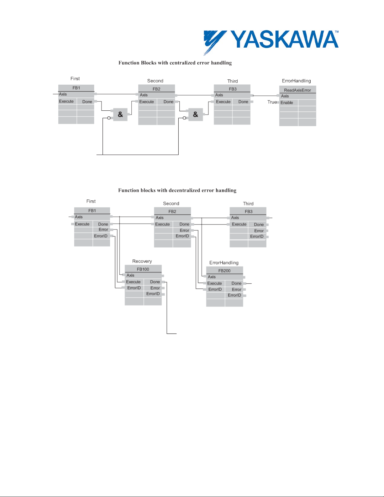
Error Handling
All access to the drive/motion control is via Function Blocks. Internally
these Function Blocks provide basic error checking on the input data.
If the device itself has an error, it can be read using the MC_ReadAxisError
block.
PLCopenPlus Function Blocks for Motion Control 2013-04-13 6
Page 15
PLCopenPlus Function Blocks for Motion Control 2013-04-13 7
Page 16

Rule applies to
Rule
Output exclusivity
When 'Execute' is true, the outputs ‘Busy’,
Output status
The 'Done', 'InGear', 'InSync', 'InVelocity',
Missing input
According to IEC 61131-3, if any parameter of a
Function block interface
General rules
The following table provides general rules about the interface of the Motion
Control function blocks.
‘Done’, ‘Error’, and ‘CommandAborted’ are
mutually exclusive.
'Error', 'ErrorID' and 'CommandAborted' output s
are reset with the falling edge of
'Execute'. However, the falling edge of 'Execute'
does not stop or even influence the execution of
the actual FB. The corresponding outputs are
set for at least one cycle if the situation occurs,
even if execute was reset before the FB
completed. If an instance of a FB receives a
new 'Execute' before it finishes (as a series of
Input parameters The parameters are read at the rising edge of
commands on the same instance), the FB won’t
return any feedback, like ‘Done’ or
‘CommandAborted’, for the previous action.
the 'Execute' input. To modify any parameter, it
is necessary to change the input parameter(s)
and trigger the 'Execute' again.
parameters
PLCopenPlus Function Blocks for Motion Control 2013-04-13 8
function block input is missing (“open”) then the
Page 17

value from the previous invocation of this
instance will be used. In the first invocation the
Sign rules
The 'Velocity', 'Acceleration', 'Deceleration' and
Error Handling
All blocks have two outputs , whic h dea l w ith
Error: Rising edge of 'Error' indicates that an
'Done', 'InVelocity', 'InGear', and 'InSync'
default value is applied .
Position versus
distance
Behavior
'Position' is a value defined within a coordinate
system. 'Distance' is a relative measure, the
difference between two positions.
'Jerk' are always positive values. 'Position' and
'Distance' can be positive or negative.
errors that can occur while executing that
Function Block. These outputs are defined as
follow:
error occurred during the execution of the
Function Block.
ErrorID: Error number - see the Error Code List
at the end of the manual.
indicate successful completion, so these signals
are logically exclusive to “Error”.
Types of errors:
• Function Block Error (e.g. parameters out of
range, state machine violation attempted)
• Communication Error
• Amplifier/Axis Error
Instance errors do not always result in an axis
error (forcing the axis to 'StandStill'). The error
outputs of the relevant FB are reset with falling
PLCopenPlus Function Blocks for Motion Control 2013-04-13 9
Page 18

edge of 'Execut e' .
Inputs exceeding
If a FB is commanded with parameters which
Behavior of Done
output
Behavior of
CommandAborted
output
The “Done” output (as well as 'InGear',
'InSync', ..) is set when the commanded action
has been completed successfully. With multiple
Function Blocks working on the same axis in a
sequence, the following applies:
When one movement on an axis is interrupted
with another movement on the same axis
without having reached the final goal, 'Done' of
the first FB will not be set.
'CommandAborted' is set when a commanded
motion is interrupted by another motion
command. The reset-behavior of
'CommandAborted' is like that of 'Done'. When
'CommandAborted' occurs, the other outputsignals such as 'InVelocity' are reset.
application limits
result in a violation of application limits, the
instance of th e FB generates an error. The
consequences of this error for the axis are
application specific and thus should be handled
by the application program.
Behavior of Busy
output
'Busy' output indicates that the FB is not
finished. 'Busy' is SET at the rising edge of
'Execute' and RESET when one of the outputs
'Done', 'Aborted', or ' Error' is set. It is
recommended that this FB should be kept in the
active loop of the application program for at
least as long as ‘Busy’ is true, because the
PLCopenPlus Function Blocks for Motion Control 2013-04-13 10
Page 19

outputs may still change. For one axis, several
Function Blocks might be busy, but only one can
Output ‘Active’
The 'Active' output is available on Function
Enable and Valid
The 'Enable' input is coupled to a 'Valid' output.
be active at a time. Exceptions are
'MC_SuperImposed' and 'MC_Phasing', where
more than one FB related to one axis can be
active.
Blocks with buffering capabilities. This output is
set at the moment the function block takes
control of the axis. For unbuffered mode the
outputs “Active” and “Busy” can have the same
value.
Status
'Enable' is level sensitive, and 'Valid' shows that
a valid set of outputs is available at the FB. The
'Valid' output is TRUE as long as a valid output
value is available and the 'Enable' input is
TRUE. The relevant output values are refreshed
while the input 'Enable' is TRUE. If there is a FB
error, the output is not valid (“Valid” set to
FALSE). When the error condition disappears,
the values will reappear and 'Valid' output will
be set again.
PLCopenPlus Function Blocks for Motion Control 2013-04-13 11
Page 20

The behavior of the “Execute” / “Done” style FBs is as follows:
Why the command input is edge sensitive
The “Execute” input always triggers the function with its rising edge. New
input values may be commanded during execution of a previous command
because the inputs are only read once. The 'Done' output can be used to
trigger the next part of the movement. The example given below is
intended to explain the behavior of the Function Block execution.
PLCopenPlus Function Blocks for Motion Control 2013-04-13 12
Page 21

The figure illustrates the sequence of three Function Blocks, 'First',
'Second' and 'Third', controlling the same axis. These three Function
Blocks could be for instance various absolute or relative move
commands. When “First” has completed, the output 'First.Done' triggers
'Second.Execute'. The output 'Second.Done' AND “In13” trigger
'Third.Execute'.
PLCopenPlus Function Blocks for Motion Control 2013-04-13 13
Page 22

Example 1: Same Function Block instance controls different motions of an axis
The figure below shows an example where the Function Block FB1 is used
to control “AxisX” with three different values of Velocity. In a Sequential
Function Chart (SFC) the velocity 10, 20, and 0 is assigned to V. To trigger
the Execute input with a rising edge the variable E is stepwise set and
reset.
PLCopenPlus Function Blocks for Motion Control 2013-04-13 14
Page 23

PLCopenPlus Function Blocks for Motion Control 2013-04-13 15
Page 24

Example 2: Different FB instances control the motions of an axis
Different instances related to the same axis can control the motions on an
axis. Each instance will then be responsible for one part of the global
profile.
PLCopenPlus Function Blocks for Motion Control 2013-04-13 16
Page 25

PLCopenPlus Function Blocks for Motion Control 2013-04-13 17
Page 26

Aborting Versus Buffered Modes: Input BufferMode
Buffer mode
Short description Im portant
descriptions!
Input value at
Aborting
This is the Default mode. The FB
immediately.
INT#0
Buffered
The FB affects the axis as soon as
between the movements.
INT#1
BlendingLow
The FB controls the axis after the
INT#2
Some of the FBs provide the input 'BufferMode'. By setting this input, the
FB can either be run in "non-buffered mode" (default behavior) or in
buffered mode. The transition behavior (blending) between two motions
can be set by defining when the FB starts its action. The difference
between these two modes is as follows:
A Function Block in non-buffered mode is applied immediately, even
when this interrupts a motion which is currently executed.
A Function Block in buffered mode is not executed until the current
FB has finished the motion it is currently executing and indicates this
by setting the corresponding output (Done or InPosition or InVelocity see table below).
Up to 16 motion blocks can be buffered before error 4369 would be
generated. Axis Parameter 1600 indicates the number of buffered
motion blocks.
Possible options for the buffered mode
The input BufferMode must be connected with a INT data type which can
have the following values:
note: The meaning of each value
BufferMode *
may vary depending on the
FB(s) involved. For this reason,
please also refer to the
individual parameter
aborts an ongoing motion and the
command affects the axis
the previous movement is
complete. The axis will stop
PLCopenPlus Function Blocks for Motion Control 2013-04-13 18
Page 27

previous FB has finished, but the
axis will not stop between the
commands.
BlendingPrevious
The FB controls the axis after the
velocity of the previous move.
INT#3
of this (next) function.
(next) function.
movements. The velocity is blended
with the lowest velocity of both
previous FB has finished
(equivalent to buffered), but the
axis will not stop between the
movements. Blending with the
BlendingNext The FB controls the axis after the
previous FB has finished, but the
axis will not stop between the
movements. Blending with velocity
BlendingHigh The FB controls the axis after the
previous FB has finished
(equivalent to buffered), but the
axis will not stop between the
movements. Blending with highest
velocity of the previous and this
INT#4
INT#5
PLCopenPlus Function Blocks for Motion Control 2013-04-13 19
Page 28

Example 1: Standard behavior of 2 following absolute movements
PLCopenPlus Function Blocks for Motion Control 2013-04-13 20
Page 29

Example 2: Aborting motion
PLCopenPlus Function Blocks for Motion Control 2013-04-13 21
Page 30

Example 3: Buffered motion
PLCopenPlus Function Blocks for Motion Control 2013-04-13 22
Page 31

Example 4: BlendingLow motion
PLCopenPlus Function Blocks for Motion Control 2013-04-13 23
Page 32

Example 5: BlendingPreviou s motion
PLCopenPlus Function Blocks for Motion Control 2013-04-13 24
Page 33

Example 6: BlendingNext motion
PLCopenPlus Function Blocks for Motion Control 2013-04-13 25
Page 34

Example 7: BlendingHi gh motion
PLCopenPlus Function Blocks for Motion Control 2013-04-13 26
Page 35

Rules for the definition of Motion Control function blocks according to PLCopen
The input/output variables of the function blocks mandatory according to
the PLCopen Standard are marked with the letter 'B' in the defined tables
in the definition of the function blocks.
Input/output variables marked with the letter 'E' are optional, i.e. they can
be implemented but are not mandatory.
Vendor specific input / output variables, i.e. added by the vendor, are
marked with the letter 'V'.
According to the IEC 61131-3 specification, the input variables may be
unconnected or not parameterized by the user. In this case, the function
block will use the value from the previous invocation of the function block
instance, or in case of the first invocation, the initial value will be used.
PLCopenPlus Function Blocks for Motion Control 2013-04-13 27
Page 36

Page 37

Data Types
Data Types
A data type can be any simple or complex set of data consisting of multiple data types.
The following data types are supplied by Yaskawa as part of the PLCopenPlus firmware
library and will appear in the project tree when a new project is created. The DataType
file is named below.
PLCopenPlus Function Blocks for Motion Control 2013-04-13 29
Page 38

Data Type: AXIS_REF
The AXIS_REF data type identifies an axis and thus provides the interface
to the hardware or virtual axes. AXIS_REF is used as VAR_IN_OUT in all
Motion Control Function Blocks described in this Online help. It is
represented as an input and an output connected by a horizontal line in
the graphical representation of a function block.
The value of AxisNum is determined by the logical axis number assigned in
the Hardware Configuration. See the Configuration tab under each axis.
Data Type Declaration
TYPE
AXIS_REF:STRUCT
AxisNum:UINT;
END_STRUCT;
END_TYPE
Variable Declaration Example
PLCopenPlus Function Blocks for Motion Control 2013-04-13 30
Page 39

Code Example
AxisX.Number:=UINT#0;
MCMoveAbsoluteX(Axis:=AxisX, Execute:=FALSE);
AxisX:=MCMoveAbsolutX.Axis;
AxisY.Number:=UINT#0;
MCMoveAbsoluteY(Axis:=AxisY, Execute:=FALSE);
AxisX:=MCMoveAbsolutY.Axis;
PLCopenPlus Function Blocks for Motion Control 2013-04-13 31
Page 40

Data Type: CONTINUOUS_REF
This datatype is for use with the Y_ProbeContinuous function block
Data Type Declaration
CONTINUOUS_LATCH_RECORD : STRUCT
ValueCyclic : LREAL; (* Cyclic latch value (rotary
modulus)*)
ValueNonCyclic : LREAL; (* Non-cyclic latch value *)
InputID : INT; (* Input signal ID corresponding
to the latch data
Indicates C-Channel, EXT1,
EXT2, EXT3 *)
PatternIndex : UINT; (* Signal pattern array index *)
PatternCount : UINT; (* Signal pattern repeat count
*)
Reserved : UINT;
END_STRUCT;
LATCH_BUFFER_TYP : ARRAY(0..127) OF CONTINUOUS_LATCH_RECORD
CONTINUOUS_REF : STRUCT
BufferSize : UINT; (* Maximum number of
registration marks that will be
tracked by the application at
any one time *)
BufferLevel : UINT; (* Number of registration marks
in the buffer and
not yet processed by the
application *)
PLCopenPlus Function Blocks for Motion Control 2013-04-13 32
Page 41

StorePointer : UINT; (* Array index of the
LATCH_BUFFER_TYP last stored by
Y_ProbeContinuous *)
UsePointer : UINT; (* Array index of the next
LATCH_BUFFER_TYP to be
used by the application *)
Buffer : LATCH_BUFFER_TYP; (* Array of continuous latch
data *)
END_STRUCT;
PLCopenPlus Function Blocks for Motion Control 2013-04-13 33
Page 42

Data Type: INPU T_REF
This datatype is for use with the MC_ReadDigitalInput function block
Data Type Declaration
TYPE
(* Inputs and outputs are referenced via a variable of the
type INPUT_REF or OUTPUT_REF *)
INPUT_REF: STRUCT
ID: UINT; (* Mapping may be required for drive
inputs and C-pulse. These inputs must not been neglected *)
END_STRUCT;
END_TYPE
Variable Declaration Example
PLCopenPlus Function Blocks for Motion Control 2013-04-13 34
Page 43

Code Example
PLCopenPlus Function Blocks for Motion Control 2013-04-13 35
Page 44

Data Type: OUTPUT_REF
This data type is for use with the MC_WriteDigitalOutput function block.
Data Type Declaration
TYPE
(* Inputs and outputs are referenced via a variable of the
type INPUT_REF or OUTPUT_REF *)
OUTPUT_REF: STRUCT
ID: UINT; (* The user may output to memory or
hardware. *)
END_STRUCT;
END_TYPE
Variable Declaration Example
PLCopenPlus Function Blocks for Motion Control 2013-04-13 36
Page 45

Code Example
PLCopenPlus Function Blocks for Motion Control 2013-04-13 37
Page 46

Data Type: PAT TERN_REF
This datatype is for use with the Y_ProbeContinuous function block
Data Type Declaration
PATTERN_ARRAY_TYP : ARRAY(0..7) OF UINT;
PATTERN_REF : STRUCT
PatternSize : UINT; (* Number of sensors that will
operate in a repeating
pattern. Sent to Sigma-5 Pn850
*)
PatternCount : UINT; (* Number of times the pattern
repeats until the FB
will be done. UINT#0 =
infinite. Sent to Sigma-5
Pn 851 *)
PatternArray : PATTERN_ARRAY_TYPE;
(* Array of signal ID pattern,
indicating C Channel,
EXT1, EXT2, EXT3. Sent to Sigma5 Pn853 and Pn854 *)
END_STRUCT;
PLCopenPlus Function Blocks for Motion Control 2013-04-13 38
Page 47

Data Type: PrmStruct
This datatype is for use with the Y_ReadMultipleParameters function block
Data Type Declaration
Params : STRUCT
Number : UINT; (* The parameter number to read *)
Reserved : UDINT;
Value : LREAL; (* The value of the parameter *)
END_STRUCT;
ParamList : ARRAY[0..99] OF Params;
PrmStruct : STRUCT
LastParam : INT; (* Indicates the last parameter
in the list *)
Reserved : UDINT;
ParamData : ParamList; (* The array of parameter numbers
and values *)
END_STRUCT;
PLCopenPlus Function Blocks for Motion Control 2013-04-13 39
Page 48

Data Type: RTC_STRUCT
This datatype is for use with the Y_SetRTC function block
Data Type Declaration
RTC_Struct:STRUCT
Year:INT;
Month:INT;
Day:INT;
Hour:INT;
Minute:INT;
Second:INT;
Millisecond:INT;
END_STRUCT;
PLCopenPlus Function Blocks for Motion Control 2013-04-13 40
Page 49

Data Type: TRIGGER_REF
This data type is for use with the MC_TouchProbe and MC_AbortTrigger
function blocks.
Data Type Declaration
TYPE
(* MC_TouchProbe requires a trigger referenced via a variable
of the type TRIGGER_REF *)
Detection_Pattern:(Rising_Edge, Falling_Edge); (* Not
used *)
TRIGGER_REF: STRUCT
Input: INPUT_REF;
Bit: UINT;
Pattern:
ID: UINT; (* Unique identification of the trigger;
used for MC_AbortTrigger *)
END_STRUCT;
END_TYPE
DETECTION_PATTERN;
PLCopenPlus Function Blocks for Motion Control 2013-04-13 41
Page 50

Variable Declaration Example
The following chart details the correct values for the TRIGGER_REF
structure based on the hardware latch to be detected.
Code Example
PLCopenPlus Function Blocks for Motion Control 2013-04-13 42
Page 51

Data Type: Y_DISENGAGE_DATA
This data type is for use with the Y_CamOut function block.
Data Type Declaration
TYPE
Y_Disengage_Data : STRUCT
EndMode : INT; (* Possible values are
described in Y_DisengageMethod *)
RampOut : INT; (* Reserved for future use *)
RampOutData1 : LREAL; (* Reserved for future use *)
RampOutData2 : LREAL; (* Reserved for future
use *)
RampOutData3 : LREAL; (* Reserved for future
use *)
RampOutData4 : LREAL; (* Reserved for future
use *)
END_STRUCT;
END_TYPE;
Y_DisengageMethod: (AtPosition, Immediate, EndOfProfile);
(* Immediate and EndofProfile Reserved for
future use *)
PLCopenPlus Function Blocks for Motion Control 2013-04-13 43
Page 52

Data Type: Y_ENGAGE_DATA
This data type is for use with the Y_CamIn function block.
Data Type Declaration
TYPE
Y_Engage_Data : STRUCT
StartMode : INT; (* Possible values are
described in Y_EngageMethod *)
MasterRelative : BOOL;
SlaveAbsolute : BOOL;
RampIn : INT; (* Reserved for future use
*)
RampInData1 : LREAL; (* Reserved for future use
*)
RampInData2 : LREAL; (* Reserved for future use
*)
RampInData3 : LREAL; (* Reserved for future use
*)
RampInData4 : LREAL; (* Reserved for future use
*)
END_STRUCT;
END_TYPE;
Y_EngageMethod: (AtPosition, Immediate, Linked);
PLCopenPlus Function Blocks for Motion Control 2013-04-13 44
Page 53

Data Type: Y_MS_CAM_STRUCT
This data type is for use with the Y_CamStructSelect, Y_ReadCamTable,
and Y_WriteCamTable function blocks. Y_MS_CAM_STRUCT consists of
the sub-structures found below. Refer to the Internally Created Cam Data
diagram in the Cam Data Management section.
Data Type Declaration
TYPE
Y_CAM_HEADER:STRUCT
TableType:INT; (* INT#1 = Master/Slave
pair *)
Reserved1:UINT;
DataSize:UDINT; (* Size of cam table in bytes.
There are 16 bytes
(8 Master/8 Slave)per
Y_MS_PAIR. For example, if
your CAM profile has 360
data pairs, then the data
size is 360 pairs x 16 bytes =
5760 bytes *)
END_STRUCT;
Y_MS_PAIR: STRUCT
Master:LREAL; (* Master position *)
Slave:LREAL; (* Slave position *)
END_STRUCT;
PLCopenPlus Function Blocks for Motion Control 2013-04-13 45
Page 54

Y_MS_HEADER:STRUCT
SlaveIncremental:BOOL;
MasterIncremental:BOOL;
Reserved1:UINT;
Reserved2:UINT;
Reserved3:UINT;
END_STRUCT;
MS_Array_Type:ARRAY[0..512] OF Y_MS_PAIR;
Y_MS_CAM_STRUCT:STRUCT
Header:Y_CAM_HEADER;
MS_Header:Y_MS_HEADER;
MS_Data:MS_Array_Type;
END_STRUCT;
END_TYPE
PLCopenPlus Function Blocks for Motion Control 2013-04-13 46
Page 55

Enumerated Types
Some blocks accept an enumerated type, which is a keyword (or constant)
representing a value which will configure the operation of the function
block. Enumerated types are equivalent to zero-based
integers. Therefore, the first value equates to zero, the second to 1,
etc. The format for enumerated types is as follows: ENUM:(0, 1, 2...) as
displayed in the example below (MC_BufferMode#Aborting).
MC_BufferMode:(Aborting, Buffered, BlendingLow, BlendingPrevious,
BlendingNext, BlendingHigh)
MC_Detection_Pattern: (Rising_Edge, Falling_Edge)
MC_Direction: (Positive_Direction, Shortest_Way, Negative_Direction,
Current_Direction)
(* MC_Direction#ShortestWay and MC_Direction#Current_Direction are
designed for use in applications where the Load Type is configured as a
rotary or modularized axis. Additionally, MC_Direction#Current_Direction
only applies if an existing move is in progress and another function block
such as MC_MoveAbsolute or MC_MoveRela tive is executed. Once the axis
PLCopenPlus Function Blocks for Motion Control 2013-04-13 47
Page 56

is at StandStill, using MC_Direction_CurrentDirection will default to the
positive direction. *)
MC_SwitchMode:(On, Off, EdgeOn, EdgeOff, EdgeSwitchPositive,
EdgeSwitchNegative) (* Only MC_SwitchMode#EdgeOn is supported *)
Y_AdjustMode: (MasterDistance, ElapsedTime, WithinRange)
• If AdjustMode=Y_AdjustMode#MasterDistance, then the cam
adjustment starts immediately, and completes when the master has
travelled the specified distance. If MasterDistance is 0.0, then the cam
adjustment finishes in the same scan it starts.
• If AdjustMode=Y_AdjustMode#ElapsedTime, then the cam adjustment
starts immediately, and completes within the specified time. If time=0 .0 ,
then the adjustment completes in the same scan it starts.
• If AdjustMode=Y_AdjustMode#WithinRange, then the cam adjustment
starts when the master is crosses the StartPosition, and completes when
the master reaches the EndPosition. If the master position is already
between StartPosition and EndPosition, then the adjustment starts
immediately, but still completes at the EndPosition, which means that the
correction speeds may be higher.
Y_RampIn:(None, Accel, SCurve) - Reserved for future use.
Y_RampOut: Reserved for future use.
Y_EngageMethod:(AtPosition, Immediate, Linked): This enumerated type
is reserved for Y_CamIn
Y_DisengageMethod:(AtPosition, Immediate, EndOfProfile): This
enumerated ty pe is reserved for Y_CamOut
PLCopenPlus Function Blocks for Motion Control 2013-04-13 48
Page 57

Function Block List
Function Block
Support
Short
Single-Axis Motion Function Blocks
MC_AccelerationProfile
None
Commands an
MC_GroupSyncOut
None
Function Block List
This online help provides information about the function blocks which can
be used for motion control. The function blocks are divided into single-axis
and multi-axis motion blocks and administrative function blocks which do
not generate a movement.
Single-Axis Motion Function Blocks
Single-Axis Administrative Function Blocks
Multi-Axis Motion Function Blocks
Multi-Axis Administrative Function Blocks
Homing Function Blocks
description
activation of a
positioning task
as an array which
describes the
acceleration of an
axis depending on
the time.
MC_Halt Future
PLCopenPlus Function Blocks for Motion Control 2013-04-13 49
Page 58

MC_Home
None
Obsolete function
MC_MoveAbsolute
Ver. 1.0
Commands a
MC_MoveAdditive
Future
Commands a
MC_MovePath
None
block. Please
use Part 5
Homing Function
Blocks to perform
Homing Functions
(i.e. MC_Step...)
controlled motion
of the axis at a
specified absolute
position.
MC_MoveContinuous Future
MC_MoveRelative Ver. 1.0 Commands a
controlled motion
of a specified
relative distance
additional to the
original
commanded
position in the
discrete motion
state.
controlled motion
of a specified
distance relative
to the actual
PLCopenPlus Function Blocks for Motion Control 2013-04-13 50
Page 59

position at the
time of the
MC_MoveVelocity
Ver. 1.0
Commands a
MC_PathGearIn
None
MC_PositionProfile
Future
Commands an
MC_TorqueControl
Ver. 1.0
execution.
MC_MoveSuperImposed Ver. 1.0 Commands a
controlled motion
of a specified
relative distance
additional to an
existing motion.
never ending
controlled motion
at a specified
MC_Stop Ver. 1.0 Commands a
velocity.
controlled motion
stop of an axis.
activation of a
positioning task
as an array which
describes the
positions of an
axis depending on
the time.
MC_VelocityProfile Future Commands an
activation of a
PLCopenPlus Function Blocks for Motion Control 2013-04-13 51
Page 60

positioning task
Y_HoldPosition
Ver. 1.0.5.1
Puts the servo in
Single-Axis Administrative Function Blocks
MC_AbortTrigger
Ver. 1.0
Aborts function
MC_Power
Ver. 1.0
Sets or resets the
MC_ReadActualTorque
Ver. 1.0
Reads the actual
as an array which
describes the
velocity of an axis
depending on the
time.
position mode and
freezes the
profiler.
blocks which are
connected to
trigger events.
MC_DigitalCamSwitch Refer to the
PLCopen Toolbox
available on
www.yaskawa.com
Provides output
control based on
a position input
and speed.
enabling for an
axis.
MC_ReadActualPosition Ver. 1.0 Reads the actual
position of the
axis.
torque of the axis.
MC_ReadActualVelocity Ver. 1.0 Reads the actual
PLCopenPlus Function Blocks for Motion Control 2013-04-13 52
velocity of the
Page 61

axis.
MC_ReadBoolParameter
Ver. 1.0
Reads the axis
MC_ReadDigitalInput
Future
Function block not
MC_ReadParameter
Ver. 1.0
Reads the axis
MC_SetOverride
Future
Sets the values of
MC_ReadAxisError Ver. 1.0 Indicates an axis
error and allows
to read the error.
parameters of the
data type BOOL.
necessary to read
inputs.
MC_ReadDigitalOutput Future Function block not
necessary to set
outputs.
MC_ReadStatus Ver. 1.0 Returns the status
MC_Reset Ver. 1.0 Acknowledges an
parameters.
of the axis with
respect to the
motion currently
in progress.
existing error
message.
override for the
whole axis, and
all functions that
are working on
PLCopenPlus Function Blocks for Motion Control 2013-04-13 53
that axis.
Page 62

MC_SetPosition
Ver. 1.0
Sets the current
MC_TouchProbe
Ver. 1.0
Record an axis
MC_WriteBoolParameter
Ver. 1.0
Writes the axis
MC_WriteDigitalOutput
Future
Writes a value to
Y_DirectControl
Ver. 1.0.7.4
Allows direct
position of an axis
to a new position
and thus shifts
the coordinate
system.
position at a
trigger event.
parameters of the
data type BOOL.
MC_WriteParameter Ver. 1.0 Writes the axis
Y_ClearAlarms Ver. 1.0 Clears non-axis-
the output
referenced by the
argument
'Output'. Function
block not
necessary to write
outputs.
parameters.
related controller
alarms
access to any of
PLCopenPlus Function Blocks for Motion Control 2013-04-13 54
three possible
control modes
Page 63

available on the
Y_ReadAlarm
Ver. 1.0
Reads non-axis-
Y_ReadDriveParameter
Ver. 1.0.5.1
Reads a
Y_VerifyParameters
Ver. 1.1
Compares
Y_WriteDriveParameter
Ver. 1.0.5.1
Writes a
Multi-Axis Motion Function Blocks
MC_GearIn
Ver. 1.0
Activates an
MECHATROLINK
network servo
control system.
related controller
alarms
parameter from
the associated
motor driver
parameters in the
drive with those
stored in the
controller
parameter from
the associated
motor driver
Y_WriteParameters Ver. 1.1 Sends parameters
stored in the
controller to the
drive
electronic velocity
PLCopenPlus Function Blocks for Motion Control 2013-04-13 55
gearing between
a slave and
Page 64

master axis.
MC_GroupHome
None
MC_MoveCircularAbsolute
None
MC_MoveDirectAbsolute
None
MC_MoveDirectRelative
None
MC_MoveLinearRelative
None
MC_MovePositionDirectRelative
None
MC_GearInPosition Ver. 1.0 Commands a gear
ratio between the
position of the
slave and master
axes from the
synchronization
point onwards.
MC_GearOut Ver. 1.0 Deactivates the
electronic velocity
gearing between
a slave and
master axis.
MC_GroupHalt None
MC_GroupStop None
MC_MoveCircularRelative None
MC_MoveLinearAbsolute None
MC_MovePathSynchronized None
MC_Phasing Future Creates a phase
shift in the master
PLCopenPlus Function Blocks for Motion Control 2013-04-13 56
position of a slave
axis.
Page 65

MC_TrackConveyorBelt
None
MC_TrackRotaryTable None
Y_CamFileSelect
Ver. 1.1
Y_CamOut
Ver. 1.1
Deactivates the
Y_CamScale
Ver. 1.1
Multiplication
Y_CamShift
Ver. 1.1
Y_ReleaseCamTable
Ver. 1.1
Frees motion
Y_CamIn Ver. 1.1 Activates the
coupling between
master and slave
axis.
coupling of the
slave axis with
the master axis.
factor applied to
the slave data
Y_CamStructSelect Ver. 1.1 Loads cam data
from the
application
program into
motion memory
Y_ReadCamTable Ver. 1.1 Copies cam data
from motion
memory into the
application
program
memory and
PLCopenPlus Function Blocks for Motion Control 2013-04-13 57
CamTableID
Page 66

Y_ResetMechatrolink
Ver. 1.0.5.1
Restarts the
MECHATROLINK
Multi-Axis Administrative Function Blocks
MC_AddAxisToGroup
None
MC_CamTableSelect
None
See
MC_GroupDisable
None
MC_GroupReadActualAcceleration
None
MC_GroupReadActualVelocity
None
MC_GroupReadConfiguration
None
MC_GroupReadStatus
None
MC_GroupSetOverride
None
MC_PathSelect
None
MC_RemoveAxisFromGroup
None
network
Y_SlaveOffset Ver. 1.1 Adds an offset to
the slave data
Y_WriteCamTable Ver. 1.1 Copies cam data
from the
application
program to the
motion memory
MC_GroupEnable None
MC_GroupReadActualPosition None
MC_GroupReadError None
MC_GroupReset None
MC_GroupSetPosition None
Y_CamTableSelect
PLCopenPlus Function Blocks for Motion Control 2013-04-13 58
Page 67

MC_SetCartesianTransform
None
MC_SetCoordinateTransform None
MC_SetDynCoordTransform
None
MC_SyncAxisToGroup
None
Homing Function Blocks
MC_AbortPassiveHoming
Future
MC_StepAbsolute
None
This function is
MC_StepAbsSwitch
Future
MC_StepDirect
Future
MC_StepLimitSwitch
Ver. 1.0
Performs homing
MC_StepReferenceFlyingSwitch
Future
MC_SetKinTransform None
MC_UngroupAllAxes None
MC_FinishHoming Ver. 1.0 Transfers an axis
from 'Homing'
state to
'Standstill' state.
not required with
Yaskawa absolute
encoders.
MC_StepBlock Future
by searching for a
limit switch.
MC_StepReferenceFlyingRefPulse Future
MC_StepRefPulse Ver. 1.0 Performs homing
by searching for a
Zero pulse.
PLCopenPlus Function Blocks for Motion Control 2013-04-13 59
Page 68

Page 69

Function Blocks for Motion Control
Parameter
Data type
Description
B
Axis
AXIS_REF
Logical axis reference. This value
E
TriggerInput
TRIGGER_REF
Reference to the trigger signal
MC_AbortTrigger
The Function Block aborts function blocks which are associated with trigger
events (e.g. MC_TouchProbe).
Parameters
VAR_IN_OUT
can be located on the Configuration
tab in the Hardware Configuration
(logical axis number).
PLCopenPlus Function Blocks for Motion Control 2013-04-13 61
Page 70

source. See MC_TouchProbe
VAR_INPUT Default
B
Execute
BOOL
Upon the rising
FALSE
VAR_OUTPUT
B
Done
BOOL
Set high when the commanded
B
Busy
BOOL
Set high upon the rising edge of the
B
Error
BOOL
Set high if error has occurred during
edge, all other
function block inputs
are read and the
function is initiated.
To modify an input,
change the value
and re-trigger the
execute input.
action has been completed
successfully. If another block takes
control before the action is
completed, the Done output will not
be set. This output is reset when
execute goes low.
'Execute' or 'Enable' input, and
reset if Done, CommandAborted, or
Error is true.
the execution of the function block.
This output is cleared when
'Execute' or 'Enable' goes low.
E ErrorID UINT If error is true, this output provides
PLCopenPlus Function Blocks for Motion Control 2013-04-13 62
the Error ID. This output is reset
Page 71

when 'Execute' or 'Enable' goes low.
ErrorID
Meaning
4391
The function block can not be used with a virtual axis.
4625
Axis ID does not correspond to an axis configured on the
4630
Trigger or pattern reference is not valid
57620
The structure size does not match.
Notes
The following chart details the correct values for the TRIGGER_REF
structure based on the hardware latch to be detected.
Related Function Blocks
MC_TouchProbe
Error Description
0 No Error
system. Verify the value of AxisNum matches a logical axis
number in the configuration. Tip: Make sure AXIS_REF is
properly declared as a VAR or VAR_GLOBAL in all relevant
POUs.
PLCopenPlus Function Blocks for Motion Control 2013-04-13 63
Page 72

Example
The following example shows how MC_AbortTrigger cancels (Aborts) a
busy MC_TouchProbe.
Timing Diagram for MC_AbortTrigger
PLCopenPlus Function Blocks for Motion Control 2013-04-13 64
Page 73

MC_FinishHoming
VAR_IN_OUT
This FB transfers an axis from the ‘Homing’ state to the ‘StandStill’ state.
It does not perform any movement. This block is necessary after the user
builds a homing procedure containing any number of MC_StepXXXX
homing blocks (See Notes ).
Parameters
Parameter Data type Description
B Axis AXIS_REF Logical axis reference. This value can be locate d on the
Configuration tab in the Hardware Confi g uration (logical axis
number).
VAR_INPUT Default
B Execute BOOL Upon the rising edge, all other
function block inputs are read and
the function is initiated. To modify
an input, change the value and
re-trigger the execute input.
False
PLCopenPlus Function Blocks for Motion Control 2013-04-13 65
Page 74

VAR_OUTPUT
E
ErrorID
UINT
If error is true, this output provides the Error ID. This outp ut is
E BufferMode MC_BufferMode Defines the behavior of the axis -
allowable modes are Aborting,
Buffered, BlendingLow,
BlendingPrevious, BlendingNext,
and BlendingHigh.MC_BufferMode#Aborting
MC_BufferMode#Buffered
MC_BufferMode#BlendingLow
MC_BufferMode#BlendingPrevious
MC_BufferMode#BlendingNext
MC_BufferMode#BlendingHigh
B Done BOOL Set high when the commanded action has been completed
successfully. If another block takes control before the action is
completed, the Done output will not be set. This outp ut is rese t
when execute goes low.
E Busy BOOL Set high upon the rising edge of the 'Execute' or 'Enable' input,
and reset if Done, CommandAborted, or Error is true.
E Active BOOL For buffered modes, this output is set high at the moment the
block takes control of the axis. For non buffered modes, the
outputs Busy and Active have the same value.
E CommandAborted BOOL Set high if motion is aborted by another motion command or
MC_Stop. This output is cleared with the same behav ior as the
Done output.
B Error BOOL Set high if error has occurred during the execution of the
function block. This output is cleared w hen 'Exec ute ' or 'Enable'
goes low.
MC_BufferMode#Aborting
Notes
This block is not necessary if the last homing block executed is
MC_StepRefPulse, MC_StepDirect, or MC_StepAbsolute because these
blocks will change the motion state back to 'Standstill' when complete.
This block is only necessary if the following homing blocks are last in a
homing sequence:
• MC_StepAbsSwitch
PLCopenPlus Function Blocks for Motion Control 2013-04-13 66
reset when 'Execute' or 'Enable' goes low.
Page 75

• MC_StepLimitSwitch
ErrorID
Meaning
0
No Error
4378
The function block is not applicable for the external axis
4381
Motion aborted due to axis alarm.
4893
The specified external axis may not be used. A physical axis is
57620
The structure size does not match.
• MC_StepBlock.
Error Description
specified
4625 Axis ID does not correspond to an axis configured on the
system. Verify the value of AxisNum matches a logical axis
number in the configuration. Tip: Make sure AXIS_REF is
properly declared as a VAR or VAR_GLOBAL in all relevant
POUs.
4641 Buffer mode does not correspond to a valid enumeration value.
required
PLCopenPlus Function Blocks for Motion Control 2013-04-13 67
Page 76

MC_GearIn
Parameter
Data type
Description
B
Slave
AXIS_REF
A logical reference to the slave axis
B
Execute
BOOL
Upon the rising edge, all other
FALSE
This Function Block commands a velocity ratio between the master and
slave axes. If the gearing mode is executed while the master is already in
motion, position synchronization will not be achieved unless some other
method (MC_MoveSuperimposed or MC_GearInPos) is employed.
Parameters
VAR_IN_OUT
B Master AXIS_REF A logical reference to the master axis
VAR_INPUT Default
function block inputs are read and
the function is initiated. To modify
an input, change the value and
PLCopenPlus Function Blocks for Motion Control 2013-04-13 68
Page 77

re-trigger the execute input.
B
RatioNumerator
DINT
Gear ratio numerator
DINT#0
VAR_OUTPUT
B
InGear
BOOL
Set high upon successful completion of the functio n. Thi s output
B
Error
BOOL
Set high if error has occurred during the execution of the
E
ErrorID
UINT
If error is true, this output provides the Error ID. This outp ut is
B RatioDenominator DINT Gear ratio denominator DINT#1
E Acceleration LREAL Value of the acceleration in user
units/second^2 (acceler ation is
applicable with same sign of
torque and velocity)
E Deceleration LREAL Value of the deceleration in user
units/second^2 (deceleration is
applicable with opposite signs of
torque and velocity)
E Jerk LREAL Value of the Jerk [u/s3]. Value o f
the jerk in user units/second^3.
Jerk not supported . Reserved for
future use.
E BufferMode MC_BufferMode D e fines the behavior of the axis -
allowable modes are Aborting,
Buffered, BlendingLow,
BlendingPrevious, BlendingNext,
and BlendingHigh.MC_BufferMode#Aborting
MC_BufferMode#Buffered
MC_BufferMode#BlendingLow
MC_BufferMode#BlendingPrevious
MC_BufferMode#BlendingNext
MC_BufferMode#BlendingHigh
LREAL#0.0
LREAL#0.0
LREAL#0.0
MC_BufferMode#Aborting
E Busy BOOL Set high upon the rising edge of the 'Execute' or 'Enable' input,
E Active BOOL For buffered modes, this output is set high at the moment the
E CommandAborted BOOL Set high if motion is aborted by another motion command or
PLCopenPlus Function Blocks for Motion Control 2013-04-13 69
is reset when execute goes low.
and reset if Done, CommandAborted, or Error is true.
block takes control of the axis. For non buffered modes, the
outputs Busy and Active have the same value.
MC_Stop. This output is cleared with the same behav ior as the
Done output.
function block. This output is cleared w hen 'Exec ute ' or 'Enable'
goes low.
reset when 'Execute' or 'Enable' goes low.
Page 78

Notes
ErrorID
Meaning
0
No Error
1. The slave accelerates up to the ratio of the master velocity and become
"InGear" when ratio is reached. Compensation for any position
relationship lost during the acceleration phase is not provided during
synchronization. Use MC_GearInPos when maintaining a position
relationship is important.
2. The gearing ratio can be changed while MC_GearIn is running, using a
consecutive MC_GearIn command or re-triggering the 'Execute' input
without the necessity to MC_GearOut first.
3. The InGear output is set the first time the specified ratio is reached.
Related Function Blocks
MC_GearOut: disengages the Slave axis from the master axis.
Error Description
4369 The move could not be buffered because the axis motion
queue is full. 16 moves is the maximum which can be
buffered.
4370 The move could not be started because motion is prohibited.
MC_Stop.Execute might be held high, preventing motion. If
MC_Stop has control of the axis, no other function block can
override the "Stopping" state. Other blocks that try to cause
motion while MC_Stop has control of the axis will generate
this error. Also verify that the limit switches are not active by
checking the Global Variables for the axis. Also, a motion
PLCopenPlus Function Blocks for Motion Control 2013-04-13 70
Page 79

block may be attempting to abort an MC_TorqueControl
move.
4378
The function block is not applicable for the external axis
4381
Motion aborted due to axis alarm.
4641
Buffer mode does not correspond to a valid enumeration
4659
Acceleration is less than or equal to zero.
4666
Denominator is zero.
4891
The slave axis can not be the same as the master axis.
57620
The structure size does not match.
specified
4625 Axis ID does not correspond to an axis configured on the
system. Verify the value of AxisNum matches a logical axis
number in the configuration. Tip: Make sure AXIS_REF is
properly declared as a VAR or VAR_GLOBAL in all relevant
POUs.
4626 The master slave relationship is defined. A slave cannot be a
master to another axis.
value.
4660 Deceleration is less than or equal to zero.
4667 Jerk is less than or equal to zero
PLCopenPlus Function Blocks for Motion Control 2013-04-13 71
Page 80

Timing Diagram
PLCopenPlus Function Blocks for Motion Control 2013-04-13 72
Page 81

Example
PLCopenPlus Function Blocks for Motion Control 2013-04-13 73
Page 82

MC_GearInPos
This Function Block commands a gear ratio between the master and slave
axes. Position synchronization is achieved over a defined region of travel
for both master and slave.
PLCopenPlus Function Blocks for Motion Control 2013-04-13 74
Page 83

Parameters
VAR_IN_OUT
VAR_INPUT
Default
B
SlaveSyncPosition
LREAL
Slave position at which the axes
LREAL#0.0
E
Jerk
LREAL
Value of the Jerk [u/s3]. Value o f
LREAL#0.0
Parameter Data type Description
B Master AXIS_REF A logical reference to the master axis
B Slave AXIS_REF A logical reference to the slave axis
B Execute BOOL Upon the rising edge, all other
function block inputs are read and
the function is initiated. To modify
an input, change the value and
re-trigger the execute input.
B RatioNumerator DINT Gear ratio numer ator DINT#0
B RatioDenominator DINT Gear ratio denominator DINT#1
B MasterSyncPosition LREAL Master Position at which the axes
are synchronized
are synchronized
E SyncMode INT Reserved for future use INT#0
E MasterStartDistance LREAL Master Distance for
synchronization procedure. See
Note Below
E Velocity LREAL Maximum Velocity allowed by the
slave during 'StartSync' to the
'InSync' event
E Acceleration LREAL Acceleration limit while
attempting to Engage
E Deceleration LREAL Deceleration limit while
attempting to Engage
FALSE
LREAL#0.0
LREAL#0.0
LREAL#0.0
LREAL#0.0
LREAL#0.0
E BufferMode MC_BufferMode Defines the behavior of the axis -
PLCopenPlus Function Blocks for Motion Control 2013-04-13 75
the jerk in user units/second^3.
Jerk not supported . Reserved for
future use.
MC_BufferMode#Aborting
allowable modes are Aborting,
Buffered, BlendingLow,
BlendingPrevious, BlendingNext,
and BlendingHigh.MC_BufferMode#Aborting
MC_BufferMode#Buffered
Page 84

VAR_OUTPUT
E
Busy
BOOL
Set high upon the rising edge of the 'Execute' or 'Enable ' input,
B
CommandAborted
BOOL
Set high if motion is aborted by another motion command or
B
Error
BOOL
Set high if error has occurred during the execution of the
MC_BufferMode#BlendingLow
MC_BufferMode#BlendingPrevious
MC_BufferMode#BlendingNext
MC_BufferMode#BlendingHigh
E StartSync BOOL The slave has started to synchronize, but not yet synchronized
with the master
B InSync BOOL Set high when the slave first synchronizes with the master. This
output is reset when execute goes low.
and reset if Done, CommandAborted, or Error is true.
E Active BOOL For buffered modes, this output is set high at the moment the
block takes control of the axis. For non buffered modes, the
outputs Busy and Active have the same value.
MC_Stop. This output is cleared with the same behav ior as the
Done output.
function block. This output is cleared w hen 'Exec ute ' or 'Enable'
goes low.
E ErrorID UINT If error is true , this outp ut provid e s the Error ID. This output is
reset when 'Execute' or 'Enable' goes low.
Notes
• If the master is stationary when the MC_GearInPos function is
• Only one SyncMode is supported: MC_SyncMode#Acc_Vel_Dec uses
• MasterStartDistance and MasterSyncPosition are in units of the
executed, it will remain busy until motion occurs.
the input parameters Acceleration, Velocity, & Deceleration to make
a move to the SlaveSyncPosition. The slave may attain
synchronization early if these parameters are set higher than
optimally required. If these parameters will not allow the slave to
engage by the time the master reached the MasterSyncPosition, an
error will result.
specified master.
PLCopenPlus Function Blocks for Motion Control 2013-04-13 76
Page 85

MasterDistance is a relative distance from the desired
ErrorID
Meaning
4369
The move could not be buffered because the axis motion
4370
The move could not be started because motion is prohibited.
4378
The function block is not applicable for the external axis
4625
Axis ID does not corresp ond to an axis configured on the
4626
The master slave relationship is defined. A slave cannot be a
•
synchronization point. The slave will start the synchronization
process when the master is within this range of the
MasterSyncPosition.
Error Description
0 No Error
queue is full. 16 moves is the maximum which can be
buffered.
MC_Stop.Execute might be held high, preventing motion. If
MC_Stop has control of the axis, no other function block can
override the "Stopping" state. Other blocks that try to cause
motion while MC_Stop has control of the axis will generate
this error. Also verify that the limit switches are not active by
checking the Global Variables for the axis. Also, a motion
block may be attempting to abort an MC_TorqueControl
move.
specified
4381 Motion aborted due to axis alarm.
system. Verify the value of AxisNum matches a logical axis
number in the configuration. Tip: Make sure AXIS_REF is
properly declared as a VAR or VAR_GLOBAL in all relevant
POUs.
PLCopenPlus Function Blocks for Motion Control 2013-04-13 77
Page 86

master to another axis.
4641 Buffer mode does not correspond to a valid enumeration
4659
Acceleration is less than or equal to zero.
4660
Deceleration is less than or equal to zero.
4669
Engage position is outside the cam table domain.
57620
The structure size does not match.
value.
4647 The synch mode does not correspond to a valid enumeration
value.
4657 Distance parameter is less than or equal to zero.
4666 Denominator is zero.
4889 The engage phase exceeded the distance limit. Slave axis
could not attain the target position and velocity within the
user specified master distance.
4891 The slave axis can not be the same as the master axis.
PLCopenPlus Function Blocks for Motion Control 2013-04-13 78
Page 87

Usage Matrix Chart
Examples
Scenario 22:
A logic analyzer plot of the commanded position (Prm 1010) of the master
and the slave before and after' InSync' in is shown below.
PLCopenPlus Function Blocks for Motion Control 2013-04-13 79
Page 88

Scenario 30:
A logic analyzer plot of the commanded position (Prm 1010) of the master
and the slave before and after' InSync' in is shown below.
Recall that the requirements for this scenario state that the
MasterStartDistance and the MasterSyncDistance must be negative.
PLCopenPlus Function Blocks for Motion Control 2013-04-13 80
Page 89

PLCopenPlus Function Blocks for Motion Control 2013-04-13 81
Page 90

Timing Diagram
PLCopenPlus Function Blocks for Motion Control 2013-04-13 82
Page 91

MC_GearOut
Parameter
Data
Description
B
Slave
AXIS_REF
A logical reference to the slave axis
VAR_OUTPUT
This Function Block disengages the Slave axis from the Master axis. The
slave will continue to move at the last commanded velocity.
Parameters
Type
VAR_IN_OUT
VAR_INPUT Default
B Execute BOOL Upon the rising edge, all other func tio n blo ck inp uts are
read and the function is initiated. To modify an input,
change the value and re-trigger the execute input.
B Done BOOL Set high when the commanded action has been completed
successfully. If another block takes control before the action is
completed, the Done output will not be set. This outp ut is reset when
execute goes low.
E Busy BOOL Set high upon the rising edge of the 'Execute' or 'Enable' input, and
reset if Done, CommandAborted, or Error is true.
B Error BOOL Set high if error has occurred during the execution of the function
block. This output is cl e ared when 'Exe c ute ' or 'Enable ' goes low .
E ErrorID UINT If error is true, this output provides the Error ID. This outp ut is res e t
FALSE
PLCopenPlus Function Blocks for Motion Control 2013-04-13 83
Page 92

when 'Execute' or 'Enable' goes low.
ErrorID
Meaning
4378
The function block is not applicable for the external axis
4381
Motion aborted due to axis alarm.
4625
Axis ID does not correspond to an axis configured on the
4376
The master slave relationship can not be modified because the
4404
Can not execute MC_GearOut because axis is not in gear
Notes
It is assumed that this command is followed by another command, for
instance MC_Stop, MC_GearIn, or any other command. If there is no new
command, the defa ult con dit ion wi ll be to ma intain the la st gea red v eloc ity.
Related Function Blocks
MC_GearIn: Commands a velocity ratio between the master and slave
axes.
Error Description
0 No Error
specified
system. Verify the value of AxisNum matches a logical axis
number in the configuration. Tip: Make sure AXIS_REF is
properly declared as a VAR or VAR_GLOBAL in all relevant
POUs.
master axis has not been set yet.
57620 The structure size does not match.
PLCopenPlus Function Blocks for Motion Control 2013-04-13 84
Page 93

Example
In the example shown below, an MC_Stop function block is used to bring
the slave axis to a standstill after the gear relation is broken using
MC_GearOut
PLCopenPlus Function Blocks for Motion Control 2013-04-13 85
Page 94

VAR_IN_OUT
B
Axis
AXIS_REF
Logical axis reference. This value can be locate d on the Config ur a tio n
VAR_INPUT
Default
MC_MoveAbsolute
This Function Block commands a controlled motion to the specified
absolute position.
Parameters
Parameter Data Type Description
tab in the Hardware Configuration (logical ax is numb er ).
B Execute BOOL Upon the rising edge, all other
function block inputs are read and
the function is initiated. To modify
an input, change the value and
re-trigger the execute input.
FALSE
PLCopenPlus Function Blocks for Motion Control 2013-04-13 86
Page 95

E
Deceleration
LREAL
Value of the deceleration in user
LREAL#0.0
E
Direction
MC_Direction
Specifies the direction of motion.
MC_Direction#Positive_Direction
VAR_OUTPUT
B Position LREAL A po s itive or negative value
within the coordinate system in
user units.
E Velocity LREAL Absolute value of the velocity in
user units/second
E Acceleration LREAL Value of the acceleration in user
units/second^2 (acceler ation is
applicable with same sign of
torque and velocity)
units/second^2 (deceleration is
applicable with opposite signs of
torque and velocity)
E Jerk LREAL Value of the Jerk [u/s3]. Value o f
the jerk in user units/second^3.
Jerk not supported . Reserved for
future use.
Allowable modes are
positive_direction, s hor test_way,
negative_direction,
current_direction.
MC_Direction#Positive_Direction
MC_Direction#Shortest_Way
MC_Direction#Negative_Direction
MC_Direction#Current_Direction
E BufferMode MC_BufferMode Defines the behavior of the axis -
allowable modes are Aborting,
Buffered, BlendingLow,
BlendingPrevious, BlendingNext,
and BlendingHigh.MC_BufferMode#Aborting
MC_BufferMode#Buffered
MC_BufferMode#BlendingLow
MC_BufferMode#BlendingPrevious
MC_BufferMode#BlendingNext
MC_BufferMode#BlendingHigh
LREAL#0.0
LREAL#0.0
LREAL#0.0
LREAL#0.0
MC_BufferMode#Aborting
B Done BOOL Set high when the commanded action has been completed successfully.
E Busy BOOL Set high upon the rising edge of the 'Execute' or 'Enable' input, and
PLCopenPlus Function Blocks for Motion Control 2013-04-13 87
If another block takes control before the actio n is comp le ted, the Done
output will not be set. This output is reset when execute goes low.
reset if Done, CommandAborted, or Error is true.
Page 96

E Active BOOL For buffered modes, this output is set high at the moment the block
takes control of the axis. For non buffered modes, the outputs Bus y
and Active have the same value.
E CommandAborted BOOL Set high if motion is aborted by another motion command or MC_Stop.
This output is cleared with the same behavior as the Done output.
B Error BOOL Set high if error has occurred during the execution of the function
block. This output is cleared when 'Execute ' or 'Enable ' goes low .
E ErrorID UINT If error is true, this output provides the Error ID. This output is reset
when 'Execute' or 'Enable' goes low.
Notes
• The absolute position, as with all other inputs, can be updated while in
motion by retriggering the Execute input.
• This action completes with velocity zero if no further blocks are pending.
• Regarding the use of the 'Direction' input:
• If there is only one mathematical solution to reach the commanded
position (like in linear systems), the value of the input Direction is
ignored.
• For rotary axis - valid absolute position values are in the range of the
machine cycle. It is possible to specify a relative move of more than one
machine cycle using MC_MoveRelative. When motion is complete, the
position will be reported as somewhere between 0 and machine cycle.
• The Enum type MC_Direction#Shortest_Way will cause motion through
the shortest route. The controller will decide based on the current
position when the function block is executed.
• For further information about the Done output, Profile Complete, and
Motion Complete, see the Determining when motion is complete section.
PLCopenPlus Function Blocks for Motion Control 2013-04-13 88
Page 97

Error Description
ErrorID
Meaning
4369
The move could not be buffered because the axis motion
4378
The function block is not applicable for the external axis
4381
Motion aborted due to axis alarm.
4659
Acceleration is less than or equal to zero.
4660
Deceleration is less than or equal to zero.
4641
Buffer mode does not correspond to a valid enumeration
0 No Error
queue is full. 16 moves is the maximum which can be
buffered.
4370 The move could not be started because motion is prohibited.
MC_Stop.Execute might be held high, preventing motion. If
MC_Stop has control of the axis, no other function block can
override the "Stopping" state. Other blocks that try to cause
motion while MC_Stop has control of the axis will generate
this error. Also verify that the limit switches are not active by
checking the Global Variables for the axis. Also, a motion
block may be attempting to abort an MC_TorqueControl
move.
specified
4625 Axis ID does not corresp ond to an axis configured on the
system. Verify the value of AxisNum matches a logical axis
number in the configuration. Tip: Make sure AXIS_REF is
properly declared as a VAR or VAR_GLOBAL in all relevant
POUs.
4658 Velocity parameter is less than or equal to zero.
PLCopenPlus Function Blocks for Motion Control 2013-04-13 89
Page 98

value.
4642 Direction does not correspond to a valid enumeration value.
4667
Jerk is less than or equal to zero
4893
The specified external axis may not be used. A physical axis is
57617
Instance object is NULL.
57620
The structure size does not match.
4378 The function block is not applicable for the external axis
specified
4369 The move could not be buffered because the axis motion
queue is full. 16 moves is the maximum which can be
buffered.
4381 Motion aborted due to axis alarm.
required
Example
PLCopenPlus Function Blocks for Motion Control 2013-04-13 90
Page 99

Timing Diagram
PLCopenPlus Function Blocks for Motion Control 2013-04-13 91
Page 100

MC_MoveRelative
VAR_IN_OUT
B
Axis
AXIS_REF
Logical axis reference. This value can be locate d on the
This Function Block commands a controlled motion of the specified
distance relative to the commanded position at the time of the execution.
Parameters
Parameter Data type Description
Configuration tab in the Hardware Confi g uration (logical axis
number).
VAR_INPUT Default
B Execute BOOL Upon the rising edge, all other
function block inputs are read and
the function is initiated. To modify
an input, change the value and
re-trigger the execute input.
B Distance LREAL Incremental d is tance (in us er
units)
FALSE
LREAL#0.0
PLCopenPlus Function Blocks for Motion Control 2013-04-13 92
 Loading...