


Yard-Man YM26SS User Manual

Operator’s Manual
IMPORTANT: Read safety rules and instructions carefully before operating equipment.
NOTE: For users on U.S. Forest Land and in the states of California, Maine, Oregon and Washington. All U.S. Forest Land and the
state of California (Public Resources Codes 4442 and 4443), Oregon and Washington require, by law that certain internal combustion
engines operated on forest brush and/or grass-covered areas be equipped with a spark arrestor, maintained in effective working order,
or the engine be constructed, equipped and maintained for the prevention of fire. Check with your state or local authorities for
regulations pertaining to these requirements. Failure to follow these requirements could subject you to liability or a fine. This unit is
factory equipped with a spark arrestor. If it requires replacement, accessory part #753-04121 Spark Arrestor Screen is available by
contacting the service department at 550 N. 54th STREET, CHANDLER, AZ 85226-2434.
MTD SOUTHWEST INC 550 N. 54TH STREET, CHANDLER, ARIZONA 85226-2434
PRINTED IN U.S.A. Rev1
PART NO. 769-00307 (05/02)
English
Straight Shaft,
4-Cycle Trimmer
Model
YM26SS

2
TABLE OF CONTENTS
Content . . . . . . . . . . . . . . . . . . . . . . . . . . . . . . . . . . . . . . . . . . . . . . . . . . . . . . . . . . Page
Rules for Safe Operation . . . . . . . . . . . . . . . . . . . . . . . . . . . . . . . . . . . . . . . . . . . . . 4
Know Your Trimmer . . . . . . . . . . . . . . . . . . . . . . . . . . . . . . . . . . . . . . . . . . . . . . . . . 8
Adjusting the J-Handle . . . . . . . . . . . . . . . . . . . . . . . . . . . . . . . . . . . . . . . . . . . . . . 9
Oil and Fuel Information . . . . . . . . . . . . . . . . . . . . . . . . . . . . . . . . . . . . . . . . . . . . . . 10
Starting/Stopping Instructions . . . . . . . . . . . . . . . . . . . . . . . . . . . . . . . . . . . . . . . . . 11
Operating Instructions . . . . . . . . . . . . . . . . . . . . . . . . . . . . . . . . . . . . . . . . . . . . . . . 13
Maintenance and Repair Instructions . . . . . . . . . . . . . . . . . . . . . . . . . . . . . . . . . . . 15
Cleaning and Storage . . . . . . . . . . . . . . . . . . . . . . . . . . . . . . . . . . . . . . . . . . . . . . . 25
Troubleshooting . . . . . . . . . . . . . . . . . . . . . . . . . . . . . . . . . . . . . . . . . . . . . . . . . . . . 26
Specifications . . . . . . . . . . . . . . . . . . . . . . . . . . . . . . . . . . . . . . . . . . . . . . . . . . . . . . 27
Warranty . . . . . . . . . . . . . . . . . . . . . . . . . . . . . . . . . . . . . . . . . . . . . . . . . . . . . . . . . . 29
FINDING MODEL NUMBER
This Operator’s Manual is an important part of your new trimmer. It will help you assemble, prepare, and
maintain the unit for best performance. Please read and understand what it says.
Before you start assembling your new equipment, please locate the model plate on the unit
and copy the information from it to the space provided below. The information on the model
plate is very important if you need help from our Customer Support Department or an authorized
dealer.
• You can locate the model number by looking on the underside of the engine. A sample model plate is
explained below. For future reference, please copy the model number and the serial number of the
equipment in the space below.
CALLING CUSTOMER SUPPORT
If you have difficulty assembling this product or have any questions regarding the controls, operation or
maintenance of this unit, please call the Customer Support Department.
Call 1- (800)-345-8746, or in Canada 1- (800)-668-1238, to reach a Customer Support
representative. Please have your unit’s model number and serial number ready when you call.
See previous section to locate this information. You will be asked to enter the serial number in
order to process your call.
VISIT OUR WEB SITE
Visit our web site at www.yardman.com for more information about our quality Yard Man products, customer
service, parts, tips, literature and more.
Copy the model / parent
part number here:
Copy the serial number here:

SPARK ARRESTOR
NOTE: For users on U.S. Forest Land and in the states of California, Maine, Oregon and Washington. All
U.S. Forest Land and the state of California (Public Resources Codes 4442 and 4443), Oregon and Washington
require, by law that certain internal combustion engines operated on forest brush and/or grass-covered areas be
equipped with a spark arrestor, maintained in effective working order, or the engine be constructed, equipped
and maintained for the prevention of fire. Check with your state or local authorities for regulations pertaining to
these requirements. Failure to follow these requirements could subject you to liability or a fine. This unit is
factory equipped with a spark arrestor. If it requires replacement, ask your LOCAL SERVICE dealer to install
the accessory part #753-04121 Spark Arrestor.
WARNING!
Read the Operator’s Manual(s) and follow all warnings and safety instructions. Failure to do so
can result in serious injury to the operator and/or bystanders.
FOR QUESTIONS, CALL 1-800-345-8746 IN U.S. OR
1-800-668-1238 in CANADA
The purpose of safety symbols is to attract your attention to possible dangers. The safety
symbols and their explanations deserve your careful attention and understanding. The safety
warnings do not by themselves eliminate any danger. The instructions or warnings they give are
not substitutes for proper accident prevention measures.
SAFETY ALERT SYMBOL: Indicates danger, warning, or caution. Attention is required in order to
avoid serious personal injury. May be used in conjunction with other symbols or pictographs.
NOTE: Advises you of information or instructions vital to the operation or maintenance of the equipment.
DANGER: Failure to obey a safety warning will result in serious injury to yourself or to others.
Always follow the safety precautions to reduce the risk of fire, electric shock and personal
injury.
WARNING: Failure to obey a safety warning can result in injury to yourself and others. Always
follow the safety precautions to reduce the risk of fire, electric shock and personal injury.
CAUTION: Failure to obey a safety warning may result in property damage or personal injury to
yourself or to others. Always follow the safety precautions to reduce the risk of fire, electric
shock and personal injury.
SECTION 1: RULES FOR SAFE OPERATION
3

READ ALL INSTRUCTIONS
WARNING: When using the unit the safety
rules must be followed. For your own safety
and that of bystanders please read these
instructions before operating the unit.
Please keep the instructions safe for later
use.
BEFORE OPERATING
• Read this operating instruction manual carefully. Be
thoroughly familiar with the controls and the proper
use of the equipment. Know how to stop the unit and
disengage the controls quickly.
• Do not operate this unit when tired, ill, or under the
influence of alcohol, drugs, or medication.
• Never allow children to operate the equipment. Never
allow adults unfamiliar with the instructions to use the
unit. Never allow adults to operate the equipment
without proper instruction.
• Children and teens under the age of 15 must not use
the unit, except for teens guided by an adult.
• Inspect the unit before use. Replace damaged parts.
Check for fuel leaks. Make sure all fasteners are in
place and secure. Replace cutting attachment parts
that are cracked, chipped, or damaged in any way.
Make sure the cutting attachment is properly installed
and securely fastened. Be sure the cutting attachment
shield is properly attached, and positioned as
recommended. Failure to so can result in personal
injury to the operator and bystanders, as well as
damage to the unit.
• Use only 0.080 inch (2.03 mm) diameter genuine
manufacturer’s replacement line. Never use metalreinforced line, wire, chain, or rope, etc. These can
break off and become dangerous projectiles.
• Be aware of the risk of injury to the head, hands and
feet.
• Clear the area to be cut before each use. Remove all
objects such as rocks, broken glass, nails, wire, or
string which can be thrown or become entangled in
the cutting attachment. Clear the area of children,
bystanders and pets. At a minimum, keep all children,
bystanders and pets outside a 50 feet (15 m) radius;
there still may be a risk to bystanders from thrown
objects. Bystanders should wear eye protection. If you
are approached, stop the engine and cutting
attachment immediately.
• Squeeze the throttle control and check that it returns
automatically to the idle position. Make all
adjustments or repairs before using unit.
• Be sure the cutting attachment is not in contact with
anything before starting the unit.
• This unit was not designed to be used as a brushcutter.
Do not attach or operate this unit with any type of
brushcutting blade or brushcutting attachment.
SAFETY WARNINGS FOR GAS
TRIMMERS
WARNING: Gasoline is highly flammable, and its vapors
can explode if ignited. Take the following precautions:
• Store fuel only in containers specifically designed and
approved for the storage of such materials.
• Always stop the engine and allow it to cool before
filling the fuel tank. Never remove the cap of the fuel
tank, or add fuel, while the engine is hot. Never
operate the unit without the fuel cap securely in place.
Loosen the fuel tank cap slowly to relieve any
pressure in the tank.
• Add fuel in a clean, well-ventilated area outdoors
where there are no sparks or flames. Slowly remove
the fuel cap only after stopping engine. Do not smoke
while fueling or mixing fuel. Wipe up any spilled fuel
from the unit immediately.
• Avoid creating a source of ignition for spilled fuel. Do
not start the engine until fuel vapors dissipate.
• Move the unit at least 30 feet (9.1 m) from the fueling
source and site before starting the engine. Do not
smoke. Keep sparks and open flames away from the
area while adding fuel or operating the unit.
WHILE OPERATING
• Never start or run the unit inside a closed room or
building. Breathing exhaust fumes can kill. Operate
this unit only in a well ventilated area outdoors.
• Wear safety glasses or goggles that are marked as
meeting ANSI Z87.1 standards, and ear/hearing
protection when operating this unit. Wear a face or
dust mask if the operation is dusty.
• Wear heavy, long pants, boots, gloves and a long
sleeve shirt. Do not wear loose clothing, jewelry, short
pants, sandals, or go barefoot. Secure hair above
shoulder level.
• The cutting attachment shield must always be in place
while operating the unit. Do not operate unit without
both trimming lines extended, and the proper line
installed. Do not extend the trimming line beyond the
length of the shield.
• This unit has a clutch. The cutting attachment remains
stationary when the engine is idling. If it does not, have
the unit adjusted by any nonroad engine repair
establishment, individual or authorized service dealer.
• Adjust the J-handle to your size to provide the best
grip.
SECTION 1: RULES FOR SAFE OPERATION
4

• Be sure the cutting attachment is not in contact with
anything before starting the unit.
• Use the unit only in daylight or good artificial light.
• Avoid accidental starting. Be in the starting position
whenever pulling the starter rope. The operator and
unit must be in a stable position while starting. See
Starting/Stopping Instructions.
• Use the right tool. Use this tool only for the purpose
intended.
• Do not overreach. Always keep proper footing and
balance.
• Always hold the unit with both hands when operating.
Keep a firm grip on both the front and rear handle or
grips.
• Keep hands, face and feet at a distance from all
moving parts. Do not touch or try to stop the cutting
attachment while it is rotating.
• Do not touch the engine, gear housing, or muffler. These
parts get extremely hot from operation and remain hot
for a short time after turning the engine off.
• Do not operate the engine faster than the speed
needed to cut, trim, or edge. Do not run the engine at
high speed when not cutting.
• Always stop the engine when cutting is delayed or
while walking from one cutting location to another.
• If you strike or become entangled with a foreign object,
stop the engine immediately and check for damage. Do
not operate before repairing damage. Do not operate
the unit with loose or damaged parts.
• Stop and switch the engine to OFF for maintenance,
repair, or for changing the cutting attachment or other
attachments.
• Use only replacement parts and accessories approved
by the manufacturer for this unit. These are available
from your authorized service dealer. Use of any non
approved parts or accessories could lead to serious
injury to the user, or damage to the unit, and void your
warranty.
• Keep unit clean of vegetation and other materials.
They may become lodged between the cutting
attachment and shield.
•To reduce fire hazard, replace faulty muffler and spark
arrestor, keep the engine and muffler free from grass,
leaves, excessive grease or carbon build up.
OTHER SAFETY WARNINGS
• Never store the unit, with fuel in the tank, inside a
building where fumes may reach an open flame or
spark.
• Allow the engine to cool before storing or
transporting. Be sure to secure the unit while
transporting.
• Store the unit in a dry area, locked up or up high
to prevent unauthorized use or damage, out of the
reach of children.
• Never douse or squirt the unit with water or any other
liquid. Keep handles dry, clean and free from debris.
Clean after each use. See Cleaning and Storage
Instructions.
• Keep these instructions. Refer to them often and use
them to instruct other users. If you loan someone this
unit, also loan them these instructions.
SAVE THESE INSTRUCTIONS
SECTION 1: RULES FOR SAFE OPERATION
5

6
SECTION 1: RULES FOR SAFE OPERATION
SAFETY AND INTERNATIONAL SYMBOLS
This operator's manual describes safety and international symbols and pictographs that may appear on this product.
Read the operator's manual for complete safety, assembly, operating and maintenance and repair information.
SYMBOL MEANING
• SAFETY ALERT SYMBOL
Indicates danger, warning, or caution. May be used in conjunction with other
symbols or pictographs.
•WARNING - READ OPERATOR'S MANUAL
Read the Operator’s Manual(s) and follow all warnings and safety instructions.
Failure to do so can result in serious injury to the operator and/or bystanders.
• WEAR EYE AND HEARING PROTECTION
WARNING:
Thrown objects and loud noise can cause severe eye injury and hearing loss.
Wear eye protection meeting ANSI Z87.1-1989 standards and ear protection when
operating this unit. Use a full face shield when needed.
• KEEP BYSTANDERS AWAY
WARNING:
Keep all bystanders, especially children and pets, at least 50 feet (15 m.)
from the operating area.
• PRIMER BULB
Push primer bulb, fully and slowly, 5 to 7 times.
• UNLEADED FUEL
Always use clean, fresh unleaded fuel.
• OIL
Refer to operator's manual for the proper type of oil.

7
SYMBOL MEANING
• THROWN OBJECTS AND ROTATING CUTTER CAN CAUSE SEVERE INJURY
WARNING: Do not operate without the cutting attachment shield in place.
Keep away from the rotating cutting attachment.
•ON/OFF STOP CONTROL
ON / START / RUN
•ON/OFF STOP CONTROL
OFF OR STOP
• HOT SURFACE WARNING
Do not touch a hot muffler or cylinder. You may get burned. These parts get
extremely hot from operation. When turned off they remain hot for a short time.
• SHARP BLADE
WARNING: Sharp blade on cutting attachment shield. To prevent serious injury, do
not touch line cutting blade.
• DO NOT USE METAL BLADES
WARNING: To prevent serious injury, do not attach or operate the unit with any
type of metal blade.
• CHOKE CONTROL
A • FULL choke position.
B • PARTIAL choke position.
C • RUN position.
SECTION 1: RULES FOR SAFE OPERATION
8
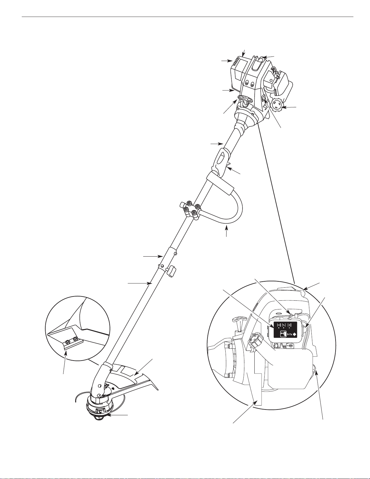
SECTION 2: KNOW YOUR TRIMMER
APPLICATIONS
As a trimmer;
• Cutting grass and light weeds.
• Edging
• Decorative trimming around trees, fences, etc.
Other optional accessories may be used with the
YM26SS. See list of add-ons on page 13.
Cutting Attachment
Shield
Fuel Cap
Throttle
Control
J-Handle
Cutting Attachment
Shaft Grip
Primer Bulb
Choke Lever
Oil Fill Plug / Dipstick
Air Filter Cover
Engine Feet
Spark Plug
On/Off Stop Control
Shaft Housing
Starter Rope Grip
EZ-Link
™
Coupler
Line Cutting Blade
Spark Plug
Muffler
Muffler Guard
Spark Arrestor
9
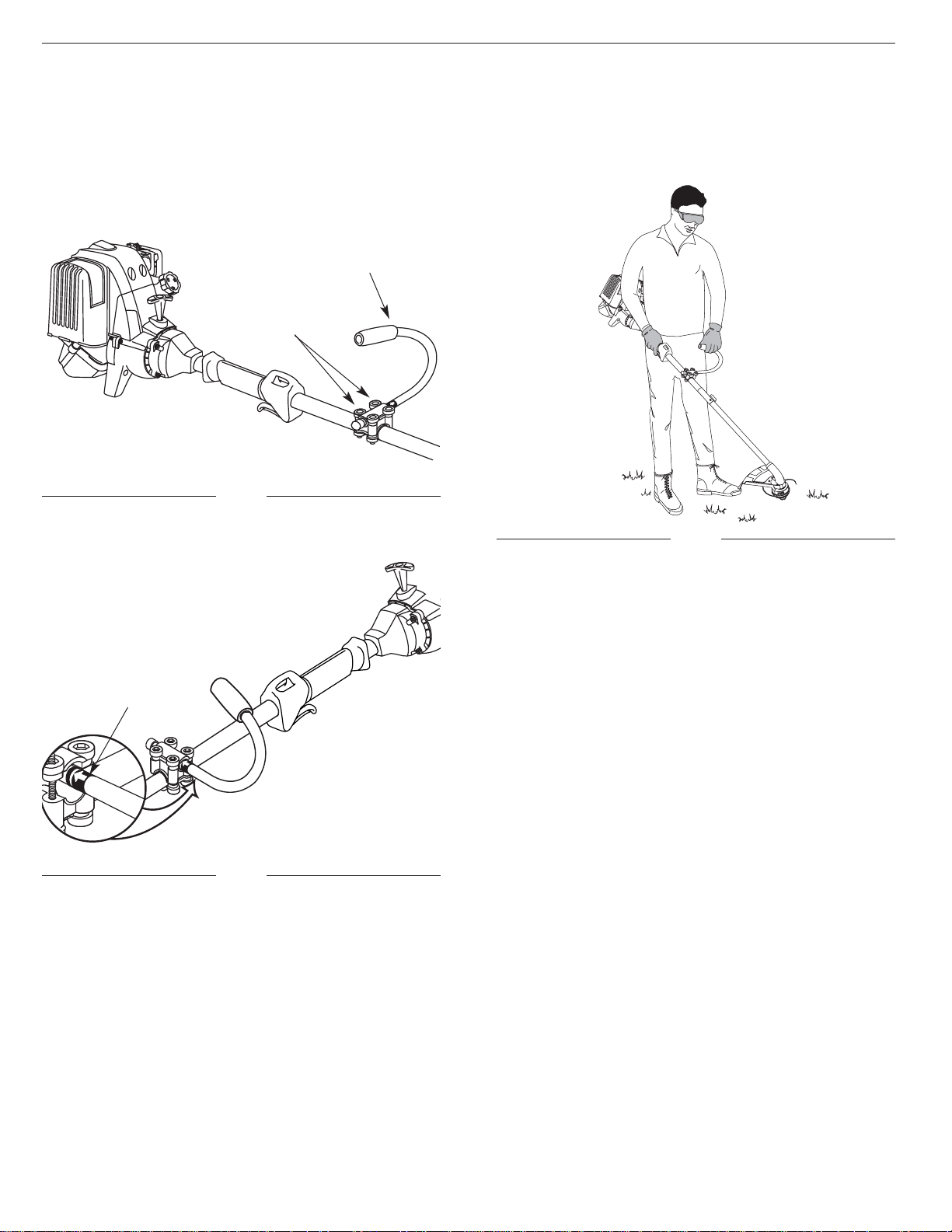
SECTION 3: ADJUSTING THE J-HANDLE
4. Tighten the clamp screws evenly, until the J-handle is
secure.
3. While holding the unit in the operating position
(Fig. 3), position the J-handle to the location
that provides you the best grip.
Decal
ADJUSTING THE J-HANDLE
1. Loosen the four (4) screws holding the J-handle in
place (Fig. 1). Do not completely remove the screws.
(4) Screws
J-Handle
2. Slide the J-handle in or out until the arrow/white line
on the decal touches the clamp assembly (Fig. 2).
Fig. 1
Fig. 2
Fig. 3
10
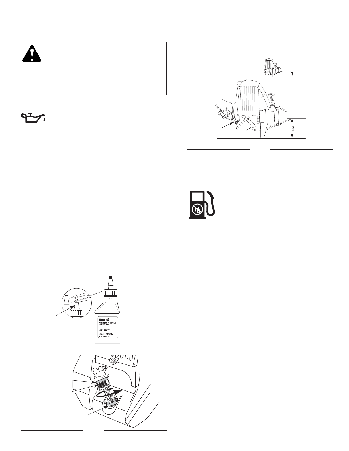
SECTION 4: OIL AND FUEL INFORMATION
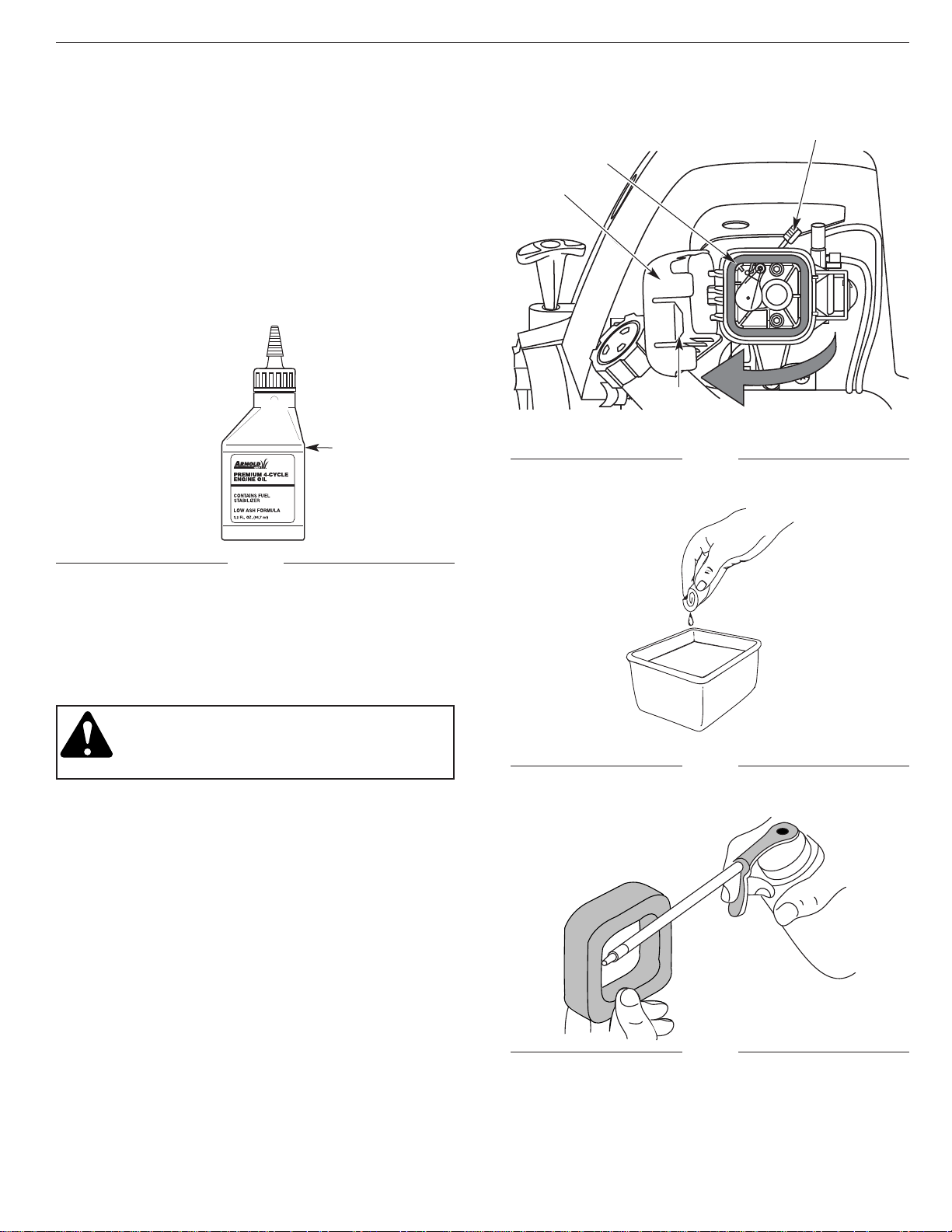
Fig. 4
Funnel Spout
DANGER: OVERFILLING OIL CRANKCASE
MAY CAUSE SERIOUS PERSONAL INJURY!
The importance of checking and maintaining
the proper oil level in the crank case cannot
be overemphasized. Check oil before each
use and change as needed. See Changing
the Oil in the Maintenance and Repair
Instructions section.
RECOMMENDED OIL TYPE
Using the proper type and weight of oil in the
crankcase is extremely important. Check the
oil before each use and change the oil
regularly. Failure to use the correct oil, or
using dirty oil, can cause premature engine wear and
failure.
Use a high-quality SAE 30 weight oil of API (American
Petroleum Institute) service class SF, SG, SH.
ADDING OIL TO CRANKCASE – INITIAL USE
NOTE: This unit is shipped without being filled with oil. In
order to avoid damage to the unit, put oil in the
crankcase before attempting to start unit.
Your unit is supplied with one 3.4 fluid oz. (100 ml.)
bottle of SAE 30 SF, SG, SH oil (Fig. 4).
NOTE: Save the bottle to measure the correct amount
for future oil changes. See Changing the Oil in
the Maintenance and Repair Instructions
section.
1. Unscrew the top of the bottle of oil and remove the
paper seal covering the opening. Replace top. Cut
the tip off the funnel spout (Fig. 4).
2. Place the unit on a flat level surface.
3. Remove the oil plug / dipstick from the crankcase
(Fig. 5).
Fig. 6
Oil Fill
NOTE: Never add oil to the fuel or fuel tank.
5. Wipe up any oil that may have spilled and reinstall
the oil fill plug/dipstick.
4. Pour the entire bottle of oil into the oil fill hole (Fig. 6).
RECOMMENDED FUEL TYPE
Old fuel is the primary reason for the unit not
running properly. Be sure to use fresh, clean,
unleaded gasoline.
NOTE: This is a four cycle engine. In order to avoid
damage to the unit, do not mix oil with
gasoline.
Definition of Blended Fuels
Today's fuels are often a blend of gasoline and
oxygenates such as ethanol, methanol or MTBE (ether).
Alcohol-blended fuel absorbs water. As little as 1%
water in the fuel can ruin the fuel or form acids when
stored. Use fresh fuel (less than 60 days old), when
using alcohol-blended fuel.
Using Blended Fuels
If you choose to use a blended fuel, or its use is
unavoidable, follow recommended precautions.
• Always use fresh unleaded gasoline
• Use the fuel additive STA-BIL
®
or an equivalent.
• Drain tank and run the engine dry before storing unit.
Using Fuel Additives
The use of fuel additives, such as STA-BIL®Gas Stabilizer
or an equivalent, will inhibit corrosion and minimize the
formation of gum deposits. Using a fuel additive can keep
fuel from forming harmful deposits in the carburetor for up
to six (6) months. Add 0.8 oz. (23 ml.) of fuel additive per
gallon of fuel according to the instructions on the
container. NEVER add fuel additives directly to the unit's
gas tank.
Oil Fill Plug/Dipstick
Oil Fill Hole
Fig. 5
O-Ring
11
FUELING UNIT
WARNING: Gasoline is extremely flammable
and its vapors can explode if ignited. To
avoid serious personal injury, always stop the
engine and allow it to cool before filling the
fuel tank. Do not smoke while filling the tank.
Keep sparks and open flames away from the
area.
1. Remove fuel cap (Fig. 7).
WARNING: Remove fuel cap slowly to avoid
injury from
gasoline spray.
Fig. 7
Fuel Cap
Fuel Tank
Gas Can Spout
2. Place spout of gas container into the fill hole on the
fuel tank (Fig. 7) and fill tank.
WARNING: Add gasoline in a clean, well
ventilated area outdoors. Avoid creating a
source of ignition for spilt fuel.
NOTE: Do not overfill tank.
3. Wipe up any gasoline that may have spilled
4. Reinstall the fuel cap.
WARNING: Never operate the unit without
the fuel cap securely in place.
5. Move the unit at least 30 ft. (9.1 m) from the fueling
source and site before starting the engine.
NOTE: Dispose of the old gasoline in accordance to
Federal, State and Local regulations.
Unleaded
Gasoline
SECTION 4: OIL AND FUEL INFORMATION
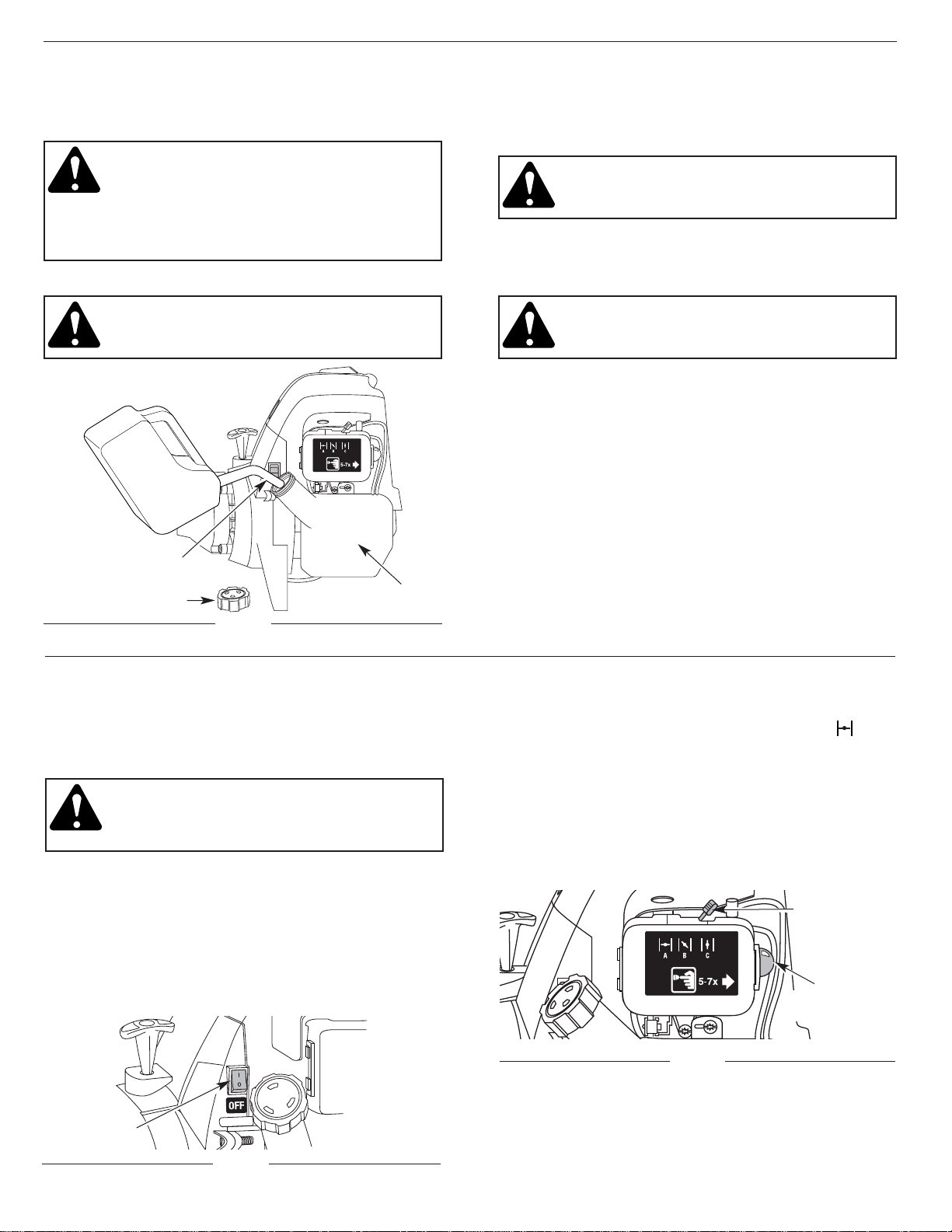
SECTION 5: STARTING/STOPPING INSTRUCTIONS
STARTING INSTRUCTIONS
Cold Start - First Start of the Day or Engine Ran Out
of Fuel
WARNING: Operate this unit only in a well
ventilated area outdoors. Carbon monoxide
exhaust fumes can be lethal in a confined
area.
1. Check oil level in crankcase. See Checking the Oil
Level in the Maintenance and Repair Instructions
section.
2. Fill the fuel tank with fresh, clean, unleaded
gasoline.
3. Put the Start/Stop Engine Control in the START [I]
position (Fig. 8).
Fig. 8
Fig. 9
4. Place the choke lever in the FULL choke (A)
position (Fig. 9).
NOTE: Slide the choke lever directly above the
appropriate symbol on air filter cover decal
(Fig. 9).
5. Fully press and release the primer bulb slowly 7
times. Gasoline should be felt and visible in the bulb
(Fig. 9). If gasoline has not entered the bulb, press
three more times, or until it does.
Start / Stop
Control
Primer
Bulb
Choke
Lever
6. Squeeze the throttle control to the wide open
(full throttle) position.
7. With the unit in the starting position (Fig. 10) pull the
starter rope briskly 5 times in the FULL choke (A)
position. If the engine attempts to run before the fifth
pull, proceed to step 8.
8. Move the choke lever to the PARTIAL (B) position
(Fig. 9).
NOTE: The engine will not run in the FULL choke (A)
position.
9. Pull the starter rope 1 to 3 pulls until the engine
starts. Run for 15-30 seconds. If the unit fails to start
return to step 7.
NOTE: If the outside temperature is below 40˚F (4˚C), run
the unit at full throttle for 30 seconds to one (1)
minute
10. Move the choke lever to the RUN (C) position and
run at full throttle for 30 seconds, and up to one (1)
minute in temperatures below 40˚F (4˚ C).
SECTION 5: STARTING/STOPPING INSTRUCTIONS
WARNING: Avoid accidental starting. Be in
the starting position whenever pulling the
starting rope. To avoid serious personal
injury, the operator and unit must be in a
stable position while starting.
Fig. 10
11. Release the throttle control to the idle position and
begin operation.
NOTE: If the engine does not start using these
procedures, repeat steps 5 through 11 using
TWO (2) pulls in the FULL choke (A) position.
Engine Re-Start - Warm Engine With Fuel
1. Put the Start/Stop Engine Control in the START [I]
position (Fig. 8).
2. Move the choke lever to the PARTIAL (B) position
(Fig. 9).
3. Fully press and release the primer bulb slowly 7
times. Gasoline should be felt and visible in the bulb
(Fig. 9). If gasoline has not entered the bulb, press
three more times, or until it does.
4. Squeeze the throttle control to the wide open
(full throttle) position.
5. With the unit in the starting position (Fig. 10), pull the
starter rope briskly until the engine starts.
6. When the engine starts, move the choke lever to the
RUN (C) position, and run at full throttle for 30
seconds, and up to one (1) minute in temperatures
below 40˚F (4˚ C).
NOTE: If the engine does not start using the Engine
Re-start procedures, revert to the Cold Start
procedures earlier in this section.
NOTE: 4-stroke engines, like cars, are able to start in the
idle position. As an alternate method, you may
want to start your unit in the idle position when
the unit is warm. With the Start/Stop control in
the START position, pull the starter rope briskly.
When the engine starts, run at full throttle for 30
seconds. If the unit fails to start or dies, revert to
the Engine Re-Start proceedure.
STOPPING INSTRUCTIONS
1. Release your hand from the throttle control (Fig. 10).
Allow the engine to idle.
2. To stop the engine, put the Start/Stop Engine
Control in the STOP [O] position (Fig. 8).
Starter Rope
Throttle Control
12
OPERATING THE EZ-LINK™SYSTEM
The EZ-Link™system enables the use of these
optional add-ons.
Blower/Vacuum . . . . . . . . . . . . . . . . . . . . . . . . . . BV720r
Cultivator . . . . . . . . . . . . . . . . . . . . . . . . . . . . . . GC720r
Edger . . . . . . . . . . . . . . . . . . . . . . . . . . . . . . . . . . LE720r
Hedge Trimmer . . . . . . . . . . . . . . . . . . . . . . . . . . HS720r
Snow Thrower . . . . . . . . . . . . . . . . . . . . . . . . . . . ST720r
Straight Shaft Trimmer . . . . . . . . . . . . . . . . . . . . SS725r
Sweeper/Blower . . . . . . . . . . . . . . . . . . . . . . . . . SB720r
Tree Pruner . . . . . . . . . . . . . . . . . . . . . . . . . . . . . TP720r
Turbo Blower . . . . . . . . . . . . . . . . . . . . . . . . . . . . TB720r
WARNING: Read and understand operator’s
manual for add-on prior to operation.
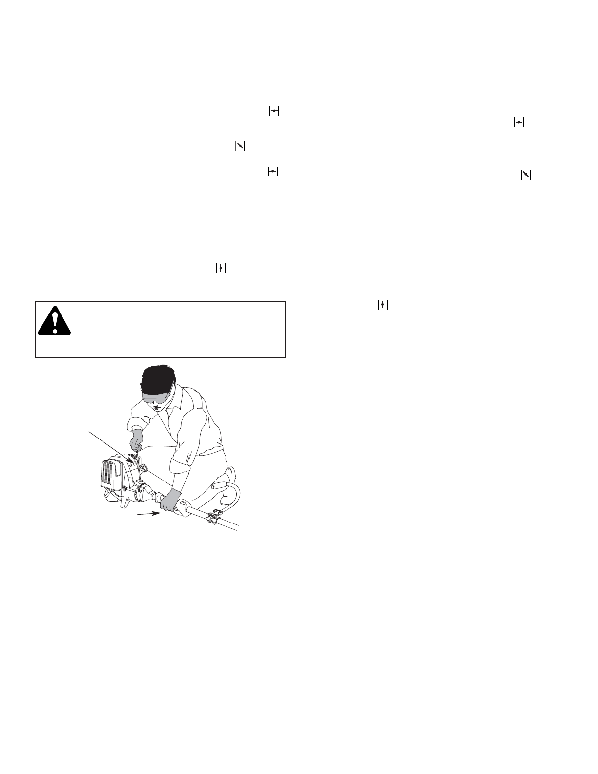
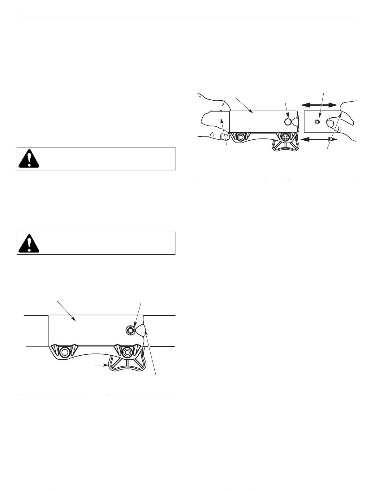
Removing the Cutting Attachment or Add-Ons:
1. Turn the knob counterclockwise to loosen (Fig. 11).
2. Press and hold the release button (Fig. 11).
3. While firmly holding the upper shaft housing, pull
the cutting attachment or add-on straight out of the
EZ-Link™coupler (Fig. 12).
Installing the Cutting Attachment or Add-Ons:
WARNING: To avoid serious personal injury
and damage to the unit, shut unit off before
removing or installing add-ons.
NOTE: To make installing or removing the add-on
easier, place the unit on the ground or on a work
bench.
1. Turn knob counterclockwise to loosen (Fig. 11).
Fig. 11
EZ-Link™ Coupler
Release Button
Guide Recess
Knob
Release
Button Hole
Upper Shaft Housing
EZ-Link™Coupler
2. While firmly holding the add-on, push it straight into
the EZ-Link™coupler (Fig. 12).
NOTE: Aligning the release button with the guide recess
will help installation (Fig. 11).
3. Turn the knob clockwise to tighten (Fig. 11).
Fig. 12
Lower Shaft Housing
Release Button
SECTION 6: OPERATING INSTRUCTIONS
13
Each time the head is bumped, about 1 inch (25.4 mm.)
of trimming line is released. A blade in the cutting
attachment shield will cut the line to the proper length if
excess line is released.
For best results, tap the Bump Head™ on bare ground
or hard soil. If line release is attempted in tall grass, the
engine may stall. Always keep the trimming line fully
extended. Line release becomes more difficult as the
cutting line becomes shorter.
NOTE: Do not rest the Bump Head™ on the ground
while the unit is running .
CAUTION: Do not remove or alter the line
cutting blade assembly. Excessive line length
will make the clutch overheat. This may lead
to serious personal injury or damage to the
unit.
Some line breakage will occur from:
• Entanglement with foreign matter
• Normal line fatigue
• Attempting to cut thick, stalky weeds
• Forcing the line into objects such as walls or fence
posts
TIPS FOR BEST TRIMMING RESULTS
• Keep the cutting attachment parallel to the ground.
• Do not force the cutting attachment. Allow the tip of
the line to do the cutting, especially along walls.
Cutting with more than the tip will reduce cutting
efficiency and may overload the engine.
• Cut grass over 8 inches (200 mm) by working from
top to bottom in small increments to avoid
premature line wear or engine drag.
• Cut from left to right whenever possible. Cutting to
the right improves the unit's cutting efficiency.
Clippings are thrown away from the operator.
• Slowly move the trimmer into and out of the cutting
area at the desired height. Move either in a forwardbackward or side-to-side motion. Cutting shorter
lengths produces the best results.
• Trim only when grass and weeds are dry.
• The life of your cutting line is dependent upon:
• Following the previous trimming techniques
• What vegetation is being cut
•Where it’s being cut
For example, the line will wear faster when trimming
against a foundation wall as opposed to trimming
around a tree.
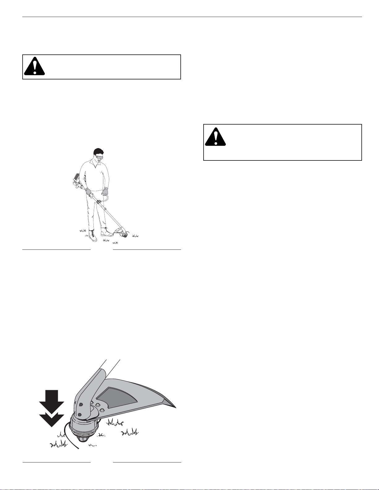
HOLDING THE TRIMMER
WARNING: Always wear eye, hearing, foot
and body protection to reduce the risk of
injury when operating this unit.
Before operating the unit, stand in the operating position
(Fig. 13). Check for the following:
• The operator is wearing eye protection and proper
clothing.
• The right arm is slightly bent, and the hand is holding
the shaft grip.
• The left arm is straight, and the hand is holding the
J-handle.
Fig. 13
• The unit is at waist level.
• The cutting attachment is parallel to the ground and
easily contacts the vegetation to be cut without the
operator having to bend over.
ADJUSTING TRIMMING LINE LENGTH
The Bump Head™ cutting attachment allows you to
release trimming line without stopping the engine. To
release more line, lightly tap the cutting attachment on
the ground (Fig. 14) while operating the trimmer at high
speed.
NOTE: Always keep the trimming line fully extended.
Line release becomes more difficult as cutting
line becomes shorter.
Fig. 14
SECTION 6: OPERATING INSTRUCTIONS
14
WARNING: To prevent serious injury, never
do maintenance or repairs with unit running.
Always do maintenance and repairs on a
cool unit. Disconnect spark plug wire to
ensure the unit will not start.
Fig. 15
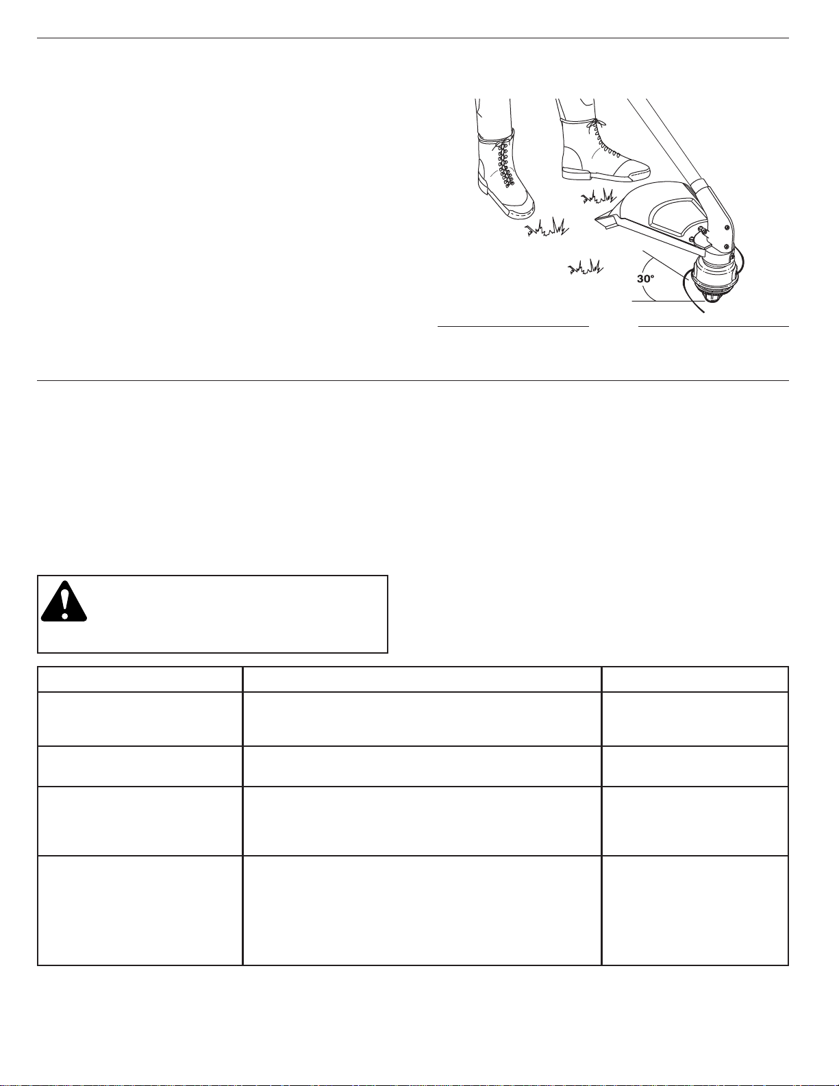
DECORATIVE TRIMMING
Decorative trimming is accomplished by removing all
vegetation around trees, posts, fences, etc.
Rotate the whole unit so that the cutting attachment is at
a 30° angle to the ground (Fig. 15).
NOTE: Some maintenance procedures may require
special tools or skills. If you are unsure about
these procedures take your unit to an authorized
service dealer.
MAINTENANCE SCHEDULE
These required maintenance procedures should be
performed at the frequency stated in the table. They
should also be included as part of any seasonal tune-up.
MAINTENANCE REQUIRED
Fill fuel tank with fresh fuel
Check oil
Clean and re-oil air filter
Change oil
Change oil
Clean spark arrestor
Check rocker arm to valve clearance and adjust as
required
Check rocker arm to valve clearance and adjust as
required
Check spark plug condition and gap
FREQUENCY
Before starting engine
Every 10 hours
1st Change at 10 hours
Every 25 hours there after
Every 25 hours
10 hours on new engine
Every 25 hours
Every 25 hours
REFER TO:
Page 10-11
Page 19
Page 20-21
Page 19-20
Page 19-20
Page 24
Page 22-23
Page 22-23
Page 24
SECTION 6: OPERATING INSTRUCTIONS
SECTION 7: MAINTENANCE AND REPAIR INSTRUCTIONS
15
NOTE: Maintenance, replacement, or repair of the emission
control devices and system may be performed by
any nonroad engine repair establishment, individual
or authorized service dealer.
In order to assure peak performance of your engine,
inspection of the engine exhaust port may be necessary
after 50 hours of operation. If you notice lost RPM, poor
performance or general lack of acceleration, this service
may be required. If you feel your engine is need of this
inspection, refer service to any nonroad engine repair
establishment, individual or authorized service dealer for
repair. DO NOT attempt to perform this process yourself
as engine damage may result from contaminants
involved in the cleaning process for the port.
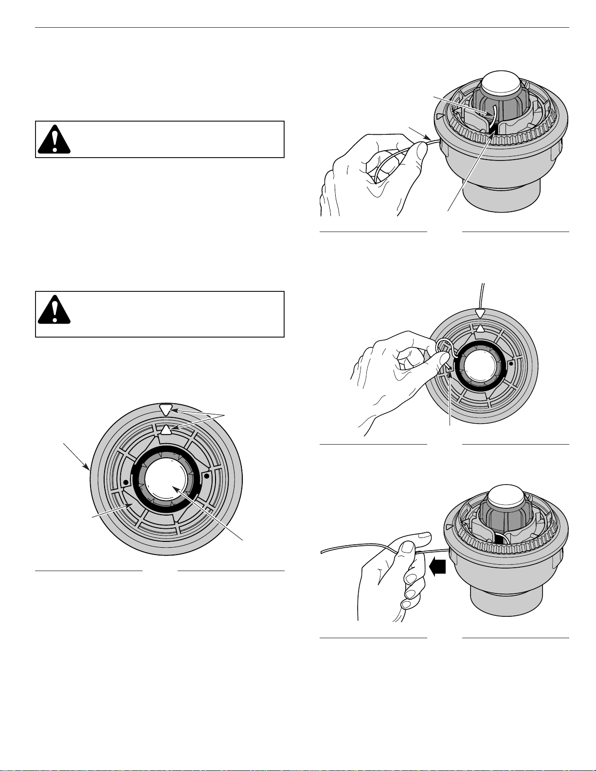
Line Locking Hole
Trimming Line
Line Loading Hole
Eyelet
5. Insert the line into the locking hole (Fig. 18). Do not
push the line more than 1/2 inch (12.7 mm) into the
line locking hole. When inserted correctly the line
will form a small loop (Fig. 18).
6. Pull the line from the outer spool until the line is tight
against the inner reel (Fig. 19).
LINE INSTALLATION FOR THE SPEEDSPOOL
®
Always use genuine MTD 0.080 inch (2.03 mm)
replacement line. Line other than specified may make
the engine overheat or fail.
WARNING: Never use metal-reinforced line,
wire, or rope, etc. These can break off and
become dangerous projectiles.
There are two methods to replace the SpeedSpool
®
trimming line:
• Wind the inner reel with new line
• Install a prewound inner reel
Winding the Inner Reel With New Line
NOTE: It is unnecessary to remove the bump knob to
install new trimming line.
1. Cut two pieces of 0.080 inch (2.03 mm) trimming
line, 10 feet (3 m) long.
WARNING: Always use the correct line
length when installing trimming line on the
unit. The line may not release properly if the
line is too long.
2. Hold the outer spool and turn the inner reel
counterclockwise to line up the arrows on the outer
spool and inner reel (Fig. 16).
3. Pull old line out of the line loading and line locking
holes (Figs. 17 and 18).
4. Insert a piece of trimming line into one of the two
eyelets in the outer spool. Push it up through the line
loading hole in the inner reel (Fig. 17). Do not bend
the line when inserting it into the eyelet.
Top View Of The SpeedSpool
®
Outer Spool
Arrows
Inner Reel
Bump Knob
Fig. 16
Fig. 17
Fig. 19
Fig. 18
16
SECTION 7: MAINTENANCE AND REPAIR INSTRUCTIONS
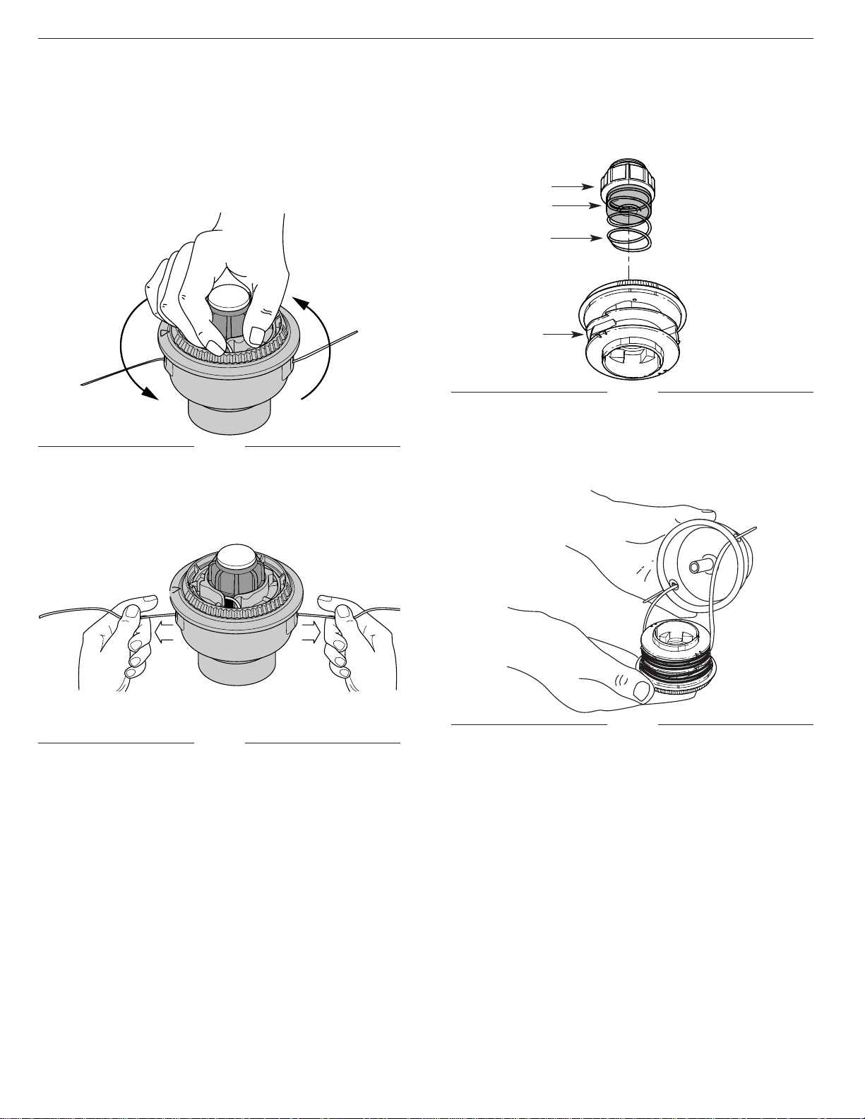
Bump Knob
Foam Seal
Spring
Inner Reel
INSTALLING A PREWOUND REEL
1. Turn the bump knob counterclockwise and remove
the bump knob, spring and foam seal (Fig. 22).
9. If winding the line becomes difficult or the line jams,
pull the ends of the line from the spool (Fig. 21).
Continue winding the inner reel counterclockwise .
4. Hold the inner reel in place and install the bump
knob, spring and foam seal. Press down and turn the
bump knob clockwise. Grasp the ends and pull
firmly to release the line from the holding slots in the
inner reel. (Fig. 21).
Releasing the Inner Reel
If the SpeedSpool
®
does not release line correctly, pull
the ends of the line firmly from the spool (Fig. 21). If this
does not release line, follow the Cleaning the
SpeedSpool®instructions in the Maintenance and
Repair Instructions section.
2. Pull the old inner reel with existing line from the outer
spool.
3. Insert the ends of the prewound inner reel line into
the outer spool eyelets (Fig. 23). Push the new inner
reel, arrow side up, into the outer spool.
7. Repeat procedures 4-6 with the second piece of line.
8. Hold the outer spool. Wind the inner reel
counterclockwise until approximately four (4) inches
(102 mm) of line remain (Fig. 20).
NOTE: Do not wind the inner reel before installing the
second piece of line.
Fig. 20
Fig. 21
Fig. 22
Fig. 23
17
SECTION 7: MAINTENANCE AND REPAIR INSTRUCTIONS
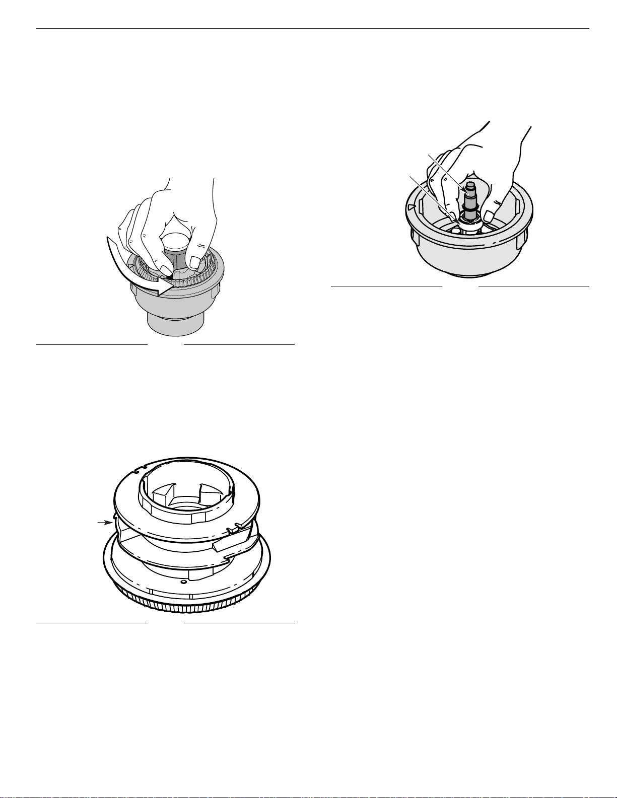
2. Pull out the bump knob, spring and foam seal
(Fig. 22).
3. Pull the inner reel with existing line from the outer
spool (Fig. 23).
4. Remove any existing line from the inner reel before
cleaning. Remove any debris or grass from the knob,
spring, inner reel and foam seal. Wash the inner reel
(Fig. 25) with warm soapy water.
Inner Reel
Shaft
Plunger
NOTE: The inner reel must be totally dry before
reinstalling it into the outer spool. Do not
lubricate the inner reel or outer spool assembly.
6. Place the inner reel into the outer spool.
7. Place the bump knob, spring and foam seal into the
inner reel (Fig. 22).
8. Press the bump knob down and tighten clockwise.
9. Install new line as described in Line Installation for
the SpeedSpool®in the Maintenance and Repair
Instructions section.
5. Clean the shaft and the inner surface of the outer
spool. To clean the shaft underneath the plunger,
press down on the plunger (Fig. 26). Remove any dirt
or debris from the shaft.
Fig. 24
Fig. 26
Fig. 25
CLEANING THE SPEEDSPOOL
®
Cleaning the SpeedSpool®may be necessary:
• To remove jammed or excess line, or
• If the SpeedSpool®becomes difficult to wind or
does not operate correctly when bumping the head
on the ground.
1. Hold the outer spool, and unscrew the bump knob
counterclockwise (Fig. 24).
SPEEDSPOOL
®
REPLACEMENT PARTS
Replacement Line . . . . . . . . . . . . . . . . . . . . 791-181472
Replacement Line Cartridge . . . . . . . . . . . 791-181460B
Inner Reel Spring . . . . . . . . . . . . . . . . . . . . 791-181465B
Foam Seal . . . . . . . . . . . . . . . . . . . . . . . . . . 791-181467
Inner Reel . . . . . . . . . . . . . . . . . . . . . . . . . 791-181460B
Bump Head™ Knob Assembly . . . . . . . . . 791-181468B
(Bump Head™, Inner Reel, Spring, )
These SpeedSpool®replacement parts can be
purchased from your local authorized dealer.
18
SECTION 7: MAINTENANCE AND REPAIR INSTRUCTIONS
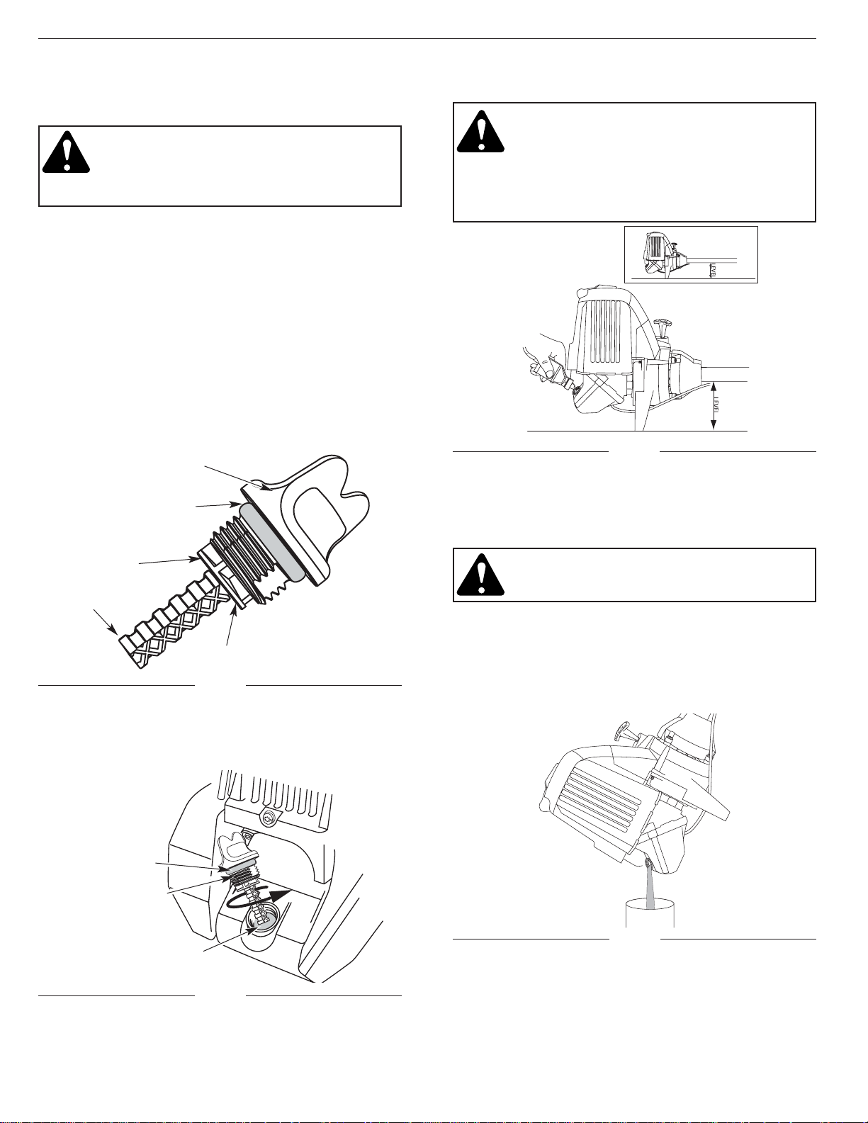
CHECKING THE OIL LEVEL
CAUTION: To prevent extensive engine wear
and damage to the unit, always maintain the
proper oil level in the crankcase. Never
operate the unit with the oil level below the
bottom of the dipstick.
The importance of checking and maintaining the proper
oil level in the crankcase cannot be overemphasized.
Check oil before each use:
1. Stop engine and allow oil to drain into the crankcase.
2. Place the unit on a flat, level surface to get a proper
oil level reading.
3. Keep dirt, grass clippings, etc., out of the engine.
Clean the area around the oil fill plug/dipstick before
removing it.
4. Remove the oil fill plug/dipstick and wipe off oil.
Reinsert it all the way back in.
5. Remove the oil fill plug/dipstick and check oil level.
Oil should be up to the top of the dipstick (Fig. 27).
6. If the level is low, add a small amount of oil to the oil
fill hole and recheck (Fig. 27). Repeat until the oil
level reaches the top of the dipstick.
NOTE: Do not overfill the unit.
Top of Dipstick
O-Ring
Oil Fill Plug/Dipstick
CHANGING THE OIL
For a new engine, change the oil after the first 10 hours
of operation. Change the oil while the engine is still
warm. The oil will flow freely and carry away more
impurities.
CAUTION: Wear gloves to prevent injury
when handling the unit.
1. Unplug spark plug wire to eliminate starting.
2. Remove the oil fill plug/dipstick.
3. Pour the oil out of the oil fill hole and into a container
by tipping the unit to a vertical position (Fig. 30).
Allow ample time for complete drainage.
Fig. 30
Fig. 27
Fig. 28
NOTE: Make sure the O-ring is in place on the oil fill
plug/dipstick when checking and changing the
oil (Fig. 28).
Oil Fill Plug/Dipstick
Oil Fill Hole
O-Ring
Full
Add 1.4-1.5 Oz.
(41-44 ml)
19
SECTION 7: MAINTENANCE AND REPAIR INSTRUCTIONS
Fig. 29
DANGER: OVERFILLING OIL CRANKCASE
MAY CAUSE SERIOUS PERSONAL INJURY!
The importance of checking and maintaining
the proper oil level in the crank case cannot
be overemphasized. Check oil before each
use and change as needed. See Changing
the Oil below.
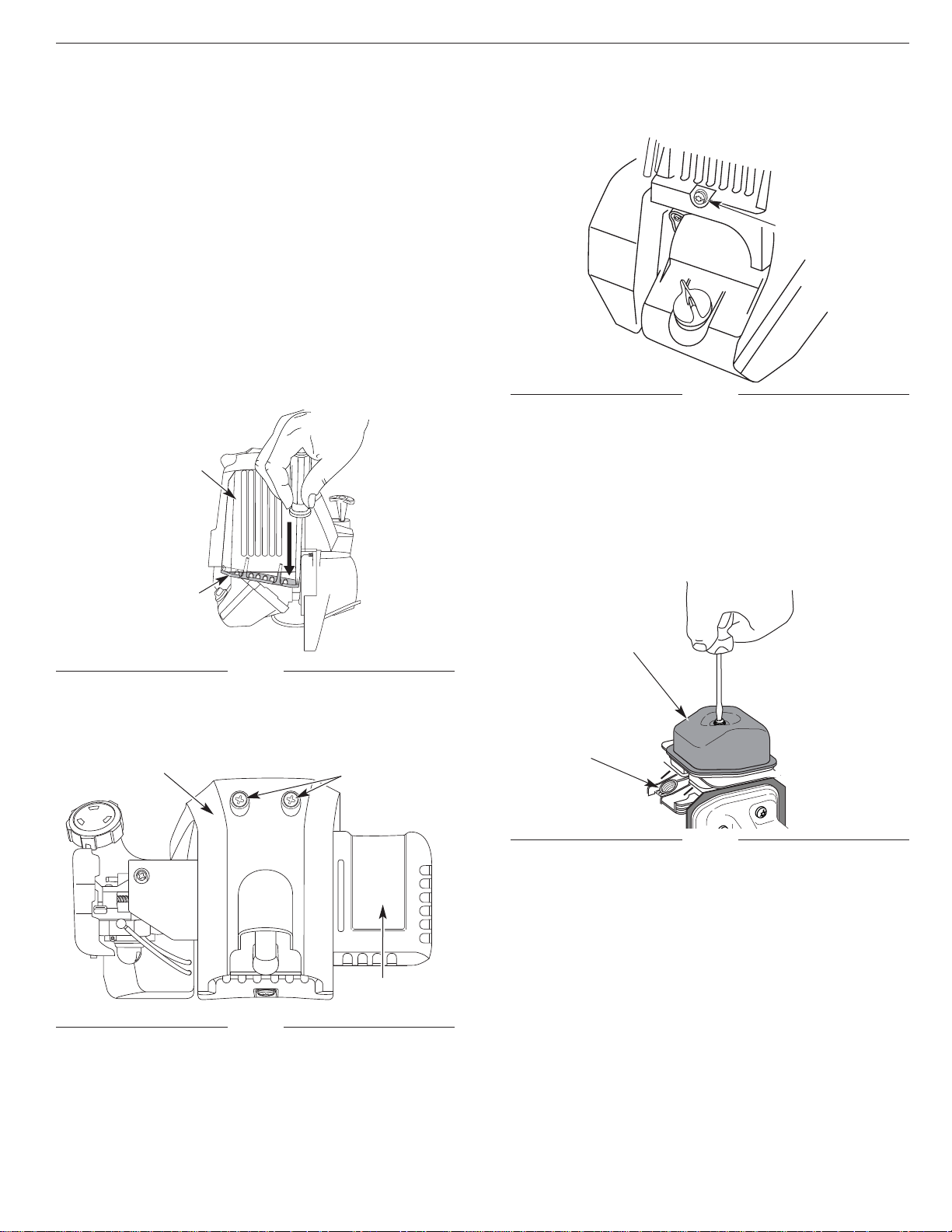
AIR FILTER MAINTENANCE
Cleaning the Air Filter
WARNING: To avoid serious personal injury,
always turn your trimmer off and allow it to
cool before you clean it or do any
maintenance on it.
Clean and re-oil the air filter every 10 hours of operation.
It is an important item to maintain. Not maintaining the
air filter will VOID the warranty.
1. Open the air filter cover. Push the tab on the right
side of the cover in, pull the air filter cover out and to
the left (Fig. 32).
NOTE: It may be necessary to remove the fuel cap to
completely remove the air filter cover
2. Remove the air filter (Fig. 32).
3. Wash the filter in detergent and water (Fig. 33). Rinse
the filter thoroughly and allow it to dry.
4. Apply enough clean SAE 30 motor oil to lightly coat
the filter (Fig. 34).
Air Filter
Choke Lever
Air Filter Cover
Tab
Fig. 32
Fig. 33
Fig. 34
20
SECTION 7: MAINTENANCE AND REPAIR INSTRUCTIONS
6. Replace the oil fill plug/dipstick.
7. Reconnect spark plug wire.
Fig. 31
4. Wipe up any oil residue on the unit and clean up any
oil that may have spilled. Dispose of the oil
according to Federal, State and Local regulations.
5. Refill the crankcase with 3.4 fluid ounce (100 ml) of
SAE 30 SF, SG, SH oil.
NOTE: Use the bottle and spout saved from initial use to
measure the correct amount. 3.4 ounce (100 ml)
is approximately to the top of the label on the
bottle (Fig. 31). Check the level with the dipstick.
If the level is low, add a small amount of oil and
recheck (Fig. 27). Do not overfill.
Fill Level
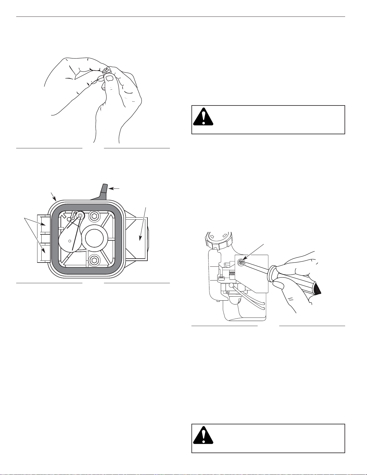
CARBURETOR ADJUSTMENT
The idle speed of the engine is adjustable. An idle
adjustment screw is reached though a hole in the top of
the engine cover (Fig 37).
NOTE: Careless adjustments can seriously damage your
unit. An authorized service dealer should make
carburetor adjustments.
Check Fuel
Old fuel is usually the main reason for the unit not
running properly. Drain and refill the tank with clean,
fresh unleaded fuel prior to doing any adjustments. Refer
to the Oil and Fuel Information section.
3. If the cutting attachment rotates when the engine
idles, turn the idle speed screw counterclockwise 1/8
of a turn at a time (as needed), to reduce idle speed.
Checking the fuel, cleaning the air filter, and adjusting
the idle speed screw should solve most engine
problems.
If not and:
• The engine will not idle,
• The engine hesitates or stalls on acceleration,
• There is a loss of engine power,
have the carburetor adjusted by an authorized service
dealer.
WARNING: When the unit is turned off make
sure the cutting attachment has stopped
before the unit is set down to prevent serious
personal injury.
Idle Adjustment Screw
Fig. 37
21
SECTION 7: MAINTENANCE AND REPAIR INSTRUCTIONS
Clean Air Filter
The condition of the air filter is important to the operation
of the unit. A dirty air filter will restrict air flow and
change the air/fuel mixture. This is often mistaken for an
out of adjustment carburetor. Check the condition of the
air filter before adjusting the idle speed screw. Refer to
Air Filter Maintenance in the Maintenance and Repair
Instructions section.
Adjust Idle Speed Screw
WARNING: The cutting attachment may be
spinning during idle speed adjustment. Wear
protective clothing and observe all safety
instructions to prevent serious personal injury.
If after checking the fuel and cleaning the air
filter the engine still will not idle, adjust the idle speed
screw as follows.
1. Start the engine and let it run at a high idle for a
minute to warm up.
2. Release the throttle trigger and let the engine idle. If
the engine stops, insert a small phillips or flat blade
screwdriver into the hole in the engine cover
(Fig. 37). Turn the idle speed screw in, clockwise,
1/8 of a turn at a time (as needed) until the engine
idles smoothly.
NOTE: The cutting attachment should not rotate when
the engine idles.
Fig. 36
Back Plate Slot
Slots
Choke Lever
7. Reinstall the air filter cover. Position the hooks on
the left side of the air filter cover into the slots at the
left side of the back plate (Fig. 36).
NOTE: It may be necessary to remove the fuel cap to
reinstall the air filter cover
8. Swing the cover to the right until the tab on the air
filter cover snaps into place in the slot on the back
plate (Fig. 36).
9. Replace the fuel cap, if removed.
Back Plate
Fig. 35
5. Squeeze the filter to spread and remove excess oil
(Fig. 36).
6. Replace the filter (Fig. 35).
NOTE: If the unit is operated without the air filter, you
will VOID the warranty.
4. Disconnect the spark plug wire.
5. Clean dirt from around the spark plug. Remove the
spark plug from the cylinder head by turning a 5/8 in.
socket counterclockwise.
6. Remove the engine cover (Fig. 39).
7. Clean dirt from around the rocker arm cover.
Remove the screw holding the rocker arm cover with
a large flat blade screwdriver or Torx T25 bit
(Fig. 41). Remove the rocker arm cover and gasket.
3. Remove the screw behind the engine cover (Fig. 40).
Remove Screws
Rocker Arm Cover
Screw
Fig. 38
Fig. 40
Fig. 41
Engine Cover
Spark Plug Hole
2. Remove the two (2) screws on top of the engine
cover with an appropriate screwdriver (Fig. 39).
Fig. 39
Muffler Cover
Engine Cover
Muffler
ROCKER ARM CLEARANCE
This requires disassembly of the engine. If you feel
unsure or unqualified to perform this, take the unit to an
authorized service center.
NOTE: Inspect the valve to rocker arm clearance with a
feeler gauge after the first 10 hours of operation
and then every 25 hours of operation thereafter.
• The engine must be cold when checking or adjusting
the valve clearance.
• This task should be performed inside, in a clean, dust
free area.
1. Remove the muffler cover by pressing down on the
corner with a flat blade screwdriver (Fig. 38). Slide
the notches on the sides of the muffler cover over
the tabs on the engine cover and remove
8. Pull the starter rope slowly to bring the piston to the
top of its travel, (known as top dead center). Check
that:
• The piston is at the top of its travel while looking in
the spark plug hole (Fig. 41).
• Both rocker arms move freely, and both valves are
closed.
If not, repeat this step.
Top View Of The Engine
22
SECTION 7: MAINTENANCE AND REPAIR INSTRUCTIONS
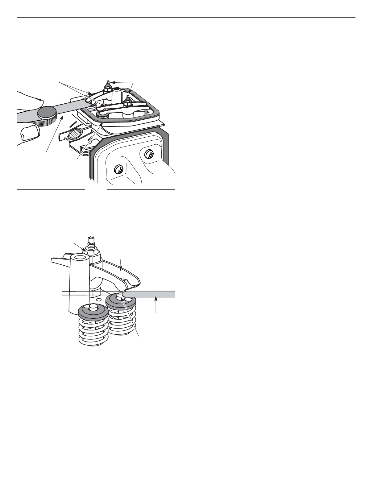
10. If the clearance is not within specification:
a. Turn the adjusting nut using a 5/16 inch (8 mm)
wrench or nut driver (Fig. 42).
• To increase clearance, turn the adjusting nut
counterclockwise.
• To decrease clearance, turn the adjusting nut
clockwise.
b. Recheck both clearances, and adjust as necessary.
11. Reinstall the rocker arm cover using a new gasket.
Torque the screw to 20–30 in•
lb (2.2–3.4 N•m).
NOTE: A rocker arm cover gasket, Part # 791-182099
can be purchased from your local authorized
dealer.
12. Reinstall the engine cover. Check alignment of the
cover before tightening the screws. Tighten screws.
13. Replace the muffler cover. Slip the long tabs on the
muffler cover into the engine cover. Slide the
notches on the side of the muffler cover over the
tabs on the engine cover and snap into place
(Fig. 38).
14. Check the spark plug and reinstall. See Replacing
the Spark Plug in the Maintenance and Repair
Instructions section.
15. Replace the spark plug wire.
9. Slide the feeler gauge between the rocker arm and
the valve return spring. Measure the clearance
between the valve stem and rocker arm (Fig 42).
Do both intake and exhaust valves.
Adjusting Nuts
Feeler Gauge
Rocker Arms
Gasket
Fig. 42
Fig. 43
The recommended clearance for both intake and
exhaust is .003 – .006 in. (.076 – 0.152 mm). Use a
standard automotive .005 in. (0.127 mm) feeler gauge.
The feeler gauge should slide between the rocker arm
and valve stem with a slight amount of resistance,
without binding (Fig. 43).
Feeler Gauge
Adjusting Nut
Rocker Arm
.003–.006 in.
(.076–0.152 mm)
Valve Stem
23
SECTION 7: MAINTENANCE AND REPAIR INSTRUCTIONS
ACCESSORIES/REPLACEMENT PARTS
4-Cycle Oil . . . . . . . . . . . . . . . . . . . . . . . . . . 791-181786
Oil Fill Plug / Dipstick . . . . . . . . . . . . . . . . . . 791-182378
Spark Plug . . . . . . . . . . . . . . . . . . . . . . . . . 791-180852B
Spark Arrestor Screen . . . . . . . . . . . . . . . . . 791-180890
Replacement Line Cartridge . . . . . . . . . . .791-181460B
Inner Reel Spring . . . . . . . . . . . . . . . . . . . . 791-181465B
Bump Head™ Knob Assembly . . . . . . . . . 791-181468B
Fuel Cap . . . . . . . . . . . . . . . . . . . . . . . . . . . 791-181083
Shoulder Harness . . . . . . . . . . . . . . . . . . .791- 682075B
Coupler . . . . . . . . . . . . . . . . . . . . . . . . . . . 791-181616B
0.025 in.
(0.655 mm.)
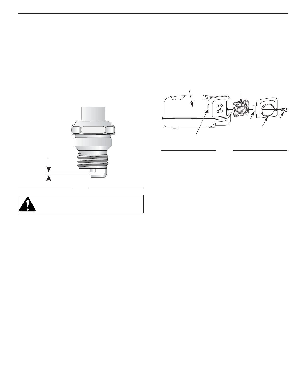
REPLACING THE SPARK PLUG
Use only genuine MTD spark plugs. The correct air gap
is 0.025 in. (0.655 mm.). Remove the plug after every 50
hours of operation and check its condition.
1. Stop the engine and allow it to cool. Grasp the plug
wire firmly and pull the cap from the spark plug.
2. Clean dirt from around the spark plug. Remove the
spark plug from the cylinder head by turning a 5/8 in.
socket counterclockwise.
3. Replace cracked, fouled or dirty spark plug. Set the
air gap at 0.025 in. (0.655 mm.) using a feeler gauge
(Fig. 44).
Fig. 44
CAUTION: Do not sand blast, scrape, or clean
electrodes. Grit in the engine could damage the
cylinder.
4. Install a correctly gapped spark plug in the cylinder
head. Tighten by turning the 5/8 in. socket clockwise
until snug.
If using a torque wrench torque to;
110-120 in.•lb. (12.3-13.5 N•m).
Do not over tighten.
5. Replace the spark plug wire.
NOTE: A replacement spark plug Part # 791-180852 can
be purchased from your local authorized dealer.
Fig. 45
Muffler
Spark Arrestor Screen
Spark Arrestor Cover
Screw
Tab
Slot
SPARK ARRESTOR MAINTENANCE
1. Remove the muffler cover. See Rocker Arm
Clearance in the Maintenance and Repair
Instructions section.
2. With a flat blade screwdriver or Torx T20 bit, remove
the screw attaching the spark arrestor cover to the
muffler (Fig. 45).
3. Pull the tab on the spark arrestor cover out of the
muffler. Remove the spark arrestor cover.
4. Remove the spark arrestor screen from the spark
arrestor cover.
5. Clean the spark arrestor screen with a wire brush, or
replace.
6. Reinstall the spark arrestor screen, spark arrestor
cover, and screw.
NOTE: A replacement spark arrestor screen Part # 791-
180890 can be purchased from your local
authorized dealer.
24
SECTION 7: MAINTENANCE AND REPAIR INSTRUCTIONS

LONG TERM STORAGE
If the unit will be stored for an extended time,
1. Drain all gasoline from the gas tank into a container .
Do not use gas that has been stored for more than
60 days. Dispose of the old gasoline in accordance
to Federal, State, and Local regulations.
2. Start the engine and allow it to run until it stalls. This
ensures that all gasoline has been drained from the
carburetor.
3. Allow the engine to cool. Remove the spark plug and
put 1 oz. (30 ml) of high quality motor oil into the
cylinder. Pull the starter rope slowly to distribute the
oil. Reinstall the spark plug.
NOTE: Remove the spark plug and drain all of the oil
from the cylinder before attempting to start the
trimmer after storage.
4. Change the oil. See Changing the Oil in the
Maintenance and Repair Instructions section.
Dispose of the old oil in accordance to Federal,
State, and Local regulations.
5. Thoroughly clean the unit and inspect for any loose
or damaged parts. Repair or replace damaged parts
and tighten loose screws, nuts or bolts. The unit is
ready for storage.
TRANSPORTING
• Allow the engine to cool before transporting.
• Secure the unit while transporting.
• Drain the gas tank before transporting.
• Tighten gas cap before transporting.
CLEANING
WARNING: To avoid serious personal injury,
always turn your trimmer off and allow it to
cool before you clean or do any maintenance
on it.
Use a small brush to clean off the outside of the unit. Do
not use strong detergents. Household cleaners that
contain aromatic oils such as pine and lemon, and such
as kerosene, can damage plastic housing or handle.
Wipe off any moisture with a soft cloth.
STORAGE
• Never store the unit with gasoline in the tank where
fumes may reach an open flame or spark.
• Allow the engine to cool before storing.
• Store the unit locked up to prevent unauthorized use
or damage.
• Store the unit in a dry, well ventilated area.
• Store the unit out of the reach of children.
Store the unit in one of three (3) positions:
1. The unit hanging by the cutting attachment end.
2. The unit hanging by the engine.
3. The unit setting upright on the cutting attachment
shield and engine feet.
25
SECTION 8: CLEANING AND STORAGE

CAUSE ACTION
Oil in cutting head Clean the cutting attachment
If further assistance is required, contact your authorized service dealer.
CAUSE ACTION
Cutting head bound with grass Stop the engine and clean cutting attachment
Cutting head out of line Refill with new line
Inner reel bound up Replace the inner reel
Cutting head dirty Clean inner reel and outer spool
Line welded Disassemble, remove the welded section
and rewind the line
Line twisted when refilled Disassemble and rewind the line
Not enough line is exposed Push the bump knob and pull out line until
4 inches (102 mm) of line is outside of the
cutting attachment
CAUSE ACTION
Old gasoline Drain fuel tank / Add fresh gasoline
Improper carburetor adjustment Take to an authorized service dealer for
carburetor adjustment
Clogged spark arrestor screen Clean or replace
CAUSE ACTION
Ignition switch is OFF Turn switch to ON
Empty fuel tank Fill fuel tank
Primer bulb wasn't pressed enough Press primer bulb fully and slowly 5-7 times
Engine flooded Use starting procedure with choke lever in the
RUN position
Old gasoline Drain fuel tank / Add fresh gasoline
Fouled spark plug Replace or clean the spark plug
ENGINE WILL NOT START
ENGINE WILL NOT IDLE
ENGINE WILL NOT ACCELERATE
ENGINE LACKS POWER OR STALLS WHEN CUTTING
CAUSE ACTION
Air filter is plugged Replace or clean the air filter
Old gasoline Drain fuel tank / Add fresh gasoline
Improper carburetor adjustment Adjust per instruction
CAUSE ACTION
Old gasoline Drain gas tank / Add fresh gasoline
Improper carburetor adjustment Take to an authorized service dealer for
carburetor adjustment
Cutting head bound with grass Stop the engine and clean the cutting attachment
Dirty air filter Clean or replace the air filter
Clogged spark arrestor screen Clean or replace
CUTTING HEAD WILL NOT ADVANCE LINE
CUTTING LINE ADVANCES UNCONTROLLABLY
26
SECTION 9: TROUBLESHOOTING

ENGINE
Engine Type . . . . . . . . . . . . . . . . . . . . . . . . . . . . . . . . . . . . . . . . . . . . . . . . . . . . . . . . . . . . . . . . . Air-Cooled, 4-Cycle
Displacement . . . . . . . . . . . . . . . . . . . . . . . . . . . . . . . . . . . . . . . . . . . . . . . . . . . . . . . . . . . . . . . . . 1.6 cu. in. (26.2 cc)
Clutch Type . . . . . . . . . . . . . . . . . . . . . . . . . . . . . . . . . . . . . . . . . . . . . . . . . . . . . . . . . . . . . . . . . . . . . . . . . Centrifugal
Operating RPM . . . . . . . . . . . . . . . . . . . . . . . . . . . . . . . . . . . . . . . . . . . . . . . . . . . . . . . . . . . . . . . . . . 7200-8300 rpm
Idle Speed RPM . . . . . . . . . . . . . . . . . . . . . . . . . . . . . . . . . . . . . . . . . . . . . . . . . . . . . . . . . . . . . . . . . . 3000-4500 rpm
Operating Switch Type . . . . . . . . . . . . . . . . . . . . . . . . . . . . . . . . . . . . . . . . . . . . . . . . . . . . . Electronic Rocker Switch
Valve clearance (intake and exhaust) . . . . . . . . . . . . . . . . . . . . . . . . . . . . . . . . . . . . . .003–.006 in. (.076–.0152 mm)
Spark Plug Gap . . . . . . . . . . . . . . . . . . . . . . . . . . . . . . . . . . . . . . . . . . . . . . . . . . . . . . . . . . . . 0.025 inch (0.655 mm)
Lubrication . . . . . . . . . . . . . . . . . . . . . . . . . . . . . . . . . . . . . . . . . . . . . . . . . . . . . . . . . . . . . . . . . . . . . . . . . . SAE 30 Oil
Crankcase Oil Capacity . . . . . . . . . . . . . . . . . . . . . . . . . . . . . . . . . . . . . . . . . . . . . . . . . . . . . . . . . . . . 3.4 oz (100 ml)
Fuel . . . . . . . . . . . . . . . . . . . . . . . . . . . . . . . . . . . . . . . . . . . . . . . . . . . . . . . . . . . . . . . . . . . . . . . . . . . . . . . . Unleaded
Carburetor . . . . . . . . . . . . . . . . . . . . . . . . . . . . . . . . . . . . . . . . . . . . . . . . . . . . . . . . . . . . . . . . Diaphragm, All-Position
Starter . . . . . . . . . . . . . . . . . . . . . . . . . . . . . . . . . . . . . . . . . . . . . . . . . . . . . . . . . . . . . . . . . . . . . . . . . . . . Auto Rewind
Muffler . . . . . . . . . . . . . . . . . . . . . . . . . . . . . . . . . . . . . . . . . . . . . . . . . . . . . . . . . . . . . . . . . . . . . . . Baffled with Guard
Throttle . . . . . . . . . . . . . . . . . . . . . . . . . . . . . . . . . . . . . . . . . . . . . . . . . . . . . . . . . . . . . . . . . . . . Manual Spring Return
Fuel Tank Capacity . . . . . . . . . . . . . . . . . . . . . . . . . . . . . . . . . . . . . . . . . . . . . . . . . . . . . . . . . . . . . . . . . 12 oz (355 ml)
Fuel Tank . . . . . . . . . . . . . . . . . . . . . . . . . . . . . . . . . . . . . . . . . . . . . . . . . . . . . . . . . . . . . . . . . . . . . . . HD Polyethylene
ENGINE
DRIVE SHAFT & CUTTING ATTACHMENT
Drive Shaft Housing . . . . . . . . . . . . . . . . . . . . . . . . . . . . . . . . . . . . . . . . . . . . . . . . . . . . . . . Aluminum Tube (EZ-Link)
Throttle Control . . . . . . . . . . . . . . . . . . . . . . . . . . . . . . . . . . . . . . . . . . . . . . . . . . . . . . . . . . . . . . . . . Finger-Tip Trigger
Unit Weight (No Fuel, with J-handle, Cutting attachment shield and Cutting attachment) . . . . . . . 13.5 lbs (6.13 kg)
Cutting Mechanism . . . . . . . . . . . . . . . . . . . . . . . . . . . . . . . . . . . . . . . . . . . . . . . . . . . . . . . . Dual String Cutting Head
Line Spool . . . . . . . . . . . . . . . . . . . . . . . . . . . . . . . . . . . . . . . . . . . . . . . . . . . . . . . . . . . . . . . . . . . Bump Line Releaser
Line Spool Diameter . . . . . . . . . . . . . . . . . . . . . . . . . . . . . . . . . . . . . . . . . . . . . . . . . . . . . . . . . . . 3 inches (76.2 mm)
Trimming Line Diameter . . . . . . . . . . . . . . . . . . . . . . . . . . . . . . . . . . . . . . . . . . . . . . . . . . . . . 0.080 inches (2.03 mm)
Cutting Path Diameter . . . . . . . . . . . . . . . . . . . . . . . . . . . . . . . . . . . . . . . . . . . . . . . . . . . . . . . . . . 16 inches (40.6 cm)
27
SECTION 10: SPECIFICATIONS
28
Reissued 5/02
1
49
48A
48B
52
53
54
55
57
56
50
51
58
60
61
64
93
62
63
73
78
79
80
77
76
75
71
69
81
82
83
85
84
74
70
72
86
87
88
89
87
90
70
68
92
67
66
65
94
59
2
3
18
19
20
21
22
23
24
25
26
27
91
28
29
30
32
33
35
38
4
5
8
12
6
7
9
10
11
15
13
40
14
17
16
41
39
45
42
43
44
46
47
31
34
37
36
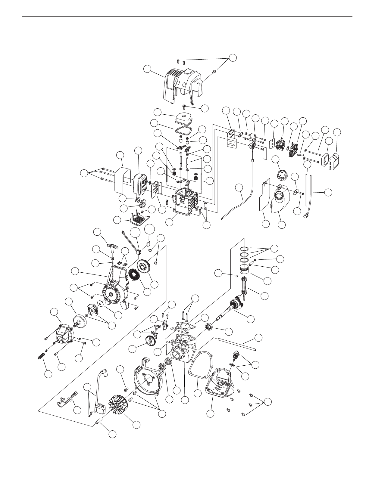
SECTION 11: PARTS LIST FOR PPN 41AD26SC401
 Loading...