


Safety • Set-Up • Operation • Adjustments • Maintenance • Troubleshooting • Parts Lists • Warranty
OPERATOR’S MANUAL
Two-Stage Snow Thrower
IMPORTANT:
READ SAFETY RULES AND
INSTRUCTIONS CAREFULLY
BEFORE OPERATION
PRINTED IN U.S.A.
MTD Products Ltd., P. O. Box 1386, KITCHENER, ONTARIO N2G 4J1
769-03245
06/05/07

This Operator’s Manual is an important part of your new snow thrower. It will help you assemble,
-4$02/$5#43,)-)4%$
+)4#(%.%2/..'*
8888888888
88888888888
-ODEL.UMBER
.UM£RODEMODÞLE
3ERIAL.UMBER
.UM£RODES£RIE
WWWMTDCANADACOM
prepare and maintain the unit for best performance. Please read and understand what it says.
Table of Contents
Safety Labels ......................................................3
Safe Operation Practices ................................... 4
Setting Up Your Snow Thrower .......................... 6
Operating Your Snow Thrower ......................... 10
Making Adjustments ........................................14
Finding and Recording Model Number
BEFORE YOU START ASSEMBLING
YOUR NEW EQUIPMENT,
please locate the model plate on the equipment and copy the
model number and the serial number to the sample model
plate provided to the right. You can locate the model plate by
standing at the operating position and looking down at the
frame.
Maintaining Your Snow Thrower ...................... 16
Off-Season Storage .......................................... 20
Trouble Shooting .............................................. 21
Warranty ............................................................ 22
Illustrated Parts Lists ....................................... 23
Customer Support
Please do
If you have difficulty assembling this product or have any questions regarding the controls, operation or maintenance of this unit,
you can seek help from the experts. Choose from the options below:
1. Visit www.yardman.ca for many useful suggestions, click on Customer Support button.
2. Call a Customer Support Representative at 1-800-668-1238
3. The engine manufacturer is responsible for all engine-related issues with regards to performance, power-rating, specifications, warranty and service. Please refer to the engine manufacturer’s Owner’s/Operator’s Manual, packed separately with
your unit, for more information.
Please have your unit’s model number and serial number ready when you call. See previous section to locate this information.
You will be asked to enter the serial number in order to process your call.
NOT
return the unit to the retailer from which it was purchased,
without first contacting Customer Support.
2

#3
Chute Clean-out
Tool
A chute clean-out tool is fastened to the top
of the auger housing with a mounting clip. The
tool is designed to clear a chute assembly of
ice and snow.
This item is fastened with a cable tie at the
factory. Cut the cable tie before operating the
snow thrower.
WARNING: Never use your
hands to clear a clogged chute
assembly. Shut off engine and
remain behind handles until
all moving parts have stopped
before using the clean-out tool
to clear the chute assembly.
1
Safety
Labels
WARNING
This symbol points
out important safety
instructions which,
if not followed, could
endanger the personal safety and/or
property of yourself
and others. Read and
follow all instructions
in this manual before
attempting to operate
this machine. Failure
to comply with these
instructions may
result in personal
injury. When you see
this symbol, HEED
ITS WARNING!
Your Responsibility
Restrict the use
of this power machine
to persons who read,
understand
and follow the warnings
and instructions
in this manual
and on the machine.
3

WARNING: Engine Exhaust, some of its constituents, and certain vehicle components contain or emit chemicals known to State of California to cause cancer and
birth defects or other reproductive harm.
2
Safe
Operation
Practices
WARNING
This symbol points
out important safety
instructions which,
if not followed, could
endanger the personal safety and/or
property of yourself
and others. Read and
follow all instructions
in this manual before
attempting to operate
this machine. Failure
to comply with these
instructions may
result in personal
injury. When you see
this symbol, HEED
ITS WARNING!
Your Responsibility
Restrict the use
of this power machine
to persons who read,
understand
and follow the warnings
and instructions
in this manual
and on the machine.
DANGER: This machine was built to be operated according to the safe operation practices in this
manual. As with any type of power equipment, carelessness or error on the part of the operator can
result in serious injury. This machine is capable of amputating hands and feet and throwing objects.
Failure to observe the following safety instructions could result in serious injury or death.
Training
1. Read, understand, and follow all instructions on the
machine and in the manual(s) before attempting to
assemble and operate. Keep this manual in a safe place for
future and regular reference and for ordering replacement
parts.
2. Be familiar with all controls and their proper operation.
Know how to stop the machine and disengage them quickly.
3. Never allow children under 14 years old to operate this
machine. Children 14 years old and over should read and
understand the instructions and safe operation practices
in this manual and on the machine and be trained and
supervised by an adult.
4. Never allow adults to operate this machine without proper
instruction.
5. Thrown objects can cause serious personal injury. Plan
your snow-throwing pattern to avoid discharge of material
toward roads, bystanders and the like.
6. Keep bystanders, helpers, pets and children at least 75 feet
from the machine while it is in operation. Stop machine if
anyone enters the area.
7. Exercise caution to avoid slipping or falling, especially
when operating in reverse.
Preparation
1. Thoroughly inspect the area where the equipment is to be
used. Remove all doormats, newspapers, sleds, boards,
wires and other foreign objects, which could be tripped
over or thrown by the auger/impeller.
2. Always wear safety glasses or eye shields during
operation and while performing an adjustment or repair
to protect your eyes. Thrown objects which ricochet can
cause serious injury to the eyes.
3. Do not operate without wearing adequate winter outer gar
ments. Do not wear jewelry, long scarves or other loose
clothing, which could become entangled in moving parts.
Wear footwear which will improve footing on slippery
surfaces.
4. Use a grounded three-wire extension cord and receptacle
for all units with electric start engines.
5. Adjust collector housing height to clear gravel or crushed
rock surfaces.
6. Disengage all control levers before starting the engine.
7. Never attempt to make any adjustments while engine is
running, except where specifically recommended in the
operator’s manual.
8. Let engine and machine adjust to outdoor temperature
before starting to clear snow.
Safe Handling of Gasoline
To avoid personal injury or property damage use extreme care
in handling gasoline. Gasoline is extremely flammable and the
vapors are explosive. Serious personal injury can occur when
gasoline is spilled on yourself or your clothes, which can ignite.
Wash your skin and change clothes immediately.
a. Use only an approved gasoline container.
b. Extinguish all cigarettes, cigars, pipes and other sources
of ignition.
c. Never fuel machine indoors.
d. Never remove gas cap or add fuel while the engine is hot
or running.
e. Allow engine to cool at least two minutes before refuel
ing.
f. Never over fill fuel tank. Fill tank to no more than ½ inch
below bottom of filler neck to provide space for fuel
expansion.
g. Replace gasoline cap and tighten securely.
h. If gasoline is spilled, wipe it off the engine and equip
ment. Move machine to another area. Wait 5 minutes
before starting the engine.
i. Never store the machine or fuel container inside where
there is an open flame, spark or pilot light (e.g. furnace,
water heater, space heater, clothes dryer etc.).
j. Allow machine to cool at least 5 minutes before storing.
-
-
-
4

Operation
1. Do not put hands or feet near rotating parts, in the
auger/impeller housing or chute assembly. Contact with the
rotating parts can amputate hands and feet.
2. The auger/impeller control lever is a safety device. Never
bypass its operation. Doing so makes the machine unsafe
and may cause personal injury.
3. The control levers must operate easily in both directions
and automatically return to the disengaged position when
released.
4. Never operate with a missing or damaged chute assembly.
Keep all safety devices in place and working.
5. Never run an engine indoors or in a poorly ventilated area.
Engine exhaust contains carbon monoxide, an odorless and
deadly gas.
6. Do not operate machine while under the influence of alcohol
or drugs.
7. Muffler and engine become hot and can cause a burn. Do
not touch.
8. Exercise extreme caution when operating on or crossing
gravel surfaces. Stay alert for hidden hazards or traffic.
9. Exercise caution when changing direction and while operat
ing on slopes.
10. Plan your snow-throwing pattern to avoid discharge towards
windows, walls, cars etc. Thus, avoiding possible property
damage or personal injury caused by a ricochet.
11. Never direct discharge at children, bystanders and pets or
allow anyone in front of the machine.
12. Do not overload machine capacity by attempting to clear
snow at too fast of a rate.
13. Never operate this machine without good visibility or light.
Always be sure of your footing and keep a firm hold on the
handles. Walk, never run.
14. Disengage power to the auger/impeller when transporting or
not in use.
15. Never operate machine at high transport speeds on slippery
surfaces. Look down and behind and use care when
backing up.
16. If the machine should start to vibrate abnormally, stop the
engine, disconnect the spark plug wire and ground it against
the engine. Inspect thoroughly for damage. Repair any
damage before starting and operating.
17. Disengage all control levers and stop engine before you
leave the operating position (behind the handles). Wait
until the auger/impeller comes to a complete stop before
unclogging the chute assembly, making any adjustments, or
inspections.
18. Never put your hand in the discharge or collector openings.
Always use the clean-out tool provided to unclog the discharge opening. Do not unclog chute assembly while engine
is running. Shut off engine and remain behind handles until
all moving parts have stopped before unclogging.
19. Use only attachments and accessories approved by the
manufacturer (e.g. wheel weights, tire chains, cabs etc.).
20. If situations occur which are not covered in this manual, use
care and good judgment. Call customer assistance for the
name of your nearest servicing dealer.
Maintenance & Storage
1. Never tamper with safety devices. Check their proper
operation regularly. Refer to the maintenance and adjustment sections of this manual.
2. Before cleaning, repairing, or inspecting machine disengage
all control levers and stop the engine. Wait until the
auger/impeller come to a complete stop. Disconnect the
spark plug wire and ground against the engine to prevent
unintended starting.
3. Check bolts and screws for proper tightness at frequent
intervals to keep the machine in safe working condition.
Also, visually inspect machine for any damage.
4. Do not change the engine governor setting or over-speed
the engine. The governor controls the maximum safe
operating speed of the engine.
5. Snow thrower shave plates and skid shoes are subject to
wear and damage. For your safety protection, frequently
check all components and replace with original equipment
manufacturer’s (OEM) parts only. “Use of parts which do
not meet the original equipment specifications may lead to
improper performance and compromise safety!”
6. Check controls periodically to verify they engage and
disengage properly and adjust, if necessary. Refer to the
adjustment section in this operator’s manual for instructions.
7. Maintain or replace safety and instruction labels, as neces
sary.
8. Observe proper disposal laws and regulations for gas, oil,
etc. to protect the environment.
9. Prior to storing, run machine a few minutes to clear snow
from machine and prevent freeze up of auger/impeller.
10. Never store the machine or fuel container inside where
there is an open flame, spark or pilot light such as a water
heater, furnace, clothes dryer etc.
11. Always refer to the operator’s manual for proper instructions
on off-season storage.
Do not modify engine
To avoid serious injury or death, do not modify engine in any
way. Tampering with the governor setting can lead to a runaway
engine and cause it to operate at unsafe speeds. Never tamper
with factory setting of engine governor.
Notice regarding Emissions
Engines which are certified to comply with California and federal
EPA emission regulations for SORE (Small Off Road Equipment)
are certified to operate on regular unleaded gasoline, and may
include the following emission control systems: Engine Modification (EM) and Three Way Catalyst (TWC) if so equipped.
Average Useful Life
According to the Consumer Products Safety Commission
(CPSC) and the U.S. Environmental Protection Agency (EPA),
this product has an Average Useful Life of seven (7) years, or
60 hours of operation. At the end of the Average Useful Life,
buy a new machine or have the machine inspected annually by
an authorized service dealer to ensure that all mechanical and
safety systems are working properly and not worn excessively.
Failure to do so can result in accidents, injuries or death.
2
Safe
Operation
Practices
WARNING
-
This symbol points
out important safety
instructions, which
if not followed, could
endanger the personal safety and/or
property of yourself
and others. Read and
follow all instructions
in this manual before
attempting to operate
this machine. Failure
to comply with these
instructions may
result in personal
injury. When you see
this symbol, HEED
IT’S WARNING!
Your Responsibility
Restrict the use
of this power machine
to persons who read,
understand
and follow the warnings
and instructions
in this manual
and on the machine.
5

3
B
A
Setting Up
Your Snow
Thrower
NOTE: References to
right or left side of the
snow thrower are determined from behind the
unit in the operating
position.
Figure 3-1
IMPORTANT: The snow thrower is shipped with oil
and WITHOUT GASOLINE. After assembly, refer to
separate engine manual for proper fuel and engine oil
recommendations.
1. Observe the lower area of the snow thrower to be sure
both cables are aligned with roller guides.
a. Pull up and back on upper handle as shown in
Figure 3-1. Align upper handle with the lower
handle.
b. Tighten hand knobs securing upper handle to
lower handle.
2. Remove wing nut and hex screw from chute control
assembly and clevis pin and cotter pin from chute
support bracket. See Figure 3-2. Position the chute
assembly (forward-facing) over the chute base.
3. Place chute assembly onto chute base and secure
chute control assembly to chute support bracket with
clevis pin and cotter pin removed earlier. See Figure
3-3.
NOTE: This Operator’s
Manual covers several
models, handle panels,
lights and chute cranks
are some features that
may vary by model.
Not all features referenced in this manual
are applicable to all
snow thrower models.
NOTE: Two replacement auger shear pins
are included with this
manual (or stowed
in the plastic handle
panel). Refer to Augers
in the Maintainance
Section for more
information regarding
shear pin replacement.
Figure 3-2
Figure 3-3
6

4. Finish securing chute control assembly to chute
support bracket with wing nut and hex screw removed
earlier. See Figure 3-4.
3
Setting Up
Your Snow
Thrower
5. Check that all cables are properly routed through the
cable guide on top of the engine. See Figure 3-5.
The extension cord is fastened with a cable tie to the rear
of the auger housing for shipping purposes. Cut the cable
tie and remove it before operating the snow thrower.
CAUTION: Prior to operating your
snow thrower, refer to Auger Control
Test on page 13. Read and follow all
instructions carefully, and perform all
adjustments to verify your snow thrower
is operating safely and properly.
Figure 3-4
Figure 3-5
CAUTION
Prior to operating
your snow thrower,
refer to Auger Control
Test on page 13.
Read and follow all
instructions carefully and perform all
adjustments to verify
your unit is operating
safely and properly.
Shear Pin Storage (optional)
An area for convenient shear pin storage is located under
the plastic dash panel. See Figure 3-6.
Figure 3-6
7

3
Setting Up
Your Snow
Thrower
WARNING
Never use your hands
to clean snow and
ice from the chute
assembly or auger
housing.
Drift Cutters (If Equipped)
Drift cutters should be used when operating the snow
thrower in heavy drift conditions.
• On models so equipped, drift cutters and hardware
are assembled to the auger housing inverted. See
Figure 3-7.
• Remove the carriage bolts and wingnuts securing the
drift cutters to the housing.
• Reposition drift cutters so they face forward as shown
in Figure 3-8. Secure with hardware previously
removed, wingnuts should be fastened on the outside
of the housing as shown.
If your unit is not equipped with drift cutters, you may
contact Customer Support as instructed on page 2 for
information regarding price and availability.
Figure 3-7
Snowthrower Model Drift Cutter Kit:
All models OEM-390-679
IMPORTANT
Under any circumstance do not exceed
manufacturer’s recommended psi. Equal tire
pressure should be
maintained at all times.
Excessive pressure
when seating beads
may cause tire/rim
assembly to burst
with force sufficient to
cause serious injury.
Refer to sidewall of
tire for recommended
pressure.
Figure 3-8
8

Clean-Out
Tool
Clean-Out Tool
The clean-out tool is mounted to the rear of the auger
housing and is designed to clear a clogged chute. Refer
to page 11 for instructions on how to properly use it.
NOTE: This item is fastened with a cable tie to the rear
of the auger housing at the factory. Cut the cable tie
before operating the snow thrower.
3
Setting Up
Figure 3-9
WARNING: Never use your hands to
clean snow and ice from the chute
assembly or auger housing.
Lamp Wiring Harness (If equipped)
The post on the cable tie attaching the lamp wiring
harness to the lower handle should be plugged into the
hole in the lower handle. Pull the slack portion of the
wiring harness through the cable tie to prevent interference with the recoil starter handle.
Your Snow
Thrower
WARNING
Never use your hands
to clean snow and
ice from the chute
assembly or auger
housing.
Figure 3-10
Skid Shoes
Position the skid shoes based on surface conditions.
Adjust upward for hard-packed snow. Adjust downward
when operating on gravel or crushed rock surfaces. See
“Making Adjustment” Section.
Tire Pressure (Pneumatic Tires)
The tires are over-inflated for shipping purposes. Check
the tire pressure before operating the snow thrower. Refer
to the tire side wall for tire manufacturer’s recommended
psi and deflate (or inflate) the tires as necessary.
NOTE: If the tire pressure is not equal in both tires, the
unit may not travel in a straight path and the shave plate
may wear unevenly.
General Recommendations
1. Always observe safety rules when performing
any maintenance.
2. The warranty on this snow thrower does not cover
items that have been subjected to operator abuse
or negligence. To receive full value from warranty,
operator must maintain the snow thrower as
instructed here.
3. Some adjustments will have to be made periodically
to maintain your unit properly.
4. Periodically check all fasteners and make sure these
are tight.
IMPORTANT
Under any circumstance do not exceed
manufacturer’s recommended psi. Equal tire
pressure should be
maintained at all times.
Excessive pressure
when seating beads
may cause tire/rim
assembly to burst
with force sufficient to
cause serious injury.
Refer to sidewall of
tire for recommended
pressure.
9

4
34/0
Engine Controls
Recoil Starter
Handle
Electric Starter Outlet
Primer
Ignition
Key
Choke
Control
Throttle
Control
Drive Control
Headlight
Fuel Tank
Gas Cap
Oil Fill
Electric Start Button
Chute
Assembly
Clean-Out
Tool
Auger Control
Shift Lever
Four-Way
Chute Control™
Skid Shoe
Heated Handles
Switch (optional)†
† If Equipped
Operating
Your Snow
Thrower
WARNING
Read, understand,
and follow all instructions and warnings
on the machine and
in this manual before
operating.
Use extreme care
when handling
gasoline. Gasoline is
extremely flammable
and the vapors are
explosive. Never fuel
the machine indoors
or while the engine
is hot or running.
Extinguish cigarettes,
cigars, pipes and
other sources of
ignition.
Know Your Snow Thrower
Figure 4-1
Now that you have set up your snow thrower for operation, get acquainted with its controls and features. These
are described below and illustrated in Figure 4-1. This
knowledge will allow you to use your new equipment to
its fullest potential.
NOTE: For detailed starting instructions and more
information on all engine controls, refer to the separate
engine manual packed with your unit.
Shift Lever
The shift lever is located on the right side
of the handle panel. Place the shift lever
into any of eight positions to control the
direction of travel and ground speed.
Forward
Your snow thrower has six forward (F)
speeds, with position number one (1)
being the slowest speed.
Reverse
Your snow thrower has two reverse (R)
speeds, with position number one (R1)
being the slower speed.
Choke Control
The choke control is found on the rear of the engine and
is activated by rotating the knob clockwise. Activating the
choke control closes the choke plate on the carburetor
and aids in starting the engine.
Throttle Control
The throttle control is located on the engine.
It regulates the speed of the engine and
will shut off the engine when pushed down
completely.
Primer
Depressing the primer forces fuel directly
into the engine’s carburetor to aid in coldweather starting.
Oil Fill
Engine oil level can be checked and oil
added through the oil fill.
10

Auger Control
!5'%2
#/.42/,
'/
$2)6%
#/.42/,
'/
#(54%$)2%#4)/.!,#/.42/,
#(54%4),4$/7.
#(54%4),450
053("544/.
#(54%2/4!4%
,%&4
053("544/.
#(54%2/4!4%
2)'(4
The auger control is located on the left handle. Squeeze
the control grip against the handle to engage the augers
and start snow throwing action. Release to stop.
Drive Control/ Auger Control Lock
(If equipped)
The drive control is located on the right handle. Squeeze
the control grip against the handle to engage the wheel
drive. Release to stop.
The drive control also locks the auger control so you can
operate the chute directional control without interrupting
the snow throwing process. If the auger control is engaged simultaneously with the drive control, the operator
can release the auger control (on the left handle) and
the augers will remain engaged. Release both controls to
stop the augers and wheel drive.
IMPORTANT: Always release the drive control before
changing speeds.
Four-Way Chute Control™
The chute directional control is located on the left side of
the dash panel.
• To change the direction in which snow is thrown,
squeeze the button on the joy-stick and pivot the
joy-stick to the right or to the left.
• To change the angle/distance which snow is thrown,
pivot the joy-stick forward or backward.
Ignition Key
The ignition key must be inserted and snapped in place
in order for the engine to start. Remove the ignition key to
prevent unauthorized use of equipment. Do NOT attempt
to turn the key.
Clean-Out Tool
WARNING: Never use your hands to
clear a clogged chute assembly. Shut
off engine and remain behind handles
until all moving parts have stopped
before unclogging.
1. Release both the auger control and the drive/auger
control lock.
2. Stop the engine by moving the throttle to the stop
position.
3. Remove the clean-out tool from the mounting clip.
4. Use the shovel-shaped end of the clean-out tool to
remove any snow and ice in the chute assembly.
5. Re-fasten the clean-out tool to the mounting clip on
the rear of the auger housing and restart engine.
6. While standing in the operator’s position (behind the
snow thrower), engage the auger control for a few
seconds to clear any remaining snow or ice from the
chute assembly before continuing to clear snow.
Heated Handles Switch (If Equipped)
This switch is located on the right side of the snow
thrower dash panel. To activate the heated handles,
toggle the switch to the “ON” position to generate heat
within the handle grips. Toggle the switch to the “OFF”
position after using the snow thrower.
NOTE: The heated handles grips are a compliment to,
not a substitute for, proper cold weather outerwear for
the operator’s hands. It is recommended that the snow
thrower operator wear gloves/mittens to avoid extremities
of winter while operating this equipment.
Augers
When engaged, the augers rotate and draw snow into the
auger housing.
4
Operating
Your Snow
Thrower
WARNING
The operation of
any snow thrower
can result in foreign
objects being thrown
into the eyes, which
can damage your
eyes severely. Always
wear safety glasses
while operating the
snow thrower, or while
performing any adjustments or repairs on it.
Be sure no one other
than the operator is
standing near the snow
thrower while starting
engine or operating
snow thrower. Never
run engine indoors or
in enclosed, poorly
ventilated areas. Engine exhaust contains
carbon monoxide, an
odorless and deadly
gas. Keep hands, feet,
hair and loose clothing
away from any moving
parts on engine and
snow thrower.
11

4
WARNING
Gas & Oil Fill-Up
Service the engine with gasoline and oil as instructed in
the separate engine manual packed with your unit. Read
instructions carefully.
Starting The Engine
1. Attach spark plug wire to spark plug. Make certain the
metal loop on the end of the spark plug wire (inside
the rubber boot) is fastened securely over the metal
tip on the spark plug.
2. Make certain both the auger control and drive control
are in the disengaged (released) position.
3. Move throttle control up to FAST position. Insert
ignition key into slot. Make sure it snaps into place.
Do not attempt to turn the key.
7. When disconnecting the extension cord, always
unplug the end at the three-prong wall outlet before
unplugging the opposite end from the snow thrower.
Recoil Starter
1. Rotate choke control to FULL choke position (cold
engine start).
NOTE: If the engine is already warm, place choke control
in the OFF position instead of FULL.
2. Push the primer two or three times for cold engine
start, making sure to cover vent hole in the center of
the primer when pushing.
NOTE: DO NOT use primer to restart a warm engine
after a short shutdown.
Read, understand,
and follow all instructions and warnings
on the machine and
in this manual before
operating.
Use extreme care
when handling
gasoline. Gasoline is
extremely flammable
and the vapors are
explosive. Never fuel
the machine indoors
or while the engine
is hot or running.
Extinguish cigarettes, cigars, pipes
and other sources of
ignition.
If your home’s wiring
system is not a
three-wire grounded
system, do not use
this electric starter
under any conditions.
If your home
electrical system
is grounded,
but a three-hole
receptacle is not
available, do not use
your snow thrower’s
electric starter.
NOTE: The engine cannot start unless the key is
inserted into ignition switch.
Electric Starter (If Equipped)
1. Determine that your home’s wiring is a three-wire
grounded system. Ask a licensed electrician if you are
not certain.
WARNING: The optional electric starter
is equipped with a grounded three-wire
power cord and plug, and is designed
to operate on 120 volt AC household
current. It must be used with a properly
grounded three-prong receptacle at all
times to avoid the possibility of electric
shock. Follow all instructions carefully
prior to operating the electric starter.
If you have a grounded three-prong receptacle, proceed
as follows:
1. Plug the extension cord into the outlet located on the
engine’s surface. Plug the other end of extension cord
into a three-prong 120-volt, grounded, AC outlet in a
well-ventilated area.
2. Rotate choke control to FULL choke position (for a
cold engine start).
NOTE: If the engine is already warm, place choke control
in the OFF position instead of FULL.
3. Push the primer two or three times for cold engine
start, making sure to cover vent hole in the center of
the primer when pushing.
NOTE: DO NOT use primer to restart a warm engine
after a short shutdown.
4. Push starter button to start engine.
5. Once the engine starts, immediately release starter
button.
6. As the engine warms, slowly rotate the choke control
to the OFF position. If the engine falters, quickly
rotate the choke control back to FULL and then slowly
into the OFF position again.
NOTE: Additional priming may be necessary if the
temperature is below 15° F (-9° C).
3. Grasp the recoil starter handle and slowly pull the
rope out. At the point where it becomes slightly harder
to pull the rope, slowly allow the rope to recoil.
4. Pull the starter handle with a firm, rapid stroke.
release the handle and allow it to snap back. Keep a
firm hold on the starter handle and allow it to slowly
recoil.
5. As the engine warms, slowly rotate the choke control
to the OFF position. If the engine falters, quickly rotate
the choke control back to the FULL position and then
slowly into the OFF position again.
NOTE: Allow the engine to warm up for a few minutes
after starting. The engine will not develop full power until
it reaches operating temperatures.
Do not
Stopping The Engine
Run engine for a few minutes before stopping to help dry
off any moisture on the engine.
• To help prevent possible starter freeze-up, proceed as
follows:
Electric Starter (If Equipped)
1. Connect extension cord to the electric starter outlet
on the engine, then to 120 volt AC outlet.
2. With the engine running, push the starter button and
allow the starter for spin for several seconds. The
noise made by the starter is normal. The engine’s
starter is not being harmed.
3. When disconnecting the extension cord, always
unplug the end at the three-prong wall outlet before
unplugging the opposite end from the snow thrower.
4. Move throttle control to STOP position.
5. Remove the ignition key (Do not turn key) to prevent
unauthorized use of equipment.
6. Wipe all snow and moisture from the area around the
engine as well as the area in and around the drive
control and auger control. Also, engage and release
both controls several times.
12

NOTE: Keep the key in a safe place. The engine cannot
start without the ignition key.
Recoil Starter
1. With engine running, pull starter rope with a rapid,
continuous full arm stroke three or four times. Pulling
the starter rope will produce a loud clattering sound,
which is not harmful to engine.
2. Move throttle control to STOP position.
3. Remove the ignition key (Do not turn key) to prevent
unauthorized use of equipment.
NOTE: Keep the key in a safe place. The engine cannot
start without the ignition key.
4. Wipe all snow and moisture from the area around the
engine as well as the area in and around the drive
control and auger control. Also, engage and release
both controls several times.
To Engage Drive
1. With the engine running near top speed, move
shift lever to one of six FORWARD positions or two
REVERSE positions. Select a speed appropriate for
the snow conditions that exist.
2. Squeeze drive control against the right handle and
the snow thrower will move. Release it and the drive
motion will stop.
2. In a well-ventilated area, start the snow thrower
engine as instructed on the previous page. Make sure
the throttle is set in the FAST position.
3. While standing in the operator’s position (behind the
snow thrower), engage the auger.
4. Allow the auger to remain engaged for approximately
ten (10) seconds before releasing the auger control.
Repeat this several times.
5. With the throttle control in the FAST (rabbit) position
and the auger control in the disengaged “up” position,
walk to the front of the machine.
6. Confirm that the auger has completely stopped
rotating and shows NO signs of motion. If the auger
shows ANY signs of rotating, immediately return to
the operator’s position and shut off the engine. Wait
for ALL moving parts to stop before re-adjusting the
auger control.
7. To readjust the control cable, loosen the upper hex
nut on the auger cable bracket. See Figure 4-2.
8. Position the bracket upward to provide more slack (or
downward to increase cable tension).
9. Retighten the upper hex nut.
10. Repeat Auger Control Test to verify proper adjustment
has been achieved.
4
WARNING
Never use your hands
to clean snow and
ice from the chute
assembly or auger
housing.
The muffler, engine
and surrounding
areas become hot
and can cause a
burn. Do not touch.
To Engage Augers
1. To engage augers and start snow throwing, squeeze
the left hand auger control against the left handle.
Release to stop augers.
2. While the auger control is engaged, squeeze the drive
control to move, release to stop. Do not shift speeds
while the drive is engaged.
NOTE: This drive lever also locks auger control so you
can turn the chute control without interrupting the snow
throwing process.
3. Release the auger control; the interlock mechanism
should keep the auger control engaged until the drive
control is released.
4. Release the drive control to stop both the augers and
the wheel drive. To stop the auger, both levers must
be released.
Auger Control Test
Perform the following test before operating your snow
thrower for the first time and at the start of each winter.
Check the adjustment of the auger control as follows:
1. When the auger control is released and in the
disengaged “up” position, the cable should have very
little slack. It should NOT be tight.
When selecting a
Drive Speed, use the
slower speeds until
you are comfortable
and familiar with the
operation of the snow
thrower.
Figure 4-2
NEVER reposition the
shift lever (change
speeds or direction
of travel) without first
releasing the drive
control and bringing
the snow thrower
to a complete stop.
Doing so will result in
premature wear to the
snow thrower’s drive
system.
13

5
Making
Adjustments
Shift Cable
If the full range of speeds (forward and reverse) cannot
be achieved, refer to the figure to the left and adjust the
shift cable as follows:
1. Place the shift lever in the fastest forward speed
position.
2. Loosen the hex nut on the shift cable index bracket.
See Figure 5-1.
3. Pivot the bracket downward to take up slack in the
cable.
4. Retighten the hex nut.
5. Check for correct adjustment before operating the
snow thrower.
WARNING
Read, understand,
and follow all instructions and warnings
on the machine and
in this manual before
operating.
Never attempt to
make any adjustments while the
engine is running,
except where specified in operator’s
manual.
Figure 5-1
Figure 5-2
Figure 5-3
Chute Control
Once a season or every 25 hours of operation, whichever
is earlier, check whether the four-way chute control™
cables have slackened. If the chute does not rotate
fully or its pitch cannot be moved up or down, the chute
control cables will have to be adjusted.
To adjust these cables, proceed as follows:
1. To tighten cable, loosen the top nut and tighten the
bottom nut on the cable.
2. Adjust equally on both sides by working on both
cables. See Figure 5-2.
Drive Control & Shift Lever
When the drive control is released and in the disengaged
“up” position, the cable should have very little slack. It
should NOT be tight.
Check the adjustment of the drive control as follows:
1. With the drive control released, push the snow thrower
gently forward. The unit should roll freely.
2. Engage the drive control and gently attempt to push
the snow thrower forward. The wheels should not turn.
The unit should not roll freely.
3. With the drive control released, move the shift lever
back and forth between the R2 position and the F6
position several times. There should be no resistance
in the shift lever.
4. If any of the above tests failed, the drive cable is in
need of adjustment. Proceed as follows:
5. Loosen the lower hex nut on the drive cable bracket.
See Figure 5-3.
6. Position the bracket upward to provide more slack (or
downward to increase cable tension).
7. Retighten the lower hex nut.
You can also check the adjustment as follows:
1. With the snow thrower tipped forward (be certain to
drain gasoline or place plastic film under the gas cap if
the snow thrower has already been operated), remove
the frame cover underneath the snow thrower by
removing the self-tapping screws. Refer to step 2 on
page 17.
14

2. With the drive control released, there must be 1/8”
clearance between the friction wheel and the drive
pulley in all positions of the shift lever.
3. With the drive control engaged, the friction wheel must
contact the drive pulley.
4. If adjustment is necessary, loosen the lower hex nut
on the drive cable index bracket and pivot the bracket
upward or downward as necessary. Refer to Figure
5-3. Tighten the lower hex nut to secure the bracket
when correct adjustment is reached.
5. Reassemble the frame cover and return the unit back
to its operating position.
NOTE: If you placed plastic under the gas cap, be certain
to remove it now.
5
Making
Adjustments
Skid Shoes
The space between this shave plate and the ground can
be adjusted. For close snow removal, place skid shoes in
the low position. Use middle or high position when area to
be cleared is uneven.
1. Adjust skid shoes by loosening the four lock nuts
and carriage bolts and moving skid shoes to desired
position. See Figure 5-4 or 5-5.
2. Make certain the entire bottom surface of skid shoes
are against the ground to avoid uneven wear on the
skid shoes.
3. Tighten nuts and bolts securely.
NOTE: Units are equipped with reversible skid shoes
and may be turned over to increase their lifespan. If steel
shoes are turned they must also change sides to ensure
the “A” on the shoe is towards the front of the unit.
Auger Control
To adjust the auger control, refer to page 13.
Figure 5-4 - Reversible Plastic Skid Shoe
Figure 5-5 - Reversible Steel Skid Shoe
IMPORTANT
It is not recommended
that you operate this
snow thrower on gravel
as loose gravel can be
easily picked up and
thrown by the auger
causing personal injury
or damage to the snow
thrower.
If for some reason,
you have to operate
the snow thrower on
gravel, keep the skid
shoe in the highest
position for maximum
clearance between the
ground and the shave
plate.
15

Engine
3HEAR0IN
"EARING
3PACERS
Refer to the separate engine manual packed with your
unit for all engine maintenance.
6
Maintaining
Your Snow
Thrower
WARNING
Before lubricating,
repairing, or inspecting, disengage all
controls and stop
engine. Wait until all
moving parts have
come to a complete
stop.
Lubrication
Engine
Refer to the separate engine manual packed with your
unit for all engine lubrication instructions.
Gear Shaft
The gear (hex) shaft should be lubricated at least once
a season or after every 25 hours of operation.
1. Carefully pivot the snow thrower up and forward so
that it rests on the auger housing.
2. Remove the lower frame cover by removing the two
screws which secure it.
3. Apply a light coating of an all-weather multi-purpose
oil to the hex shaft. See Figure 6-1.
NOTE: Avoid getting oil on rubber friction wheel and
aluminum drive plate.
Wheels
At least once a season, remove both wheels. Clean and
coat the axles with a multipurpose automotive grease
before reinstalling wheels.
Chute Directional Control (optional)
Once a season, the joystick should be lubricated with
petroleum jelly, linseed oil, mineral oil, paraffin wax or
3-in-1 oil.
Auger Shaft
At least once a season, remove the shear pins on auger
shaft. Spray lubricant inside shaft, around the spacers.
Also lubricate the flange bearings found at either end of
the shaft. See Figure 6-2.
Figure 6-1
Figure 6-2
Keep all grease and oil
off of the rubber friction
wheel and aluminum
drive plate.
Shave Plate and Skid Shoes
The shave plate and skid shoes on the bottom of the
snow thrower are subject to wear. They should be
checked periodically and replaced when necessary.
To remove skid shoes:
1. Remove the four carriage bolts and hex flange nuts
which secure them to the snow thrower.
2. Reassemble new skid shoes with the four carriage
bolts (two on each side) and hex flange nuts. Refer
to Figure 6-3.
To remove shave plate:
1. Remove the carriage bolts and hex nuts which attach
it and the skid shoes to the snow thrower housing.
2. Reassemble new shave plate, making sure heads of
carriage bolts are to the inside of housing. Tighten
securely.
Figure 6-3
16

Auger Belt Replacement
To remove and replace your snow thrower’s auger belt,
proceed as follows:
1. Remove the plastic belt cover on the front of the
engine by removing the two self-tapping screws. See
Figure 6-4.
Figure 6-4
NOTE: Drain the gasoline from the snow thrower, or
place a piece of plastic under the gas cap.
2. Carefully pivot the snow thrower up and forward so
that it rests on the auger housing. Remove the frame
cover from the underside of the snow thrower by
removing four self-tapping screws which secure it.
See Figure 6-5.
3. Roll the auger belt off the engine pulley. See Figure
6-6.
4. a. Loosen and remove the shoulder screw which
acts as a belt keeper. See Figure 6-7.
b. Unhook the support bracket spring from the
frame.
5. Remove the belt from around the auger pulley, and
slip the belt between the support bracket and the
auger pulley. Reassemble auger belt by following
instructions in reverse order. See Figure 6-8.
NOTE: Do NOT forget to reinstall the shoulder screw
and reconnect the spring to the frame after installing
a replacement auger belt and to remove the piece of
plastic from under the gas cap.
6
Maintaining
Your Snow
Thrower
NOTE: Although
multi-viscosity oils
(5W30, 10W30 etc.)
improve starting in cold
weather, these multiviscosity oils also result
in higher oil consumption when used above
32ºF (0ºC). Check your
snow thrower’s engine
oil level more frequently
to avoid possible
engine damage from
running low on oil.
Figure 6-5
Figure 6-6
17
Figure 6-7
Figure 6-8
NOTE: Do not sandblast spark plug. Spark
plug should be cleaned
by scraping or wire
brushing and washing
with a commercial
solvent.
IMPORTANT
NEVER replace the
auger shear pins with
standard pins. Any
damage to the auger
gearbox or other components, as a result of
doing so, will NOT be
covered by your snow
thrower’s warranty.

6
c
b
a
Maintaining
Your Snow
Thrower
NEVER replace the
auger shear pins with
standard hex pins.
Any damage to the
auger gearbox or
other components
as a result of failing
to do so will NOT be
covered by your snow
thrower’s warranty.
Figure 6-9
Augers
• The augers are secured to the spiral shaft with two
shear pins and cotter pins. If the auger should strike a
foreign object or ice jam, the snow thrower is designed
so that the pins may shear. Refer to Figure 6-9.
• If the augers will not turn, check to see if the pins have
sheared. One set of replacement shear pins has been
provided with the snow thrower. When replacing pins,
spray an oil lubricant into shaft before inserting new
pins.
Drive Belt Replacement
To remove and replace your snow thrower’s auger belt,
proceed as follows:
1. Remove the plastic belt cover on the front of the
engine by removing the two self-tapping screws. See
Figure 6-9.
• Drain the gasoline from the snow thrower, or place a
piece of plastic under the gas cap.
• Carefully pivot the snow thrower up and forward so
that it rests on the auger housing. See Figure 6-10.
2. Remove the frame cover from the underside of the
snow thrower by removing four self-tapping screws
which secure it.
3. a. Use a wrench to pivot the idler pulley toward the
right. See Figure 6-11.
b. Roll the auger belt off the engine pulley.
c. Lift the drive belt off engine pulley.
4. Slip the drive belt off the pulley and between friction
wheel and friction wheel disc. See Figure 6-12.
• Remove and replace belt in the reverse order.
Figure 6-10
Figure 6-11
Figure 6-12
18
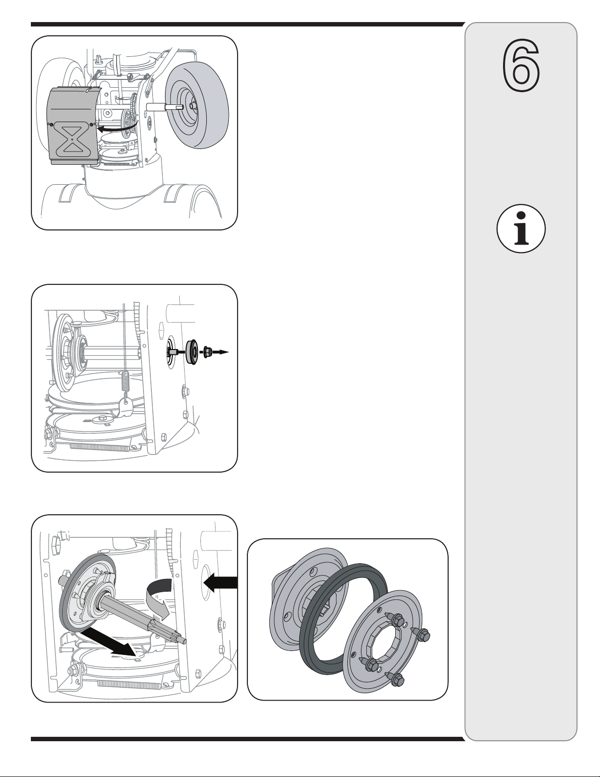
Figure 6-13
Figure 6-14
Friction Wheel Removal
If the snow thrower fails to drive with the drive control
engaged, and performing the drive control cable adjustment on page 12 fails to correct the problem, the friction
wheel may need to be replaced. Follow the instructions
below. Examine the friction wheel for signs of wear or
cracking and replace if necessary.
• Place the shift lever in third Forward (F3) position.
• Drain the gasoline from the snow thrower, or place a
piece of plastic under the gas cap.
• Carefully pivot the snow thrower up and forward so
that it rests on the auger housing.
1. a. Remove the frame cover from the underside of
the snow thrower by removing four self-tapping
screws which secure it. See Figure 6-13.
b. Remove the right-hand wheel by removing the
screw and cupped washer which secure it to the
axle.
2. Carefully remove the hex nut and washer which
secures the hex shaft to the snow thrower frame and
lightly tap the shaft’s end to dislodge the ball bearing
from the right side of the frame. See Figure 6-14.
3. Carefully position the hex shaft downward and to
the left before carefully sliding the friction wheel
assembly off the shaft. See Figure 6-15.
NOTE: If you’re replacing the friction wheel assembly
as a whole, discard the worn part and slide the new part
onto the hex shaft. Follow the steps above in reverse
order to reassemble components. If you’re disassembling the friction wheel and replacing only the rubber
ring, proceed as follows:
4. Remove the four screws which secure the friction
wheel’s side plates together. See Figure 6-16.
• Remove the rubber ring from between the plates.
• Reassemble the side plates with a new rubber ring.
• Slide the friction wheel assembly back onto the hex
shaft and follow the steps above in reverse order to
reassemble components.
6
Maintaining
Your Snow
Thrower
When reassembling
the friction wheel assembly, tighten each
screw only one rotation before turning the
wheel clockwise and
proceeding with the
next screw. Repeat
this process several
times to ensure the
plates are secured
with equal force.
NEVER replace the
auger shear pins with
standard hex pins.
Any damage to the
auger gearbox or
other components
as a result of failing
to do so will NOT be
covered by your snow
thrower’s warranty.
Figure 6-15
Figure 6-16
19

7
Off-Season
Storage
WARNING
Never store snow
thrower with fuel
in tank indoors or
in poorly ventilated
areas, where fuel
fumes may reach an
open flame, spark
or pilot light as on a
furnace, water heater,
clothes dryer or gas
appliance.
Observe the following, when preparing your snow thrower
for off-season storage:
• Drain fuel into an approved container outdoors, away
from any open flame. Allow engine to cool. Extinguish
cigarettes, cigars, pipes and other sources of ignition
prior to draining fuel. Fuel left in engine during warm
weather deteriorates and will cause serious starting
problems.
• If unit is to be stored over 30 days, prepare for storage
as instructed in the separate engine manual packed
with your unit.
• Run engine until fuel tank is empty and engine stops
due to lack of fuel.
• Remove gasoline from carburetor and fuel tank to
prevent gum deposits from forming on these parts and
causing possible malfunction of engine.
• Drain carburetor by pressing upward on bowl drain,
located below the carburetor cover.
• Fuel stabilizers, such as STA-BIL®, are an acceptable
alternative in minimizing the formation of fuel gum
deposits during storage. Do not drain carburetor if
using a fuel stabilizer.
• Wipe equipment with an oiled rag to prevent rust.
• Remove spark plug and pour one ounce of engine oil
through spark plug hole into cylinder. Cover spark plug
hole with rag. Crank engine several times to distribute
oil. Replace spark plug.
• Follow the lubrication recommendations found in the
Maintenance Section.
• Always store the snow thrower in a clean, dry area.
Drain fuel into an
approved container
outdoors, away from
any open flame. Be
certain engine is
cool. Do not smoke.
Fuel left in engine
during warm weather
deteriorates and will
cause serious
starting problems.
Do not drain
carburetor if
using fuel stabilizer.
Never use engine or
carburetor cleaning
products in the fuel
tank or permanent
damage may occur.
20

Engine fails to start
CauseProblem Remedy
1. Choke not in ON position.
2. Spark plug wire disconnected.
3. Fuel tank empty or stale fuel.
4. Engine not primed.
5. Faulty spark plug.
6. Blocked fuel line.
7. Safety key not in ignition on engine.
8. Fuel shut-ff valve closed. (If Equipped)
1. Move choke to ON position.
2. Connect wire to spark plug.
3. Fill tank with clean, fresh gasoline.
4. Prime engine as instructed in
“Operating Your Snow Thrower”.
5. Clean, adjust gap, or replace.
6. Clean fuel line.
7. Insert key fully into the switch.
8. Open fuel shut-off valve.
8
Trouble-
Shooting
Engine runs erratic
Engine overheats
Excessive
Vibration
Loss of power
1. Unit running on CHOKE.
2. Blocked fuel line or stale fuel.
3. Water or dirt in fuel system.
4. Carburetor out of adjustment.
1. Loose parts or damaged auger.
1. Spark plug wire loose.
2. Gas cap vent hole plugged.
3. Exhaust port plugged.
1. Move choke lever to OFF position.
2. Clean fuel line; fill tank with clean,
fresh gasoline.
3. Drain fuel tank. Refill with
fresh fuel.
4. Contact Service Center.
1. Contact Service Center.1. Carburetor not adjusted properly.
1. Stop engine immediately and
disconnect spark plug wire. Tighten
all bolts and nuts. If vibration
continues, have unit serviced by a
Service Center.
1. Connect and tighten spark plug
wire.
2. Remove ice and snow from gas
cap. Be certain vent hole is clear.
3. Contact Service Center.
NOTE: This section
addresses minor
service issues. For
further details,
contact customer
assistance.
Unit fails
to propel itself
Unit fails
to discharge snow
1. Drive control cable in need of adjustment.
2. Drive belt loose or damaged.
1. Chute assembly clogged.
2. Foreign object lodged in auger.
3. Auger control cable in need of adjustment.
4. Auger belt loose or damaged.
5. Shear pin(s) sheared.
21
1. Adjust drive control cable. Refer to
“Adjustments”.
2. Replace drive belt.
1. Stop engine immediately and
disconnect spark plug wire. Clean
chute assembly and inside of
auger housing with clean-out tool
or a stick.
2. Stop engine immediately and
disconnect spark plug wire.
Remove object from auger with
clean-out tool or a stick.
3. Refer to “Auger Control Test” .
4. Refer to Maintenance section.
5. Replace with new shear pin(s).

9
Warranty
Failure to comply
with suggested
maintenance
and lubrication
specifications will
void warranty.
FOUR YEAR SUPREME WARRANTY:
For four years from date of retail purchase within Canada, MTD PRODUCTS LIMITED will,
at its option, repair or replace, for the original purchaser, free of charge, any part or parts
found to be defective in material or workmanship. This warranty covers units which have
been operated and maintained in accordance with the owner’s instructions furnished with the
unit, and which have not been subject to misuse, abuse, commercial use, neglect, accident
improper maintenance or alteration. Normal wear parts or components thereof are subject to
special terms as noted below in the Ninety Day Consumer Warranty clause.
The engine, starter motor or component parts thereof carry separate warranties from their
manufacturers. Please refer to the applicable manufacturer’s warranty policy for these items.
Ninety Day Consumer Warranty on Normal Wear Parts: All normal wear part failures
will be covered on this product for a period of 90 days. After 90 days but within the four year
warranty period, normal wear part failures will be covered if caused by defects in material or
workmanship of other component parts. Normal wear parts are defined as batteries, belts,
blades, blade adaptors, grass bags, rider deck wheels, seats, tires and clutch parts (friction
wheels).
Full Ninety Day Warranty on Battery (if equipped): For ninety (90) days from the
date of retail purchase, if any battery included with this unit proves defective in material
or workmanship and our testing determines the battery will not hold a charge, MTD
PRODUCTS LIMITED will replace the battery at no charge to the original purchaser.
Additional Limited Thirty Day Warranty on Battery (if equipped): After ninety (90) days
but within one hundred twenty (120) days from the date of purchase, MTD PRODUCTS
LIMITED will replace the defective battery, for the original purchaser, for a cost of one-half
(½) of the current retail price of the battery in effect at the date of return.
Personal use: THE FOREGOING PARAGRAPHS CONSTITUTE THE MANUFACTURER’S
ENTIRE WARRANTY WITH RESPECT TO ANY PRODUCT PURCHASED AND USED
FOR PERSONAL FAMILY, HOUSEHOLD/RESIDENTIAL PURPOSES, AS DISTINGUISHED
FROM COMMERCIAL USAGE.
Commercial use: ALL APPLICATIONS OTHER THAN PERSONAL USE AS OUTLINED
ABOVE, ARE CONSIDERED COMMERCIAL USAGE.
New products purchased for commercial usage are warranted in the same manner and to the
same extend EXCEPT the term of warranty will be 90 DAYS from date of purchase.
How to Obtain Service: Warranty service is available, with proof of purchase, through
your local MTD Authorized Service Dealer. If you do not know the dealer in your area,
please write to the Service Department of MTD PRODUCTS LIMITED, P.O. BOX 1386,
KITCHENER, ONTARIO N2G 4J1. The return of a complete unit will not be accepted by the
factory unless prior written permission has been extended by MTD PRODUCTS LIMITED.
Other Warranties: All other warranties, express or implied, including any implied warranty
of merchantability is limited in its duration to that set forth in this express limited warranty.
The provisions as set forth in this warranty provide the sole and exclusive remedy of MTD
PRODUCTS LIMITED obligations arising from the sale of its products. MTD PRODUCTS
LIMITED will not be liable for incidental or consequential loss or damage.
22
12.08.06

Model Wheel As sem bly De scrip tion Tire Rim Axle
Modèle En sem ble de roue De scrip tion Roue Jante Essieu
31AE6GLF590 634-04145 16 x 4.8 x 8 LH X-Trac 734-2038 634-04173 738-04168
31AE6GLF596 634-04146 16 x 4.8 x 8 RH X-Trac 734-2038 634-04173
31AE6GLF597
31AH6KLG
31AH6NKG
31AH5IQ4 634-04136 16 x 6.5 x 8 LH X-Trac 734-2031 634-04174 738-04180
31AH5MLH 634-04137 16 x 6.5 x 8 RH X-Trac 734-2031 634-04174 738-04180
31AH5NQ5
31AE6MLG 634-04136 16 x 6.5 x 8 LH X-Trac 734-2031 634-04174 738-04168
634-04137 16 x 6.5 x 8 RH X-Trac 734-2031 634-04174 738-04168
31AS6ACE 634-04144A 13 x 4 Snow Hog 734-1732 634-04172A 738-04168
31AE6FFF 634-04141 16 x 4.8 Snow Hog 734-1530 634-04173 738-04168
31AE6FHF
31AS6LCG
31AE6GKG
31AE6MFH
31AE6MKH
31AE6LHG
31AS6FEE 634-04142A 15 X 5 Snow Hog 734-1859 634-04172A 738-04168
31AS6FEF
31AE6LHH 634-04135 16 X 6.5 Snow Hog 734-1525 634-04174 738-04168
31AE5LKH 634-04135 16 X 6.5 Snow Hog 734-1525 634-04174 738-04180
31AE63KE 634-04147A 15 X 5 X 6 LH X-Trac 734-04012 634-04172A 738-04168
31AH6DLE 634-04148A 15 X 5 X 6 RH X-Trac 634-04172A
31AH6DQ3
31AE6GLF501
7.24.07
AU GER HOUS ING COM PO NENTS/COMPOSANTS DU LOGEMENT DES TARIÈRES
SIZE
TAILLE
AU GER HOUS ING/
LOGEMENT DES
TARIÈRES
AU GER AXLE/
ESSIEU DES
TARIÈRES
SHAVE PLATE
LAME
PLATE
GEAR BOX ASS’Y/
EN SEM BLE DE LA
VIS SANS FIN
SPAC ERS/
ENTRETOISE
WORM GEAR/
ENGRENAGE
24
684-04065 711-04285 790-00120 618-04171A 731-04870 (1) 717-04449
26
684-04264 711-04284 790-00121 618-04172A 731-04870 (2) 717-04449
28
684-04268 711-04283 790-00118 618-04173A 731-04870 (3) 717-0528A
30
684-04067 711-04282 790-00119 618-04165A 731-04871 (2) 717-0528A
23

23
8
19
13
25
40
34
6
20
13
18
17
Manual Chute Control/
Commande de la goulotte
manuelle
12
14
11
7
29
26
41
22
9
4
13
21
16
5
10
6
2
13
15
28
55
4
4
30
35
38
32
33
39
16
38
31
36
37
37
7
24

REF PART
NO. NO.
N° DE N° DE
RÉF PIÈCE DE SCRIP TION DE SCRIP TION
1 631-04131B Lower Chute (2 Way) Goulotte inférieur (2 fonctions)
2 731-04861B Lower Chute (4 Way) Goulotte inférieur (4 fonctions)
3 684-04117A 2 Way Chute Con trol As sembly Ens. - commande de la goulotte à 2 fonctions
4 684-04116B 4 Way Chute Con trol As sembly Ens. - commande de la goulotte à 4 fonctions
5 710-0262 Carriage Bolt 5/16-18 x 1.50 Gr. 2 Boulon ordi naire 5/16-18 x 1,50 Qual. 2
6 710-04071 Carriage Screw 5/16-18 x 1.0 Vis ordinaire 5/16-18 x 1,0
7 710-04187 Hi-Lo Screw 1/4-15 x .5 Vis 1/4-15 x 0,5
8 710-0276 Carriage Bolt 5/16-18 x 1.00" Lg Boulon ordi naire de 5/16-18 x 1,00 po de lg
9 738-04194 Shoulder Screw .312 x 1.7:1/4-20 Vis épaulement 0,312 x 1,7:1/4-20
10 710-0895 Hex Tapp Scr 1/4 x .75" Lg. Vis taraudée à tête hex. de 1/4 x 0,75 po de lg
11 711-04469A Clevis Pin 3/8 x 1.87 Axe de chape 3/8 x 1,87
12 714-04040 Bow Tie Cot ter Pin Goupille fendue
13 712-04063 Flange Locknut 5/16-18 Gr. F Ny lon Contre-écrou à embase 5/16-18 Qual. F ny lon
14 712-03087 Wing Nut 1/4-20 Écrou en oreilles 1/4-20
15 731-04425B Upper Chute w/Ex port La bel, Re mote Goulotte sup.,étiquette d’exp., comm. a dis tance
16 731-1313C Ca ble Guide Guide de la câble
17 731-04869 Chute Flange Keeper Garde-bride de la goulotte
18 731-04912B Lower Chute Goulotte inférieur
19 741-0475 Plastic Bush ing .380 ID Manchon en plastique de 0,38 po de D.I.
20 720-0284 Han dle Knob As sem bly Bou ton
21 784-5594 Cable Bracket Chute Tilt Sup port de câble
22 712-04064 Hex L-Flanged Nut 1/4-20 Gr. F Ny lon Contre-écrou à embase 1/4-20 Qual. F ny lon
23 784-5647 Chute Crank Brkt. Support du bras de goulotte d’ejection
24 790-00131 Bracket: Chute Con trol Sup port: Commande de la goulotte
25 736-0159 Flat Washer .349 ID x .879 OD x .063 Rondelle plate 0,349 DI x 0,879 DE x 0,063
26 684-04162B Sup port Bracket Sup port
27 710-04187 Hi-Lo Screw 1/4-15 x .50 Vis 1/4-15 x 0,50
28 710-0606 Hex Hd. Cap Screw 1/4-20 x 1.5 Gr. 5 Vis à tête hex. 1/4-20 x 1,5 Qual. 5
29 710-0627 Hex Hd. Cap Screw 5/16-24 x .75 Vis à tête hex. 5/16-24 x 0,75
30 736-0463 Flat Washer .25 ID x .63 OD x .0515 Rondelle plate 0,25 DI x 0,63 x 0,0515
31 712-04064 Flange Locknut 1/4-20 Gr. F, Ny lon Contre-écrou à embase 1/4-20 Qual. F, ny lon
32 720-04039 Knob Bou ton
33 731-05307 Control Cover - 2 Way Couvercle (2 fonctions)
34 710-0451 Carriage Bolt 5/16-18 x .75 Boulon ordi naire 5/16-18 x 0,75
35 736-0413 Spring Washer .390 x .625 x .012 Rondelle ressort .390 x .625 x .012
36 738-04185 Flg Shlder Spacer .310 x .995 x 1/4-20 Entretoise epaulée 0,390 x 0,995 x 1/4-20
37 746-04238 Cable - 2 Way Câble - 2 fonctions
38 790-00200 Mounting Bracket - 2 Way Bracket - 2 fonctions
39 790-00210A Lever - 2 Way Levier - 2 fonctions
40 731-04354B Up per Chute Goulotte supérieur
31A-6004
6.22.07
25
39
33
30
24
38
18
5
25
6
31
7
28
24
13
23
46
44
23
70
46
64
68
65
80
43
7
24 30
52
58
54
63
27
7
14
57
49
47
61
61
60
58
50
41
2
1
11
4
A
A
8
26
16
29
17
3
9
56
62
59
62
35
22
7
34
32
79
45
48
67
36
19
66
2
82
55
42
40
20
10
15
12
37
72
71
30
Optional/en option
73
74
75
5
77
55
26
21
78
76
77
81
12
26

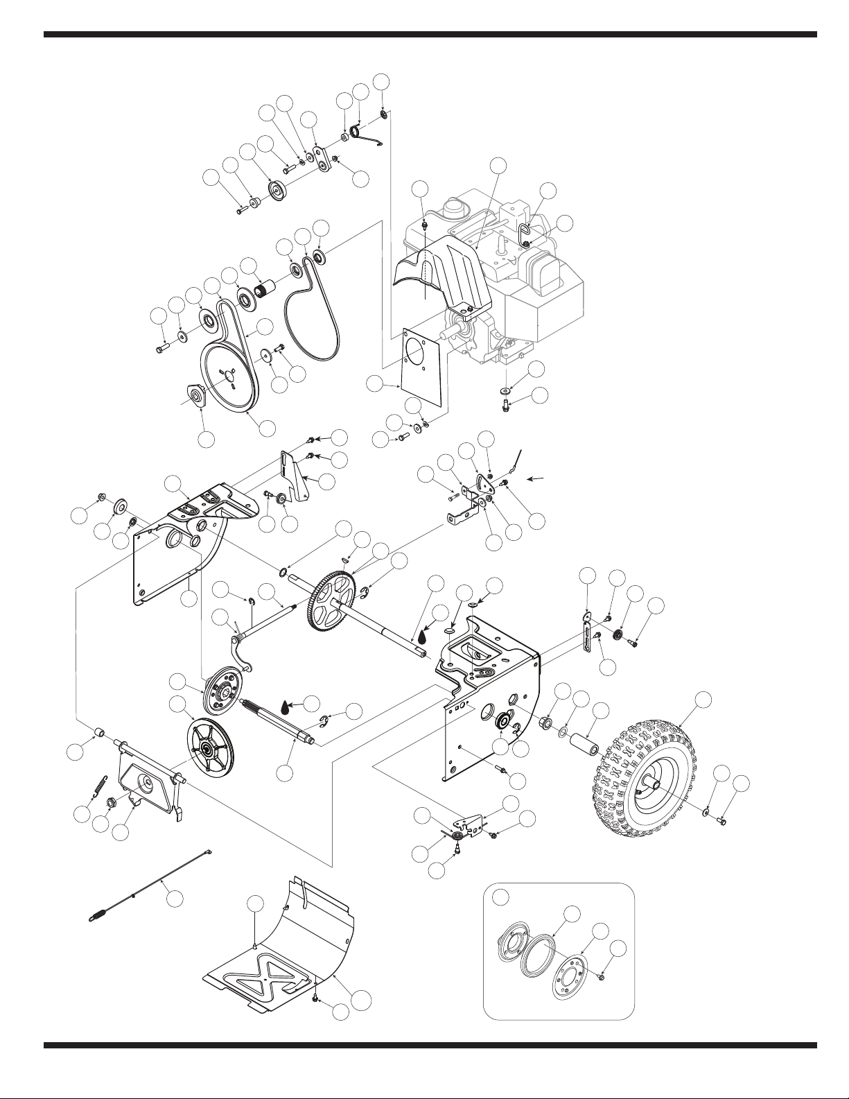
REF PART
NO. NO.
N° DE N° DE
RÉF PIÈCE DE SCRIP TION DE SCRIP TION
1 656-04025A Friction Wheel Disc As sembly Disque de roue du fric tion
2 684-04153 Friction Wheel Ass’y, Bear ing 5.5 OD Roue du friction, roulement 5,5 DE
3 684-04154 Friction Wheel Support Brkt Ass’y Support de la roue du fric tion
4 684-04156A Shift Rod Ass’y Tige de changement de la vitesses
5 710-0627 Hex L-Bolt 5/16-24 x .75 Gr. 5 Boulon hex 5/16-24 x 0,75 Qual. 5
6 710-0788 Hex Bolt 1/4-20 x 1.00 Vis à tête hex. 1/4-20 x 1,00
7 710-1652 Hex Wash Hd TT Scr. 1/4-20 x .625 Vis taraudée 1/4-20 x 0,625
8 712-04065 Flange Lock-Nut 3/8-16 Gr. F Ny lon Contre-écrou à embase 3/8-16 Qual. F ny lon
9 712-0413 Jam L-Nut 5/8-18 Gr. 5 Ny lon Écrou de blocage 5/8-18 Qual. 5 Ny lon
10 714-0126 #9 HI-Pro Key 3/16 x 3/4 Dia HT Clavette HI-Pro n°. 9 - 3/16 x 3/4 dia.
11 716-0104 Re tain ing Ring Anneau de retenue
12 716-0136 Re tainer Ring Bague de retenue
13 716-0231 “E” Ring Bague en «E»
14 717-04209A Hex Shaft .8125 - 7 tooth Arbre hex. 0,8125 - 7 dents
15 717-04230 Gear - 80 Tooth Engrenage - 80 dents
16 726-0221 Cap Speed Nut 1/4 Rod Chapeau à enfoncer
17 732-0264 Extension Spring 3/8 OD x 2.50 Ressort d’extension 3/8 DE x 2,50
18 736-0242 Cupped Washer .345 ID x .88 OD x .060 Rondelle creuse 0,345 DI x 0,88 DE x 0,060
19 736-0287 Flat Washer .79 ID x 1.25 OD x .06 Rondelle frein 0,79 DI x 1,25 DE x 0,06
20 736-04161 Flat Washer .75 x 1.00 x .06 Rondelle plate 0,75 x 1,00 x 0,06
21 737-0288 Grease Graisse
22 737-04166 Rust Pre ven ta tive Oil Huile
23 738-04184A Shoulder Screw .373 x .105:TT 1/4-20 Vis à épaulement 0,373 x 0,105:1/4-20
24 738-0924A Hex Shld.Scr.1/4-28 x .375 Vis à épaulement 1/4-28 x 0,375
25 741-0245 Hex. Flange Bear ing.751" ID Roulement à bride à six pans 0,751 DI
26 741-0563 Ball Bearing w/snap ring Roulement à billes avec bague
27 746-04229 Drive Clutch Cable 44.83" Lg. Câble de l’entraînement 44,83 po de lg.
28 746-04230 Auger Clutch Cable 47.23" Lg. Câble de la tarière 47,23 po de lg.
29 748-0190 Spacer .513 ID x 1.0 Entretoise 0,513 DI x 1,0
30 756-0625 Cable Guide Roller Guide du câble
31 790-00096 Auger Cable Guide Bracket Support, guide de la câble de la tarière
32 790-00180A Frame Bâti
33 790-00206A Guide Bracket - Au ger Cable Support - câble de tarière
34 790-00207A Guide Bracket - Drive Ca ble Support - câble de l’entraînement
35 790-00316 Frame Cover Couvercle
36 731-04873 Spacer Entretoise
37 738-04168 Axle .75 x 22" Lg. Essieu 0,75 x 22 po de lg.
38 See chart on page 23. Voir tab leau de la page 23.
39 684-04169 Idler Pul ley As sembly 1.917 OD Poulie tendeur 1,917 DE
40 710-0809 Hex Screw 1/4-20 x 1.25 Vis à tête hexagonale 1/4-20 x 1,25
41 710-0191 Hex Screw 3/8-24 x 1.25 Vis à tête hexagonale 3/8-24 x 1,25
42 710-0672 Hex Hd Cap Scr. 5/16-24 x 1.25 Gr. 5 Vis à tête hex. 5/16-24 1,25 Qual. 5
43 710-0654A Hex Wash HD Tap Scr 3/8-16 x .88 Vis autotaraudée 3/8-16 x 0,88
44 710-1245B Hex Bolt 5/16-24 x 0.875 Boulon hex. 5/16-24 x 0,875
45 710-1652 Hex Wash Hd TT Scr. 1/4-20 x .625 Vis taraudée 1/4-20 x 0,625
46 712-04064 Hex L-Flanged Nut 1/4-20 Gr. F Ny lon Contre-écrou à embase 1/4-20 Qual. F ny lon
47 726-04012 Push Nut Écrou à enfoncer
48 731-04792A Belt Cover Couvercle de la courroie
731-05353 Belt Cover (w/4 way chute con trol) Couvercle de la courroie (avec commande de la
goulotte à 4 fonctions)
49 732-04308A Torsion Spring .850 ID x .354" Lg. Ressort de tor sion 0,850 DI x 0,354 po de lg.
50 736-0247 Flat Washer .40 ID x 1.25 OD x .160 Rondelle plate 0,40 DI x 1,25 DE x 0,160
52 736-0505 Flat Washer .34 x 1.50 x .150 Rondelle plate 0,34 x 1,50 x 0,150
53 737-0318 Grease:Arctic:EP NLGI 1-58F Graisse
54 748-04053 Pul ley Adapter Adaptateur de la poulie
55 736-0119 Lockwasher 5/16 Rondelle frein 5/16
56 750-04303 Spacer .875 ID x 1.185 OD Entretoise 0,875 DI x 1,185 DE
57 750-04477 Spacer .340 x .750 x .360" Lg. Entretoise 0,340 x 0,750 x 0,360 po de lg.
58 754-04050 Belt .5 x 35.0" Lg. Courroie 0,5 x 35,0 po de lg.
59 754-0367 Belt 34.4" Lg. Courroie trapezoïdale 34,4 po de lg.
60 756-04109 Au ger Pul ley Poulie de la tarière
61 756-04113 Pul ley Half Moitié poulie
62 756-04252 Pulley Half 3/8 V x 1.71 OD Poulie, demi 1,7 DE
63 790-00208A Wheel Drive Idler Bracket Sup port
64 710-0751 Hex Bolt 1/4-20 x .62 Gr. 5 Boulon hexagonale 1/4-20 x 0,62 Qual. 5
65 712-04063 Flange Locknut 5/16-18 Gr. F, Ny lon Contre-écrou à embase 5/16-18 Qual. F, ny lon
66 735-04054 Friction Wheel Rubber Roue du friction en caou tchouc
67 732-04311 Torsion Spring .750 ID x .968" Lg. Ressort de tor sion 0,750 DI x 0,968 po de lg.
68 738-04184A Shoulder Screw .373 x .105:TT 1/4-20 Vis à épaulement 0,373 x 0,105:1/4-20
70 790-00217A Pivot Bracket Support de pivot
71 790-00218A Shift Bracket Support de changement de la vitesses
72 790-00174 Fric tion Plate Plaque du fric tion
73 748-04112A Shld. Spacer .3175 x .5 x .1025 Entretoise 0,3175 x .50 x 0,1025
74 750-04571 Spacer Entretoise
75 790-00289A Cover Plate (op tional) Plaque (en op tion)
76 732-0705 Ca ble Con trol Wire Fil de commande de la câble
77 748-0234 Shoul der Spacer Entretoise à épaulement
78 735-04100 Plug 1/2" Bouchon 1/2 po
79 735-04099 Plug 3/8" Bouchon 3/8 po
80 736-3015 Flat Washer .469 x .875 x .105 Rondelle plate 0,469 x 0,875 x 0,105
81 736-0320 Flat Washer .38 x 1.38 x .125 (Rear left hole) Rondelle plate 0,38 x 1,28 x 0,125 (arriere gauche trou)
31A-6003
6.19.07
27
30
7
35
4
2
8
25
5
21
23
12
7
18
24
43
14
22
3
9
25
1
10
16
44
7
65
7
9
17
13
4
19
15
32
33
53
57
48
55
49
60
50
51
46
47
58
54
42
45
28
52
59
56
31
29
31
33
33
41
32
27
27
27
11
11
34
27
29
29
29
20
20
34
38
33
41
40
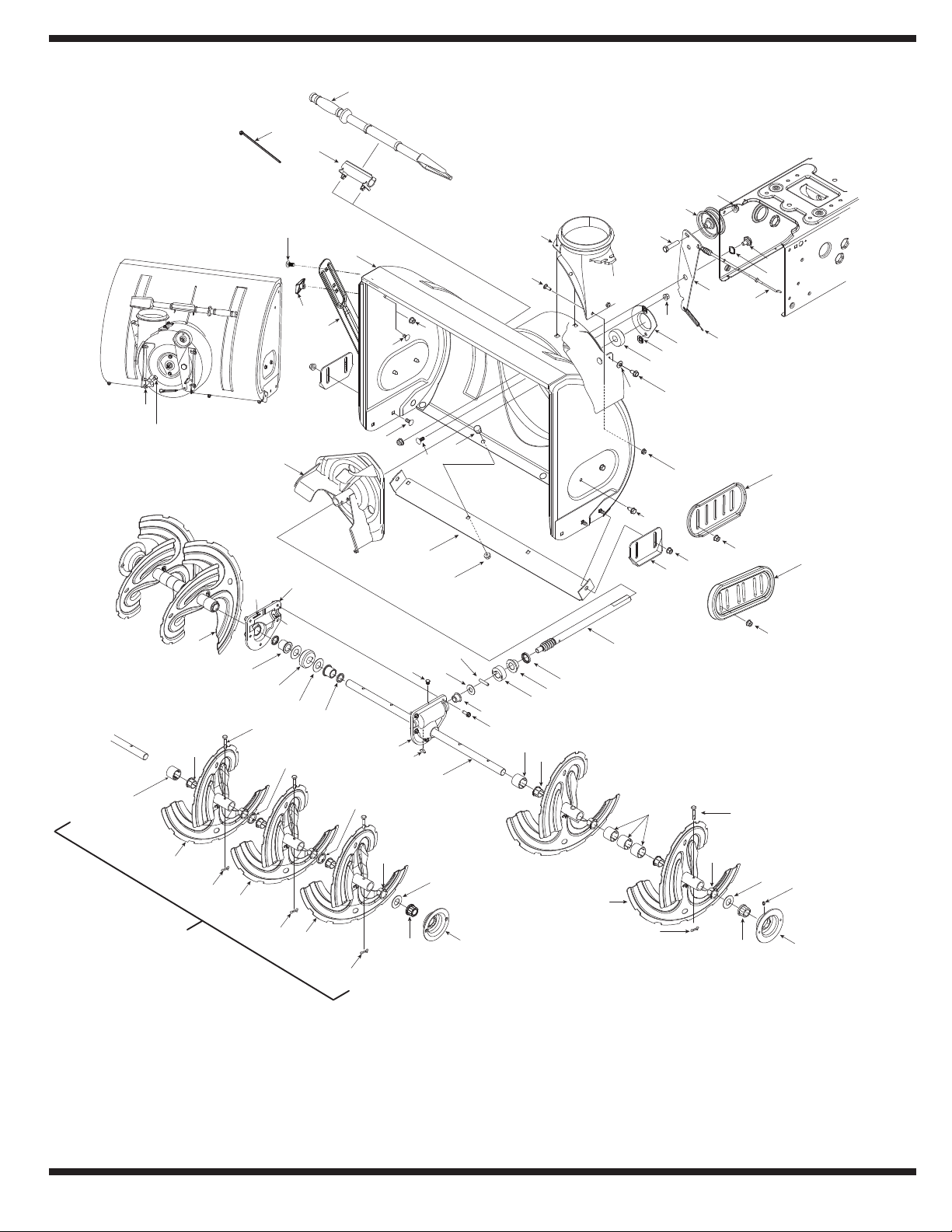
NOTE: Housing may not be exactly as shown.
REMARQUE : L'habitacle peut être légèrement
différent.
61
30 in/po
7
39
64
62
63
26
38
7
4
9
28

REF PART
NO. NO.
N° DE N° DE
RÉF PIÈCE DE SCRIP TION DE SCRIP TION
1 731-2643 Clean-Out Tool Outil de dégagement de la goulotte
2 684-04057A Impeller Ass'y 12 po Ventilateur
3 710-0347 Hex Screw 3/8-16 x 1.75 Vis à tête hex 3/8-16 x 1,75
4 710-0451 Carriage Bolt 5/16-18 x .75 Boulon ordi naire 5/16-18 x 0,75
5 710-0703 Carriage Screw 1/4-20 x .75 Gr. 5 Boulon ordi naire 1/4-20 x 0,75 Qual. 5
7 712-04063 Flange Locknut 5/16-18 Gr. F Ny lon Contre-écrou à embase 5/16-18 Qual. F ny lon
8 712-04064 Hex L-Flanged Nut 1/4-20 Gr. F Ny lon Contre-écrou à embase 1/4-20 Qual. F ny lon
9 712-04065 Hex L-Flanged Nut 3/8-16 Gr. F Ny lon Contre-ecrou à embase 3/8-16 Qual. F ny lon
10 725-0157 Ca ble Tie Attache câble
11 731-04871 Spacer 1.25 x .75 x 3/16" Lg. Entretoise 1,25 x 0,75 x 3/16 po de lg.
12 726-04012 Push-on Nut .25 dia. Écrou pousser 0,25 diam.
13 731-04705 Chute Adapter Adaptateur de goulotte d'éjection
14 732-04460 Extension Spring .38 OD x 4.59" Lg. Ressort d’extension 0,38 DE x 4,59 po de lg.
15 736-0174 Wave Washer .660 ID x .88 OD x .010 Rondelle ondulée 0,660 DI x 0,88 DE x 0,010
16 731-2635 Cleanout Tool Mount Montage de la outil de dégagement de la goulotte
17 738-0143 Shld. Scr. .500 Dia. x .335" Lg. Vis à épaulement dia. 0,500 po x 0,335 po de lg.
18 738-0281 Shoulder Scr .625 Dia x .170 Vis à épaulement dia 0,625 x 0,170 po
19 720-0284 Hand Knob Bou ton
20 741-0245 Hex. Flange Brg. .751" I.D. Roulement 0,75 DI
21 741-0309 Self-align ing bear ing Roulement auto-aligneur
22 756-0981B Flat Idler Pul ley 2.75" OD Poulie tendeur 2,75 DE
23 790-00075 Bearing Hous ing 1.85 ID Carter de la roulement 1,85 DI
24 790-00080A Auger Idler Brake Bracket Sup port
25 710-04484 Hex TT Screw 3/8-16 x .75 Vis taraudée 3/8-16 x 0,75
26 See chart on page 23. Voir tab leau de la page 23.
27 684-04107 Spiral Ass'y LH Tarière CG
28 684-04108 Spiral Ass'y RH Tarière CD
29 714-04040 Bow Tie Cotter Pin Goupille fendue
30 See chart on page 23. Voir tab leau de la page 23.
31 736-0188 Flat Washer .760 ID x 1.49 OD Rondelle plate 0,760 DI x 1,49 DE
32 738-04124A Shear Pin .25 x 1.5 Gr. 2 Goupille de cisaillement 0,25 x 1,5 po de lg
33 741-0493A Flange Bushing Collet à bride
34 790-00087A Bush ing Hous ing Carter de la col let
790-00138A Bushing Housing (w/grease fitting hole) Carter de la col let (avec trou pour raccord de graissage)
35 See chart on page 23. Voir tab leau de la page 23.
38 790-00181 Drift Cutter - Op tional Virole de réglage - en op tion
39 790-00091 Reversible Slide Shoe (steel) Patin réversible (acier)
40 737-3000 Grease Fit ting (optional) Raccord de graissage (en op tion)
41 731-04870 Spacer 1.25 x .75 x 1.00 Entretoise 1,25 x 0,75 x 1,00 po de lg.
42 741-0661A Flange Bear ing.75 ID x 1.0 OD x .975 Roulement 0,75 DI x 1,0 DE x 0,975
43 746-04230 Auger Clutch Ca ble Câble de tarière
44 784-5580 Slide Shoe Sabot coulissant
45 719-04291 RH Re duced Au ger Housing Carter de l'engrenage CD
46 719-04292 LH Re duced Auger Hous ing Carter de l'engrenage CG
47 721-0338 Oil Seal .75 x 1.0 x .125 Joint d’étanchéité d’huile 0,75 x 1,0 x 0,125
48 741-0662 Flange Bear ing .75 ID x 1.00 OD x .50 Roulement 0,75 DI x 1,00 DE x 0,50
49 710-0642 Thd Form ing Scr. 1/4-20 x .75 Vis taraudée 1/4-20 x 0,75
50 See chart on page 23. Voir tab leau de la page 23.
51 714-0161 Hi Pro Key 3/16 x 5/8 Clé 3/16 x 5/8
52 715-04021 Dowel Pin .25 OD x 1.2 Goupille 0,25 x 1,2
53 717-04126 Worm Shaft .75 OD Arbre 0,75 DE
54 See chart on page 23. Voir tab leau de la page 23.
55 718-04071 Thrust Col lar Col let
56 721-0325 Plug, 1/4 x .437 Bouchon 1/4 x 0,437
57 721-0327 Oil Seal .75 x 1 x .131 Joint d'huile 0,75 DI x 1 x 0,131
58 736-0351 Flat Washer .76 ID x 1.5 OD x .03 Rondelle plate 0,76 DI x 1,5 DE x 0,03
59 736-3084 Fl. Washer .510 x 1.120 x .060 Rondelle frein 0,510 x 1,120 x 0,060
60 741-0663 Flange Bear ing .75 ID x 1.0 OD x .925 Roulement 0,75 DI x 1,0 DE x 0,925
61 736-0242 Cupped Washer .345 ID x .88 OD x .060 Rondelle creuse 0,345 DI x 0,88 DE x 0,060
62 721-0328 Loctite Seal ant 5699 Loctite
63 737-0168 Grease - Alvania EP Lead Free Graisseur
64 731-05984 Reversible Slide Shoe (plas tic) Patin réversible (plastique)
65 710-0451 Carriage Bolt 5/16-18 x .75 (w/steel Boulon ordi naire 5/16-18 x 0,75 (avec sabot
slide shoes) coulissant acier)
710-0276 Carriage Bolt 5/16-18 x 1.0 (w/plas tic Boulon ordi naire 5/16-18 x 1,0 (avec sabot
slide shoes) coulissant acier)
31A-6002
6.21.07
29
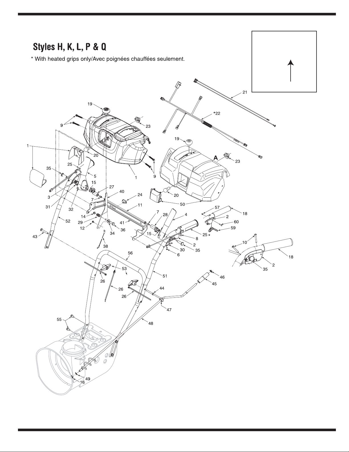
*
31AE6GKF500
Model Number/
Numéro de modèle
Style
30

REF PART
NO. NO.
N° DE N° DE
RÉF PIÈCE DE SCRIP TION DE SCRIP TION
1 631-04180 Handle Panel Ass’y - Yellow Panneau - jaune
1 631-04185 Handle Panel Ass’y - Black Panneau - noir
1 631-04183 Handle Panel Ass’y-Black w/Chute Con trol Panneau - noir avec comm. de la goulotte
2 631-04133A LH Clutch Lock Han dle Ass’y Poignée d’embrayage CG
3 631-04134B RH Clutch Lock Han dle Ass’y Poignée d’embrayage CD
4 684-04105B En gage ment Han dle As sem bly LH Poignée d’entraînement CG
5 684-04106B En gage ment Han dle As sem bly RH Poignée d’entraînement CD
6 710-04326 Screw #8-16 x .50 Vis no. 8-16 x 0,50
7 710-04354 Screw 1/4-20 x .375 Vis 1/4-20 x 0,375
8 710-0837 Oval HD C-Sunk Scr #10 x 5/8 Vis à tête goutte de suif no. 10 x 5/8
9 710-04586 Hex TT-Tap Scr 1/4-20 x 1.625 Vis taraudée 1/4-20 x 1,625
10 710-1233 Oval C-Sunk Hd Screw 10-24 x 1.375 Vis 10-24 x 1,375
11 684-04250 Pivot Rod Tige de pivot
14 712-04064 Hex L-Flanged Nut 1/4-20 Gr. F Ny lon Contre-écrou à embase 1/4-20 Qual. F ny lon
15 712-04081A Hex Shoulder Nut 1/4-20 Écrou 1/4-20
16 714-0104 Int. Cotter Pin .072 x 1.13" Lg. Goupille fendue int. 0,072 x 1,13 po de lg.
18 720-0274 Grip Poignée
19 720-04039 Shift Knob Bou ton
720-04045 Shift Knob - Yel low Bouton - jaune
20 725-04213 Lamp #1295 (w/heated grips) Ampoulle no. 1295 (avec poignées chauffées)
725-1629 Lamp Ampoulle
21 625-04039 Wire Har ness Faisceau de fil
22 725-04216A Heated Grip Wire Har ness Faisceau de fil - poignée chauffée
23 725-1649 Socket Douille
24 725-04393 Switch Contracteur
25 725-1757 Heated Grip Poignée chauffée
26 726-0470 Cable Tie 19 x 8.39" (w/plug) Attache-câble 19 x 8,39 po
725-0157 Cable Tie (w/heated grips) Attache-câble (avec poignée chauffée)
27 731-04894C Lock Plate Palastre de serrure
28 731-04896B Clutch Lock Cam Came
29 732-0193 Compression Spring .38 ID x .88 Lg Ressort de com pression 0,38 DI x 0,88 po de lg.
30 732-04219A Spring: Clutch Lock Ressort: Verrou d’embrayage
31 732-04238 Torsion Spring .8156 x .3038 Ressort de tor sion 0,8156 x 0,3038
32 735-0199A Rub ber Bumper Pare - chocs en caoutchouc
34 736-0267 Flat Washer .38 ID x .87 OD x .09 Rondelle plate 0,38 DI x 0,87 DE x 0,09
35 738-04122 Shoulder Screw 1/4-20 x 1.345 Vis à épaulement 1/4-20 x 1,345
36 738-04125 Shoulder Screw .374 Dia. x 1.05 Lg. Vis à épaulement 0,374 dia. x 1,05 po de lg.
38 746-04396 Se lec tor Speed Ca ble Câble
40 790-00311 Shift Le ver Levier de changement de la vitesse
41 790-00248A Panel Sup port Support de panneau de bord
43 710-0449 Carriage Bolt 5/16-18 x 2.25 Boulon ordinaire 5/16-18 x 2,25
44 747-04263 Chute Crank Eye Bolt Special Boulon à oeil spécial
45 720-0201A Knob 1.0 x 3.2 Bouton 1,0 x 3,20
46 726-0100 Push Nut 3/8" Rod Écrou pour tige de 3/8 po
47 735-0234 Grom met Grummet
48 684-04104 Chute Crank As sembly Manivelle de la goulotte
49 736-0185 Flat Washer .406" I.D. x .75" O.D. Rondelle plate 0,406 DI x 0,75 DE
50 631-04181 Handle Panel Ass’y - Troy-Bilt Panneau - Troy-Bilt
51 749-04142A Up per Han dle LH Goulotte supérieur CG
51 749-04191A Upper Han dle LH (Heated Grips) Guidon supérieur CG (poignée chauffée)
52 749-04141A Up per Han dle RH Guidon supérieur CD
52 749-04190A Upper Han dle RH (Heated Grips) Guidon supérieur CD (poignée chauffée)
53 720-0284 Han dle Knob As sem bly Bou ton
55 710-04484 Hex TT Screw 3/8-16 x .75 Vis taraudée 3/8-16 x 0,75
56 749-04138A Lower Han dle Guidon inférieur
57 716-04036 E Ring Bague en «E»
59 731-04913 Steer ing Con trol Commande d’orientation
60 738-04126 Pin 3/16 Goupille 3/16
31A-6006
6.22.07
31

NOTES:
For parts and/or
accessories refer to
customer support on
page 2.
Adressez-vous au
«Service après-vente»
à la page 2 pour
ce qui concerne
les pièces et/ou
accessoires.
32

NOTES:
For parts and/or
accessories refer to
customer support on
page 2.
Adressez-vous au
«Service après-vente»
à la page 2 pour
ce qui concerne
les pièces et/ou
accessoires.
33

23
accessoires.
les pièces et/ou
ce qui concerne
à la page 2 pour
«Service après-vente»
Adressez-vous au
page 2.
customer support on
accessories refer to
For parts and/or
NOTES:

22
12.08.06
de toute perte ni de tout dommage indirect ou accidentel.
LIMITED découlant de la vente de ses produits. MTD PRODUCTS LIMITED n’est pas responsable
conditions stipulées dans cette garantie représentent les seules obligations de MTD PRODUCTS
tacites de qualité marchande, se limitent à la durée stipulée dans la garantie limitée exprimée. Les
Autres garanties: Toutes les autres garanties, exprimées ou tacites, y compris les garanties
MTD PRODUCTS LIMITED.
ne peut être retournée à l’usine que si elle est accompagnée d’une autorisation écrite préalable de
MTD PRODUCTS LIMITED, C. P. 1386, KITCHENER (ONTARIO) N2G 4J1. Une machine complète
naissez pas le concessionnaire-réparateur de votre localité, adressez-vous au service après-vente,
mesure d’assurer tout service sous garantie sur présentation d’une preuve d’achat. Si vous ne conPour obtenir le service sous garantie: Tout concessionnaire-réparateur agréé par MTD est en
les mêmes conditions, MAIS pour une durée de 90 jours à compter de la date d’achat.
Les machines neuves achetées à des fins commerciales sont garanties de la même manière et dans
NELLE TELLE QUE DÉCRITE CI-DESSUS SONT CONSIDÉRÉES COMMERCIALES.
Utilisation commerciale: TOUTES LES UTILISATIONS AUTRES QUE L’UTILISATION PERSONPERSONNELLES, FAMILIALES. DOMESTIQUES/RÉSIDENTIELLES ET NON COMMERCIALES.
COMPLÈTE DU FABRICANT COUVRANT TOUTE MACHINE ACHETÉE ET UTILISÉE À DES FINS
Utilisation personnelle: LES PARAGRAPHES PRÉCÉDENTS CONSTITUENT LA GARANTIE
initial, pour la moitié (1/2) du prix de détail en vigueur de la batterie à la date du retour de celle-ci.
cent vingt (120) jours à compter de la date d’achat, à remplacer la batterie défectueuse à l’acheteur
s’engage, à l’expiration de la période de quatre-vingt-dix (90) jours et avant la fin d’une période de
Garantie limitée supplémentaire de trente jours sur la batterie (le cas échéant): MTD
maintenir une charge.
raison d’un vice de matière ou de fabrication et après que nos tests aient confirmé qu’elle ne peut
de la date d’achat au détail, toute batterie fournie avec cette machine qui s’avère défectueuse en
remplacer gratuitement à l’acheteur initial, pour une période de quatre-vingt-dix (90) jours à compter
Garantie complète de quatre-vingt-dix jours sur la batterie (le cas échéant): MTD s’engage à
frottement).
de coupe des tondeuses à siège, les sièges, les pneus et les pièces de l’embrayage (roues de
batteries, les courroies, les lames, les adaptateurs de lame, les sacs à herbe, les roues du plateau
résulte du vice de matière ou de fabrication d’une autre pièce. Par pièces courantes, on entend les
fin de la période de garantie de deux quatre, les pièces courantes sont protégées si leur défaillance
pièces courantes sont protégées pendant 90 jours. À l’expiration du délai de 90 jours, mais avant la
«Garantie de quatre-vingt-dix jours au consommateur» des pièces courantes: Toutes les
concerne ces pièces.
de leurs fabricants respectifs. Veuillez consulter les conditions de garantie du fabricant en ce qui
Le moteur, le moteur de démarrage ainsi que ses composants font l’objet d’une garantie séparée
jours au consommateur».
l’objet de conditions spéciales énumérées ci-dessous dans la clause «Garantie de quatre-vingt-dix
été accidentées et qui n’ont pas été utilisées à des fins commerciales. Les pièces courantes font
emploi incorrect ou abusif, de négligence, d’un entretien inadéquat ou de modification, qui n’ont pas
tions publiées dans la notice d’utilisation accompagnant la machine, qui n’ont pas fait l’objet d’un
s’applique seulement aux machines qui ont été utilisées et entretenues conformément aux instrucfabrication dans les quatre ans qui suivent la date d’achat au détail au Canada. Cette garantie
l’acheteur initial, la ou les pièces qui s’avèrent défectueuses en raison d’un vice de matière ou de
MTD PRODUCTS LIMITED s’engage à réparer ou à remplacer gratuitement, à son choix, à
annule la garantie.
et de lubrification
conseils d’entretien
Le non-respect des
Garantie
9
GARANTIE SUPRÊME DE QUATRE ANS

21
5. Remplacez la goupille de cisaillement.
4. Voir le Regime d’entretien.
3. Voir Test de commande de la tarière.
goulotte ou un bâton.
avec l’outil de dégagement de la
Dégagez le corps étranger de la tarière
et débranchez le fil de la bougie.
2. Arrêter immédiatement le moteur
l’intérieur du logement de la tarière.
Nettoyez la goulotte d’évacuation et
et débranchez le fil de la bougie.
1. Arrêtez immédiatement le moteur
2. Remplacez la courroie d’entraînement.
Voir le Réglages.
1.
Réglez le câble d’entraînement.
technique.
3. Adressez-vous à une station
du trou d’aération.
chapeau. Assurez-vous de la propreté
2. Dégagez la glace et la neige du
1. Branchez et serrez le fil de la bougie.
agréée.
machine par une station technique
vibrations persistent, faites vérifier la
tous les boulons et écrous. Si les
débranchez le fil de la bougie. Serrez
1. Arrêtez immédiatement le moteur et
5. Goupille de cisaillement est cisaillé.
abîmée ou ayant du jeu.
4. Courroie d’entraînement de la tarière
réglé.
3. Câble d’entraînement de la tarière mal
tarière.
2. Présence de corps étranger dans la
1. Goulotte d’évacuation bouchée.
du jeu.
2. Courroie d’entraînement abîmée ou ayant
1. Câble d’entraînement mal réglé.
3. Le port déchappement est bouché.
d’aération bouché.
2. Chapeau d’échappement du trou
1. Fil de la bougie desserré.
endommagée.
1. Pièces desserrées ou vis sans fin
la neige
La souffleuse n’évacue pas
pas
La souffleuse n’avance
Perte de puissance
Vibration excessives
8
service après-vente.
adressez-vous au
Pour plus de détails,
d’entretien mineurs.
des problèmes
chapitre concerne
REMARQUE: Ce
Dépannage
technique.
1. Addressez-vous à une station
4. Adressez-vous à une station
essence fraîche.
d’essence. Faites le plein avec une
au carburateur pour vider le réservoir
3. Débranchez la canalisation d’essence
avec une essence propre.
2. Nettoyez la canalisation; faites le plein
départ”.
1. Enlever de la position “volet de
7. Mettez la clé.
6. La nettoyer.
remplacez la bougie.
5. Nettoyez, réglez l’écartement ou
Souffleuse”.
4. Consultez le chapitre “Utilisation de la
et fraîche.
3. Faite le plein avec une essence propre
2. Branchez le fil de la bougie.
départ”.
1. Selectioner la position “volet de
1. Carbureteur est mal réglé.Moteur surchauffe
4. Carburateur est mal réglé.
3. Eau ou saleté dans le système d’essence.
essence éventée.
2. Canalisation de carburant bouchée ou
départ fermé.
1. Machine fonctionnant avec le volet de
8. Robinet d’arrivée de carburant fermé.
7. La clé de contact du moteur n’est pas mise.
6. Canalisation de carburant bouchée.
5. Bougie défectueuse.
correctement.
4. Bouton de l’amorceur n’étant pas employé
3. Réservoir vide ou essence éventée.
2. Fil de la bougie débranché.
1. Volet de départ n’est pas fermé.
Fonctionnement irrégulier
Le moteur ne démarre pas
Cause(s) Problème Solution

20
dégâts permanents.
pouvez causer des
de carburant car vous
pour nettoyer le réservoir
moteur ou du carburateur
produits de nettoyage du
rant. N’utilisez jamais des
stabilisateur de carbuteur si vous utilisez un
Ne videz pas le carbura-
démarrage.
de graves problèmes au
détériorera et causera
par temps chaud se
restant dans le réservoir
mez pas. Tout carburant
et propre.
• Entreposez toujours la souffleuse dans un endroit sec
le chapitre sur l’entretien.
• Suivez les instructions concernant la lubrification dans
bougie en place.
plusieurs fois pour bien répartir l’huile. Remettez la
le trou avec un chiffon et faites tourner le moteur
dans le trou de la bougie de la chemise. Recouvrez
• Retirez la bougie et versez une once d’huile à moteur
pour empêcher la formation de rouille.
• Essuyez la machine avec un chiffon imbibé d’huile
d’utiliser un agent de stabilisation du carburant.
remisage. Ne videz pas le carburateur si vous décidez
nimiser la formation de dépôts de gomme pendant le
par exemple) offrent une solution acceptable pour mi-
• Les agents de stabilisation du carburant (STA-BIL®
se trouve sous le couvercle du carburateur.
• Videz le carburateur en appuyant sur l’évacuation qui
raient causer le mauvais fonctionnement du moteur.
pour éviter la formation de dépôts de gomme qui pour-
• Videz toute l’essence du carburateur et du réservoir
cause de panne d’essence.
• Laissez tourner le moteur jusqu’à ce qu’il s’arrête pour
souffleuse.
la notice d’utilisation du moteur qui accompagne votre
jours, préparez-la selon les instructions fournies dans
• Si la machine doit être entreposée pendant plus de 30
de graves problèmes au démarrage.
réservoir par temps chaud se détériorera et causera
de vider le carburant. Tout carburant restant dans le
éteignez toute source de chaleur incandescente avant
surez-vous que le moteur a refroidi. Ne fumez pas et
homologué, à distance de toute flamme nue. As-
• Videz le carburant à l’extérieur dans un récipient
de la remiser.
Procédez comme suit pour préparer la souffleuse avant
7
moteur a refroidi. Ne funue. Assurez-vous que le
distance de toute flamme
récipient homologué, à
l’extérieur dans un
Videz le carburant à
gaz.
linge ou autre appareil à
un fourneau, un sêchechauffe-eau, un radiateur,
étincelle ou veilleuse d’un
avec une flamme ou une
peuvent venir en contact
vapeurs de carburant
pas adéquate et si les
si la ventilation n’est
des endroits fermés
l’intérieur ou dans
dans le réservoir à
moteur avec du carburant
N’entreposez jamais le
AVERTISSEMENT
hors saison
Remisage

19
souffleuse.
par la garantie de la
ne sera pas couvert
boulons ordinaires
par l’utilisation de
composantes, causé
leurs autres pièces
aux tarières, ou à
ordinaires. Tout dégât
par des boulons hex.
lement des tarières
les boulons de cisailNe remplacez JAMAIS
manière égale.
toutes serrées de
que les plaques soient
plusieurs fois pour
suivante. Répétez
puis passez à la vis
aiguilles d’une montre,
roue dans le sens des
de faire tourner la
à chaque vis avant
donnez un seul tour
roue de frottement,
Pour remonter la
d’entretien
Régime
6
Figure 6-16
Figure 6-15
Figure 6-14
l’ordre inverse pour remonter tous les éléments.
hexagonal et suivez les instructions ci-dessus dans
• Glissez à nouveau la roue de frottement sur l’arbre
caoutchouc neuve.
• Remontez les plaques latérales avec une bague en
les plaques.
• Retirez la bague en caoutchouc qui se trouve entre
latérales de la roue de frottement. Voir la Figure 6-16.
4. Enlevez les quatre vis qui maintiennent les plaques
caoutchouc, procédez comme suit :
roue de frottement et ne remplacez que la bague en
à nouveau les divers éléments. Si vous démontez la
tions ci-dessus dans l’ordre inverse pour assembler
pièce neuve sur l’arbre hexagonal. Suivez les instrucde la roue de frottement, jetez la pièce usée et glissez la
REMARQUE : Si vous remplacez l’ensemble complet
de l’arbre. Voir la Figure 6-15.
gauche avant de faire glisser la roue de frottement
3. Abaissez doucement l’arbre hexagonal vers la
droit du châssis. Voir la Figure 6-14.
de l’arbre pour dégager le roulement à billes du côté
la souffleuse et frappez doucement sur l’extrémité
qui maintiennent l’arbre hexagonal sur le châssis de
2. Retirez doucement l’écrou à six pans et la rondelle
sur l’essieu.
vis et la rondelle creuse qui la maintiennent
b. Démontez la roue de droite en enlevant la
taraudeuses qui le maintiennent en place.
la souffleuse en retirant les quatre vis auto-
1. a.
Démontez le couvre-châssis du dessous de
la faire reposer sur l’habitacle de la tarière.
• Basculez doucement la souffleuse vers l’avant pour
d’essence.
placez un morceau de plastique sous le bouchon
• Videz le réservoir d’essence de la souffleuse ou
marche avant.
• Placez le levier de vitesses à la 3e position de
Figure 6-13
frottement et remplacez-la au besoin.
a aucun signe d’usure ou de fendillement sur la roue de
Suivez les instructions ci-dessous. Assurez-vous qu’il n’y
lème, il faudra peut-être remplacer la roue de frottement.
expliqué à la page 12 ne parvient pas à corriger le probenclenchée, et si l’ajustement du câble de commande
Si la souffleuse n’avance pas lorsque la commande est
Démontage de la roue de frottement

18
c
b
a
Figure 6-12
procédant dans l’ordre inverse.
• Retirez la courroie et installez la courroie neuve en
roue de frottement.
l’espace entre la roue de frottement et le disque de la
4. Dégagez la courroie de transmission de la poulie et de
motrice.
c. Dégagez la courroie de transmission de la poulie
motrice.
b. Dégagez la courroie de la tarière de la poulie
vers la droite. Voir la Figure 6-11.
3. a. Utilisez une clé pour pivoter la poulie de tension
qui le maintiennent en place.
souffleuse en retirant les quatre vis auto-taraudeuses
2. Démontez le couvre-châssis du dessous de la
6-10.
faire reposer sur l’habitacle de la tarière. Voir la Figure
• Basculez doucement la souffleuse vers l’avant pour la
d’essence.
placez un morceau de plastique sous le bouchon
• Videz le réservoir d’essence de la souffleuse ou
Voir la Figure 6-9.
du moteur en enlevant les deux vis auto-taraudeuses.
1. Retirez le couvre-courroie en plastique sur le devant
de la souffleuse, procédez comme suit :
Pour démonter et remplacer la courroie de transmission
transmission
Remplacement de la courroie de
goupilles neufs.
lubrifiant à base d’huile sur l’arbre avant d’installer les
fendues de rechange sont fournis. Vaporisez un
est. Deux goupilles de cisaillement et deux goupille
se sont cisaillés. Remplacez les goupilles si besoin
• Si les tarières ne tournent pas, vérifiez si les goupilles
Figure 6-11
Figure 6-10
Figure 6-9
de glace.
cisailler si la souffleuse heurte un objet ou un bloc
la tarière. Les goupilles sont sensés de peut être
fendue mainteiennent les tarières sur l’arbre de
souffleuse.
par la garantie de la
ne sera pas couvert
boulons ordinaires
par l’utilisation de
composantes, causé
leurs autres pièces
aux tarières, ou à
ordinaires. Tout dégât
par des boulons hex.
lement des tarières
les boulons de cisailNe remplacez JAMAIS
d’entretien
Régime
6
• Deux goupilles de cisaillement et deux goupille
Tarières

17
IMPORTANT
commercial.
métallique et un solvant
Utilisez une brosse
au jet de sable.
nettoyez pas la bougie
REMARQUE : Ne
d’insuffisance d’huile.
le moteur en cas
d’endommager
souvent pour éviter
niveau d’huile plus
à 32°F. Vérifiez le
température supérieure
sont utilisées à une
importante si elles
d’huile est plus
la consommation
temps froid, mais
le démarrage par
etc.) améliorent
(5W30, 10W30,
huiles multigrades
REMARQUE : Les
d’entretien
Régime
6
souffleuse.
la garantie de votre
ne sera couvert par
des boulons ordinaires
composants par utiliser
sans fin ou à d’autres
l’ensemble de la vis
Aucun dommage à
boulons ordinaires.
cisaillement avec des
les boulons de
Ne remplacez jamais
Figure 6-8
Figure 6-7
d’essence.
d’enlevez le morceau de plastique sous le bouchon
après avoir installé la courroie de la tarière neuve, et
épaulement et de raccrocher le ressort sur le châssis
REMARQUE : N’oubliez PAS de réinstaller la vis à
procédant dans l’ordre inverse.Voir la Figure 6-8.
de la tarière. Remontez la courroie de la tarière en
faites glisser la courroie en le support et la poulie
5. Dégagez la courroie de la poulie de la tarière et
b. Décrochez le ressort du support du châssis.
sert de guide-courroie. Voir la Figure 6-7.
4. a. Desserrez et retirez la vis à épaulement qui
motrice. Voir la Figure 6-6.
3. Dégagez la courroie de la tarière de la poulie
maintiennent en place. Voir la Figure 6-5.
en retirant les quatre vis auto-taraudeuses qui le
tez le couvre-châssis du dessous de la souffleuse
la faire reposer sur l’habitacle de la tarière. Démon-
2. Basculez doucement la souffleuse vers l’avant pour
bouchon d’essence.
souffleuse ou placez un morceau de plastique sous le
REMARQUE : Videz le réservoir d’essence de la
Figure 6-6
Figure 6-5
Figure 6-4
Voir la Figure 6-4.
du moteur en enlevant les deux vis auto-taraudeuses.
1. Retirez le couvre-courroie en plastique sur le devant
souffleuse, procédez comme suit ;
Pour démonter et remplacer la courroie de la tarière de la
tarière
Remplacement de la courroie de la

16
3HEAR0IN
"EARING
3PACERS
Figure 6-3
Figure 6-2
l’habitacle. Serrez à fond.
des boulons ordinaires se trouve à l’intérieur de
2. Installez la lame plate neuve en vérifiant que la tête
la souffleuse.
embase qui la maintiennent ainsi que les patins sur
1. Enlevez les boulons ordinaires et le contre-écrous à
Pour démonter la lame plate:
écrous à embase. Voir la Figure 6-3.
ordinaires (deux sur chaque côté) et les contre-
2. Remontez les nouveaux patins avec les boulons
souffleuse.
contre-écrous à embase qui les maintiennent sur la
1. Enlevez les quatre boulons ordinaires et les
Pour retirer les patins:
ment et remplacez-les au besoin.
souffleuse et ils risquent de s’user. Vérifiez-les régulièreLa lame plate et les patins sont installés sous la
Lame plate et patins
extrémité de l’arbre de la tarière. Voir la Figure 6-2.
Lubrifiez aussi les roulements à bride trouvés à chaque
lubrifiant à l’intérieur de l’arbre et autour des entretoises.
tarière, au moins une fois par saison. Vaporisez un
Enlevez les goupilles de cisaillement sur l’arbre de la
Arbre de la tarière
aluminum.
d’entraînement en
tchouc et sur la plque
frottement en caoul’huile sur la roue de
de la graisse ou de
Évitez de répandre
paraffine ou de l’huile «3 in 1» une fois par saison.
vaseline, de l’huile de lin, de l’huile minérale, de la
Le levier de commande doit être lubrifié avec de la
Commande de direction de la goulotte
immobilisées.
les pièces se soient
Attendez que toutes
la souffleuse.
automobile à usages multiples.
roues, nettoyez et enduisez les essieux d’une graisse
des roues au moins une fois par saison. Démontez les
Huilez ou vaporisez du lubrifiant sur les roulements
Roues
d’entraînement en aluminium.
roue de frottement en caoutchouc ou sur la plaque
REMARQUE: Évitez de renverser de l’huile sur la
parer ou d’inspecter
de lubrifier, de rérêtez le moteur avant
commandes et arDébrayez toutes les
AVERTISSEMENT
toutes saison sur l’arbre hex. Voir la Figure 6-1.
Figure 6-1
3. Appliquez une légère couche d’huile polyvalente
auto-taraudeuses qui le maintient.
2. Enlevez le couvre-châssis en enlevant les deux vis
la faire reposer sur l’habitacle de la tarière.
1. Basculez doucement la souffleuse vers l’avant pour
fois par saison ou toutes les 25 heures d’utilisation.
Lubrifiez l’arbre de transmission (hex.) au moins une
Arbre de transmission
la souffleuse.
Consultez la notice d’utilisation du moteur, fournie avec
Moteur
d’entretien
Régime
Lubrification
6
moteur.
la souffleuse quant aux instructions d’entretien du
Consultez la notice d’utilisation du moteur fournie avec
Moteur
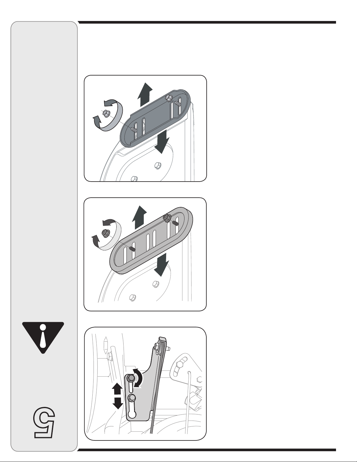
15
Réglages
5
la lame plate.
maximal entre le sol et
surer un dégagement
plus haute pour aspatins à la position la
réglez les patins à la
recouverte de gravier,
fleuse sur une surface
devez utiliser la soufquelconque, vous
Si pour une raison
matériels.
relles et des dégats
des blessures corpotarière, peut causer
s’il est projeté par la
verte de gravier qui,
sur une surface recoud’utiliser la souffleuse
Il est déconseillé
AVERTISSEMENT
Figure 5-3
Figure 5-5 - Patins réversible en acier
page 13, pour ajuster la tarière.
Reportez-vous au test de la commande de la tarière,
Commande de la tarière
vers l’avant de la souffleuse. Voir la Figure 5-5.
aussi être intervertis. Le “A” sur la pièce doit être orienté
leur durée de vie. Si les patins sont retournés, ils doivent
ultra-robustes qui peuvent être retournés pour accroître
REMARQUE: Certains modèles sont équipés de patins
3. Serrez les boulons et les écrous à fond.
usure inégale.
de niveau et en contact avec le sol pour éviter leur
2. Vérifiez que toute la surface inférieure des patins est
voulue. Voir les Figures 5-4 ou 5-5.
boulons ordinaires. Placez les patins à la position
Figure 5-4 - Patins réversible en plastique
écrous à embase (deux de chaque côté) et les
1. Ajustez les patins en desserrant les quatre contre-
surface à déblayer est irrégulière.
Utilisez les positions intermédiaire ou base lorsque la
placez les patins à la position plus haute sur l’habitacle.
ajustant les patins. Pour déblayer complètement la neige,
L’espace entre la lame plate et le sol peut être ajusté en
Patins
cas échéant.
plastique qui se trouve sous le bouchon d’essence, le
REMARQUE : N’oubliez pas de retirer le morceau de
à la position de fonctionnement.
5. Replacez le couvre-châssis et redressez la souffleuse
correcte.
pans inférieur pour maintenir le support à la position
le besoin. Voir la Figure 5-4. Serrez l’écrou à sic
transmission et relevez (ou abaissez) le support selon
six pans inférieur sur le support indexé du câble de
4. Si un réglage est nécessaire, desserrez l’écrou à
Voir la Figure 6-8.
de frottement est en contact avec la poulie motrice.
3. Embrayez la commande et assurez-vous que la roue
soit la position du levier de vitesses.
frottement et la poulie de transmission, quelle que
qu’il y a un espace de 1/8e de po entre la roue de
2. Lâchez la commande de transmission et vérifiez
taraudeuses. Voir la Figure 6-5 à la page 17.
du dessous de la souffleuse en retirant les vis autoa déjà été utilisée.), puis démontez le couvre-châssis
plastique sous le bouchon d’essence si la souffleuse
le réservoir d’essence ou avoir placé un morceau de
1. Basculez la souffleuse vers l’avant (après avoir vidé
suivante:
Pour pouvez aussi vérifier l’ajustement de la façon

14
7. Resserrez le contre-écrou à six pans inférieur.
câble.)
de jeu (ou vers le bas pour augmenter la tension du
6. Redressez le support vers le haut pour obtenir plus
support du câble de la transmission. Voir la Figure 5-3.
5. Desserrez le contre-écrou à six pans inférieur sur le
la transmission. Continuez comme suit:
4. Si l’un des tests ci-dessus échoue, ajustez le câble de
aucune résistance dans le levier de vitesses.
entre les positions R2 et F6. Vous ne devez sentir
plusieurs fois le levier de vitesses d’avant en arrière
3. Débrayez la commande de la transmission, déplacez
machine doit PAS bouger facilement.
une résistance. Les roues ne doivent pas tourner. La
déplacer la souffleuse vers l’avant. Vous devez sentir
2. Embrayez la commande de traction et essayez de
facilement.
la souffleuse, puis tirez-la. La machine doit bouger
1. La commande de transmission débrayée, poussez
comme suit:
Vérifiez l’ajustement de la commande de la transmission
«relevée». Le câble ne doit PAS être tendu.
mande de la transmission est débrayée et en position
Le câble doit présenter très peu de jeu quand la com-
Figure 5-2
levier de vitesses
Commande de la transmission et
câbles de chaque pair. Voir la Figure 5-2.
2. Ajustez également des deux côtés en réglant les deux
serrez l’écrou inférieur sur le câble.
1. Pour serrer le câble, desserrez l’écrou supérieur et
Pour faire l’ajustement, procédez comme suit:
mande de la goulotte.
inclinaison, il faudra ajuster les quatre câbles de compas coomplètement ou s’il n’est pas possible d’ajuster son
selon ce qui survient d’abord. Si la goulotte ne tourne
par saison ou toutes les 25 heures de fonctionnement,
Vérifiez que les câbles ne se sont pas détendus une fois
Figure 5-1
Commande de la goulotte
d’utilisation.
ciales dans la notice
d’instructions spétourne, sauf en cas
que le moteur
quelconque pendant
d’effectuer un réglage
N’essayez jamais
fonctionnement.
ce notice avant le
machine et dans
consignes sur la
instructions et les
et suivez toutes les
Lisez, comprenez,
AVERTISSEMENT
5. Vérifiez les réglages avant d’utiliser la souffleuse.
4. Resserrez l’écrou à six pans.
dans le câble.
3. Abaissez le support vers le bas pour éliminer tout jeu
câble de changement de vitesses. Voir la Figure 5-1.
2. Desserrez l’écrou à six pans sur le support indexé du
avant la plus rapide.
1. Placez le levier de vitesses à la position de la marche
effectuez les réglages suivants :
(avant et arrière), consultez les illustrations sur la droite et
Si vous ne pouvez utiliser toute la gamme des vitesses
Réglages
5
Câble de changement de vitesses

13
souffleuse.
la transmission de la
l’usure prématurée de
Ceci pourrait causer
arrêté la souffleuse.
avoir complètement
de la transmission et
brayé la commande
avoir au préalable dédéplacement) sans
vitesse ou de sens de
(pour changer de
le levier de vitesses
Ne déplacez JAMAIS
vous soyez habitué.
lente jusqu’à ce que
Utilisez une vitesse
main.
dans la goulotte à la
près de la tarière ou
la neige ou la glace
Ne dégagez jamais
toucher.
(65°C). Évitez de les
dépasser 150°F
zones voisines peut
silencieux et des
La température du
AVERTISSEMENT
souffleuse
de la
Utilisation
4
Figure 4-2
poignées doivent être débrayées.
la tarière et les roues. Pour arrêter la tarière les deux
4. Lâchez la commande de la transmission pour arrêter
que la commande de la transmission soit débrayée.
de blocage maintient la tarière engagée jusqu’à ce
3. Débrayez la commande de la tarière ; le mécanisme
neige.
puisse orienter la goulotte sans cesser de projeter la
la commande de la tarière pour permettre au conducteur
REMARQUE: Cette même poignée permet de bloquer
embrayée.
vitesse quand la commande de la transmission est
avancer. Lâcher-la pour arrêter. Ne changez pas de
mande de la tarière.
10. Répétez le test pour vérifier l’ajustement de la com-
supérieur.
9. Resserrez ensuite le contre-écrou à six pans
jeu (ou vers le bas pour augmenter la tension).
8. Redressez le support vers le haut pour obtenir plus de
4-2.
support de la commande de la tarière. Voir la Figure
desserrez le contre-écrou à six pans supérieur du
7. Pour ajuster à nouveau le câble de commande,
d’ajuster à nouveau le câble de la tarière.
que TOUTES les pièces se soient immobilisées avant
la position de conduite et arrêtez le moteur. Attendez
complètement immobile, retournez immédiatement à
qu’aucune pièce ne bouge. Si la tarière n’est pas
6. Vérifiez que la tarière est totalement immobilisée et
machine.
débrayée et « relevée ». Placez-vous devant la
la manette de commande de la tarière à la position
5. Laissez tourner le moteur à plein régime et gardez
tarière. Répétez cette opération plusieurs fois.
4. Attendez environ dix secondes avant de débrayer la
souffleuse) et enclenchez la tarière.
3. Tenez-vous à la position de conduite (derrière la
l’obturateur est réglé à la position rapide.
«pour faire démarrer le moteur». Vérifiez que
souffleuse selon les instructions dans le paragraphe
2. Choisissez un endroit bien aéré et faites démarrer la
SANS toutefois être tendu.
«relevée». Le câble doit présenter très peu de jeu
1. Débrayez la commande et placez-la en position
suivante :
Vérifiez le réglage de cette commande de la façon
première fois et au début de chaque saison d’hiver.
Faites ce test avant d’utiliser la souffleuse pour la
Test de la commande de la tarière
pressez la commande de la transmission pour
2. Alors que la commande de la tarière est embrayée,
la poignée pour arrêter les tarières.
gauche de la tarière contre le guidon gauche. Lâchez
projeter la neige, pressez la poignée d’embrayage
1. Pour embrayer les tarières et pour commencer à
Pour embrayer les tarières
pour arrêter.
guidon droite pour avancer la souffleuse; lâchez-la
2. Pressez la commande de la transmission contre le
adaptée aux conditions présentes.
positions de marche arrière (R). Choisissez la vitesse
positions de marche avant (F) ou à l’une des deux
le levier de changement de vitesse à l’une des six
1. Avec l’obturateur à la position Fast (lapin), placez
Pour embrayer la transmission
Déplacez celle-ci plusieurs fois.
carburateur et près des manettes de commande.
4. Enlevez toute la neige et l’humidité du couvercle du
pas possible de faire démarrer le moteur sans la clé.
REMARQUE: Rangez la clé dans un endroit sùr. Il n’est
empêcher l’utilisation non autorisée de l’équipement.
3. Retirez la clé de contact (sans tourner la clé) pour
2. Placez la manette de l’obturateur à la position STOP.
pas d’endommager le moteur.
reprises. Vous entendrez un claquement qui ne risque
ment sur la corde du démarreur à trois ou quatre
1. Quand le moteur tourne, tirez rapidement et ferme-
Démarreur à lanceur
pas possible de faire démarrer le moteur sans la clé.
REMARQUE: Rangez la clé dans un endroit sùr. Il n’est
Déplacez celle-ci plusieurs fois.
carburateur et près des manettes de commande.
6. Enlevez toute la neige et l’humidité du couvercle du
12
empêcher l’utilisation non autorisée de l’équipement.
5. Retirez la clé de contact (sans tourner la clé) pour
4. Placez la manette de l’obturateur à la position STOP.
souffleuse.
courant avant de débrancher l’autre extrémité de la
3. Débranchez d’abord le fil électrique de la prise de
du moteur.
démarreur ne risque pas d’endommager le démarreur
quelques secondes. le bruit particulier émis par le
démarreur et faites tourner le démarreur pendant
2. Quand le moteur tourne, appuyez sur le bouton du
dans une prise de courant de 120 volts C.A.
trique, sur le moteur. Branchez l’autre extrémité du fil
1. Branchez le fil électrique dans le démarreur élec-
Démarreur électrique (sur certains modèles)
comme suit avant d’arrêter le moteur:
• Pour empêcher le démarreur de geler, procédez
pour sécher toute l’humidité qui aurait pu s’y accumuler.
Laissez tourner le moteur pendant quelques minutes
Arrêt du moteur
VOLET.
PLEIN, puis revenez lentement à la position SANS
le bouton du volet de départ à la position VOLET
SANS VOLET. Si le moteur hésite, tournez à nouveau
lentement le bouton du volet de départ vers la position
5. Au fur et à mesure que le moteur chauffe, tournez
laissez-la s’enrouler lentement tout en le retenant.
poignée revenir brusquement contre le moteur, mais
4. Tirez à nouveau, mais rapidement. Ne laissez pas la
résistance. Laissez la corde s’enrouler lentement.
lanceur jusqu’à ce que vous sentiez une légère
3. Tirez lentement sur la poignée du démarreur à
nécessaire si la température est inférieure à 15ºF (-9ºC).
REMARQUE: Un amorçage supplémentaire peut être
un arrêt bref.
REMARQUE: N’AMORCEZ PAS un moteur chaud après
bouton de l’amorceur en appuyant.
pour le démarrage à froid. Couvrez toujours l’évent du
2. Appuyez deux ou trois fois sur le bouton de l’amorceur
PLEIN.
de départ à la position SANS VOLET au lieu de VOLET
REMARQUE: Si le moteur est chaud, tournez le volet
VOLET PLEIN (démarrage à froid).
1. Tournez le bouton du volet de départ à la position
Démarreur à lanceur
choke control in the OFF position instead of FULL.
souffleuse.NOTE: If the engine is already warm, place
courant avant de débrancher l’autre extrémité de la
7. Débranchez d’abord le fil électrique de la prise de
SANS VOLET.
VOLET PLEIN, puis revenez lentement à la position
à nouveau le bouton du volet de départ à la position
position SANS VOLET. Si le moteur hésite, tournez
lentement le bouton du volet de départ vers la
6. Au fur et à mesure que le moteur chauffe, tournez
démarreur immédiatement.
5. Quand le moteur démarre, lâchez le bouton du
le moteur se mette en route.
4. Appuyez sur le bouton du démarreur jusqu’à ce que
un arrêt bref.
REMARQUE: N’AMORCEZ PAS un moteur chaud après
reur électrique.
aucun cas ce démarutilisé, n’utilisez en
normalement être
où le démarreur doit
à trois trous à l’endroit
s’il n’y a pas de prise
relié à la terre, mais
Si votre système est
toujours l’évent du bouton de l’amorceur en appuyant.
l’amorceur pour le démarrage à froid. Couvrez
3. Appuyez deux ou trois fois sur le bouton de
PLEIN.
de départ à la position SANS VOLET au lieu de VOLET
REMARQUE: Si le moteur est chaud, tournez le volet
VOLET PLEIN (démarrage à froid).
2. Tournez le bouton du volet de départ à la position
la terre dans un endroit bien-aéré.
prise de courant de 120 volts C.A. à trois trous mise à
moteur. Branchez l’autre extrémité du fil dans une
1. Branchez le fil électrique dans le démarreur, sur le
terre, procédez comme suit:
Si vous avez une prise de courant à trois trous relié à la
d’utiliser le démarreur électrique.
sement toutes les instructions avant
blesser le conducteur. Suivez soigneud’une décharge électrique qui pourrait
relié à la terre pour éviter la possibilité
de 120 volts, C.A. Il doit toujours être
conçu pour fonctionner sur un courant
prise électrique à trois fils et il est
option) est équipé d’un fil et d’une
AVERTISSEMENT: Ce démarreur (en
renseignez-vous auprès d’un électricien.
trois fils reliés à la terre. Si vous n’êtes pas certain,
1. Vérifiez que le câblage de votre maison comporte
modèles)
Démarreur électrique (sur certains
que la clé soit insérée dans le commutateur d’allumage.
REMARQUE: Le moteur ne peut pas démarrer à moins
qu’elle se met bien en position. Ne tournez pas la clé.
RAPIDE .Enfoncez la clé dans la fente. Assurez-vous
3. Placez la manette de l’obturateur à la position
l’entraînement sont débrayées (relâchées).
2. Assurez-vous que les commandes de la tarière et de
l’embout métallique de la bougie.
(dans la gaine en caoutchouc), est bien attachée à
que la boucle métallique, au bout du fil de la bougie
1. Branchez le fil de la bougie sur cette dernière. Vérifiez
Pour faire démarrer le moteur
Veuillez lire ces instructions attentivement.
d’utilisation du moteur qui accompagne la souffleuse.
besoin. Suivez les instructions fournies dans la notice
Vérifiez le niveau d’huile et d’essence et ajouter au
de la
4
électrique.
cas ce démarreur
n’utilisez en aucun
fils reliés à la terre,
un système à trois
maison n’est pas
Si le câblage de votre
source incandescente.
cigare ou toute autre
cigarettes ou pipe, tout
chaud. Éteignez toute
quand le moteur est
le moteur tourne ou
l’intérieur, pendant que
plein d’essence à
Ne faites jamais le
vapeurs sont explosif.
inflammable et les
est extrêmement
l’essence. L’essence
en manipulant de
Faites très attention
le fonctionnement.
et dans ce notice avant
signes sur la machine
instructions et les conet suivez toutes les
Lisez, comprenez,
AVERTISSEMENT
souffleuse
Utilisation
Pleins d’essence et d’huile
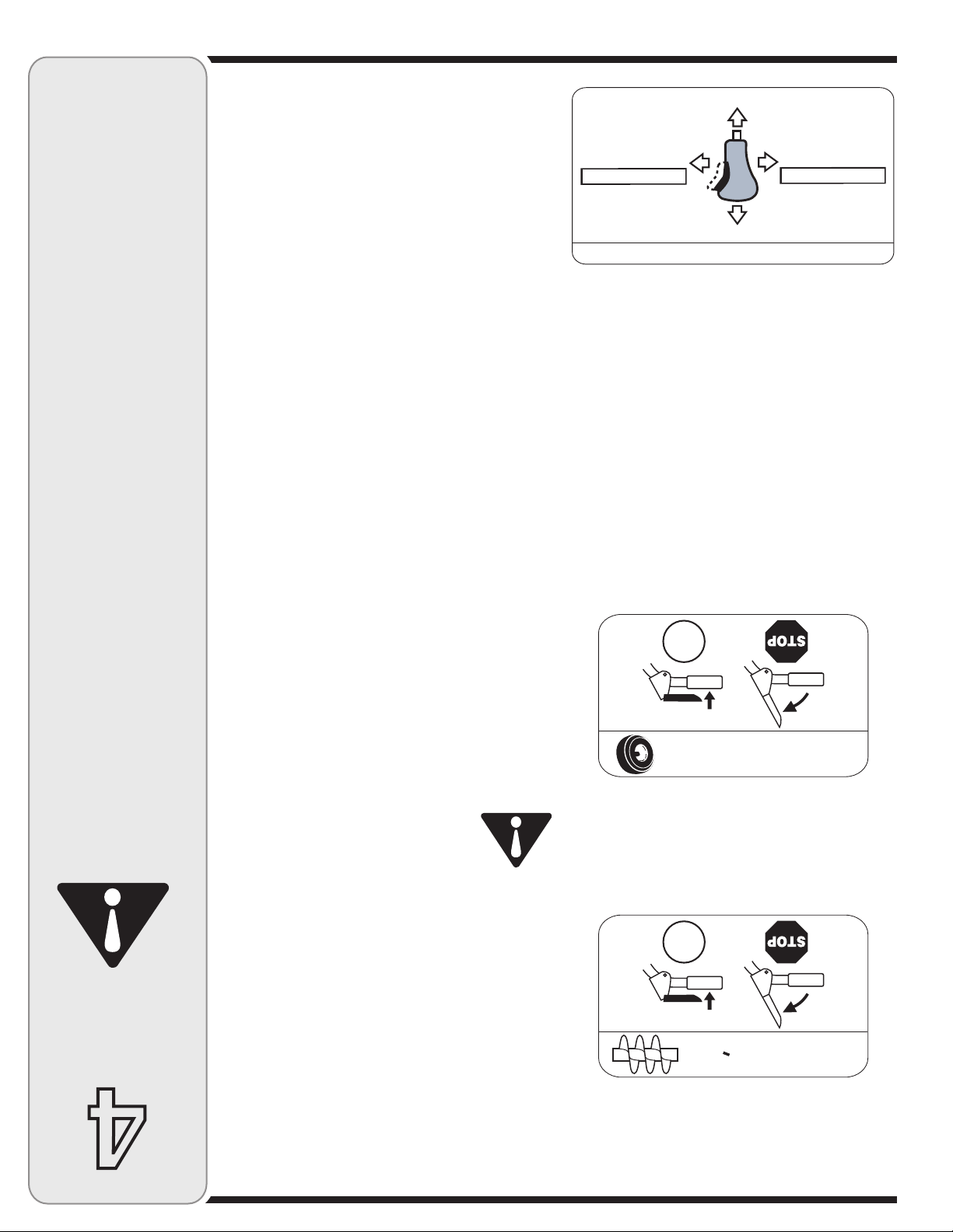
#/--!.$%
$%,!4!2)%2%
'/
#/--!.$%$%,!
42!.3-)33)/.
'/
#/--!.$%$%,!'/5,/44%
0/52!"!)3 3%2,!'/5 ,/44%
0/522%,%6 %2,!'/5, /44%
"/54/.0/5 33/)2
0/524/52. %2,!
'/5,/44%
6%23,!$2 /)4%
"/54/.0/5 33/)2
0/524/52. %2,!
'/5,/44%
6%23,!'! 5#(%
souffleuse.
du moteur et de la
pièces en mouvement
ajustés de toutes les
et vêtements non
mains, pieds, cheveux
Éloignez toujours vos
un gaz inodore mortel.
monoxyde de carbone,
moteur contiennent du
gaz d’échappement du
ou mal ventilé. Les
ou dans un local clos
le moteur à l’intérieur
faites jamais tourner
son utilisation. Ne
démarrage ou pendant
souffleuse lors du
à proximité de la
personne ne se tient
Assurez-vous que
la souffleuse.
ou tout ajustement sur
tuant toute réparation
souffleuse et en effecen travaillant avec une
lunettes de sécurité
Portez toujours des
de blessures graves.
les yeux, d’où le risque
projeter un objet vers
fonctionnement peut
en cours de
Toute souffleuse
AVERTISSEMENT
souffleuse
de la
Utilisation
4
11
dirigent la neige vers l’habitacle.
Lorsque les tarières sont embrayées, elles tournent et
Tarières
l’utilisation de la souffleuse.
Nous recommandons le port de gants ou moufles lors de
en conjonction avec des gants ou moufles appropriés.
REMARQUE: Les poignées chauffées sont à utiliser
souffleuse.
commutateur à la position «Arrêt», après avoir utilisé la
le commutateur à la position «Marche». Poussez le
la souffleuse. Pour chauffer les poignées, poussez
Il se trouve sur la droite du tableau de commande de
poignées (le cas échéant)
Commutateur de chauffage des
de neige ou de glace de la goulotte d’éjection.
pendant quelques secondes pour dégager tout reste
souffleuse) et embrayez la commande de la tarière
6. Tenez-vous au poste de conduite (derrière la
et faites démarrer la souffleuse.
de l’habitacle de la tarière. Remettez la clé de contact
5. Replacez l’outil de dégagement sur l’attache à l’arrière
goulotte.
retirer la neige ou la glace qui s’est accumulée dans la
4. Utilisez l’extrémité en forme de pelle pour déloger et
position sur l’arrière de l’habitacle de la tarière.
3. Détachez l’outil de dégagement de la goulotte de sa
l’obturateur à la position stop.
2. Arrêtez le moteur en déplacant la commande de
manette de blocage de la traction/tarière.
1. Débrayez la manette de commande de la tarière et la
dégager la goulotte.
soient immobilisées avant d’essayer de
jusqu’à ce que toutes les pièces se
le moteur et restez derrière le guidon
une goulotte bouchée à la main. Arrêtez
AVERTISSEMENT: Ne dégagez jamais
Outil de dégagement de la goulotte
N’essayez pas de tourner la clé. Elle pourrait se briser.
utilisée.
marche. Retirez la clé quand la souffleuse n’est pas
être complètement enfoncée pour mettre le moteur en
La clé de contact est un dispositif de sécurité. Elle doit
Clé de contact
correspondante de la direction des roues.
la droite ou vers la gauche, pressez sur la commande
tirez-le vers l’arrière. Pour tourner la souffleuse vers
neige, poussez le levier de commande vers l’avant ou
• Pour modifier l’angle/la distance de projection de la
tournez le levier vers la droite ou vers la gauche.
appuyez sur le bouton du levier de commande et
• Pour modifier l’orientation de la projection de la neige,
la gauche du tableau de bord.
La commande d’orientation de la goulotte se trouve sur
Commande de la goulotte à 4 fonctions
transmission avant de changer de vitesse.
IMPORTANT: Lâchez toujours la commande de la
roues s’arrêtent.
conducteur lâche les deux commandes, les tarières et les
gauche). Les tarières continueront à fonctionner. Quand le
conducteur peut lâcher la commande des tarières (sur la
en même temps que la commande de la transmission, le
de la neige. Si la commande des tarières est embrayée
l’orientation de la goulotte sans interrompre la projection
les tarières pour que le conducteur puisse changer
La commande de la transmission permet aussi de bloquer
Lâchez-la pour les arrêter.
de commande contre le guidon pour embrayer les roues.
Elle se trouve sur la droite du guidon. Serrez la manette
mission/des tarières (le cas échéant)
Blocage de la commande de trans-
pour déblayer la neige. Lâchez-la pour arrêter.
de la tarière contre le guidon pour embrayer la tarière et
Elle se trouve sur le guidon gauche. Serrez la commande
Commande de la tarière
faire le plein par le goulot de remplissage.
Il est possible de vérifier le niveau d’huile à moteur et de
Plein d’huile
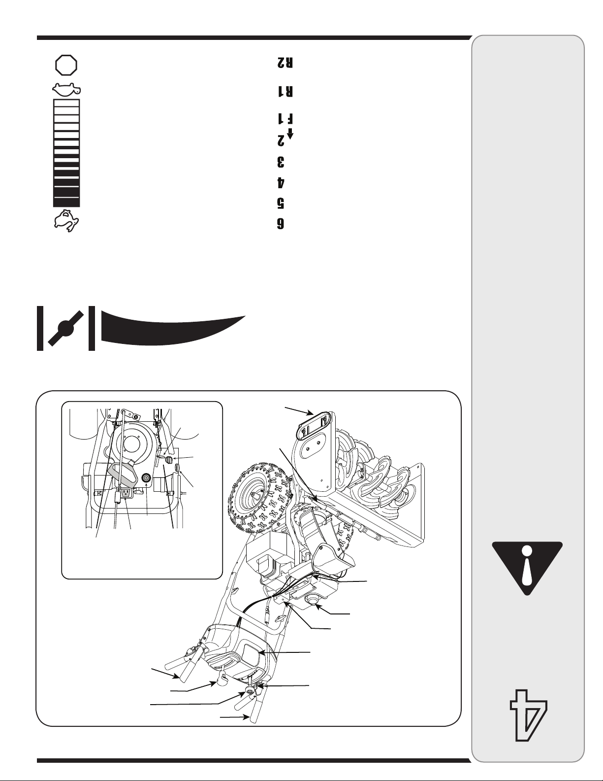
10
Phare
Commutateur de chauffage
des poignées (en option)†
† Le cas échéant
Commandes de moteur
Poignée de
démarreur
Boîte d’interrupteur
Amorceur
Clé de
contact
Volet de
départ
Commande
de
l’obturateur
Commande de la transmission
Capuchon de carburant
Plein d’huile
Bouton de démarrage électrique
Outil de
dégagement
de la
goulotte
Commande de la tarrière
Levier de vitesses
Commande de direction de la
goulotte™ à 4 fonctions
Patins
34/0
démarrer le moteur en temps froid.
carburateur du moteur pour aider à faire
force le carburant directement dans le
L’enfoncement du bouton d’amorcage
Amorçeur
abaissé complètement.
moteur et coupera le moteur quand il est
sur le moteur. Il sert a régler le régime du
La commande de l’obturateur est trouvée
l’obturateur
Commande de
moteur.
plaque sur le carburateur et facilite le démarrage du
d’une montre. Le bouton du volet de départ ferme la
activé en tournant le bouton dans le sens des aiguilles
Le volet de départ est trouvé sur l’arrière du moteur et est
Volet de départ
Figure 4-1
deux est la plus rapider.
(R2), R1 étant la plus lente des deux. et
La souffleuse a deux marches arrière
Marche arrière
position 6 la plus rapide.
(F). La position 1 est la plus lente et la
La souffleuse a six marches avant
Marche avant
de déplacement.
et sert à choisir la vitesse et la direction
Il se trouve au milieu du tableau de bord
Levier de vitesses
commandes du moteur.
plus de renseignements concernant le démarrage et les
emballée séparément avec votre souffleuse pour avoir
REMARQUE: Consultez la notice d’utilisation du moteur
nouvelle machine.
Vous pourrez ainsi bénéficier au maximum de votre
quées ci-dessous et représentées à la Figure 4-1.
commandes et diverses caractéristiques, explitravailler, il est temps de vous familiariser avec ses
Maintenant que votre souffleuse est prête à
incandescente.
toute autre source
pipe, tout cigare ou
toute cigarettes ou
est chaud. Éteignez
ou quand le moteur
que le moteur tourne
l’intérieur, pendant
plein d’essence à
Ne faites jamais le
peurs sont explosif.
inflammable et les vaest extrêmement
l’essence. L’essence
en manipulant de
Faites très attention
fonctionnement.
ce notice avant le
machine et dans
consignes sur la
instructions et les
et suivez toutes les
Lisez, comprenez,
AVERTISSEMENT
souffleuse
de la
Utilisation
Commandes de la souffleuse
4

9
façon inégale.
que de l’autre et la plaque de raclage risque de s’user de
deux pneus, la machine risque de tirer d’un côté plus
REMARQUE: Si la pression n’est pas égale dans les
du pneu.
est indiquée sur le flanc
pression recommandée
blessures graves. La
jante et causer des
l’ensemble pneu et
l’explosion de
talons peut provoquer
à l’installation des
pression excessive
tous les pneus. Une
être égale dans
pression doit toujours
bien serrée.
4. Vérifiez régulièrement que toute la boulonnerie est
marche.
ment pour maintenir la souffleuse en bon état de
3. Certains ajustements seront nécessaires périodique-
l’entretenir conformément aux instructions fournies.
de la garantie, le conducteur de la souffleuse doit
abusive ou négligente. Pour bénéficier au maximum
pas aux pièces qui ont fait l’objet d’une utilisation
2. La garantie de cette souffleuse ne s’applique
l’entretien.
1. Respectez toujours les consignes de sécurité lors de
Recommandations d’ordre général
besoin.
(ou augmentez) la pression dans les pneus selon le
fabricant est indiquée sur le flanc des pneus et réduisez
d’utiliser la souffleuse. La pression recommandée par le
Avant l’utilisation, vérifiez la pression des pneus avant
Les pneus sont gonflés excessivement pour l’expédition.
pneumatiques)
Pression des pneus (Bandages
pierre concassée. Consultez le chapitre «Réglages».
travailler sur des surfaces recouvertes de gravier ou de
Redressez-les si la neige est tassée et abaissez-les pour
Positionnez les patins en fonction de la surface de travail.
Patins
par le fabricant. La
pression recommandée
Figure 3-10
Ne dépassez jamais la
IMPORTANT
main.
dans la goulotte à la
près de la tarière ou
la neige ou la glace
Ne dégagez jamais
AVERTISSEMENT
3
à lanceur.
éviter toute interférence avec la poignée du démarreur
détendue du faisceau de câbles dans l’attache pour
le trou du guidon inférieur. Faites passer la partie
câbles sur le guidon inférieur doit être enfoncée dans
La borne sur l’attache qui maintient le faisceau de
(le cas échéant)
Faisceau de câblage du phare
Figure 3-9
ou dans la goulotte à la main.
la neige ou la glace près de la tarière
AVERTISSEMENT: Ne dégagez jamais
souffleuse en marche.
à l’usine. Coupez l’attache-câble avant de mettre la
de montage
Instructions
attache-câble sur l’arrière de l’habitacle de la tarière
REMARQUE: Cette pièce est a été fixée avec un
outil.
la page 11 pour plus de renseignement concernant cet
L’outil sert à dégager une goulotte bouchée. Consultez
le dessus de l’habitacle de la tarière avec une attache.
Un outil de dégagement de la goulotte est maintenu sur
de la goulotte
dégagement
Outil de
Outil de dégagement de la goulotte
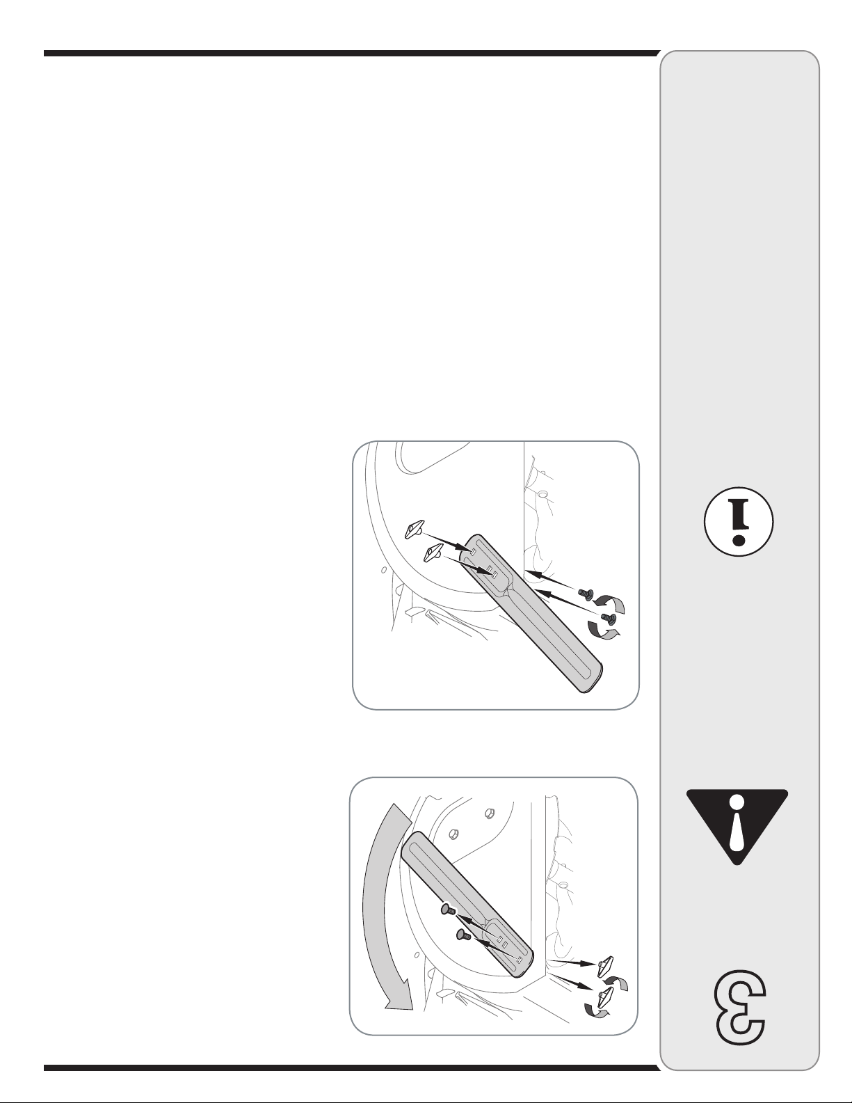
8
du pneu.
est indiquée sur le flanc
pression recommandée
blessures graves. La
jante et causer des
l’ensemble pneu et
l’explosion de
talons peut provoquer
à l’installation des
pression excessive
tous les pneus. Une
être égale dans
pression doit toujours
par le fabricant. La
Figure 3-8
pression recommandée
Ne dépassez jamais la
IMPORTANT
main.
dans la goulotte à la
près de la tarière ou
Tous les modèles OEM 390-679
Modèle de souffleuse Barres de coupe
gnement concernant le prix et la disponibilité en stock.
adressez-vous au service après-vente pour tout renseiSi votre souffleuse n’est pas équipée de barres de coupe,
attachés sur l’extérieur du logement comme illustré.
précédemment, les écrous à oreilles devraient être
Maintenez-les en place avec la boulonnerie enlevée
font face à l’avant comme illustré à la Figure 3-8.
• Positionnez les barres de coupe pour qu’elles
en place.
écrous à oreilles qui maintiennent les barres de coupe
• Enlevez les boulons ordinaires en dévissant les
des tarières. Voir la Figure 3-7.
boulonnerie sont assemblées à l’envers sur l’habitacle
• Sur les modèles si équipés, les barres de coupe et la
Elles servent en cas d’accumulation importante de neige.
Barres de coupe (le cas échéant)
Figure 3-7
3
la neige ou la glace
Ne dégagez jamais
AVERTISSEMENT
de montage
Instructions

Figure 3-6
7
Figure 3-6.
plastique pour remiser la goupille de cisaillement. Voir la
Une petite case est prévue sous le tableau de bord en
cisaillement (en option)
Remisage de la goupille de
IMPORTANT
correctement.
sans risque et
souffleuse fonctionne
pour vérifier que votre
tous les ajustements
instructions et effectuez
soigneusement les
13. Lisez et suivez
tarière» à la page
commande de la
vous à «Test de la
souffleuse, référezAvant d’utiliser votre
AVERTISSEMENT
Figure 3-5
souffleuse.
ajustements pour vérifier que votre
les instructions et effectuez tous les
11. Lisez et suivez soigneusement
la commande de la tarière» à la page
souffleuse, référez-vous à «Test de
AVERTISSEMENT: Avant d’utiliser votre
l’attache-câble et jetez-le avant d’utiliser la souffleuse.
de l’habitacle de la tarière avec un attache-câble. Coupez
Pour l’expédition, le fil électrique est maintenu sur l’arrière
guide sur le dessus du moteur. Voir la Figure 3-5.
5. Vérifiez que tous les câbles sont acheminés dans le
Figure 3-4
3
de montage
Instructions
la Figure 3-4.
avec l’écrou à oreilles et la vis hex. retirés plus tôt. Voir
4. Continuez l’installation de la goulotte sur son support

6
"
!
Figure 3-3
Figure 3-2
cisaillement.
des goupilles de
du remplacement
d’utilisation à propos
de cette notice
section «Entretien»
«Tarières dans la
Consultez le chapitre
plastique du guidon).
dans le panneau en
notice d’utilisation (ou
fournies avec la
de rechange sont
de cisaillement
Deux goupilles
REMARQUE:
souffleuse.
à tous les modèles de
notice sont applicables
discutées dans ce
Pas toutes les traits
varient par le modèle.
Les traits du souffleuse
vre plusieurs modèles.
notice d’utilisation couREMARQUE: Cette
souffleuse.
de conduite, derrière la
déterminés du poste
fendue enlevés plus tôt. Voir la Figure 3-3.
son support en utilisant l’axe de chape et la goupille
3. Placez la goulotte sur sa base et attachez-la sur
vers l’avant) sur sa base.
Voir la Figure 3-2. Positionnez la goulotte (tournée
fendue et l’axe de chape sur le support de la goulotte.
sur la commande de la goulotte ainsi que la goupille
2. Retirez l’écrou à oreilles et la vis hex. qui se trouvent
supérieur sur le guidon inférieur.
b. Serrez les boutons qui maintiennent le guidon
inférieur.
3-1. Alignez le guidon supérieur avec le guidon
a. Redressez le guidon supérieur comme à la Figure
rouleaux de guidage.
inférieure de la souffleuse, sont bien alignés avec les
1. Assurez-vous que les deux câbles, sur la partie
au carburant et à l’huile à moteur à employer.
veuillez consulter la notice d’utilisation du moteur quant
plein d’huile mais SANS ESSENCE. Après l’assemblage
REMARQUE: La souffleuse a été expédiée avec le
Figure 3-1
3
de la souffleuse sont
côtés droit et gauche
REMARQUE: Les
de montage
Instructions

5
notice et sur la machine.
qui figurent dans cette
ments et instructions
respecter les avertisselire, comprendre et
personnes qui peuvent
être utilisée que par des
Cette machine ne doit
Votre responsabilité
CE SYMBOLE!
QUI ACCOMPAGNE
L’AVERTISSEMENT
RESPECTEZ
corporelles.
entraîner des blessures
ces instructions peut
Le non-respect de
servir de cette machine.
d’essayer de vous
notice d’utilisation avant
figurant dans cette
toutes les instructions
d’autrui. Prière de lire
biens, mais aussi ceux
votre personne et vos
danger non seulement
peuvent mettre en
ne sont pas respectées,
importantes qui, si elles
consignes de sécurité
votre attention sur des
Ce symbole attire
AVERTISSEMENT
sécurité
de
Consignes
2
et des blessures graves ou mortelles.
non-respect de ces recommandations peut causer des accidents
bon état de marche et ne sont pas usés de façon excessive. Le
surer que tous les dispositifs mécaniques et de sécurité sont en
chaque année par une station technique agréée pour vous asachetez une machine neuve ou faites inspecter la machine
fonctionnement. Au terme de cette durée de vie utile moyenne,
durée de vie utile moyenne de sept (7) ans, ou 60 heures de
américaine de protection de l’environnement), ce produit a une
et la “U.S. Environmental Protection Agency” (EPA - Agence
- Commission sur la sécurité des produits de consommation)
D’après la Consumer Products Safety Commission (CPSC
Durée de vie utile moyenne
Modifi cation (EM) et Three Way Catalyst (TWC) le cas échéant.
systèmes de contrôle des émissions de gaz suivants : Engine
de l’essence sans plomb ordinaire et peuvent être dotés des
équipement hors route) sont certifi és pour fonctionner avec
la Californie et de l’agence EPA fédérales pour SORE (petit
Les moteurs certifi és conformes aux normes régulatrices de
Avis concernant les émissions de gaz
réglage de l’usine du régulateur.
tionnement à des vitesses dangereuses. Ne modifi ez jamais le
provoquer l’emballement du moteur et entraîner son fonctout le moteur. Toute modifi cation du réglage du régulateur peut
Pour éviter toute blessure grave ou fatale, ne modifi ez pas du
Ne modifiez pas le moteur.
tions de remisage hors-saison.
11. Consultez toujours la notice d’utilisation quant aux instruclinge ou autre appareil à gaz).
(d’un chauffe-eau, un radiateur, un fourneau, un sèchel’intérieur s’il y a une flamme, une étincelle ou une veilleuse
10. Ne remisez jamais la machine ou les bidons d’essence à
souffleuse.
de la tarière et de la turbine ne gèle avant de remiser la
pour éliminer la neige de la tarière et éviter que l’ensemble
9. Laissez la machine fonctionner pendant quelques minutes
l’environnement.
déchets et liquides qui risquent de nuire à la nature et à
8. Respectez les règlements concernant l’élimination des
remplacez-les au besoin.
7. Prenez soin des étiquettes de sécurité et d’instructions et
«Réglages» dans la notice d’utilisation de la machine.
et faites les réglages nécessaires. Consultez le chapitre
6. Vérifiez fréquemment que les commandes fonctionnent bien
et compromettre la sécurité de l’utilisateur.
d’origine peuvent donner lieu à de mauvaises performances
ne sont pas conformes aux spécifications de l’équipement
pièces authentiques seulement. L’utilisation de pièces qui
souvent tous les composants et remplacez-les par des
s’usent avec l’usage. Par mesure de sécurité, vérifiez
5. Les plaques de raclage et les patins de la souffleuse
le moteur s’emballer, ce qui peut être dangereux.
4. Ne modifiez pas le réglage du régulateur et ne laissez pas
qu’elle n’est pas endommagée.
Examinez soigneusement la machine pour vous assurer
serrés et maintenez la machine en bon état de marche.
3. Vérifiez régulièrement que les boulons et vis sont bien
la réparation ou l’examen de la machine.
empêcher tout démarrage accidentel pendant le nettoyage,
Débranchez le fil de la bougie et mettez-le à la terre pour
que la tarière /turbine se soit complètement immobilisée.
brayez toutes les commandes et arrêtez le moteur. Attendez
2. Avant de nettoyer, de réparer ou d’examiner la machine, dénotice d’utilisation.
chapitres concernant l’entretien et les réglages dans cette
souvent qu’ils fonctionnent correctement. Consultez les
1. Ne modifiez jamais les dispositifs de sécurité. Vérifiez
Entretien et Remisage
du concessionnaire le plus proche de chez vous.
Adressez-vous au service après-vente pour obtenir le nom
qui n’ont pas été abordées par cette notice d’utilisation.
20. Faites toujours preuve de bon sens dans des situations
de la machine. (ex. poids de roues, chaînes, cabine etc.)
19. N’utilisez que des accessoires homologués par le fabricant
goulotte.
mouvement se soient immobilisées avant de déboucher la
Arrêtez le guidon jusqu’à ce que toutes les pièces en
pas la goulotte d’éjection pendant que le moteur tourne.
pour déboucher l’ouverture de la goulotte. Ne débouchez
près de l’admission. Utilisez toujours l’outil de dégagement
18. Ne placez jamais votre main dans la goulotte d’éjection ou
faire un ajustement quelconque ou d’examiner la machine.
immobilisée avant de déboucher la goulotte d’éjection, de
Attendez que la tarière/turbine se soit complètement
de quitter le poste de conduite (derrière les guidons).
17. Débrayez toutes les commandes et arrêtez le moteur avant
remettre en marche.
endommagée. Réparez tout dégât éventuel avant de la
vibrer de façon anormale. Vérifiez que la machine n’est pas
à la terre contre le moteur si la machine commence à
16. Arrêtez le moteur, débranchez le fil de la bougie et mettez-le
surfaces glissantes. Soyez prudent en reculant.
15. Ne déplacez jamais rapidement la souffleuse sur des
utilisée.
turbine pour transporter la machine et lorsqu’elle n’est pas
14. Débrayez la commande de l’ensemble de la tarière et de la
tenez fermement le guidon. Marchez, ne courrez pas.
lumière est insuffisante. Gardez toujours un bon équilibre et
13. N’utilisez pas la machine si la visibilité est mauvaise ou si la
neige trop rapidement.
12. Ne fatiquez pas la machine en essayant de déblayer la
quiconque de se tenir devant la machine.
et des animaux de compagnie et ne permettez jamais à
11. Ne dirigez jamais la neige vers des enfants, des spectateurs
matériels.
ricocher et causer des blessures graves ou des dégâts
des fenêtres, murs, voitures, etc. car les débris peuvent
10. Prévoyez de travailler en évitant de projeter la neige vers
lant sur une pente.
9. Faites très attention en changeant de direction et en travailévidents et à la circulation.
ou chemins en gravier. Faites attention aux dangers non
8. Soyez extrêmement prudent à proximité des routes, allées
peuvent causer des brûlures. Ne les touchez pas.
7. Le silencieux et le moteur deviennent très chauds et
boissons alcoolisées ou après avoir pris des médicaments.
6. Ne vous servez pas de la machine après avoir bu des
dangereux.
contiennent du monoxyde de carbone, un gaz inodore très
clos ou mal aéré car les gaz d’échappement du moteur
5. Ne faites jamais fonctionner la machine dans un local
4
Utilisation
avant de la remiser.
un sèche-linge ou autre appareil à gaz).
veilleuse (d’un chauffe-eau, un radiateur, un fourneau,
à l’intérieur s’il y a une flamme, une étincelle ou une
attendez 5 minutes avant de la remettre en marche.
sur le moteur et la machine. Déplacez la machine et
l’expansion du carburant.
espace d’un demi-pouce environ pour permettre
minutes avant de faire le plein.
d’essence pendant que le moteur tourne.
autre source incandescente.
seulement.
place et assurez-vous qu’ils sont en bon état.
endommagée. Laissez tous les dispositifs de sécurité en
4. Ne travaillez jamais sans la goulotte d’éjection ou si elle est
ment à la position de débrayage lorsqu’elles sont relâchées.
facilement dans les deux directions et revenir automatique-
3. Toutes les manettes de commande doivent fonctionner
machine et pourrait causer des blessures corporelles.
jamais son rôle ce qui rendrait dangereux l’emploi de la
de la turbine est un dispositif de sécurité. Ne contournez
2. La manette de commande de l’ensemble de la tarière et
mouvement peuvent amputer mains et pieds.
la turbine ou dans la goulotte d’éjection. Les pièces en
pièce en mouvement, dans l’habitacle de la tarière ou de
1. Ne placez jamais vos mains ou vos pieds près d’une
j. Laissez la machine refroidir pendant au moins 5 minutes
i. Ne remisez jamais la machine ou les bidons d’essence
h. En cas de débordement, essuyez toute éclaboussure
g. Resserrez bien le capuchon d’essence.
f. Ne faites jamais déborder le réservoir. Laissez un
e. Laissez le moteur refroidir pendant au moins deux
d. N’enlevez jamais le capuchon d’essence et n’ajoutez pas
c. Ne faites jamais le plein à l’intérieur.
b. Éteignez toute cigarette ou pipe, tout cigare ou toute
a. Remisez le carburant dans des bidons homologués
changez immédiatement de vêtements.
ou sur vos vêtements s’enflammaient. Rincez votre peau et
être grièvement blessé si des éclaboussures sur votre peau
inflammable et les vapeurs risquent d’exploser. Vous pouvez
en manipulant de l’essence. Il s’agit d’un produit extrêmement
Pour éliminer tout risque de blessure grave, faites très attention
Manipulation de l’essence
extérieure avant de commencer à déblayer.
8. Laissez le moteur et la machine s’habituer à la température
moins d’indications contraires de la part du fabricant).
7. N’essayez jamais de régler le moteur pendant qu’il tourne (à
moteur en marche.
avec les surfaces en gravier ou en pierre concassée.
à démarreur électrique.
à la terre avec toutes les machines équipées d’un moteur
améliorent votre stabilité sur des surfaces glissantes.
les pièces en mouvement. Portez des chaussures qui
ou de vêtements amples qui risquent de se prendre dans
adéquats. Ne portez pas de bijoux, d’écharpes longues
blesser aux yeux.
Un objet peut en effet être projeté, ricocher et vous
machine ou en effectuant un réglage ou une réparation.
ou qui risquent d’être projetés par la tarière/turbine.
fer et autres objets sur lesquels vous pourriez trébucher
tous les paillassons, traîneaux, morceaux de bois, fils de
Préparation
surtout en reculant.
s’approche.
quand elle est en marche. Arrêtez la machine si quelqu’un
enfants à une distance d’au moins 75 pieds de la machine
projeter la neige vers la route, des spectateurs, etc.
blessures graves. Prévoyez de travailler en évitant de
bien le fonctionnement de la machine de s’en servir.
s’en servir sous la surveillance étroite d’un adulte.
de sécurité. Ils doivent apprendre à utiliser la machine et
fonctionnement de la machine et respecter les consignes
doivent lire la notice d’utilisation, bien comprendre le
de se servir de la machine. Des adolescents plus âgés
les commandes.
Apprenez à arrêter la machine et à débrayer rapidement
utilisation de cette machine avant de vous en servir.
rechange.
consultation ultérieure et pour commander des pièces de
cette notice d’utilisation à un endroit sûr pour toute
d’utilisation avant de la mettre en marche. Conservez
instructions qui figurent sur la machine et dans la notice
Formation
6. Débrayez toutes les commandes avant de mettre le
5. Réglez la hauteur de l’habitacle pour éviter tout contact
notice et sur la machine.
qui figurent dans cette
ments et instructions
respecter les avertisse-
4. Utilisez une rallonge à 3 fils et une prise de courant mises
lire, comprendre et
personnes qui peuvent
être utilisée que par des
Cette machine ne doit
3. Ne travaillez pas sans porter des vêtements d’hiver
Votre responsabilité
CE SYMBOLE!
QUI ACCOMPAGNE
2. Portez toujours des lunettes de sécurité en utilisant la
L’AVERTISSEMENT
RESPECTEZ
corporelles.
1. Examinez soigneusement la zone à déblayer et enlevez
entraîner des blessures
ces instructions peut
Le non-respect de
7. Soyez toujours prudent pour ne pas glisser ou tomber,
servir de cette machine.
d’essayer de vous
notice d’utilisation avant
6. Gardez les spectateurs, les animaux de compagnie et les
figurant dans cette
toutes les instructions
d’autrui. Prière de lire
5. Les objets projetés par la machine peuvent causer des
4. Ne permettez jamais à des adultes ne connaissant pas
biens, mais aussi ceux
votre personne et vos
danger non seulement
peuvent mettre en
ne sont pas respectées,
importantes qui, si elles
3. Ne permettez jamais à des enfants de moins de 14 ans
consignes de sécurité
votre attention sur des
Ce symbole attire
AVERTISSEMENT
2. Familiarisez-vous avec les commandes et la bonne
1. Assurez-vous de lire et de bien comprendre toutes les
sécurité
corporelles graves et même mortelles.
de
et projeter des débris. Par conséquent, le non-respect de ces consignes peut causer des blessures
part de l’utilisateur peut entraîner des blessures graves. Cette machine peut amputer mains et pieds
dans la notice d’utilisation. Comme avec tout appareil motorisé, une négligence ou une erreur de la
DANGER: Cette machine doit être utilisée conformément aux consignes de sécurité qui figurent
2
des anomalies congénitales ou d’autres problèmes liés à la reproduction.
produits chimiques reconnus dans l’État de Californie comme causant le cancer,
AVERTISSEMENT: Les gaz d’échappement de ce produit contiennent des
Consignes

notice et sur la machine.
#3
qui figurent dans cette
ments et instructions
respecter les avertisselire, comprendre et
personnes qui peuvent
être utilisée que par des
Cette machine ne doit
Votre responsabilité
CE SYMBOLE!
QUI ACCOMPAGNE
L’AVERTISSEMENT
RESPECTEZ
corporelles.
entraîner des blessures
ces instructions peut
Le non-respect de
servir de cette machine.
d’essayer de vous
notice d’utilisation avant
figurant dans cette
toutes les instructions
d’autrui. Prière de lire
biens, mais aussi ceux
votre personne et vos
danger non seulement
peuvent mettre en
ne sont pas respectées,
importantes qui, si elles
consignes de sécurité
votre attention sur des
Ce symbole attire
AVERTISSEMENT
3
pour nettoyer la goulotte.
servir de l’outil de dégagement
se soient arrêtées avant de vous
jusqu’à ce que toutes les pièces
et restez derrière les guidons
la goulotte. Arrêtez le moteur
dégager une obstruction dans
servez jamais de vos mains pour
AVERTISSEMENT : Ne vous
souffleuse en marche.
l’usine. Coupez l’attache-câble avant de mettre la
Cet outil a été fixé avec un attache-câble à
cumulations de neige et de glace dans la goulotte.
avec une attache. Cet outil sert à dégager les acmaintenu sur le dessus de l’habitacle de la tarière
Un outil de dégagement de la goulotte est
de la goulotte
dégagement
Outil de
de
1
sécurité
Étiquettes

2
-4$02/$5#43,)-)4%$
+)4#(%.%2/..'*
8888888888
88888888888
-ODEL.UMBER
.UM£RODEMODÞLE
3ERIAL.UMBER
.UM£RODES£RIE
WWWMTDCANADACOM
tation.
l’emplacement de ces numéros. On vous demandera d’enregistrer le numéro de série avant de pouvoir poursuivre votre consulPréparez vos numéros de modèle et de série avant de téléphoner. Veuillez lire le chapitre précédent pour déterminer
consulter la notice d’utilisation du moteur fournie avec votre machine.
caractéristiques techniques, la garantie et le service après-vente du moteur. Pour plus de renseignements à ce sujet, veuillez
3.
Le fabricant du moteur est responsable de toutes les questions concernant les performances, la puissance indiquée, les
2. Appelez un agent du service après-vente au 1-800-668-1238.
vente.
1. Visitez le site www.yardman.ca où vous trouverez de nombreuses suggestions utiles. Cliquez sur le bouton Service après-
tionnement ou l’entretien de la machine, les spécialistes sont à votre disposition. Choisissez l’une des options ci-dessous:
Si l’assemblage de cette machine vous pose des problèmes ou pour toute question concernant les commandes, le fonc-
sans vous adresser d’abord au service après-vente.
Veuillez retourner la machine au détaillant qui vous l’a vendue,
Service après-vente
souffleuse.
poste de conduite et regardez à l’arrière du châssis de la
plaque signalétique, placez-vous derrière la souffleuse à la
de plaque signalétique fourni sur la droite. Pour localiser la
le numéro de modèle et le numéro de série sur le modèle
localiser la plaque signalétique sur l’équipement, et recopier
NOUVELLE SOUFFLEUSE,
AVANT DE PROCÉDER À L’ASSEMBLAGE DE VOTRE
Pour trouver le numéro de modèle
d’utilisation
de la version anglaise de cette notice
Pièces détachées (voir la page 23
Garantie ............................................................. 22
Dépannage ........................................................ 21
Remisage hors saison .....................................20
Entretien de la souffleuse ................................ 16
Réglages ............................................................ 14
Utilisation de la souffleuse .............................. 10
Instructions de montage .................................... 6
Important consignes de sécurité ...................... 4
Étiquettes ............................................................ 3
Table des matières
vous assurer de bien comprendre toutes les instructions.
nécessaires à l’assemblage, à la préparation et à l’entretien de votre machine. Veuillez donc la lire attentivement et
Cette notice d’utilisation est une pièce importante de votre nouvel équipement. Elle vous fournit les renseignements

06/05/07
769-03245
MTD Products Ltd., P. O. Box 1386, KITCHENER, ONTARIO N2G 4J1
IMPRIMÉ AUX ÉTATS-UNIS
DE METTRE EN MARCHE LA MACHINE.
SÉCURITÉ ET LES INSTRUCTIONS AVANT
LISEZ ATTENTIVEMENT LES RÈGLES DE
IMPORTANT:
Souffleuse à neige deux phases
NOTICE D’UTILISATION
Dépannage * Listes des pièces détachées * Garantie
Sécurité * Montage * Fonctionnement * Réglages * Entretien
 Loading...