


Operator’s Manual
PART NO. 769-00936 (1/04)
English
Straight Shaft
Electric Trimmer
Model
YM137
SAVE THESE INSTRUCTIONS DO NOT THROW AWAY

2
INTRODUCTION
Copy the serial number
here:
THANK YOU
Thank you for buying this quality product. This modern
outdoor power tool will provide many hours of useful
service. You will find it to be a great labor-saving device.
This operator’s manual provides you with easy-tounderstand operating instructions. Read the whole
manual and follow all the instructions to keep your new
outdoor power tool in top operating condition.
PRODUCT REFERENCES, ILLUSTRATIONS
AND SPECIFICATIONS
All information, illustrations, and specifications in this
manual are based on the latest product information
available at the time of printing. We reserve the right to
make changes at any time without notice.
Copyright© 2003 MTD SOUTHWEST INC, All Rights
Reserved.
SERVICE INFORMATION
Service on this unit both within and after the warranty
period should be performed only by an authorized and
approved service dealer.
For service call 1-800-345-8746, or 1-800-668-1238 in
Canada to obtain a list of authorized service dealers near
you. For more details about your unit, visit our website at
www.yardman.com.
If you have difficulty assembling this product or have any
questions regarding the controls, operation or maintenance of this unit, please call the Customer Support
Department.
DO NOT RETURN THE UNIT TO THE RETAILER.
PROOF OF PURCHASE WILL BE REQUIRED FOR
WARRANTY SERVICE.
Make sure you carefully read and understand this manual before starting or operating this equipment.
THIS PRODUCT IS COVERED BY ONE OR MORE U.S. PATENTS. OTHER PATENTS PENDING.
TABLE OF CONTENTS
Service Information . . . . . . . . . . . . . . . . . . . . . . . . .2
Rules for Safe Operation . . . . . . . . . . . . . . . . . . . . .3
Know Your Unit . . . . . . . . . . . . . . . . . . . . . . . . . . . .6
Assembly Instructions . . . . . . . . . . . . . . . . . . . . . . .7
Operating Instructions . . . . . . . . . . . . . . . . . . . . . . .8
Maintenance and Repair Instructions . . . . . . . . . . .11
Troubleshooting Chart . . . . . . . . . . . . . . . . . . . . . .14
Specifications . . . . . . . . . . . . . . . . . . . . . . . . . . . . .15
Warranty Information . . . . . . . . . . . . . . . . . . . . . . .18
Parts List . . . . . . . . . . . . . . . . . . . .Inside Back Cover
Copy the model and parent
part number here:
Before beginning, locate the unit’s model plate. It lists
the model and serial numbers of your unit. Refer to the
sample plate below and copy the information for future
reference.
MODEL :
S/N :
ITEM :

3
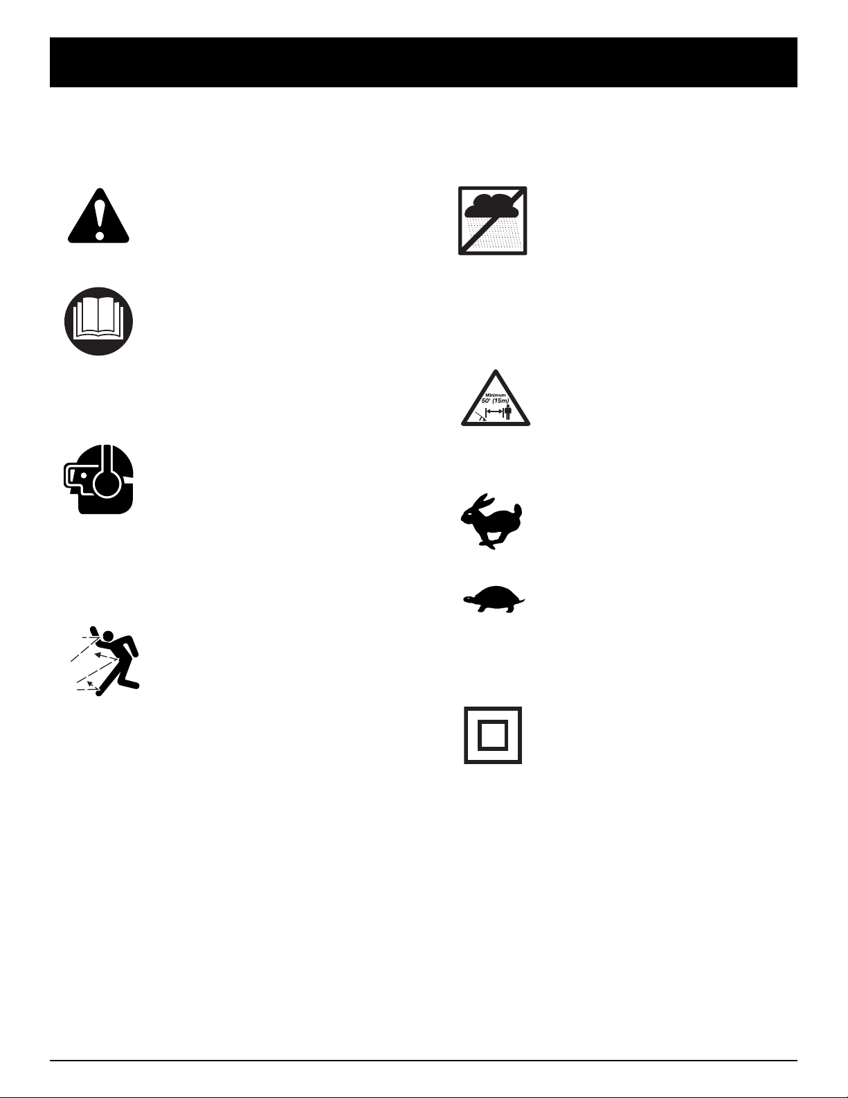
SYMBOL MEANING
The purpose of safety symbols is to attract your
attention to possible dangers. The safety symbols,
and their explanations, deserve your careful attention
and understanding. The safety warnings do not by
themselves eliminate any danger. The instructions or
warnings they give are not substitutes for proper
accident prevention measures.
NOTE: Advises you of information or instructions vital
to the operation or maintenance of the
equipment.
SYMBOL MEANING
READ ALL INSTRUCTIONS
BEFORE OPERATING
• Read the instructions carefully. Be familiar with the
controls and proper use of the unit.
• Do not operate this unit when tired, ill or under the
influence of alcohol, drugs or medication.
• Children and teens under the age of 15 must not use
the unit, except for teens guided by an adult.
• Inspect the unit before use. Replace damaged parts.
Make sure all fasteners are in place and secure.
Replace cutting attachment parts that are cracked,
chipped or damaged in any way. Make sure the cutting
attachment is properly installed and securely fastened.
Be sure that the cutting attachment shield is properly
attached, and positioned as recommended. Failure to
do so can result in personal injury to the operator and
bystanders, as well as damage to the unit.
• This unit was not designed to be used as a
brushcutter. Do not attach or operate this unit with any
type of brushcutting blade or brushcutting attachment.
• Use only a 0.080-inch (2.03 mm) diameter original
equipment manufacturer replacement line. Never use
metal-reinforced line, wire, chain or rope. These can
break off and become dangerous projectiles.
• Be aware of risk of injury to the head, hands and feet.
• Clear the area to be cut before each use. Remove
rocks, broken glass, nails, wire, string and other
objects which may be thrown or become entangled in
the cutting attachment. Clear the area of children,
bystanders and pets; keep them outside a 50-foot
(15 m.) radius, at a minimum. Even then, they are still
at risk from thrown objects. Encourage bystanders to
wear eye protection. If you are approached, stop the
unit immediately.
ELECTRICAL SAFETY WARNINGS
• Since the tool is double-insulated, a 2-wire extension
cord (an extension cord without a ground) may be
used. A 3-wire extension cord (an extension cord with
a ground) that uses a NEMA type connector (parallel
blade, U ground) is recommended. Extension cords
are available from your local retailer. Use only roundjacketed extension cords approved for outdoor use.
• This tool is double-insulated. Repair or replace damaged
cords.
RULES FOR SAFE OPERATION
When using the unit,
you must follow the
safety rules. Please read these instructions
before operating the unit in order to ensure
the safety of the operator and any bystanders.
Please keep these instructions for later use.
WARNING:
• IMPORTANT SAFETY INSTRUCTIONS •
Failure to obey a
safety warning can
result in injury to yourself and others.
Always follow the safety precautions to
reduce the risk of fire, electric shock and
personal injury.
WARNING:
Failure to obey a
safety warning will
result in serious injury to yourself or to
others. Always follow the safety precautions
to reduce the risk of fire, electric shock and
personal injury.
DANGER:
Failure to obey a
safety warning may
result in property damage or personal injury
to yourself or to others. Always follow the
safety precautions to reduce the risk of fire,
electric shock and personal injury.
CAUTION:
Indicates
danger,
warning or caution. Attention is required in
order to avoid serious personal injury. May
be used in conjunction with other symbols
or pictographs.
SAFETY ALERT:
When using electric
gardening appliances,
basic safety precautions should always be
followed to reduce the risk of fire, electric shock
and personal injury. Carefully read and
understand the entire operator's manual before
using your unit. Pay close attention to the
operating instructions and safety warnings.
DANGER:
To reduce the risk of
electrical shock, use
only SW-A, SOW-A, STW-A, STOW-A, SJW-A,
SJOW-A, SJTW-W or SJTOW-A cord types.
WARNING:

4
• To reduce the risk of electrical shock, this unit has a
polarized plug (one blade is wider than the other). This
unit will fit with a polarized plug in one way only. If the
plug does not fit fully into the unit, reverse the plug. If
it still does not fit, use a cord with the correct
connection. Do not modify the unit in any way.
*The wire size (AWG) for appliances using 12 to 16
amps is 14 AWG for 25 feet, 12 AWG for 50 feet, and
not recommended for 100 or 150 feet.
• CORD SETS: Make sure your cord set is in good
condition, with a cord that is heavy enough to carry
the current that your unit will draw. An undersized cord
set will cause a drop in line voltage resulting in a loss
of power, as well as overheating. The table shown
above illustrates the correct size to use depending on
the cord length and nameplate amperage rating. If in
doubt, use the next heavier size line gauge. The
smaller the gauge number, the heavier the cord. To
prevent the cord from disconnecting from the unit, use
the cord hook shown in the Operating Instructions.
• Ground Fault Circuit Interrupter (GFCI) protection
should be provided on the circuit(s) or outlet(s) that will
be used for the unit. Use receptacles with built-in
GFCI protection for an extra measure of safety.
• Do not abuse the power cord. Never carry the unit by
the cord or yank the cord to disconnect from receptacle.
Keep the cord from heat, oil and sharp edges.
• A nameplate on your unit indicates the voltage used.
Never connect the unit to an AC voltage that differs
from this voltage.
• Inspect all extension cords and the unit power connection
periodically. Look closely for deterioration, cuts or cracks
in the insulation. Also inspect the connections for damage.
Repair or replace the cords if any defects appear.
• Avoid dangerous environments. Never operate your unit
in damp or wet conditions. Moisture is a shock hazard.
• Do not use the unit in the rain.
• Do not handle the plug or the unit with wet hands.
WHILE OPERATING
• Wear safety glasses or goggles that are marked as
meeting ANSI Z87.1-1989 standards. Also wear
ear/hearing protection when operating this unit. Wear
a face or dust mask if the operation is dusty. Long
sleeve shirts are recommended.
• Wear heavy, long pants, boots and gloves. Do not
wear loose clothing, jewelry, short pants, sandals or
go barefoot. Secure hair above shoulder level.
• The cutting attachment shield must always be in place
while operating the unit. Do not operate unit without
both trimming lines extended, and the proper line
installed. Do not extend the trimming line beyond the
length of the shield.
• Adjust the D-handle to your size to provide the best
grip.
• Be sure the cutting attachment is not in contact with
anything before starting the unit.
• Use the unit only in daylight or good artificial light.
• Avoid accidental starting. Do not carry around a unit
that is plugged in with your finger on the trigger
switch. Be sure the switch is in the off position when
plugging in the unit.
• Use the right tool. Only use this tool for its intended
purpose.
• Do not overreach. Always keep proper footing and
balance.
• Always hold the unit with both hands when operating.
Keep a firm grip on both handles or grips.
• Keep hands, face, and feet at a distance from all
moving parts. Do not touch or try to stop the cutting
attachment when it rotates.
• Always stop the motor when cutting is delayed or
when walking from one cutting location to another.
• If you strike or become entangled with a foreign
object, stop the motor immediately and check for
damage. Do not operate before repairing damage. Do
not operate the unit with loose or damaged parts.
• Stop the unit and unplug it for maintenance or repair.
• Use only genuine original equipment manufacturer
replacement parts and accessories for this unit. These
are available from your authorized service dealer. Use
of any non-original parts or accessories could lead to
serious injury to the user, or damage to the unit, and
void your warranty.
• Keep unit clean of vegetation and other materials.
They may become lodged between the cutting
attachment and shield.
OTHER SAFETY WARNINGS
• Be sure to secure the unit while transporting.
• Store the unit in a dry area, locked up to prevent
unauthorized use or damage, and stored in a high
place out of the reach of children.
• Never douse or squirt the unit with water or any other
liquid. Keep handles dry, clean and free from debris.
Clean after each use. See the Cleaning and Storage
instructions.
• Keep these instructions. Refer to them often and use
them to instruct other users. If you loan someone this
unit, also loan them these instructions.
SAVE THESE INSTRUCTIONS
RULES FOR SAFE OPERATION
Cord length (ft.) 25 50 100 150
Wire size (AWG)* 16 16 16 14
MINIMUM WIRE SIZE FOR EXTENSION CORDS FOR
120 VOLT APPLIANCES USING 0-12 AMPS*
5
RULES FOR SAFE OPERATION
SYMBOL MEANING
• SAFETY ALERT SYMBOL
Indicates danger, warning, or
caution. May be used in conjunction
with other symbols or pictographs.
• WARNING - READ
OPERATOR'S MANUAL
Read the Operator’s Manual(s) and
follow all warnings and safety
instructions. Failure to do so can
result in serious injury to the
operator and/or bystanders.
• WEAR EYE AND HEARING
PROTECTION
WARNING:Thrown
objects and loud noise can cause
severe eye injury and hearing loss.
Wear eye protection meeting ANSI
Z87.1-1989 standards and ear
protection when operating this unit.
Use a full face shield when needed.
• THROWN OBJECTS AND
ROTATING CUTTER CAN
CAUSE SEVERE INJURY
WARNING:Keep clear
of blower outlet. Never point the
blower at yourself or others. Objects
can be thrown from blower. Do not
operate unit without proper
attachments and guards in place.
SAFETY AND INTERNATIONAL SYMBOLS
This operator's manual describes safety and international symbols and pictographs that may appear on this product.
Read the operator's manual for complete safety, assembly, operating and maintenance and repair information.
SYMBOL MEANING
• DO NOT USE IN THE RAIN
WARNING:Avoid
dangerous environments. Never
operate your unit in the rain, or in
damp or wet conditions. Moisture is
a shock hazard.
• KEEP BYSTANDERS AWAY
WARNING:Keep all
bystanders, especially children and
pets, at least 50 feet (15 m.) from the
operating area.
• THROTTLE CONTROL
Indicates “HIGH” or “FASTEST” speed.
• THROTTLE CONTROL
Indicates “IDLE”, “LOW” or
“SLOWEST” speed.
• DOUBLE INSULATED
Two systems of insulation are
provided instead of grounding.
There is no grounding provided
and no means of grounding should
be added to this unit.
6
RULES FOR SAFE OPERATION
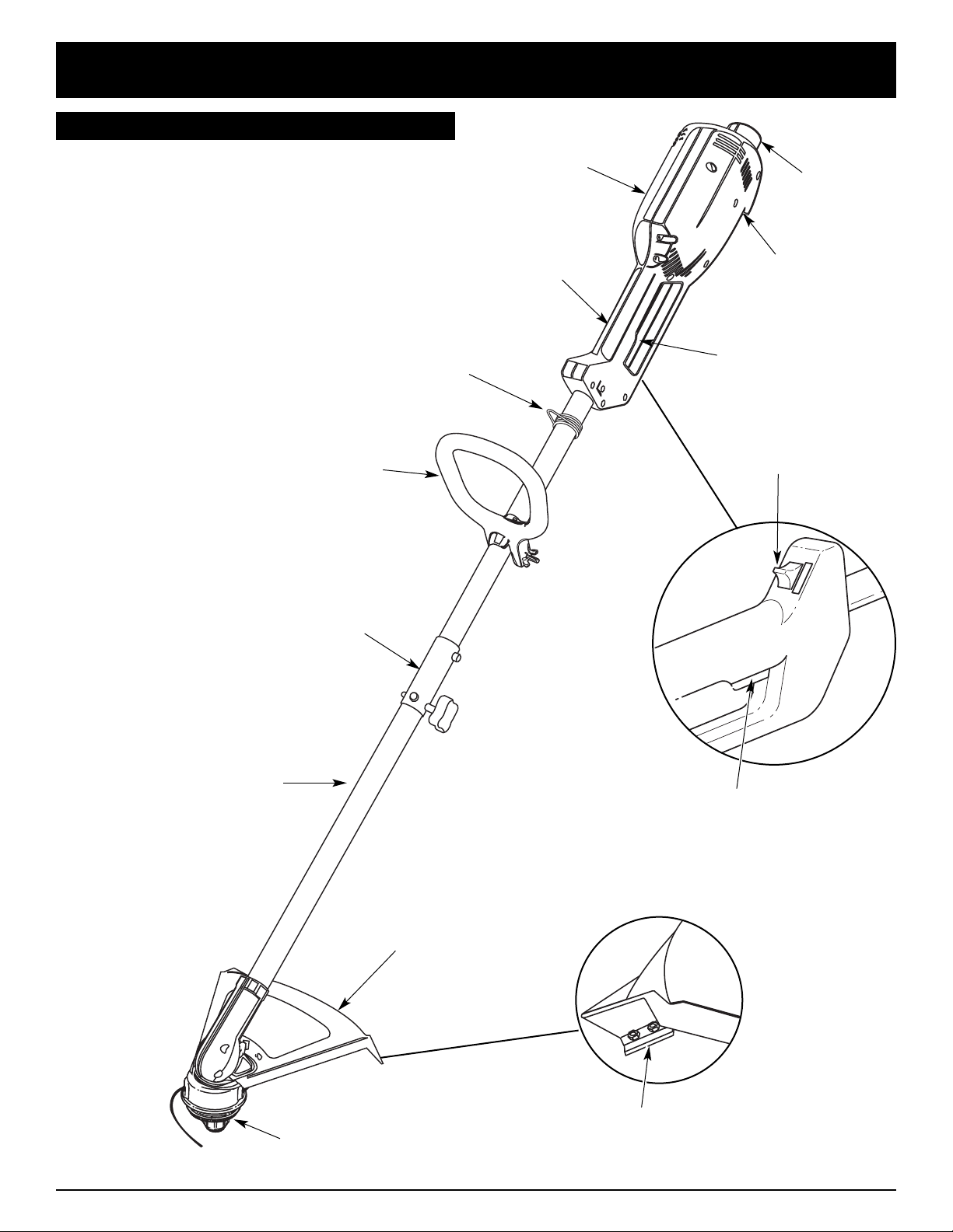
KNOW YOUR UNIT
As a trimmer:
• Cutting grass and light weeds
• Decorative trimming around trees, fences, etc.
Cutting Attachment
Shield
D-Handle
Cutting Attachment
Shaft Housing
Line Cutting Blade
Housing Grip
Switch Trigger
Recessed
Plug
Motor Housing
Switch Trigger
Two-Speed
Switch
EZ-Link™
Cord Hook
Shoulder
Harness

7
ASSEMBLY INSTRUCTIONS
INSTALL THE CUTTING ATTACHMENT SHIELD
Use the following instructions if the cutting attachment
shield on your unit is not installed or if you ever need to
re-install it.
1. Slide the cutting attachment shield into the shield
mount on the cutting attachment. Align the screw
holes in the shield with the holes in the cutting
attachment (Fig. 3).
Fig. 3
Fig. 5
Fig. 4
Cutting Attachment
Shield
Screws
Shaft Housing
Hex Lock Nut
Cutting Attachment
Shield
Cutting Attachment
2. Place a hex lock nut into one of the three recessed
holes on the top of the cutting attachment shield (Fig 4).
3. Install a screw into the hole from the bottom of the
cutting attachment shield and screw it into the nut
installed in step 2 (Fig 5). Do not tighten.
4. Repeat steps 2 and 3 until all three screws have
been started, then tighten securely.
Recessed Holes
Shield Mount
Never operate the
trimmer without the
cutting attachment shield in place to
prevent serious personal injury.
WARNING:
On some units, the D-handle may be pre-installed. In this
case you must loosen screws and adjust the handle to fit
the operator. Go to step 4 if the D-handle is pre-installed.
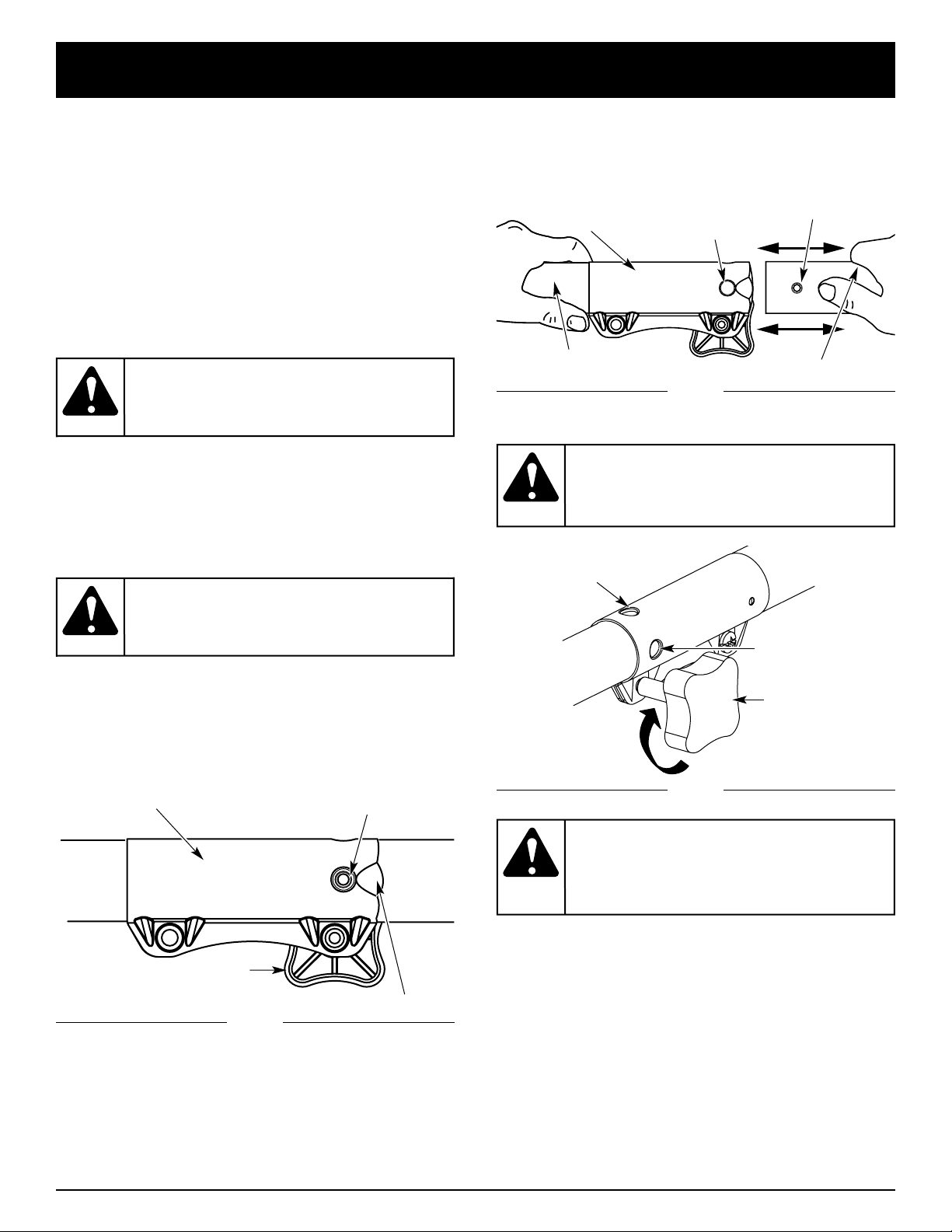
INSTALL AND ADJUST THE D-HANDLE
1. Remove the items that were installed on the D-handle
for shipping.
2. Place the D-handle over the shaft housing and push
it on the boom (Fig. 1).
3, Install the bolt, washer and wing nut. Tighten them.
4. If the D-handle was pre-installed, loosen the wing nut
on it just enough so it is movable.
5. While holding the unit in the operating position,
arrange or rotate the D-handle to the location that
provides you the best grip (Fig. 2).
6. Tighten the wing nut until the D-handle is secure.
Fig. 1
Fig. 2
8
OPERATING INSTRUCTIONS
For decorative trimming/edging with the line head cutting
attachment, lock the release button of the cutting
attachment into the 90° hole or the 180° hole (Fig. 8).
For edging with the edger add-on, lock the release
button of the cutting attachment only into the 180°
trimming hole/ primary hole (Fig. 8).
OPERATING THE EZ-LINK™ SYSTEM
The EZ-Link™ system enables the use of these optional
Add-Ons:
Blower/Vacuum . . . . . . . . . . . . . . . . . . . . . . . . . . BV720r
Cultivator . . . . . . . . . . . . . . . . . . . . . . . . . . . . . . GC720r
Edger . . . . . . . . . . . . . . . . . . . . . . . . . . . . . . . . . . LE720r
Snow Thrower . . . . . . . . . . . . . . . . . . . . . . . . . . . ST720r
Straight Shaft Trimmer . . . . . . . . . . . . . . . . . . . . SS725r
Tree Pruner . . . . . . . . . . . . . . . . . . . . . . . . . . . . . TP720r
Turbo Blower . . . . . . . . . . . . . . . . . . . . . . . . . . . . TB720r
Removing the Cutting Attachment or Add-Ons
1. Turn the knob counterclockwise to loosen (Fig. 6).
2. Press and hold the release button (Fig. 6).
3. While firmly holding the upper shaft housing, pull
the cutting attachment or add-on straight out of the
EZ-Link™ coupler (Fig. 7).
Installing the Cutting Attachment or Add-Ons
NOTE: To make installing or removing the add-on
easier, place the unit on the ground or on a work
bench.
1. Turn knob counterclockwise to loosen (Fig. 6).
Fig. 6
EZ-Link™ Coupler
Release Button
Guide Recess
Knob
Primary Hole
Upper Shaft Housing
90˚ Edge
Trimming Hole
EZ-Link™ Coupler
2. While firmly holding the add-on, push it straight into
the EZ-Link™ coupler (Fig. 7).
NOTE: Aligning the release button with the guide recess
will help installation (Fig. 6).
3. Turn the knob clockwise to tighten (Fig. 8).
Fig. 7
Fig. 8
Knob
180˚ Trimming Hole/
Primary Hole
Lower Shaft Housing
Release Button
Prior to operation,
read and understand
the operator’s manual for unit to be used with
this add-on.
WARNING:
To avoid serious
personal injury and
damage to the unit, shut the unit off before
removing or installing add-ons.
WARNING:
The add-ons with the
coupler system is to
be used in the primary hole only. Using the
wrong hole could lead to personal injury or
damage to the unit.
CAUTION:
Lock the release
button in the primary
hole (Fig. 10) and securely tighten the knob
before operating this unit.
CAUTION:

9
OPERATING INSTRUCTIONS
Always wear eye,
hearing, foot and
body protection to reduce the risk of injury
when operating this unit.
WARNING:
CONNECTING THE CORD
Use the cord hook when connecting the extension cord to
the power cord outlet. This helps prevent any
disconnection.
1. Make a narrow loop with the extension cord.
2. Push the loop through the opening and move it onto
the hook on the motor housing (Fig. 9).
3. Plug the cord properly into the socket.
Only use outdoor-approved extension cords. Cord sets
are specified in the Important Safety Information section.
STARTING/STOPPING INSTRUCTIONS
Once the unit is plugged in, stand in the operating
position (Fig. 11). Squeeze the trigger to start the unit. To
stop the unit, release the trigger (Fig. 10).
Trigger
HOLDING THE TRIMMER
Before operating the unit, stand in the operating position
(Fig. 11). Check for the following:
• The operator is wearing eye protection and proper
clothing
• With a slightly-bent right arm, the operator’s hand is
holding the shaft grip
• The operator’s left arm is straight, the left hand
holding the D-handle
• The unit is at waist level
•
The cutting attachment is parallel to the ground and
easily contacts the grass without the need to bend ove
r
• The extension cord is safely behind the operator
Fig. 11
ADJUSTING TRIMMING LINE LENGTH
The Bump Head™ cutting attachment allows you to
release trimming line without stopping the motor. To
release more line, lightly tap the cutting attachment on the
ground (Fig. 12) while operating the trimmer at high speed.
NOTE: Always keep the trimming line fully extended.
Line release becomes more difficult when the
cutting line gets shorter.
Always wear eye,
hearing, foot and
body protection to reduce the risk of injury
when operating this unit.
WARNING:
Fig. 9
TWO-SPEED SWITCH
This unit is equipped with a two-speed switch: a
powerful high speed for demanding yard work, and a
precision low speed for light-duty yard work.
Push the switch up for high speed trimming. Push the
switch down for low speed trimming (Fig. 10).
Fig. 10

10
OPERATING INSTRUCTIONS
TIPS FOR BEST TRIMMING RESULTS
• Keep the cutting attachment parallel to the ground.
• Do not force the cutting attachment. Allow the tip of
the line to do the cutting, especially along walls.
Cutting with more than the tip will reduce cutting
efficiency and may overload the motor.
• Cut grass over 8 inches (200 mm) by working from
top to bottom in small increments to avoid
premature line wear or motor drag.
Fig. 12
Each time the head is bumped, about 1 inch (25.4 mm)
of trimming line releases. A blade in the cutting
attachment shield will cut the line to the proper length if
any excess line is released.
For best results, tap the bump knob on bare ground or
hard soil. If you attempt a line release in tall grass, the
motor may stall. Always keep the trimming line fully
extended. Line release becomes more difficult when the
cutting line gets shorter.
NOTE: Do not rest the Bump Head™ on the ground
while the unit is running.
Some line breakage will occur from:
• Entanglement with foreign matter
• Normal line fatigue
• Attempting to cut thick, stalky weeds
• Forcing the line into objects such as walls or fence
posts
Do not remove or alter
the line cutting blade
assembly. Excessive line length will make the
clutch overheat. This may lead to serious
personal injury or damage to the unit.
CAUTION:
DECORATIVE TRIMMING
Decorative trimming is accomplished by removing all
vegetation around trees, posts, fences and more.
Rotate the whole unit so that the cutting attachment is at
a 30° angle to the ground (Fig. 13).
Fig. 13
• Cut from right to left whenever possible. Cutting to
the left improves the unit's cutting efficiency.
Clippings are thrown away from the operator.
• Slowly move the trimmer into and out of the cutting
area at the desired height. Move either in a forwardbackward or side-to-side motion. Cutting shorter
lengths produces the best results.
• Trim only when grass and weeds are dry.
• The life of your cutting line is dependent upon:
• Following the trimming techniques
• What vegetation is being cut
• Where vegetation is cut
For example, the line will wear faster when trimming
against a foundation wall as opposed to trimming
around a tree.

11
MAINTENANCE AND REPAIR INSTRUCTIONS
SERVICING DOUBLE INSULATED UNITS
This unit is double-insulated. In a double-insulated unit,
two systems of insulation are provided instead of
grounding. There is no grounding provided and no
means of grounding should be added to this unit.
Extreme care and knowledge of the system is required
when servicing a double-insulated unit. Service should
be performed by qualified service personnel only.
Replacement parts for a double-insulated unit must be
identical to the parts they replace. Refer any repair to an
authorized service dealer. A double-insulated unit is
marked with the words “double insulation” or “double
insulated.”
LINE INSTALLATION FOR THE SPEEDSPOOL
®
Always use original equipment manufacturer 0.080 inch
(2.03 mm) replacement line. Line other than the specified
may make the motor overheat or fail.
There are two methods to replace the SpeedSpool
®
trimming line:
• Wind the inner reel with new line
• Install a pre-wound inner reel
Winding the Inner Reel With New Line
NOTE: It Is unnecessary to remove the bump knob to
install a new trimming line.
1. Cut two pieces of 0.080 inch (2.03 mm) trimming
line, 10 feet (3 m) long.
2. Hold the outer spool and turn the inner reel
counterclockwise to line up the arrows on the outer
spool and inner reel (Fig. 14).
Top View Of The SpeedSpool
®
Outer Spool
Inner Reel
Fig. 14
Bump Knob
Arrows
Never use metal-
reinforced line, wire,
chain or rope. These can break off and
become dangerous projectiles.
WARNING:
Always use the
correct line length
when installing trimming line on the unit.
The line may not release properly if the line
is too long.
WARNING:
Trimming Line
Line Loading Hole
Eyelet
5. Insert the line into the locking hole. Do not push the
line more than a 1/2 inch (12.7 mm) into the line
locking hole. The line will form a small loop (Fig. 16)
when it is inserted correctly.
3. Pull old line out of the line loading and line locking
holes (Fig. 14 and 15).
4. Insert a piece of trimming line straight into one of the
two eyelets in the outer spool. Push it up through the
line loading hole in the inner reel (Fig. 15). Do not
bend the line when inserting it into the eyelet.
Fig. 15

12
6. Pull the line from the outer spool until the line is tight
against the inner reel (Fig. 17).
Fig. 17
INSTALLING A PRE-WOUND REEL
1. Turn the bump knob counterclockwise and remove
the bump knob, spring and foam seal (Fig. 20).
9. If winding the line becomes difficult or if the line
jams, pull the ends of the line from the spool
(Fig. 19). Continue winding the inner reel
counterclockwise.
Fig. 18
Fig. 19
7. Repeat procedures 4-6 with the second piece of line.
8. Hold the outer spool. Wind the inner reel
counterclockwise until approximately four (4) inches
(102 mm) of line remain (Fig. 18).
NOTE: Do not wind the inner reel before installing the
second piece of line.
Bump Knob
Foam Seal
Spring
Inner Reel
Fig. 20
2. Pull the old inner reel with existing line from the outer
spool.
3. Insert the ends of the prewound inner reel line into
the outer spool eyelets (Fig. 21). Push the new inner
reel, arrow side up, into the outer spool.
Fig. 21
Line Locking Hole
Fig. 16
4. Hold the inner reel in place and install the bump
knob, spring and foam seal. Press down and turn the
bump knob clockwise. Grasp the ends and pull firmly
to release the line from the holding slots in the inner
reel (Fig. 19).
MAINTENANCE AND REPAIR INSTRUCTIONS

13
SPEEDSPOOL REPLACEMENT PARTS
Replacement Line . . . . . . . . . . . . . . . . . . . . . . . . 181472
Replacement Line Cartridge . . . . . . . . . . . . . . . . 181460
Inner Reel Spring . . . . . . . . . . . . . . . . . . . . . . . . 181465
Foam Seal . . . . . . . . . . . . . . . . . . . . . . . . . . . . . . 181467
Inner Reel . . . . . . . . . . . . . . . . . . . . . . . . . . . . . . 181464
Bump Knob Assembly . . . . . . . . . . . . . . . . . . . . 181468
These SpeedSpool®replacement parts can be
purchased from your local authorized dealer.
Releasing the Inner Reel
If the SpeedSpool®does not release line correctly, pull
the ends of the line firmly from the spool (Fig. 19). If this
does not the release line, follow the Cleaning the
SpeedSpool®instructions.
4. Remove any existing line from the inner reel before
cleaning. Remove any debris or grass from the knob,
spring, inner reel and foam seal. Wash the inner reel
with warm soapy water (Fig. 23).
Fig. 22
CLEANING THE SPEEDSPOOL
®
Cleaning the SpeedSpool®may be necessary if:
• A jammed or excessive line must be removed
• The SpeedSpool®becomes difficult to wind or does
not operate correctly when bumping the head on the
ground
1. Hold the outer spool, and unscrew the bump knob
counterclockwise (Fig. 22).
2. Pull out the bump knob, spring and foam seal (Fig. 20).
Shaft
Plunger
7. Place the bump knob, spring and foam seal into the
inner reel (Fig. 20).
8. Press the bump knob down and tighten clockwise.
9. Install new line as described in Line Installation for
the SpeedSpool
®
.
5. Clean the shaft and the inner surface of the outer
spool. To clean the shaft underneath the plunger,
press down on the plunger (Fig. 24). Remove any dirt
or debris from the shaft.
NOTE: The inner reel must be totally dry before
reinstalling it into the outer spool. Do not lubricate
the inner reel or outer spool assembly.
6. Place the inner reel into the outer spool.
Fig. 24
Inner Reel
Fig. 23
3. Pull the inner reel with existing line from the outer
spool (Fig. 21).
CLEANING THE UNIT
Switch off the unit and disconnect it from the power
source. Use a small brush to clean off the outside of the
unit. Do not use strong detergents. Household cleaners
that contain aromatic oils such as pine and lemon, and
solvents such as kerosene, can damage plastic housing
or handle. Wipe off any moisture with a soft cloth. Also
keep the air vents free of obstructions.
STORAGE
• Store the unit locked up to prevent unauthorized use
or damage.
• Store the unit in a dry, well-ventilated area.
• Store the unit out of the reach of children.
INSPECT EXTENSION CORDS
Inspect all extension cords periodically. Look closely for
deterioration, cuts or cracks in the insulation. Inspect the
connectors for damage. Replace cords if defective or
damaged.
To avoid serious
personal injury,
always turn your unit off and unplug it
before you clean or service it.
WARNING:
MAINTENANCE AND REPAIR INSTRUCTIONS

14
TROUBLESHOOTING
If further assistance is required, contact your authorized service dealer.
CAUSE ACTION
Cutting attachment bound with grass Stop the motor and clean cutting attachment
Cutting attachment out of line Refill with new line
Inner reel bound up Replace the inner reel
Cutting head dirty Clean inner reel and outer spool
Line welded Disassemble, remove the welded section and rewind
Line twisted when refilled Disassemble and rewind the line
Not enough line is exposed Push the bump knob and pull out line until 4 inches
(102 mm) of line is outside of the cutting attachment
CAUSE ACTION
Unit is unplugged Check cord to make sure it is still plugged into an
electrical outlet
MOTOR WILL NOT START
CUTTING ATTACHMENT WILL NOT ADVANCE LINE
CAUSE ACTION
Oil, cleaner or lubricant in cutting head Clean and thoroughly dry the cutting head
CUTTING LINE ADVANCES UNCONTROLLABLY

15
SPECIFICATIONS
Motor type..........................................................................................................................................A.C.,120 Volts Electric
Operating RPM............................................................................................................................................ up to 7,800 rpm
Ignition Switch ........................................................................................................................................................... Trigger
Amperage............................................................................................................................................................... 5.5 amps
MOTOR
DRIVE SHAFT and CUTTING ATTACHMENT
Drive Shaft Housing....................................................................................................................................... Steel (EZ-Link)
Shoulder Strap ........................................................................................................................................................ Optional
Approximate Unit Weight (cutting attachment shield and D-handle)..................................................................9 lbs. (4 kg)
Cutting Mechanism................................................................................................ SpeedSpool®Dual String Cutting Head
Line Spool............................................................................................................................................. Bump Line Releaser
Line Spool Diameter .......................................................................................................................3 inches (76.2 mm)
Cutting Path Diameter................................................................................................................................... 15 in (381 mm)
Trimming Line Diameter .......................................................................................................................... 0.080 in (2.03 mm)

16
NOTES

17
NOTES

MANUFACTURER’S LIMITED WARRANTY FOR:
No implied warranty, including any implied warranty of
merchantability or fitness for a particular purpose,
applies after the applicable period of express written
warranty above as to the parts as identified. No other
express warranty or guaranty, whether written or oral,
except as mentioned above, given by any person or
entity, including a dealer or retailer, with respect to any
product shall bind MTD. During the period of the
Warranty, the exclusive remedy is repair or replacement
of the product as set forth above. (Some states do not
allow limitations on how long an implied warranty lasts, so
the above limitation may not apply to you.)
The provisions as set forth in this Warranty provide the
sole and exclusive remedy arising from the sales. MTD
shall not be liable for incidental or consequential loss or
damages including, without limitation, expenses incurred
for substitute or replacement lawn care services, for
transportation or for related expenses, or for rental
expenses to temporarily replace a warranted product.
(Some states do not allow limitations on how long an implied
warranty lasts, so the above limitation may not apply to you.)
In no event shall recovery of any kind be greater than the
amount of the purchase price of the product sold. Alteration
of the safety features of the product shall void this Warranty.
You assume the risk and liability for loss, damage, or injury
to you and your property and/or to others and their property
arising out of the use or misuse or inability to use the
product.
This limited warranty shall not extend to anyone other than
the original purchaser, original lessee or the person for whom
it was purchased as a gift.
How State Law Relates to this Warranty: This warranty
gives you specific legal rights, and you may also have other
rights which vary from state to state.
To locate your nearest service dealer dial 1-800-345-8746
in the United States or 1-800-668-1238 in Canada.
MTD LLC
P.O. Box 361131
Cleveland, OH 44136-0019
The limited warranty set forth below is given by MTD
LLC (“MTD”) with respect to new merchandise purchased and
used in the United States, its possessions and territories.
MTD warrants this product against defects in material and
workmanship for a period of two (2) years commencing on the
date of original purchase and will, at its option, repair or
replace, free of charge, any part found to be defective in
material or workmanship. This limited warranty shall only apply
if this product has been operated and maintained in
accordance with the Operator’s Manual furnished with the
product, and has not been subject to misuse, abuse,
commercial use, neglect, accident, improper maintenance,
alteration, vandalism, theft, fire, water or damage because of
other peril or natural disaster. Damage resulting from the
installation or use of any accessory or attachment not
approved by MTD for use with the product(s) covered by this
manual will void your warranty as to any resulting damage. This
warranty is limited to ninety (90) days from the date of original
retail purchase for any MTD product that is used for rental or
commercial purposes, or any other income-producing purpose.
HOW TO OBTAIN SERVICE: Warranty service is available,
WITH PROOF OF PURCHASE THROUGH YOUR LOCAL
AUTHORIZED SERVICE DEALER. To locate the dealer in your
area, please check for a listing in the Yellow Pages or contact
the Customer Service Department of MTD LLC by calling
1-800-345-8746 or writing to P.O. Box 361131, Cleveland OH
44136-0019 or if in Canada call 1-800-668-1238. No product
returned directly to the factory will be accepted unless prior
written permission has been extended by the Customer
Service Department of MTD LLC.
This limited warranty does not provide coverage in the
following cases:
A. Tune-ups - Spark Plugs, Carburetor Adjustments, Filters.
B. Wear items - Bump Knobs, Outer Spools, Cutting Line,
Inner Reels, Starter Pulley, Starter Ropes, Drive Belts.
C. MTD does not extend any warranty for products sold or
exported outside of the United States of America, its
possessions and territories, except those sold through
MTD’s authorized channels of export distribution.
MTD reserves the right to change or improve the design of
any MTD Product without assuming any obligation to modify
any product previously manufactured.

Manuel de l'utilisateur
Français
PARTIE NUMÉRO. 769-00936 (1/04)
Désherbeuse
Electrique
Model
YM137
MANUEL IMPORTANT À NE PAS JETER

F2
Copiez le numéro
de série ici :
Copiez le numéro de
modèle / pièce mère ici :
TOUS NOS REMERCIEMENTS
Nous vous remercions d'avoir acheté ce produit de
qualité. Cet outil mécanique de plein air moderne est
conçu pour vous rendre service pendant longtemps. Il
vous sauvera beaucoup de temps comme vous pourrez
vous en rendre compte. Ce manuel de l'utilisateur
comporte un mode d'emploi facile à comprendre. Prenez
soin de lire le manuel au complet et suivez toutes ses
instructions à la lettre afin de conserver votre nouvel outil
mécanique de plein air en excellent état de
fonctionnement.
RÉFÉRENCES, ILLUSTRATIONS ET
SPÉCIFICATIONS RELATIVES AU PRODUIT
Toutes les informations, illustrations et spécifications
contenues dans ce manuel tiennent compte des
dernières informations techniques disponibles au
moment de mettre sous presse. Nous nous réservons le
droit d'y apporter des modifications à tout moment, sans
préavis.
Copyright© 2003 MTD SOUTHWEST INC., Tous droits
réservés.
NFORMATIONS D’ENTRETIEN
Tout entretien effectué sur cet appareil pendant et après
la période de garantie doit être fait par un concessionnaire agréé uniquement. Obtenez la liste des
concessionnaires agréés appelez le 1-800-345-8746, ou
le 1-800-668-1238 au Canada. Pour de plus amples
informations à propos de votre appareil, visitez
www.yardman.com.
NE RETOURNEZ PAS L'APPAREIL AU DÉTAILLANT
CHEZ QUI VOUS L'AVEZ ACHETÉ. TOUT SERVICE
SOUS GARANTIE NÉCESSITE UNE PREUVE D'ACHAT.
Avant d'assembler votre nouvel équipement, repérez la
plaque signalétique de l'appareil et copiez ses
informations dans l'espace ci-dessous. Ces informations
sont essentielles si vous désirez obtenir de l'aide auprès
de notre service technique ou d'un distributeur agréé. Un
exemple de plaque signalétique est présenté ci-dessous.
Prenez soin de lire et de bien comprendre ce manuel avant de démarrer ou de faire fonctionner cet équipement.
CE PRODUIT EST COUVERT PAR UN OU PLUSIEURS BREVETS AMÉRICAINS, ET D’AUTRES SONT EN INSTANCE.
TABLE DES MATIÈRES
Service technique . . . . . . . . . . . . . . . . . . . . . . . . . . .2
Consignes de sécurité . . . . . . . . . . . . . . . . . . . . . . .3
Familiarisez-vous avec votre appareil . . . . . . . . . . .6
Instructions de montage . . . . . . . . . . . . . . . . . . . . . .7
Mode d'emploi . . . . . . . . . . . . . . . . . . . . . . . . . . . . .8
Entretien et réparations . . . . . . . . . . . . . . . . . . . . .11
Tableau de dépannage . . . . . . . . . . . . . . . . . . . . . .14
Caractéristiques . . . . . . . . . . . . . . . . . . . . . . . . . . .15
Garantie . . . . . . . . . . . . . . . . . . . . . . . . . . . . . . . . .18
Liste des pièces . . . .Intérieure de la Couverture Arrière
Numéro de modèle
Numéro de série
Numéro de pièce mère
INTRODUCTION
Si vous éprouvez des difficultés à assembler ce produit
ou si vous avez des questions concernant les
commandes, le fonctionnement ou l’entretien de cet
appareil, veuillez communiquer avec notre service
technique.
MODEL :
S/N :
ITEM :

F3
CONSIGNES DE SÉCURITÉ
SYMBOLE SIGNIFICATION
SYMBOLE SIGNIFICATION
LIRE TOUTES LES INSTRUCTIONS
AVANT UTILISATION
• Lire les instructions attentivement. Se familiariser avec
les commandes et l’utilisation correcte de cet outil.
• Ne pas utiliser l’outil si vous êtes fatigué, malade ou
sous l’effet de l’alcool, de drogues ou de médicaments.
• Inspectez l'appareil avant utilisation. Remplacez les
pièces endommagées.. Assurez-vous que les fixations
sont solidement en place. Remplacez les pièces de
l'accessoire de coupe qui sont fendillées, ébréchées
ou endommagées. Assurez-vous que l'accessoire de
coupe est correctement installé et solidement fixé.
Assurez-vous que le protecteur d'accessoire de coupe
est correctement fixé et positionné comme
recommandé. Vous risquez sinon de causer des
blessures à l'opérateur et aux spectateurs, et
d'endommager l'appareil.
• N'utilisez que du fil de remplacement d’origine du
fabrican de 2,03 mm (0,080 po) de diamètre. N'utilisez
jamais de fil, de chaîne ou de cordon à renfort
métallique car ils peuvent se briser et se transformer
en projectile dangereux.
• Soyez conscient des risques de blessure à la tête, aux
mains et aux pieds.
• Dégagez la zone de coupe avant chaque usage.
Enlevez tous les objets pouvant être projetés ou
happés par l'accessoire de coupe : cailloux, verre
brisé, clous, fil ou ficelle. Éloignez enfants, spectateurs
et animaux de la zone de coupe. Tenez-les à au moins
15 m (50 pi) de là mais sachez que les spectateurs
risquent quand même d'être atteints par des objets
projetés. Les spectateurs doivent porter des
protections oculaires. Arrêtez immédiatement le
moteur et l'accessoire de coupe si quelqu'un
s'approche de vous.
• Cet appareil n'est pas conçu pour servir de
débroussailleuse. N'utilisez cet appareil avec aucun
type de lame ou d'accessoire de débroussaillage.
AVERTISSEMENTS DE SÉCURITÉ ÉLECTRIQUE
• Comme cet outil comporte une isolation double, il est
donc possible d’utiliser des rallonges à 2 conducteurs
(rallonges sans terre). Cependant, il est tout à fait possible
d’utiliser des rallonges à 3 conducteurs (rallonges avec fil
de terre), qui comportent des fiches de type NEMA (fiches
parallèles, fiche terre en forme de U). Ces rallonges sont
disponibles auprès de votre revendeur local. Veillez à
n’utiliser que des rallonges à section circulaire,
approuvées pour une utilisation extérieure.
• Cet outil comporte une isolation double. Pour toutes
les réparations, utilisez uniquement des pièces de
rechange identiques. Tout cordon électrique
endommagé doit être réparé ou remplacé.
• IMPORTANTES CONSIGNES DE SÉCURITÉ •
Les symboles de sécurité attirent votre attention sur
des dangers potentiels. Ces symboles et leurs détails
explicatifs méritent que vous les lisiez et compreniez
bien. Les avertissements de sécurité ne peuvent éviter
les dangers de par eux-mêmes. Les consignes ou
mises en garde qu'ils donnent ne remplacent pas des
mesures préventives appropriées contre les accidents.
REMARQUE: donne des informations ou des
instructions vitales pour le fonctionnement ou
l'entretien de l'équipement.
le non-
respect d’un
avertissement peut causer dommages matériels
ou blessures graves pour tous. Respectez les
consignes de sécurité afin de réduire les risques
d'incendie, d'électrocution et de blessures.
AVERTISSEMENT:
le non-respect d’un
avertissement peut
causer dommages matériels ou blessures
graves pour tous. Respectez les consignes de
sécurité afin de réduire les risques d'incendie,
d'électrocution et de blessures.
DANGER:
le non-
respect
d’un avertissement peut causer dommages
matériels ou blessures graves pour tous.
Respectez toujours les consignes de sécurité
afin de réduire les risques d'incendie,
d'électrocution et de blessures.
MISE EN GARDE:
indique un danger, un avertissement ou une
mise en garde. Soyez vigilant afin d'éviter toute
blessure grave. Ce symbole peut être combiné
à d'autres symboles ou pictogrammes.
ALERTE DE SÉCURITÉ:
respectez toujours les
consignes de sécurité
durant l’utilisation d’appareils de jardinage
électriques afin de réduire les risques
d’incendie, d’électrocution et de blessures.
Prenez soin de bien lire et comprendre tout le
manuel de l’utilisateur avant d’utiliser la
souffleuse/aspirateur. Faites particulièrement
attention au mode d'emploi et aux
avertissements de sécurité.
DANGER:
Pour
réduire le
risque de choc électrique, utilisez uniquement
des rallonges électriques approuvées pour une
utilisation extérieure., comme par exemple les
rallonges à cordons de type SW-A, SOW-A, STWA, STOW-A, SJW-A, SJOW-A, SJTW-W ou SJTOW.
AVERTISSEMENT:

F4
CONSIGNES DE SÉCURITÉ
• Pour réduire le risque de choc électrique, cet appareil est
pourvu d’une fiche polarisée (une lame est plus large que
l’autre). Cet appareil ne peut être inséré dans une prise
polarisée que d’une seule manière. S’il n’est pas possible
d’insérer entièrement la fiche dans la prise, essayez de
brancher la fiche dans l’autre sens. Si malgré tout, il n’est
pas possible d’insérer la fiche, remplacez le cordon par un
cordon qui comporte les bonnes fiches. Ne modifiez cet
appareil en aucun cas.
*La grosseur du fil (AWG) pour l’ampérage de 12 à 19
ampères est de 14 AWG pour 25 pieds, de 12 AWG pour
50 pieds et n’est pas recommandé pour 100 ou 150 pieds.
• JEUX DE CORDONS: Vérifiez que votre jeu de cordons est
en bon état de fonctionnement. Si vous utilisez un jeu de
cordons, assurez vous de bien utiliser un cordon de calibre
suffisant pour laisser passer le courant de charge de votre
appareil. Un jeu de cordons à section trop faible risque de
provoquer des chutes de tension de ligne, qui entraînent une
perte de puissance et une surchauffe. Le tableau ci-dessous
donne les calibres corrects à utiliser, en fonction de la
longueur du cordon et de la valeur de l’intensité nominale.
En cas de doute, utilisez la section de câble immédiate-ment
supérieure. Un numéro de calibre faible correspond à une
forte section de câble. Référez vous à la Mode D’emploi
pour réduire le risque de débranchement du cordon de
l’appareil pendant le fonctionnement, du jeu de cordons.
• Le(s) circuit(s) électrique(s) ou la(les) prise(s)
d’alimentation de cet outil de jardinage doit(doivent)
comporter une protection de type GFCI (qui coupe le
circuit en cas de défaut de terre). Il existe des prises qui
comportent une protection GFCI, et que l’on peut utiliser
dans ce cas de figure.
• Votre appareil est pourvu d’une plaquette du
constructeur, qui indique le type de tension à utiliser.
N’alimentez jamais cet appareil avec une tension
alternative différente de celle affichée.
• Ne maltraitez pas le cordon. Ne tirez jamais l’appareil par
le cordon et ne le débranchez pas en tirant sur le cordon.
Protégez celui-ci de la chaleur, de l’huile et des bords
tranchants.
• Procédez à une inspection périodique de vos rallonges
électriques et de la fiche de raccord de votre appareil.
Examinez plus particulièrement l’isolation qui ne doit pas
présenter de traces de détérioration, de coupures ou de
mise à nu. Inspectez également les raccords qui doivent être
en bon état. Si les cordons paraissent endommagés,
remplacez les ou réparez les.
• Evitez d’utiliser cet appareil dans des conditions
dangereuses. Ne le faites jamais fonctionner en
atmosphère humide ou mouillée. L’humidité constitue un
danger réel de choc électrique.
• N’utilisez pas cet appareil sous la pluie.
• Ne touchez pas la fiche ou l’appareil lui même si vos
mains sont mouillées.
PENDANT L’UTILISATION
• Portez des lunettes de sécurité conformes aux normes
ANSI Z87.1 ainsi que des protège-oreilles durant
l'utilisation de l'appareil. Portez un masque facial ou
antipoussières si vous travaillez dans un lieu poussiéreux.
• Ajustez la poignée en D selon votre taille pour mieux
l'agripper.
• N'utilisez l'appareil qu'en plein jour ou avec un bon
éclairage artificiel.
• Portez des pantalons épais et longs, des bottes, des
gants et une chemise à manches longues. Ne marchez
pas pieds nus et évitez les vêtements lâches, bijoux,
pantalons courts et sandales. Relevez les cheveux audessus des épaules.
• Le protecteur d'accessoire de coupe doit toujours être en
place lors de l'utilisation de l'appareil. Ne faites pas marcher
l'appareil sans que les deux fils soient bien déployés, en
supposant qu'un fil approprié a été installé. Assurez-vous que
le fil ne dépasse pas le protecteur de sécurité.
• Évitez tout démarrage accidentel. Ne transportez pas
l'appareil branché, le doigt sur l’interrupteur. Mettez ce
dernier hors tension avant de brancher.
• Ne vous étirez pas. Tenez-vous toujours bien sur vos
pieds en position d'équilibre.
• Tenez toujours l'appareil des deux mains lorsque vous le
faites marcher. Agrippez fermement les poignées avant et
arrière.
• Gardez les mains, le visage et les pieds éloignés des
pièces mobiles. Ne touchez pas et n'essayez pas
d'arrêter l'accessoire de coupe en rotation.
• Servez-vous des outils appropriés. N'utilisez cet outil que
pour son usage prévu.
• Ne faites pas fonctionner le moteur à un régime plus
élevé que nécessaire pour couper, tailler ou faire les
bordures. Ne faites pas tourner le moteur à haut régime si
vous ne vous faites pas de coupe.
• Arrêtez toujours le moteur lorsque vous suspendez la
coupe ou lorsque vous vous déplacez d'un lieu de travail
vers un autre.
• Si vous heurtez un corps étranger ou que celui-ci est
happé, arrêtez le moteur immédiatement et vérifiez que
rien n'a été endommagé. Ne faites pas fonctionner avant
réparation des dommages. Ne faites pas marcher l'appareil
si les pièces sont desserrées ou endommagées.
• Arrêtez et éteignez le moteur dans les cas suivants:
entretien, réparation ou changement d'accessoires ou
autres.
• N'utilisez que des pièces de rechange
d’origine du fabrican
pour l'entretien de cet appareil. Ces pièces sont disponibles
auprès de votre concessionnaire agréé. N'utilisez pas de
pièces ou accessoires non conçus par original pour cet
appareil. Cela pourrait causer des blessures graves à
l'utilisateur ou endommager l'appareil et annuler la garantie.
• Gardez l'appareil exempt d'accumulation de végétation
ou autres matières. Celles-ci peuvent rester logées entre
l'accessoire de coupe et le protecteur.
AUTRES AVERTISSEMENTS DE SÉCURITÉ
• Bien arrimer l’outil pour le transport.
• Remiser l’outil dans un endroit sec pouvant être verrouillé
ou en hauteur afin d’empêcher des dommages ou un usage
non autorisé. Garder l’outils hors de portée des enfants.
• Ne jamais immerger l’outil et ne jamais l’arroser avec de
l’eau ou tout autre liquide. Garder les poignées sèches,
propres et exemptes de débris. Nettoyer après chaque
usage. Voir les sections Nettoyage et Remisage.
• Conserver ces instructions. Les consulter fréquemment
et les utiliser pour instruire d’autres utilisateurs. Si l’outil
est prêté, il doit être accompagné de ces instructions.
CONSERVER CES
INSTRUCTIONS
Long. de cordon (pieds)
25 50 100 150
Calibre du cordon (AWG)*
16 16 16 14
CALIBRE MINIMUM DES RALLONGES ALIMENTANT DES
APPAREILS 120V, A COURANT DE CHARGE DE 0-12 AMPS*

F5
CONSIGNES DE SÉCURITÉ
SYMBOLES DE SÉCURITÉ ET INTERNATIONAUX
Ce manuel de l'utilisateur décrit les symboles et pictogrammes de sécurité et internationaux pouvant apparaître sur ce
produit. Consultez le manuel de l'utilisateur pour les informations concernant la sécurité, le montage, le fonctionnement,
l'entretien et les réparations.
SYMBOLE SIGNIFICATION
• SYMBOLE ALERTE DE
SÉCURITÉ
Indique un danger, un avertissement ou
une mise en garde. Ce symbole peut
être combiné à d'autres symboles ou
pictogrammes.
• AVERTISSEMENT - LISEZ LE
MANUEL DE L'UTILISATEUR
Lisez le manuel de l'utilisateur et suivez
tous les avertissements et consignes de
sécurité. Vous pourriez à défaut
entraîner des blessures graves pour
vous ou d'autres personnes.
• PORTEZ DES PROTECTIONS
(YEUX ET OREILLES)
AVERTISSEMENT:
les objets projetés et les bruits forts
peuvent endommager la vue et l’ouïe.
Portez une visière de norme ANSI Z87.11989 et des protège-oreilles pendant
l'utilisation.
• LES OBJETS PROJETÉS ET LA
TÊTE ROTATIVE PEUVENT CAUSER
DES BLESSURES GRAVES
AVERTISSEMENT:
Tenez-vous à l'écart de la sortie de
souffleuse. Ne dirigez jamais la
souffleuse vers vous ou vers les autres.
La souffleuse peut projeter des objets.
Ne faites pas fonctionner l'appareil sans
les accessoires et protections
nécessaires
.
SYMBOLE SIGNIFICATION
• N’UTILISEZ PAS L’APPAREIL
SOUS LA PLUIE
AVERTISSEMENT:
évitez les lieux dangereux.
N’utilisez jamais l’appareil sous la
pluie ou dans des conditions
humides ou mouillées. L’humidité
peut provoquer l’électrocution.
• ÉLOIGNEZ LES SPECTATEURS
AVERTISSEMENT:
éloignez tout spectateur, les enfants
et les animaux domestiques en
particulier, d'au moins 15 m (50 pi)
de la zone de coupe.
• MANETTE DES GAZ
"HAUTE" vitesse ou vitesse
"MAXIMUM"
• MANETTE DES GAZ
"RALENTI" ou vitesse "BASSE" ou
"MINIMUM"
• DOUBLE ISOLEMENT
Les appareils à double isolement
comportent deux systèmes
d’isolement. Comme il se doit,
aucun moyen de mise à la terre
n’est fourni sur ce type d’appareil.

F6
CONSIGNES DE SÉCURITÉ
USAGE
Comme désherbeuse :
• Coupe d'herbe et de mauvaises herbes légères
• Taille autour des arbres, des clôtures, etc.
FAMILIARISEZ-VOUS AVEC L’APPAREIL
Protecteur d'accessoire
de coupe
Poignée en D
Accessoire de coupe
Corps de
l'arbre
Lame coupante
Poignée du boîtier
Déclencheur de commutateur
Carter
Prise
encastrée
Déclencheur de
commutateur
EZ-Link
MC
Raccord de
soutien

F7
INSTRUCTIONS DE MONTAGE
INSTALLATION DU PROTECTEUR
D'ACCESSOIRE DE COUPE
Suivez les instructions suivantes si le protecteur
d'accessoire de coupe n'est pas installé sur l'appareil.
1. Glissez le protecteur d'accessoire de coupe dans
son support, situé sur l'accessoire. Alignez les trous
à vis du protecteur avec ceux de l'accessoire de
coupe (Fig. 3).
Fig. 3
Fig. 4
Fig. 5
2. Placez un écrou de blocage hex dans l'un des trois
trous encastré, sur le dessus du protecteur
d'accessoire de coupe (Fig. 4).
3. Introduisez une vis dans le trou du bas du protecteur
d'accessoire de coupe et vissez-la dans l'écrou posé
à l'étape 2 (Fig. 5). Évitez de serrer.
4. Répétez les étapes 2 et 3 jusqu'à ce que les trois vis
soient bien posées, puis serrez-les bien.
Corps de l'arbre
Protecteur d'accessoire
de coupe
Protecteur d'accessoire de coupe
Accessoire de coupe
Trous encastrés
Support du protecteur
Écrou de
blocage hex
Vis
n'utilisez
jamais la
désherbeuse sans protecteur d'accessoire
de coupe pour éviter des blessures graves.
AVERTISSEMENT:
RÉGLAGE DE LA POIGNÉE EN D
1. Tenez l’appareil en position de fonctionnement (Fig. 1).
2. Desserrez l'écrou papillon (Fig. 2). Il n’est pas
nécessaire d’enlever l’écrou papillon, la rondelle ou le
boulon.
3. Placez la poignée en D de manière à assurer une
prise idéale, puis serrez l'écrou papillon (Fig. 2).
Fig. 1
Fig. 2
Poignée en D
Écrou papillon

F8
INSTRUCTIONS DE MONTAGE
FONCTIONNEMENT DU EZ-Link
MD
Le système EZ-LinkMDpermet d'utiliser ces
accessoires optionnels :
Souffleuse/aspirateur . . . . . . . . . . . . . . . . . . . . . BV720r
Cultivateur . . . . . . . . . . . . . . . . . . . . . . . . . . . . . GC720r
Coupe-bordure . . . . . . . . . . . . . . . . . . . . . . . . . . LE720r
Souffleuse (à neige) . . . . . . . . . . . . . . . . . . . . . . . ST720r
Désherbeuse à arbre droit . . . . . . . . . . . . . . . . . SS725r
Élagueuse . . . . . . . . . . . . . . . . . . . . . . . . . . . . . . TP720r
Turbosouffleuse . . . . . . . . . . . . . . . . . . . . . . . . . . TB720r
Retrait de l'accessoire de coupe ou autre
1. Dévissez le bouton vers la gauche (Fig. 6).
2. Appuyez sur le bouton de déclenchement et
maintenez-le enfoncé (Fig. 6).
3. Tenez fermement le corps de l'arbre supérieur et
retirez l'accessoire de coupe ou autre du coupleur
EZ-LinkMD.
Installation de l'accessoire de coupe ou autre
NOTE : pour faciliter l'installation ou le retrait
d'accessoires, placez l'appareil au sol ou sur un
établi.
1. Dévissez le bouton vers la gauche (Fig. 6).
Fig. 6
Fig. 7
Fig. 8
2. Tenez fermement l'accessoire et enfoncez-le tout
droit dans le coupleur EZ-LinkMD(Fig. 7).
NOTE :aligner le bouton de déclenchement avec le
renfoncement-guide facilitera l'installation (Fig. 6).
3. Serrez le bouton en le tournant à droite (Fig. 8).
Coupleur EZ-Link
MD
Bouton de déclenchement
Renfonce-
ment-guide
Bouton
Trou principal
Corps de l'arbre
supérieur
Corps de l'arbre
inférieur
Bouton de déclenchement
Trou de coupe de
bordures de 90°
Trou de coupe
de bordures
de 180°
Bouton
Coupleur EZ-Link
MD
Pour couper les bordures à l’aide de la tête d'accessoire
de coupe sur les modèle EZ-LinkMD, verrouillez le bouton
de déclenchement de l'accessoire de coupe dans le
trou de 90° ou de 180° (Fig. 8).
veuillez bien
assimiler le
manuel des accessoires avant utilisation.
AVERTISSEMENT:
verrouillez
le bouton
de déclenchement dans le trou principal et
vissez bien le bouton avant de faire marcher
l'appareil.
MISE EN GARDE:
l'access-
oire de
coupe et autres ajouts du système EZ-Link
MD
doivent utiliser le trou principal sauf indication
contraire de leurs manuels. L'utilisation du
mauvais trou pourrait causer des blessures
graves ou endommager l'appareil.
MISE EN GARDE:
pour éviter
des
blessures graves, éteignez l'appareil avant
d'enlever ou d'installer des accessoires.
AVERTISSEMENT:

F9
MODE D'EMPLOI
CONNEXION DU CORDON
D'ALIMENTATION
1. Utilisez le crochet de cordon lorsque vous connectez
la rallonge au fil d’alimentation pour éviter toute
déconnexion (Fig. 9). Utilisez uniquement des
rallonges homologuées pour l'usage à l'extérieur tel
que spécifié dans la section Consignes de sécurité.
2. Fixez la rallonge au carter tel qu'indiqué (Fig. 9).
ÉMARRAGE/ ARRÊT DE L’APPAREIL
Tenez-vous en position de fonctionnement (Fig. 11).
Appuyez sur la détente pour démarrer la désherbeuse
(Fig. 10). Pour arrêter la désherbeuse, relâchez la détente.
Détente
Fig. 11
Fig. 9
COMMUTATEUR A 2 VITESSES
Cet appareil est équipé d’un commutateur à deux
vitesses, à savoir une vitesse rapide qui procure la
puissance nécessaire pour des travaux de jardinage
intenses, et une vitesse lente, de précision, pour des
travaux plus légers.
Poussez le commutateur vers le haut pour tailler à
grande vitesse. Poussez le commutateur vers le bas
pour tailler à une vitesse plus faible (Fig. 10).
Fig. 10
N'utilisez
pas
l'appareil pour des travaux exigeants avec le
commutateur en position de basse vitesse. Cela
pourrait surchauffer ou endommager l’appareil.
MISE EN GARDE:
TENUE DE LA DÉSHERBEUSE
Avant de faire marcher l'appareil, tenez-vous en position
de fonctionnement (Fig. 11). Vérifiez les points suivants:
• L'opérateur porte une visière et des vêtements appropriés.
• Le bras droit est légèrement plié et la main tient l'arbre
par sa prise.
• Le bras gauche est droit et la main tient la poignée en D
.
• L'appareil est au-dessous de la ceinture.
• L'accessoire de coupe est parallèle au sol et touche
facilement la végétation sans que l'opérateur ne doive
se pencher.
RÉGLAGE DE LA LONGUEUR DU FIL
L'accessoire de coupe Bump Head
MC
vous permet de
donner du fil sans arrêter le moteur. Pour avoir plus de fil,
tapez doucement l'accessoire de coupe sur le sol (Fig.
12) tout en faisant marcher la désherbeuse à haut régime.
REMARQUE : gardez toujours le fil bien déroulé. Il
devient plus difficile de donner du fil à mesure
que le fil de coupe devient plus court.
portez
toujours
des protections (yeux, oreilles, pieds et corps)
pour diminuer les risques de blessures durant
l'utilisation de l'appareil.
AVERTISSEMENT:

F10
MODE D'EMPLOI
CONSEILS POUR BIEN DÉSHERBER
• Le bon angle pour l'accessoire de coupe est parallèle
au sol.
•
Ne forcez pas l'accessoire. Coupez avec la pointe du fil
(surtout le long des murs). Utiliser plus que la pointe diminue
l'efficacité de la coupe et peut surcharger le moteur.
• Coupez l'herbe de plus de 200 mm (8 po) en procédant
de haut en bas par petits incréments pour éviter d'user
le fil prématurément ou de freiner le moteur.
Fig. 12
Chaque fois que vous donnez un coup sur la tête, vous
déroulez environ 25,4 mm (1 po) de fil. La lame du
protecteur d'accessoire de coupe est conçue pour couper
le fil à la bonne longueur si vous déroulez trop de fil.
Pour de meilleurs résultats, tapez la tête de butée sur un
sol dégagé ou dur. Si vous donnez du fil dans un lieu
d'herbe haute, vous risquez de caler le moteur. Gardez
toujours le fil bien déroulé. Il devient plus difficile de
donner du fil à mesure que le fil de coupe se raccourci.
REMARQUE : Ne posez pas la tête de butée sur le sol
lorsque l’appareil est en marche.
Le fil peut se briser dans les cas suivants :
• Happement de corps étrangers
• Usure normale du fil
• Coupe de mauvaises herbes épaisses à longues tiges
• Forcer le fil dans des objets comme des murs ou des
poteaux de clôture
COUPE DÉCORATIVE
La coupe décorative consiste à déblayer la végétation
autour des arbres, des bornes, des clôtures, etc.
Tournez entièrement l'appareil de manière à ce que
l'accessoire de coupe soit à un angle de 30° par rapport
au sol (Fig. 13).
Fig. 13
• Coupez de droite à gauche chaque fois que possible.
Cela améliore l'efficacité de coupe de l'appareil et les
résidus de coupe sont projetés loin de l'opérateur.
• Déplacez lentement la désherbeuse dans et hors de la
zone de coupe à la hauteur voulue. Procédez d'avant
en arrière ou d'un côté à l'autre. Les coupes de
longueur plus courte donnent les meilleurs résultats.
• Ne désherbez que lorsque l'herbe et les mauvaises
herbes sont sèches.
• La durée de vie de votre fil de coupe dépend
• de l’application des techniques de coupe précédentes
• du type de végétation à couper
• du lieu de coupe
Par exemple, le fil s'use plus vite si vous coupez le long d'un
mur de fondation que si vous coupez autour d'un arbre.
n'enlevez
pas ni
n'altérez l'ensemble de la lame coupante. Un
excès de fil surchauffera l'embrayage. Ceci
pourrait causer des blessures graves ou
endommager l'appareil.
MISE EN GARDE:

F11
ENTRETIEN ET RÉPARATIONS
ENTRETIEN D’APPAREILS À DOUBLE
ISOLEMENT
Cet appareil possède un double isolement. Au lieu d’une
mise à la terre, les appareils à double isolement
comportent deux systèmes d’isolement. Comme il se
doit, aucun moyen de mise à la terre n’est fourni sur ce
type d’appareil.
L’entretien de ces appareils exige soins minutieux et
compétence technique, et doit être effectué par un
personnel qualifié uniquement. Les pièces de rechange
doivent être identiques aux pièces remplacées. Confiez
toute réparation à un concessionnaire agréé. Un appareil
à double isolement porte l’indication « double insulation »
ou « double insulated ».
INSTALLATION DU FIL DU SPEEDSPOOL
MD
Utilisez toujours un fil de remplacement du fabrican
d'origine de 2,03 mm (0,080 po). Un fil plus épais
pourrait surchauffer ou endommager le moteur.
Vous pouvez remplacer le fil du SpeedSpoolMDde deux
façons:
• Rembobinez du fil neuf dans le moulinet intérieur
• Installez un moulinet intérieur pré-enroulé
Rembobiner le fil neuf sur le moulinet intérieur
REMARQUE : il est inutile d'enlever le bouton de butée
pour installer un fil neuf.
1. Découpez deux morceaux de fil de 2,03 mm
(0,080 po) de 3 m (10 pi) de long.
2. Alignez la flèche du moulinet intérieur avec celle de
la bobine extérieure (Fig. 14).
Fig. 14
SpeedSpool
MD
vu de haut
Bobine
extérieure
Flèches
Moulinet
intérieur
Bouton de butée
Fig. 15
3. Tirez le vieux fil des trous de chargement et de
blocage du fil (Fig. 15 et 16).
4. Insérez un morceau de fil dans l'un des deux œillets
de la bobine extérieure. Enfoncez-le dans le trou de
chargement du moulinet intérieur (Fig. 15). Ne pliez
pas le fil en l'insérant dans l'œillet.
Fil
Trou de chargement du fil
Œillet
5. Insérez le fil dans le trou de blocage. N'enfoncez pas
le fil de plus de 12,7 mm (1/2 po) dans le trou. S'il
est inséré correctement, le fil forme une petite
boucle (Fig. 16).
utilisez
toujours
la bonne longueur de fil lorsque vous posez le
fil sur l'appareil. Le fil risque de ne pas se
dérouler correctement s'il est trop long.
AVERTISSEMENT:
n'utilisez
jamais de
fil, de chaîne ou de cordon à renfort métallique
car ils peuvent se briser et se transformer en
projectile dangereux.
AVERTISSEMENT:

F12
ENTRETIEN ET RÉPARATIONS
Fig. 17
Fig. 16
6. Tirez le fil de la bobine extérieure jusqu'à ce qu'il soit
bien serré contre le moulinet intérieur (Fig. 17).
Trou de blocage du fil
Fig. 18
Fig. 19
9. Si le rembobinage du fil devient difficile ou si le fil se
coince, tirez-en les extrémités de la bobine.
Continuez de rembobiner le moulinet intérieur vers la
gauche (Fig. 19).
7. Répétez les procédures 4-6 pour le second morceau de fil.
8. Tenez la bobine extérieure. Rembobinez le moulinet
intérieur vers la gauche jusqu'à ce qu'il ne reste plus
qu'environ 102 mm (4 po) de fil (Fig. 18).
REMARQUE : ne rembobinez pas le moulinet intérieur
avant de poser le second fil.
Fig. 20
Installation d'un moulinet pré-enroulé
1. Retirez le bouton de butée, le ressort et le joint en
mousse en tournant le bouton de butée à gauche
(Fig. 20).
Bouton de butée
Joint en mousse
Ressort
Moulinet
intérieur
Fig. 21
2. Retirez de la bobine extérieure le vieux moulinet
intérieur avec son fil.
3. Insérez les extrémités du fil du moulinet intérieur
neuf dans les œillets de la bobine extérieure (Fig. 21).
Enfoncez le moulinet intérieur neuf, flèche vers le
haut, dans la bobine extérieure.
4. Maintenez le moulinet intérieur et installez le bouton
de butée, le ressort, et le joint en mousse en
poussant le bouton de butée vers le bas et en le
tournant à droite. Saisissez les extrémités et tirez
fermement pour dégager le fil des fentes de retenue
du moulinet intérieur (Fig. 20).

F13
ENTRETIEN ET RÉPARATIONS
NETTOYAGE DE L’APPAREIL
Arrêtez l’appareil et débranchez-le de sa source
d’alimentation. Nettoyez les évents avec une petite
brosse ou un aspirateur équipé d’une petite brosse.
N'employez pas de détergents concentrés sur le boîtier
ou les pièces en plastique. Ils peuvent être endommagés
par certains nettoyants ménagers contenant des huiles
aromatiques tel que le pin et le citron, et par des
solvants tel que le kérosène ou l’acétone. L’humidité
peut aussi provoquer l’électrocution. Essuyez toute trace
d'humidité à l'aide d'un tissu doux.
INSPECTION DES FILS DE RALLONGE
Inspectez régulièrement les rallonges. Soyez à l’affût de
signes de détérioration, de coupures ou de fissures dans
l’isolation. Vérifiez que les connexions ne sont pas
endommagées. Remplacez les cordons défectueux ou
endommagés.
ENTREPOSAGE
• Rangez l’appareil dans un endroit sec, élevé ou
verrouillé, hors de portée des enfants.
• Rangez l'appareil dans un lieu verrouillé pour éviter
toute utilisation ou accident indésirable.
• Rangez l'appareil dans un lieu sec et bien aéré.
pour
éviter des
blessures graves, éteignez toujours l'appareil
et laissez-le refroidir avant tout nettoyage ou
entretien.
AVERTISSEMENT:
Déroulement du moulinet intérieur
Si le SpeedSpoolMDne déroule pas le fil correctement,
tirez fermement les extrémités du fil loin de la bobine
(Fig. 19). Si cela ne suffit pas, suivez les instructions de
Nettoyage du SpeedSpoolMDci-dessous.
Fig. 23
4. Retirez tout le fil du moulinet intérieur avant de
nettoyer. Enlevez tout débris ou trace d'herbe du
bouton, du ressort, du moulinet et du joint en
mousse. Lavez le moulinet intérieur avec de l'eau
tiède savonneuse (Fig. 23).
Nettoyage du SpeedSpool
MD
Le nettoyage du SpeedSpoolMDpeut s'avérer nécessaire:
• Pour retirer du fil coincé ou trop long
• Si le SpeedSpool
MD
devient difficile à rembobiner ou
s'il ne fonctionne pas correctement lorsque vous
tapez sa tête sur le sol
1. Tenez la bobine extérieure et dévissez le bouton de
butée à gauche (Fig. 22).
2. Tirez le bouton de butée, le ressort et le joint en
mousse (Fig. 20).
Moulinet
intérieur
Fig. 24
5. Nettoyez l'axe et la surface intérieure de la bobine
extérieure. Pour nettoyer l'axe dissimulé sous le
plongeur, appuyez sur celui-ci (Fig. 24). Enlevez
toute trace de saleté et de débris de l'axe.
REMARQUE: le moulinet intérieur doit être
complètement sec avant de le réinstaller dans la
bobine extérieure. Ne lubrifiez pas le moulinet
intérieur ni la bobine extérieure.
6. Placez le moulinet intérieur dans la bobine extérieure.
7. Placez le bouton de butée, le ressort et le joint en
mousse dans la bobine extérieure (Fig. 20).
Axe
Plongeur
PIÉCES DE RECHANGE SPEEDSPOOL
Fil de remplacement . . . . . . . . . . . . . . . . . . . . . . 181472
Cartouche de fil de remplacement . . . . . . . . . . . 181460
Ressort du moulinet intérieur . . . . . . . . . . . . . . . 181465
Joint en mousse . . . . . . . . . . . . . . . . . . . . . . . . . 181467
Moulinet intérieur . . . . . . . . . . . . . . . . . . . . . . . . 181464
Ens. du bouton Bump Knob . . . . . . . . . . . . . . . . 181468
(Bouton de butée, joint en mousse et ressort)
Vous pouvez vous procurer ces pièces de rechange
SpeedSpoolMDauprès de votre concessionnaire agréé.
3. Retirez de la bobine extérieure le moulinet intérieur
avec son fil (Fig. 21).
Fig. 22
8. Serrez le bouton de butée en appuyant dessus et en
tournant à droite.
9. Posez le fil neuf tel qu'indiqué dans Installation du fil
de SpeedSpoolMD.

F14
DÉPANNAGE
CAUSE SOLUTION
Accessoire de coupe engorgé d'herbes Arrêtez le moteur et nettoyez l'accessoire
Accessoire de coupe mal aligné Chargez du fil neuf
Moulinet intérieur bloqué Remplacez le moulinet
Tête de coupe sale Nettoyez le moulinet intérieur et la bobine extérieure
Fil soudé Démontez et déposez la partie soudée, et
rembobinez le fil
Fil tordu durant la recharge Démontez puis rembobinez le fil
Quantité insuffisante de fil exposée Enfoncez le bouton de butée et tirez le fil jusqu’à en
extraire 102 mm (4 po) à l’extérieur de l’accessoire
de coupe
CAUSE SOLUTION
Moteur s’arrête ou le cordon électrique Vérifier le cordon électrique et s’assurer qu’il est
branché dans une prise électriquet
LE MOTEUR REFUSE DE DÉMARRER
LA TÊTE DE COUPE NE FAIT PAS AVANCER LE FIL
Si vous avez besoin d'aide, contactez votre concessionnaire agréé.
CAUSE SOLUTION
Présence d'huile dans la tête de coupe Nettoyez l'accessoire de coupe
LE FIL DE COUPE AVANCE DE MANIÈRE INCONTRÔLÉE

F15
CARACTÉRISTIQUES
Type de moteur............................................................................................................................. électrique, 120 volts c.a.
Vitesse nominale (tours minute).................................................................................................................. 7,800 tours / mn
Commutateur de démarrage ............................................................................................................................ Déclencheur
Intensité................................................................................................................................................................. 5,5 amps
MOTEUR
ARBRE D'ENTRAÎNEMENT et ACCESSOIRE DE COUPE
Logement de l'arbre d'entraînement ............................................................................................ Tube en acier (EZ-LinkMC)
Poids de l’appareil (avec accessoire de coupe, protecteur et poignée en D)...................................................... 4 kg (9 lb)
Mécanisme de coupe ........................................................................................... SpeedSpoolMDTête de coupe à deux fils
Bobine de fil ................................................................................................................................ Déclencheur de fil à butée
Bandoulière............................................................................................................................................................ En option
Diamètre de la bobine de fil......................................................................................................................... 76,2 mm (3 po)
Diamètre du fil....................................................................................................................................... 2,03 mm (0,080 po)
Diamètre du chemin de coupe.................................................................................................................... 38,1 cm (15 po)

F16
REMARQUES

F17
REMARQUES

GARANTIE LIMITÉE DU FABRICANT POUR:
Aucune garantie implicite, y compris toute garantie de
valeur marchande ou d’adaptation à une fin particulière, ne
s’applique après la période applicable de garantie
expresse écrite ci-dessus concernant les pièces qui sont
identifiées. Aucune autre garantie ou caution expresse,
écrite ou orale, à l’exception de celle mentionnée cidessus, accordée par toute personne ou entité, y compris
tout distributeur ou détaillant, concernant tout produit
n’engagera la responsabilité de MTD. Pendant la période
destates garantie, le remède exclusif est la réparation ou le
remplacement du produit dans les conditions énoncées cidessus. (Certains états ne permettent pas la limitation de la
garantie implicite, il est donc possible que la limitation cidessus ne s’applique pas à vous.)
Les clauses énoncées dans la présente Garantie
constituent le recours unique et exclusif inhérent aux
ventes. MTD ne sera en aucun cas tenue pour
responsable de tout dommage indirect ou consécutif ou
de dommages comprenant, entre autres mais pas
seulement, les dépenses encourues du fait du recours à
des services de remplacement ou de substitution pour
l’entretien des pelouses, le transport ou des frais
connexes, ou les frais entraînés par une location
destinée à remplacer provisoirement un produit sous
garantie. (Certains états ne permettent pas la limitation de la
garantie implicite, il est donc possible que la limitation cidessus ne s’applique pas à vous.)
Aucun recouvrement, quel qu’il soit, ne sera d’un montant
supérieur au prix du produit vendu. Toute modification des
dispositifs de sécurité du produit annulera la présente
Garantie. Vous assumez tout risque et toute responsabilité
résultant de la perte, de l’endommagement ou du préjudice
que vous et votre propriété et/ou d’autres et leur
propriété pourront encourir du fait de l’utilisation normale, de
la mauvaise utilisation ou de l’empêchement d’utiliser le
produit.
La présente garantie limitée n’est accordée qu’à l’acheteur
initial, au preneur initial ou à la personne à laquelle le produit
a été offert.
Le Droit des États vis à vis de la présente garantie : la
présente garantie vous confère certains droits juridiques, et
vous pouvez bénéficier d’autres droits, lesquels varient
d’une juridiction à l’autre.
Pour obtenir l’adresse du distributeur agréé le plus proche,
composer le : 1-800-345-8746 aux États-Unis ou le
1-800-668-1238 au Canada.
MTD LLC
P.O. Box 361131
Cleveland, OH 44136-0019
La garantie limitée énoncée ci-après est accordée par MTD
LLC (« MTD ») et concerne les marchandises neuves achetées
et utilisées aux États-Unis, ainsi que dans leurs possessions et
territoires.
MTD garantit ce produit contre tout vice de matière ou de façon
pendant une période de deux (2) ans à compter de la date
d’achat initiale et elle se réserve le choix de réparer ou de
remplacer, à titre gratuit, toute pièce présentant un vice de
matière ou de façon. Cette garantie limitée nes’ appliquera que
dans la mesure où le produit aura été utilisé et entretenu
conformément au Guide de l’utilisateur fourni avec le produit et
n’aura pas fait l’objet d’un usage inadéquat, abusif, commercial
ou négligent, d’un accident, d’un entretien inadéquat, d’une
modification, de vandalisme, d’un vol, d’un incendie, de dégâts
d’eau ou d’un endommagement résultant d’un autre péril ou
d’un désastre naturel. Les dommages résultats de l’installation
ou de l’utilisation de tout accessoire ou équipement non
approuvé par MTD pour une utilisation avec le(s) produit(s)
couvert(s) par le présent guide annuleront la garantie et ce qui
concerne les dommages qui en résulteraient éventuellement.La
présente garantie est limitée à quatre-vingt-dix (90) jours à
compter de la date d’achat au détail initiale pour tout produit
MTD utilisé à des fins locatives ou commerciales, ou toute
utilisation produisant des revenus.
POUR L’ENTRETIEN-DÉPANNAGE : l’Entretien-dépannage
au titre de la garantie est disponible, SUR PRÉSENTATION
DE PREUVE D’ACHAT, AUPRÈS DU DISTRIBUTEUR AGRÉÉ
LOCAL. Pour obtenir le nom du distributeur agréé local,
consulter les Pages Jaunes ou se mettre en rapport avec le
Service après-vente de MTD LLC. en appelant le 1-800-3458746 ou en écrivant au P.O. Box 361131, Cleveland OH
44136-0019 ou en appelant le 1-800-668-1238 au Canada.
Aucun produit retourné à l’usine sans permission écrite
préalable du service après-vente de MTD LLC ne sera
accepté.
La garantie limitée n’offre aucune couverture dans les
cas suivants :
A. Mises au point – Bougies, réglages de carburateur,
filtres.
B. Articles d’usure – Bouton de butée, bobines extérieures, fil
de coupe, bobines intérieures, poulie de démarrage,
cordes de démarrage, courroies d’entraînement.
C. MTD n’accorde aucune garantie pour les produits
vendus ou exportés des États-Unis, de leurs
possessions et territoires, exception faite en ce qui
concerne les produits vendus par l’intermédiaire de ses
canaux agréés de distribution à l’exportation.
MTD se réserve la droit de modifier ou d’améliorer la
conception de tout produit MTD sans assumer l’obligation
de modifier tout produit d’une fabrication plus ancienne.

Manuel del Dueño/Operador
Español
No. de catálogo 769-00936 (1/04)
Recortador Eléctrico
Modélo
YM137
ESTE MANUAL ES IMPORTANTE NO LO DESECHE

E2
Antes de arrancar u operar este equipo, asegúrese de leer y comprender bien este manual.
ESTE PRODUCTO ESTA CUBIERTO POR UNA O MAS PATENTES DE EE.UU., OTRAS PATENTES EN TRAMITE.
Antes de que empiece a ensamblar su nuevo equipo,
por favor ubique la placa que contiene el modelo de la
unidad y escriba esa información en el espacio en
blanco aquí debajo. Aquí debajo se explica la muestra
de una placa del modelo.
INTRODUCCION
Copie el número del modelo/
pieza del fabricante aquí:
Copie el número
de serie aquí:
MUCHAS GRACIAS
Gracias por haber adquirido este gran producto. Esta
moderna herramienta motriz de exteriores está diseñada
para brindarle muchas horas de servicio útil. Usted
comprobará que es un artefacto que le ahorrará mucho
trabajo. Este manual del operador le brinda instrucciones
de operación de fácil comprensión. Lea todo el manual y
siga todas las instrucciones para mantener su nueva
herramienta motriz de exteriores en las mejores
condiciones de funcionamiento.
REFERENCIAS, ILUSTRACIONES Y
ESPECIFICACIONES DEL PRODUCTO
Toda la información, las ilustraciones y las especificaciones
contenidas en este manual se basan en la información
más reciente disponible en el momento de impresión del
manual. Nos reservamos el derecho de hacer cambios
en cualquier momento sin aviso previo.
Copyright© 2003 MTD SOUTHWEST INC. Todos los
derechos reservados.
INFORMACION DEL SERVICIO
El servicio de esta unidad, ya sea durante o después del
período cubierto por la garantía, debe ser realizado
solamente por un proveedor de servicios autorizado y
aprobado.
Llame 1-800-345-8746 en EE.UU. o al 1-800-668-1238
en Canada para obtener una lista de distribuidores de
servicio localizados cerca de usted. Para obtener más
detalles sobre su unidad, visite nuestro sitio en
www.yardman.com.
NO REGRESE SU UNIDAD AL VENDEDOR. PARA
SOLICITAR SERVICIO POR LA GARANTIA, DEBERA
PRESENTAR PRUEBA DE SU COMPRA.
INDICE DE CONTENIDOS
Llamadas a apoyo al cliente . . . . . . . . . . . . . . . . . . .2
Normas para una operación segura . . . . . . . . . . . . .3
Conozca su unidad . . . . . . . . . . . . . . . . . . . . . . . . .7
Instrucciones de ensamble . . . . . . . . . . . . . . . . . . .8
Instrucciones de operación . . . . . . . . . . . . . . . . . . .9
Instrucciones de mantenimiento y reparación . . . .12
Cuadro de solución de problemas . . . . . . . . . . . . .15
Especificaciones . . . . . . . . . . . . . . . . . . . . . . . . . . .16
Garantía . . . . . . . . . . . . . . . . . . . . . . . . . . . . . . . . .20
Lista de Piezas . . . . . . . . . . . . . . . . . .Contraportada
Número de la
pieza del fabricante
Número de serie
Número del
modelo
S/N :
MODEL :
ITEM :

E3
NORMAS PARA UNA OPERACION SEGURA
SIMBOLO SIGNIFICADO
Los símbolos de seguridad se utilizan para llamar su
atención sobre posibles peligros. Los símbolos de
seguridad y sus explicaciones merecen toda su atención
y comprensión. Los símbolos de seguridad no eliminan
ningún peligro por sí mismos. Las instrucciones o
advertencias que ofrecen no substituyen las medidas
adecuadas de prevención de accidentes.
SIMBOLO SIGNIFICADO
LEA TODAS LAS INSTRUCCIONES
ANTES DE LA OPERACIÓN
• Lea todas las instrucciones con cuidado. Conozca
bien los controles y el uso correcto de la unidad.
• No opere esta unidad si está cansado, enfermo, o bajo
los efectos del alcohol, drogas o medicamentos.
• Los niños y los adolescentes menores de 15 años no
deben operar las unidades, excepto por los
adolescentes guiados por un adulto.
• Inspeccione la unidad antes de utilizarla. Cambie las
partes dañadas. Asegúrese de que los sujetadores
estén bien colocados y asegurados. Cambie las partes
accesorias de corte que estén quebradas, cascadas o
dañadas de cualquier forma. Asegúrese de que el
accesorio de corte está bien instalado y ajustado con
firmeza. Asegúrese de que la protección accesoria de
corte esté bien conectada y colocada según se
recomienda.
• Use sólo línea de repuesto fabricante del equipo
original de 2,03 mm (0,080 pulgadas) de diámetro. No
use nunca línea reforzada con metal, alambre, cadena
ni soga, etc. Estas pueden desprenderse y convertirse
en un proyectil peligroso.
• Tenga en cuenta el riesgo de lesiones en la cabeza,
manos y pies.
• Esta unidad no fue diseñada para ser usada como
cortamalezas. No conecte ni opere esta unidad con
ningún tipo de cuchilla ni accesorio para cortar
malezas.
• Limpie el área de corte antes de cada uso. Retire
todos los objetos como rocas, vidrios rotos, clavos,
alambre o cuerda los cuales pueden ser despedidos o
enredarse en el accesorio de corte. Aleje a todos los
niños, espectadores y animales domésticos.
Mantenga todos los niños, espectadores y animales
domésticos a un radio de por lo menos 15 m (50 pies);
aún así puede existir un riesgo de objetos despedidos
contra los espectadores. Los espectadores deben
usar protección para sus ojos. Si alguien se le acerca,
pare el motor y el accesorio de corte de inmediato.
• IMPORTANTE INFORMACION DE SEGURIDAD •
El no
seguir una
advertencia de seguridad puede conducir a
que usted u otras personas sufran lesiones.
Siga siempre las precauciones de seguridad
para reducir el riesgo de incendio, descarga
eléctrica y lesiones personales.
ADVERTENCIA:
El no obedecer una
advertencia de
seguridad puede conducir a que usted u
otras personas sufran graves lesiones. Siga
siempre las precauciones de seguridad
para reducir el riesgo de incendio, descarga
eléctrica y lesiones personales.
PELIGRO:
El no seguir
una
advertencia de seguridad puede conducir a
daño patrimonial o a que usted u otras
personas sufran lesiones personales. Siga
siempre las precauciones de seguridad
para reducir el riesgo de incendio, descarga
eléctrica y lesiones personales.
PRECAUCION:
Indica peligro, advertencia o precaución.
Debe prestar atención para evitar sufrir
graves lesiones personales. Puede ser
utilizado junto con otros símbolos o figuras.
ALERTA DE SEGURIDAD
:
ADVERTENCIAS DE SEGURIDAD ELECTRICA
Cuando
use
artefactos eléctricos de jardinería, siempre
debe tomar precauciones básicas de seguridad
para reducir el riesgo de incendio, de descarga
eléctrica y de lesiones personales. Lea con
cuidado y comprenda todo el manual del
operador antes de usar su soplador / aspirador.
Preste mucha atención a las instrucciones de
operación y a las advertencias de seguridad.
ADVERTENCIA:
NOTA: Le ofrece información o instrucciones que son
esenciales para la operación o mantenimiento
del equipo.

E4
NORMAS PARA UNA OPERACION SEGURA
• CABLES DE EXTENSION: Verifique que el cable esté en
buenas condiciones. Cuando utilice un cable de
extensión, verifique que el mismo sea lo suficientemente
pesado para conducir la corriente consumida por la
unidad. Si utiliza un cable demasiado liviano, esto
ocasionará una caída de voltaje de la línea, y en
consecuencia una pérdida de potencia y un
sobrecalentamiento. La tabla siguiente muestra cuál es el
tamaño correcto a usar, de acuerdo con la longitud del
cable y el amperaje nominal que aparece en la placa de
datos de la máquina. Si está en duda, utilice el siguiente
tamaño más pesado. Cuanto menor es el calibre, más
pesado es el cable. Para reducir la posibilidad de que la
unidad se desconecte del cable de extensión durante el
uso, vea la Instrucciones de Operacion.
• La placa de datos de la unidad indica qué voltaje
utiliza la misma. Nunca conecte la unidad a un voltaje
de corriente alterna diferente.
• No abuse del cable. No transporte nunca la unidad
llevándola del cable ni desenchufe la unidad del
receptáculo tirando del cable. Mantenga el cable lejos
del calor, aceite y bordes afilados.
• Inspeccione periódicamente todos los cables de
extensión y la conexión de la unidad a la corriente.
Revise el cable con cuidado para ver si hay deterioros,
cortes, o grietas en la aislación. Inspeccione también
las conexiones para ver si han sufrido daños. Si
observa algún defecto, repare o reemplace los cables.
• Evite los ambientes peligrosos. Nunca utilice la unidad
en ambientes húmedos o mojados. La humedad crea
peligro de choque eléctrico.
• No utilice la unidad bajo la lluvia.
• No toque el enchufe o la unidad con las manos
mojadas.
DURANTE LA OPERACION
• Use anteojos o gafas de protección que indiquen que
cumplen con las normas ANSI Z87.1, y use protección
para sus oídos y audición cuando opere esta unidad.
Use una pantalla facial o una máscara para polvo si la
operación levanta polvo.
• Use pantalones gruesos y largos, botas, guantes y
camisa de manga larga. No use ropa holgada, alhajas,
pantalones cortos, sandalias ni esté descalzo.
Sostenga su cabello sobre el nivel de sus hombros.
• El protector accesorio de corte debe estar siempre
colocado en su lugar mientras opere la unidad como
recortador. No opere la unidad con las dos líneas de
corte extendidas, y la línea correcta instalada. No
extienda la línea de corte más allá de la longitud de la
protección.
• Ajuste la manija en D a su medida para brindarle el
mejor agarre.
• La protección accesoria de corte debe estar siempre
colocada en su lugar mientras opere la unidad. No
opere la unidad con las dos líneas de corte
extendidas, y la línea correcta instalada. No extienda
la línea de corte más allá de la longitud de la
protección.
• Asegúrese de que el accesorio de corte no está en
contacto con ningún objeto antes de arrancar la unidad.
• Use la unidad únicamente con la luz del día o con
buena luz artificial.
• Evite los arranques accidentales. No transporte la
unidad enchufada con su dedo en el interruptor.
Verifique que el interruptor esté apagado cuando
enchufe la unidad.
Long. de cable (pies)
25 50 100 150
Cal. del alambre (AWG)*
16 16 16 14
TAMAÑO MINIMO DE ALAMBRE PARA LOS CABLES
DE EXTENSION PARA APARATOS DE 120 VOLTIOS
QUE UTILIZAN 0-6 AMPERIOS*
*El calibre del cable (AWG) para la capacidad nominal
en amperios de 12 a 16 amperios es de 14 AWG para
25 pies, 12 AWG para 50 pies y no se recomienda
para 100 o 150 pies.
• Debe proveerse protección de interrupción de circuito
accionada por corriente de pérdida a tierra (GFCI) para
el/los circuito(s) o toma(s) que se utilizarán para esta
unidad. Existen receptáculos disponibles que tienen
protección GFCI incorporada y pueden ser utilizados
para esta medida de seguridad.
ADVERTENCIA: Para reducir el riesgo de choque
eléctrico, utilice únicamente cables de extensión
aprobados para uso al aire libre, por ejemplo un
cable tipo SW-A, SOW-A, STW-A, STOW-A, SJWA, SJOW-A, SJTW-W, o SJTOW-A.
• Esta herramienta tiene doble aislación. Repare o
sustituya los cables dañados.
• Para reducir el riesgo de choques eléctricos, esta unidad
tiene un enchufe polarizado (una patilla es más ancha
que la otra). Esta unidad calza en un enchufe polarizado
de una sola manera. Si el enchufe no calza totalmente en
la unidad, inviértalo. Si tampo calza así, utilice un cable
con la conexión correcta. No modifique el cable ni la
unidad de manera alguna.
• Puede utilizar un cable de extensión de 2 alambres (o
sea, sin alambre de tierra), ya que la herramienta tiene
doble aislación. Sin embargo, puede usarse también
un cable de extensión de 3 alambres (un cable de
extensión con alambre de tierra) que utilice un
conector tipo NEMA (patillas paralelas, tierra en "U").
Puede adquirir cables de extensión en su comercio
local. Utilice únicamente cables de extensión de
camisa cilíndrica aprobados para uso al aire libre.

E5
NORMAS PARA UNA OPERACION SEGURA
• Use la herramienta adecuada. No use esta unidad
para ninguna tarea para la cual no ha sido diseñada.
• No se estire demasiado. Mantenga siempre una
posición y equilibrio adecuados.
• Sostenga siempre la unidad con ambas manos
mientras esté en funcionamiento. Sostenga con
firmeza tanto el mango como la manija auxiliar.
• Mantenga las manos, la cara y los pies lejos de todas
las partes móviles. No intente tocar ni detener el
accesorio de corte mientras gira.
• No fuerce la unidad. Hará una mejor labor y con
menos probabilidad de riesgo si se usa a la velocidad
para la cual fue diseñada.
• Apague siempre la unidad cuando la operación se
demore o mientras camina entre zonas de corte.
• Si golpea o se enreda con un objeto extraño, apague
la unidad de inmediato y verifique si existen daños.
Repare todos los daños antes de volver a intentar
operar la unidad. No opere la unidad si tiene piezas
flojas o dañadas.
• Use sólo piezas y accesorios de repuesto fabricante
del equipo original para esta unidad. Estas piezas
están disponibles en su distribuidor autorizado. No
use piezas, accesorios ni auxiliares que no hayan sido
diseñados para esta unidad. Su uso puede conducir a
que el usuario sufra graves lesiones o al daño de la
unidad y a la invalidación de su garantía.
• Apague y desenchufe la unidad para realizar
mantenimiento, reparaciones, o para cambiar el
accesorio de corte u otros accesorios.
• Mantenga la unidad libre de vegetación y otros
materiales. Pueden alojarse entre el accesorio de corte
y la protección.
OTRAS ADVERTENCIAS DE SEGURIDAD
• Asegúrese de sujetar la unidad mientras la transporta.
• Guarde la unidad en un lugar seco, bien sea bajo llave o
suficientemente alto para que evite el uso no autorizado
o daños. Manténgala fuera del alcance de los niños.
• Nunca remoje o chorree la unidad con agua o cualquier
otro líquido. Mantenga los mangos secos, limpios y
libres de escombros. Límpiela después de cada uso,
vea las Instrucciones de Limpieza y Almacenamiento.
• Conserve estas instrucciones. Consúltelas con
frecuencia y úselas para instruir a otros usuarios. Si le
presta esta unidad a otras personas, también incluya
las instrucciones
.
CONSERVE ESTAS
INSTRUCCIONES

E6
NORMAS PARA UNA OPERACIÓN SEGURA
SIMBOLOS DE SEGURIDAD E INTERNACIONALES
Este manual del operador describe los símbolos y figuras de seguridad e internacionales que pueden aparecer en este
producto. Lea el manual del operador para obtener información completa acerca de la seguridad, ensamble, operación y
mantenimiento y reparación.
SIMBOLO SIGNIFICADO
• SIMBOLO DE ALERTA DE
SEGURIDAD
IIndica peligro, advertencia o
precaución. Puede ser utilizado junto
con otros símbolos o figuras.
• ADVERTENCIA - LEA EL MANUAL
DEL OPERADOR
Lea el manual del operador y siga todas
las advertencias e instrucciones de
seguridad. De no hacerlo, el operador
y/o los espectadores pueden sufrir
graves lesiones.
• USE PROTECCION OCULAR Y
AUDITIVA
ADVERTENCIA:Los
objetos arrojados por la unidad y el ruido
fuerte pueden causar graves lesiones
oculares y pérdida auditiva. Utilice
protección ocular que cumpla con las
normas ANSI Z87.1 y protección auditiva
cuando opere esta unidad. Use una
careta completa cuando la necesite.
• LOS OBJETOS DESPEDIDOS Y LA
CUCHILLA ROTATIVA PUEDEN
CAUSAR GRAVES LESIONES
ADVERTENCIA:
Manténgase alejado de la salida del
soplador. Nunca dirija el soplador
hacia usted mismo ni hacia los
demás. Los objetos pueden salir
despedidos del soplador. No opere
esta unidad sin los accesorios y
protecciones adecuados en su lugar.
SIMBOLO SIGNIFICADO
• NO USE LA UNIDAD BAJO LA
LLUVIA
ADVERTENCIA:Evite
los ambientes peligrosos. No opere
nunca su unidad bajo la lluvia, ni en
condiciones de humedad. La
humedad presenta un riesgo de
descarga eléctrica.
• MANTENGA ALEJADOS A LOS
ESPECTADORES
ADVERTENCIA:
Mantenga a todos los espectadores,
en especial a niños y animales
domésticos a por lo menos 15 m (50
pies) del área de corte.
• CONTROL DEL REGULADOR
Indica la velocidad "ALTA" o "MAS
RAPIDA"
• CONTROL DEL REGULADOR
Indica la velocidad "MINIMA",
"BAJA" o "MAS BAJA"
• AISLAMINETO DOBLE
Existen dos sistemas de
aislamiento en vez de conexión a
tierra. No se proporciona ningún
medio de conexión a tierra en una
unidad de aislamiento doble, ni
deben agregarse medios de
conexión a tierra a esta unidad.

E7
NORMAS PARA UNA OPERACION SEGURA
CONOZCA SU UNIDAD
Manija en D
Mango del bastidor
Gatillo del interruptor
Bastidor del motor
Enchufe
cóncavo
Cuchilla de
corte de lína
Accesorio de corte
Bastidor del eje
Protector accesorio
de corte
Como recortador:
• Corte de césped y hierbas delgadas
• Recorte decorativo alrededor de árboles, cercos, etc.
Gatillo
EZ-Link™
Adaptador de apoyo

E8
INSTRUCCIONES DE ENSAMBLE
INSTALACION DEL PROTECTOR ACCESORIO DE
CORTE
Siga las siguientes instrucciones si el protector
accesorio de corte no está instalado en su unidad.
1. Deslice el protector accesorio de corte en el montaje
del protector sobre el accesorio de corte. Alinee los
orificios de los tornillos del protector con los orificios
del accesorio de corte (Fig. 3).
Fig. 3
Fig. 4
Fig. 5
2. Coloque una contratuerca hexagonal en uno de los
tres orificios cóncavos de la parte superior del
protector accesorio de corte (Fig. 4).
3. Instale un tornillo en el orificio de la base del
protector accesorio de corte y atorníllelo en la tuerca
instalada en el paso 2 (Fig. 5). No lo ajuste.
4. Repita los pasos 2 y 3 hasta haber comenzado los
tres tornillos, luego ajústelos bien.
Bastidor del eje
Protector accesorio de
corte
Protector accesorio de corte
Accesorio de corte
Orificios cóncavos
Montaje del protector
Contratuerca
hexagonal
Tornillos
No opere
nunca la
recortadora sin el protector accesorio de
corte colocado en su lugar para evitar
graves lesiones personales.
ADVERTENCIA:
AJUSTE DE LA MANIJA EN D
1. Sostenga la unidad en posición de operación (Fig. 1).
2. Afloje la tuerca de mariposa (Fig. 2). No es necesario
sacar la tuerca de mariposa, la arandela ni el perno.
3. Coloque la manija en D en el lugar que le brinde el
mejor agarre y ajuste la tuerca de mariposa (Fig. 2).
Fig. 2
Manija en D
Tuerca de
mariposa
Fig. 1

E9
INSTRUCCIONES DE OPERACION
3. Gire la perilla en sentido horario para ajustarla (Fig. 8).
OPERACION DEL SISTEMA EZ-Link™
El sistema EZ-Link™ le permite el uso de estos
accesorios optativos.
Soplador/Aspirador . . . . . . . . . . . . . . . . . . . . . . . BV720r
Cultivador . . . . . . . . . . . . . . . . . . . . . . . . . . . . . . GC720r
Recortador de bordes . . . . . . . . . . . . . . . . . . . . . LE720r
Lanzanieves . . . . . . . . . . . . . . . . . . . . . . . . . . . . . ST720r
Recortador de eje recto . . . . . . . . . . . . . . . . . . . SS725r
Podador de árboles . . . . . . . . . . . . . . . . . . . . . . . TP720r
Soplador Turbo . . . . . . . . . . . . . . . . . . . . . . . . . . TB720r
Remoción del accesorio de corte u otros accesorios
1. Gire la perilla en sentido antihorario para aflojarla
(Fig. 6).
2. Opima y sostenga el botón de desconexión (Fig. 6).
3. Mientras sostiene el bastidor del eje superior con
firmeza, tire del accesorio de corte o accesorio en
línea recta fuera del acoplador EZ-Link™.
Instalación del accesorio de corte u otros accesorios
NOTA: Para facilitar la instalación o remoción de los
accesorios, coloque la unidad sobre el suelo
o sobre un banco de trabajo.
1. Gire la perilla en sentido antihorario para aflojarla
(Fig. 6).
Fig. 6
Fig. 7
Fig. 8
2. Mientras sostiene el accesorio con firmeza, empújelo
en línea recta en el acoplador EZ-Link™ (Fig. 7).
NOTA: La alineación del botón de desconexión con el
hueco de guía facilitará la instalación (Fig. 6).
Acoplador EZ-Link™
Botón de desconexión
Hueco de
guía
Perilla
Orificio primario
Bastidor del
eje superior
Bastidor del
eje inferior
Botón de desconexión
Orificio lateral 90˚
Orificio lateral
180˚
Perilla
Acoplador EZ-Link™
Para recortar bordes mientras usa el accesorio de corte
de cabeza de línea con modelos EZ-Link™, trabe el
botón de desconexión en el orificio lateral de 90° o en
el orificio lateral de 180° (Fig. 8).
El accesorio
de corte y
los accesorios con el sistema EZ-Link™
deben ser usados en el orificio primario a
menos que se indique lo contrario en el
manual del operador del accesorio. El usar el
orificio incorrecto puede conducir a lesiones
personales o daño de la unidad.
PRECAUCION:
Para evitar
graves
lesiones personales, apague la unidad antes
de sacar o instalar accesorios.
ADVERTENCIA:
Trabe el
botón de
desconexión en el orificio primario y ajuste
bien la perilla antes de operar esta unidad.
PRECAUCION:
Lea y
comprenda
el manual del operador de los accesorios
antes de su operación.
ADVERTENCIA:

E10
CONEXION DEL CORDON DE ENERGIA
1. Use el gancho del cable sólo cuando conecte el
cable de extensión al cordón de energía para evitar la
desconexión (Fig. 9). Use sólo un cable de extensión
aprobado para su uso en exteriores según se indica
en la sección de Normas para una operación segura.
2. Asegure el cable de extensión al bastidor del motor
según se indica (Fig. 9).
ARRANQUE/ APAGADO DE LA UNIDAD
Colóquese en posición de operación (Fig. 11). Oprima el
gatillo para arrancar el recortador (Fig. 10). Suelte el
gatillo para apagar el recortador.
Fig. 11
Fig. 9
INTERRUPTOR DE DOS VELOCIDADES
Esta unidad tiene un interruptor de dos velocidades una potente alta velocidad para tareas exigentes, y una
velocidad baja de precisión para trabajos livianos de
jardinería.
Empuje el interruptor hacia arriba para recortar a alta
velocidad. Empújelo hacia abajo para recortar a baja
velocidad (Fig. 10).
Fig. 10
INSTRUCCIONES DE OPERACION
Gatillo
No use
nunca línea
reforzada con metal, alambre, cadena ni soga,
etc. Estos elementos pueden desprenderse y
convertirse en un proyectil peligroso.
ADVERTENCIA:
COMO SOSTENER EL RECORTADOR
Antes de operar esta unidad, párese en posición de
operación (Fig. 11). Verifique lo siguiente:
• El operador tiene protección ocular y ropa adecuada.
• El brazo derecho está levemente doblado, y la mano
está sosteniendo el mango del eje.
• El brazo izquierdo está recto, y la mano está
sosteniendo la manija.
• La unidad está debajo del nivel de la cintura.
• El accesorio de corte está paralelo al suelo y hace fácil
contacto con la vegetación que va a ser cortada sin
que el operador tenga que inclinarse.
AJUSTE DE LA LONGITUD DE LA LINEA DE
CORTE
El accesorio de corte Bump Head™ le permite soltar
línea de corte sin apagar el motor. Para soltar más línea,
golpee suavemente el accesorio de corte contra el suelo
(Fig. 12) mientras opera el recortador a alta velocidad.
NOTA: Mantenga siempre la línea de corte
completamente extendida. Es más difícil soltar
línea al acortarse la línea de corte.
Use
siempre
protección para sus ojos, audición, pies y
cuerpo para reducir el riesgo de una lesión al
operar esta unidad.
ADVERTENCIA:

E11
INSTRUCCIONES DE OPERACION
CONSEJOS PARA OBTENER MEJORES
RESULTADOS AL RECORTAR
• El ángulo correcto para ubicar el accesorio de corte
es paralelo al suelo.
• No fuerce el accesorio de corte. Permita que la punta
de la línea realice el corte (en especial a lo largo de
paredes). Si corta con más de la punta reducirá la
eficacia del corte y puede sobrecargar el motor.
Fig. 12
RECORTE DECORATIVO
El recorte decorativo se realiza eliminando toda la
vegetación de alrededor de los árboles, postes, cercos.
Gire toda la unidad a modo de que el accesorio de corte
se ubique a un ángulo de 30° con el suelo (Fig 13).
Fig. 13
• Corte césped de más de 200 mm (8 pulgadas)
trabajando de arriba hacia abajo en pequeños
incrementos para evitar el desgaste prematuro de la
línea y el arrastre del motor.
• Corte de derecha a izquierda siempre que sea posible.
Cortar hacia la izquierda mejora la eficiencia de la
unidad. Los recortes salen arrojados en sentido
contrario al operador.
• Mueva lentamente el recortador dentro y fuera del
área de corte a la altura deseada. Realice movimientos
ya sea de adelante hacia atrás y viceversa, o de lado a
lado. El corte en longitudes más cortas produce
mejores resultados.
• Recorte únicamente cuando el pasto y las hierbas
estén secas.
• La vida de su línea de corte depende de:
• Seguir todas las técnicas de corte indicadas anteriormente
• El tipo de vegetación que corte
• El lugar donde se corta
Por ejemplo, la línea se desgastará más rápido cuando corte
contra un muro que cuando corte alrededor de un árbol.
Cada vez que se golpea la cabeza, se suelta alrededor
de 25,4 mm (1 pulgada) de línea de corte. La cuchilla en
la protección del accesorio de corte detendrá la línea en
la longitud correcta si se suelta demasiada línea.
Para obtener mejores resultados, golpee la Bump Head™
sobre terreno limpio o tierra dura. Si intenta soltar la línea
sobre el césped alto, el motor podrá ahogarse. Mantenga
siempre la línea de corte completamente extendida. Es
más difícil soltar línea al acortarse la línea de corte.
NOTA: No apoye la Bump Head™ sobre el suelo
mientras la unidad esté en funcionamiento.
La línea puede cortarse por:
• Enredarse con un objeto extraño
• Fatiga normal de la línea
• Intentar cortar hierbas gruesas y leñosas
•
Forzar la línea en objetos como paredes o postes de cercos.
No saque ni
altere el
ensamble de la cuchilla limitadora de línea. La
longitud excesiva de la línea causará el
recalentamiento del motor. Esto puede causar
graves lesiones personales o daño a la unidad.
PRECAUCION:

E12
INSTRUCCIONES DE MANTENIMIENTO Y REPARACION
SERVICIO DE LAS UNIDADES CON
AISLAMIENTO DOBLE
Esta unidad cuenta con un aislamiento doble. En una
unidad con aislamiento doble, existen dos sistemas de
aislamiento en vez de conexión a tierra. No se
proporciona ningún medio de conexión a tierra en una
unidad de aislamiento doble, ni deben agregarse medios
de conexión a tierra a esta unidad.
El servicio de una unidad con aislamiento doble requiere
mucho cuidado y conocimiento del sistema, y debe ser
realizado únicamente por personal de servicio calificado.
Las piezas de repuesto para una unidad con aislamiento
doble deben ser idénticas a las piezas que reponen.
Solicite todas las reparaciones a un proveedor de
servicio autorizado. Una unidad de aislamiento doble
está indicada con las palabras “double insulation” o
“double insulated.”
INSTALACION DE LA LINEA PARA EL
SPEEDSPOOL
®
Use siempre línea de repuesto de 2,03 mm (0,080
pulgadas). Una línea mayor puede causar un
recalentamiento o falla en el motor.
Existen dos métodos para cambiar la línea de corte
SpeedSpool®.
• Bobinar el carrete interior con línea nueva
• Instalar un carrete prebobinado
Bobinado del carrete interior con línea nueva
NOTA: No hace falta quitar la perilla percusiva para
instalar línea de corte nueva.
1. Corte dos piezas de 2,03 mm (0,080 pulgadas) de
línea de corte, de 3 m (10 pies) de largo.
2. Alinee la flecha del carrete interior con la flecha de la
bobina exterior (Fig. 14).
Fig. 14
Vista superior del SpeedSpool
®
Bobina
exterior
Carrete
interior
Flechas
Botón de
tope
Fig. 15
5. Inserte la línea en el orificio de cierre. No empuje la
línea más de 12,7 mm (1/2 pulgada) dentro del
orificio de cierre. Cuando la línea está bien insertada,
formará un bucle pequeño (Fig. 16).
3. Saque la línea vieja por los orificios de carga y de
cierre de línea (Fig. 15 y 16).
4. Inserte una pieza de línea de corte dentro de uno de
los ojalillos de la bobina exterior. Páselo hacia arriba
a través del orificio de carga del carrete interior
(Fig. 15). No doble la línea al insertarla en el ojalillo.
Línea de corte
Orificio de carga de línea
Ojalillo
Use
siempre la
longitud de línea correcta al instalar línea de
corte en la unidad. La línea puede no soltarse
correctamente si es demasiado larga.
ADVERTENCIA:
No use
nunca línea
reforzada con metal, alambre, cadena ni soga,
etc. Estos elementos pueden desprenderse y
convertirse en un proyectil peligroso.
ADVERTENCIA:

E13
INSTRUCCIONES DE MANTENIMIENTO Y REPARACION
Fig. 17
Fig. 16
6. Saque la línea de la bobina exterior hasta que esté
tirante contra el carrete interior (Fig. 17).
Orificio de cierre de línea
Fig. 18
Fig. 19
7. Repita los pasos 4 a 6 con la segunda pieza de línea.
8.
Sostenga la bobina exterior. Bobine el carrete interior
en sentido antihorario hasta que queden alrededor de
102 mm (4 pulgadas) de línea (Fig. 18).
NOTA: No bobine el carrete interior antes de instalar la
segunda pieza de línea.
9. Si el bobinado de la línea se torna dificultoso o la
línea se enreda, tire de los extremos de la línea de la
bobina. Continúe bobinando el carrete interior en
sentido antihorario (Fig. 19).
Fig. 20
Perilla percusiva
Sello de espuma
Resorte
Carrete interior
INSTALACIÓN DE UN CARRETE INTERIOR
PREBOBINADO
1. Saque la perilla percuisva, el resorte y el sello de
espuma girando la perilla percusiva en sentido
antihorario (Fig. 20).
Fig. 21
2. Saque el carrete interior viejo con la línea existente
fuera de la bobina exterior.
3. Inserte los extremos de la línea de corte del nuevo
carrete interior dentro de los ojalillos de la bobina
exterior (Fig. 21). Coloque el nuevo carrete interior con
la flecha hacia arriba dentro de la bobina exterior.
4. Sostenga el carrete interior en su lugar e instale la
botón de tope, el resorte y el sello de espuma
presionando y girando la botón de tope en sentido
horario. Tome los extremos y tire con firmeza para
soltar la línea de las ranuras de fijación en el carrete
interior (Fig. 20).

E14
INSTRUCCIONES DE MANTENIMIENTO Y REPARACION
Desconexión del carrete interior
Si el SpeedSpool®no suelta línea en forma correcta, tire
firmemente de los extremos de la línea de la bobina
(Fig. 19). Si al hacer esto la línea no se suelta, siga las
instrucciones de limpieza del SpeedSpool®a continuación.
LIMPIEZA DEL SPEEDSPOOL
®
La limpieza de SpeedSpool®puede ser necesaria:
• Para sacar línea enredada o en exceso
• Si el bobinado del SpeedSpool
®
se torna dificultoso o
no opera en forma correcta cuando golpea la cabeza
contra el suelo
1. Sostenga la bobina exterior y desenrosque la perilla
percusiva en sentido antihorario (Fig. 22).
2. Saque la botón de tope, el resorte y el sello de
espuma (Fig. 20).
Fig. 22
Fig. 24
Fig. 23
Carrete
interior
Eje
Embolo
5. Limpie el eje y la superficie interior de la bobina
exterior. Para limpiar el eje debajo del émbolo,
empuje el émbolo hacia abajo (Fig. 24). Saque toda la
suciedad o residuos del eje.
NOTA: El carrete interior debe estar seco por completo
antes de volver a instalarlo en la bobina exterior.
No lubrique el ensamble del carrete interior ni de
la bobina exterior.
6. Coloque el carrete interior en la bobina exterior.
7. Coloque la botón de tope, el resorte y el sello de
espuma en la bobina exterior (Fig. 20).
8. Ajuste la botón de tope presionando hacia abajo y
girándola en sentido horario.
9. Instale la línea nueva según se indica en Instalación
de la línea para el SpeedSpool®.
3. Saque el carrete interior con la línea existente de la
bobina exterior (Fig. 21).
4. Saque toda la línea que haya en el carrete interior
antes de limpiarlo. Saque todos los residuos o pasto
de la perilla, resorte, carrete interno y sello de
espuma. Lave el carrete interior con agua jabonosa
tibia (Fig. 23).
PIEZAS DE REPUESTO PARA EL SPEEDSPOOL
Línea de repuesto . . . . . . . . . . . . . . . . . . . . . . . . 181472
Cartucho de línea de repuesto . . . . . . . . . . . . . . 181460
Resorte del carrete interior . . . . . . . . . . . . . . . . . 181465
Sello de espuma . . . . . . . . . . . . . . . . . . . . . . . . . 181467
Carrete interior . . . . . . . . . . . . . . . . . . . . . . . . . . 181464
Ensamble de la perilla de la cabeza percusiva . . 181468
(Cabeza percusiva, carrete interior, resorte,)
LIMPIEZA DE LA UNIDAD
Use un cepillo pequeño para limpiar la parte exterior de
la unidad. No use detergentes fuertes. Los limpiadores
domésticos que contienen aceites aromáticos como
pino y limón, y con solventes como el queroseno
pueden dañar el bastidor de plástico y la manija. Seque
toda la humedad con un paño suave.
INSPECCION DE LOS CABLES DE
EXTENSION
Inspeccione todos los cables de extensión con
frecuencia. Observe bien si no existe deterioro, cortes o
grietas en el aislamiento. Inspeccione si hay daños en
los conectores. Cambie los cables si están defectuosos
o dañados.
ALMACENAMIENTO
• Guarde la unidad en un lugar seco y alto o bajo llave,
fuera del alcance de los niños.
• Guarde la unidad bajo llave para evitar el uso no
autorizado o el daño de la unidad.
• Guarde la unidad en un área seca y bien ventilada.
Para
evitar
graves lesiones personales, apague
siempre su unidad y espere que se enfríe
antes de limpiarlo o realizar cualquier tipo
de mantenimiento.
ADVERTENCIA:

E15
RESOLUCION DE PROBLEMAS
CAUSA ACCIÓN
El accesorio de corte está atascado de hierba Pare el motor y limpie el accesorio de corte
El accesorio de corte no tiene línea Coloque una línea nueva
El carrete interior está trabado Cambie el carrete interior
La cabeza de corte está sucia Limpie el carrete interior y la bobina exterior
La línea se ha soldado Desarme, saque la sección soldada y rebobine la línea
La línea se retorció al reponerla Desarme y rebobine la línea
No hay suficiente línea expuesta Oprima el botón de tope y tire de la línea hasta sacar
102 mm (4 pulgadas) de línea fuera del accesorio
de corte
CAUSA ACCIÓN
El motor se detiene, o la unidad está desenchufada Revise el cable para ver si está enchufado a un
tomacorriente
EL MOTOR NO ARRANCA
LA CABEZA DE CORTE NO HACE AVANZAR LINEA
Si necesita asistencia adicional, comuníquese con su proveedor de servicio autorizado.
LA LÍNEA DE CORTE AVANZA SIN CONTROL
CAUSA ACCIÓN
El cabezal de corte tiene aceite Limpie el aditamento de corte

E16
ESPECIFICACIONES
Tipo de motor ..................................................................................................................................Eléctrico CA 120 voltios
RPM de operación............................................................................................................................................... 7,800 rpm
Interruptor de encendido......................................................................................................Interruptor de gatillo transitorio
Amperaje......................................................................................................................................................... 5,5 Amperios
MOTOR
EJE IMPULSOR Y ACCESORIO DE CORTE
Bastidor del eje impulsor ........................................................................................................... Tubo de acero (EZ-Link™)
Peso de la unidad (con el accesorio de corte, el protector y la manija en D) ............................................... 9 lbs. (4.1 kg)
Mecanismo de corte.....................................................................................SpeedSpool®cabeza de corte con línea doble
Bobina de la línea .....................................................................................................................Liberador de línea percusivo
Correa para el hombro ................................................................................................................................... Optativo
Diámetro de la bobina de línea ................................................................................................................. 76,2 mm (3 pulg)
Diámetro de la línea de corte ............................................................................................................. 2,03 mm (0,080 pulg)
Diámetro de la trayectoria de corte.......................................................................................................... 38,1 cm (15 pulg)

E17
NOTAS

E18
PARTS LIST
MOTOR HOUSING PARTS - MODEL YM137
120 VOLT ELECTRIC TRIMMER
11
12
8
9
10
3
7
6
4
5
3
2
1
Item Part No. Description
1 791-180300 Screw, Housing Set (Qty. 11)
2 791-145569 Anti-Rotation Screw
3 753-04608 Motor Housing Assembly
4 791-180302 Two-Speed Switch Assembly
5 791-180559 Lead Wires
6 791-180150 Switch
7 791-182318 Trigger
8 791-180305 Terminal Block
9 791-180154 Motor Assembly (includes 11 & 12)
10 791-180152 Driver
11 791-180155 Cooling Fan
12 791-181645 Recessed Plug Assembly

1
2
3
9
4
6
7
8
5
10
12
13
14
15
15
13
18
19
22
24
26
28
29
27
20
21
23
25
16
17
11
Item Part No. Description
1 791-610327 Shoulder Harness Clamp
2 791-153064 D-Handle
3 791-181587 D-Handle Hardware Assembly
4 753-04345 Upper Drive Shaft Housing Assembly
5 791-182928 Split Boom Coupler (includes 6-9)
6 791-182057 Screw
7 791-181617 Bolt
8 791-181951 Adjustment Knob
9 791-181886 Knob Retaining Nut
10 753-1212 Lower Drive Shaft Housing Assembly
11 791-181166 Flexible Drive Shaft
12 791-153597 Lower Clamp Assembly
13 791-180547 Guard Mounting Hardware
14 791-180548 Guard Assembly
15 791-180553 Blade Assembly
16 791-145569 Anti-Rotation Screw
17 791-181566 Gearbox (includes 16)
18 791-181457 Outer Spool Assembly (includes 19)
19 791-181458 Retainer
20 791-181561 Thrust Washer
21 791-181459 Small Spring
22 791-181461 Slider
23 791-181532 E-Clip
24 791-181531 Spring
25 791-181462 Plunger
26 791-181463 C-Clip
27 791-181464 Inner Reel
28 791-181465B Large Spring
29 791-181467 Foam Seal
30 791-181468B Bump Knob Assembly (includes 28 & 29)
Optional
Accessories
* 791-181472 .080” Replacement Line (Eight - 10 foot lengths)
* 791-181470 Complete Cutting Head Assembly (includes 16-30)
* 791-181460 Reel and Line Assembly
* 791-682075 Shoulder Strap Harness
* not shown
30
E19
PARTS LIST
BOOM AND TRIMMER PARTS - MODEL YM137
120 VOLT ELECTRIC TRIMMER

GARANTÍA LIMITADA DEL FABRICANTE PARA:
Ninguna garantía implícita es aplicable, incluyendo
cualquier garantía implícita de comerciabilidad o
idoneidad para un propósito particular, después del
período de la garantía expresa escrita con anterioridad,
con respecto a las piezas identificadas. Ninguna otra
garantía expresa dada por cualquier persona o entidad,
incluyendo a los distribuidores o minoristas, bien sea
escrita u oral, deberá comprometer a MTD con respecto
a cualquier producto. Durante el período de la Garantía,
la solución exclusiva es arreglar o cambiar el producto
de la manera establecida anteriormente. (Algunos estados
no permiten limitaciones en cuanto al período de duración
de una garantía implícita, de manera que puede que la
limitación anterior no sea aplicable para usted.)
Las estipulaciones establecidas en esta Garantía ofrecen
la solución única y exclusiva que resulte de las ventas.
MTD no deberá ser responsable de pérdidas o daños
incidentales o consecuentes que incluyen, sin limitación,
erogación de gastos debido a la sustitución de servicios
de mantenimiento de prados, transporte o gastos
relacionados, o gastos de alquiler para reemplazar
temporalmente un producto bajo garantía. (Algunos
estados no permiten limitaciones en cuanto al período de
duración de una garantía implícita, de manera que puede
que la limitación anterior no sea aplicable para usted.)
La recuperación de cualquier tipo no deberá ser superior al
precio de compra del producto vendido en ningún caso. La
alteración de las características de seguridad del producto
deberá anular la garantía. Usted asume el riesgo y la
obligación de la pérdida, daño o lesión en su persona o a su
propiedad y / o la de otras personas y sus propiedades, que
se origine a raíz del uso o mal uso, o la falta de capacidad
para usar el producto.
Esta garantía limitada no deberá cubrir a ninguna otra
persona distinta al comprador original, arrendatario original,
o la persona para la que se compró en calidad de regalo.
Relación de las leyes estatales con esta Garantía: Esta
garantía le confiere derechos legales específicos, y puede
que usted también tenga otros derechos, los cuales varían
en cada estado.
Para ubicar a su distribuidor de servicio más cercano, llame
al 1-800-345-8746 en los Estados Unidos a al
1-800-668-1238 en Canadá.
MTD LLC
P.O. Box 361131
Cleveland, OH 44136-0019
La garantía limitada establecida a continuación es dada por
MTD LLC (“MTD”) con respecto a mercancía nueva que sea
comprada y usada en los Estados Unidos, sus posesiones y
territorios.
MTD garantiza este producto contra defectos en el material y
la mano de obra durante un período de dos (2) años, a partir de
la fecha de compra original y a su entera opción, arreglará o
substituirá, sin costo alguno, cualquier pieza cuyo material o
mano de obra se considere defectuoso. Esta garantía limitada
se deberá aplicar únicamente si este producto ha sido
manejado y mantenido de acuerdo al Manual del Operador
incluido con el producto y, si no ha sido sometido a mal uso,
abuso, uso comercial, accidente, mantenimiento inapropiado,
alteración, vandalismo, hurto, fuego, agua o daños debidos a
otros riesgos o desastre natural. Los daños ocasionados por la
instalación o el uso de cualquier accesorio o aditamento que
no esté aprobado por MTD para que sea usado con el (los)
producto(s) contemplados en este manual, anularán la garantía
con respecto a cualquier daño resultante. Esta garantía está
limitada a noventa (90) días a partir de la fecha de compra
original de cualquier producto MTD que se use para alquiler o
para propósitos comerciales, o cualquier otro propósito que
genere ingreso.
CÓMO OBTENER SERVICIO: El servicio de garantía se
encuentra disponible A TRAVÉS DE SU DISTRIBUIDOR
LOCAL AUTORIZADO, AL PRESENTAR UN COMPROBANTE
DE COMPRA. Para ubicar al distribuidor de su área, por favor
consulte las Páginas Amarillas o contacte al Departamento de
Servicio al Consumidor de MTD LLC llame al 1-800-345-8746
o, escriba a P.O. Box 361131, Cleveland OH 44136-0019. Si
está en Canadá, llame al 1-800-668-1238. No se aceptará
ningún producto que sea enviado directamente a la fábrica, a
menos que haya recibido autorización previa por escrito por
parte del Departamento de Servicio al Consumidor de MTD
LLC.
Esta garantía limitada no ofrece cobertura en los
siguientes casos:
A. Sincronizaciones — Bujías, ajustes de carburadores,
filtros.
B. Artículos de desgaste — Botón de tope, carretes
externos, línea de corte, carretes internos, polea de
arranque, cuerdas de arranque, correas motoras.
C. MTD no le ofrece ninguna garantía a productos que sean
vendidos o exportados fuera de los Estados Unidos de
Norteamérica, sus posesiones y territorios, excepto
aquellos que se vendan a través de los canales de
distribución para exportación autorizados por MTD.
MTD se reserva el derecho a cambiar o mejorar el diseño de
cualquier producto MTD, sin asumir ninguna obligación para
modificar ningún producto fabricado con anterioridad.
 Loading...